EP1597442B2 - Zweischalige trennwand mit einer f llung aus mineralwolle - Google Patents
Zweischalige trennwand mit einer f llung aus mineralwolle Download PDFInfo
- Publication number
- EP1597442B2 EP1597442B2 EP04709989.0A EP04709989A EP1597442B2 EP 1597442 B2 EP1597442 B2 EP 1597442B2 EP 04709989 A EP04709989 A EP 04709989A EP 1597442 B2 EP1597442 B2 EP 1597442B2
- Authority
- EP
- European Patent Office
- Prior art keywords
- layers
- bulk density
- outer shells
- wall element
- separating wall
- Prior art date
- Legal status (The legal status is an assumption and is not a legal conclusion. Google has not performed a legal analysis and makes no representation as to the accuracy of the status listed.)
- Expired - Lifetime
Links
- 239000011490 mineral wool Substances 0.000 title claims abstract description 7
- 239000011810 insulating material Substances 0.000 claims abstract description 4
- 239000000463 material Substances 0.000 claims description 4
- 229910052602 gypsum Inorganic materials 0.000 claims description 3
- 239000010440 gypsum Substances 0.000 claims description 3
- 239000000047 product Substances 0.000 claims description 3
- 239000011265 semifinished product Substances 0.000 claims description 2
- 238000009413 insulation Methods 0.000 abstract description 27
- 230000001747 exhibiting effect Effects 0.000 abstract 1
- 239000011507 gypsum plaster Substances 0.000 abstract 1
- 238000005192 partition Methods 0.000 description 18
- 238000010276 construction Methods 0.000 description 16
- 238000009434 installation Methods 0.000 description 6
- 238000010521 absorption reaction Methods 0.000 description 4
- 230000008878 coupling Effects 0.000 description 4
- 238000010168 coupling process Methods 0.000 description 4
- 238000005859 coupling reaction Methods 0.000 description 4
- 238000004026 adhesive bonding Methods 0.000 description 1
- 230000002411 adverse Effects 0.000 description 1
- 230000015572 biosynthetic process Effects 0.000 description 1
- 239000002131 composite material Substances 0.000 description 1
- 230000001419 dependent effect Effects 0.000 description 1
- 238000011161 development Methods 0.000 description 1
- 230000018109 developmental process Effects 0.000 description 1
- 230000000694 effects Effects 0.000 description 1
- 239000004744 fabric Substances 0.000 description 1
- 239000012774 insulation material Substances 0.000 description 1
- 238000004519 manufacturing process Methods 0.000 description 1
- 230000003287 optical effect Effects 0.000 description 1
- 239000000725 suspension Substances 0.000 description 1
- 210000002268 wool Anatomy 0.000 description 1
Images
Classifications
-
- E—FIXED CONSTRUCTIONS
- E04—BUILDING
- E04B—GENERAL BUILDING CONSTRUCTIONS; WALLS, e.g. PARTITIONS; ROOFS; FLOORS; CEILINGS; INSULATION OR OTHER PROTECTION OF BUILDINGS
- E04B2/00—Walls, e.g. partitions, for buildings; Wall construction with regard to insulation; Connections specially adapted to walls
- E04B2/74—Removable non-load-bearing partitions; Partitions with a free upper edge
- E04B2/7407—Removable non-load-bearing partitions; Partitions with a free upper edge assembled using frames with infill panels or coverings only; made-up of panels and a support structure incorporating posts
- E04B2/7409—Removable non-load-bearing partitions; Partitions with a free upper edge assembled using frames with infill panels or coverings only; made-up of panels and a support structure incorporating posts special measures for sound or thermal insulation, including fire protection
- E04B2/7414—Posts or frame members with projections for holding sound or heat insulating fillings
-
- B—PERFORMING OPERATIONS; TRANSPORTING
- B32—LAYERED PRODUCTS
- B32B—LAYERED PRODUCTS, i.e. PRODUCTS BUILT-UP OF STRATA OF FLAT OR NON-FLAT, e.g. CELLULAR OR HONEYCOMB, FORM
- B32B13/00—Layered products comprising a a layer of water-setting substance, e.g. concrete, plaster, asbestos cement, or like builders' material
-
- B—PERFORMING OPERATIONS; TRANSPORTING
- B32—LAYERED PRODUCTS
- B32B—LAYERED PRODUCTS, i.e. PRODUCTS BUILT-UP OF STRATA OF FLAT OR NON-FLAT, e.g. CELLULAR OR HONEYCOMB, FORM
- B32B19/00—Layered products comprising a layer of natural mineral fibres or particles, e.g. asbestos, mica
- B32B19/04—Layered products comprising a layer of natural mineral fibres or particles, e.g. asbestos, mica next to another layer of the same or of a different material
-
- B—PERFORMING OPERATIONS; TRANSPORTING
- B32—LAYERED PRODUCTS
- B32B—LAYERED PRODUCTS, i.e. PRODUCTS BUILT-UP OF STRATA OF FLAT OR NON-FLAT, e.g. CELLULAR OR HONEYCOMB, FORM
- B32B5/00—Layered products characterised by the non- homogeneity or physical structure, i.e. comprising a fibrous, filamentary, particulate or foam layer; Layered products characterised by having a layer differing constitutionally or physically in different parts
- B32B5/22—Layered products characterised by the non- homogeneity or physical structure, i.e. comprising a fibrous, filamentary, particulate or foam layer; Layered products characterised by having a layer differing constitutionally or physically in different parts characterised by the presence of two or more layers which are next to each other and are fibrous, filamentary, formed of particles or foamed
- B32B5/24—Layered products characterised by the non- homogeneity or physical structure, i.e. comprising a fibrous, filamentary, particulate or foam layer; Layered products characterised by having a layer differing constitutionally or physically in different parts characterised by the presence of two or more layers which are next to each other and are fibrous, filamentary, formed of particles or foamed one layer being a fibrous or filamentary layer
- B32B5/26—Layered products characterised by the non- homogeneity or physical structure, i.e. comprising a fibrous, filamentary, particulate or foam layer; Layered products characterised by having a layer differing constitutionally or physically in different parts characterised by the presence of two or more layers which are next to each other and are fibrous, filamentary, formed of particles or foamed one layer being a fibrous or filamentary layer another layer next to it also being fibrous or filamentary
-
- E—FIXED CONSTRUCTIONS
- E04—BUILDING
- E04B—GENERAL BUILDING CONSTRUCTIONS; WALLS, e.g. PARTITIONS; ROOFS; FLOORS; CEILINGS; INSULATION OR OTHER PROTECTION OF BUILDINGS
- E04B2/00—Walls, e.g. partitions, for buildings; Wall construction with regard to insulation; Connections specially adapted to walls
- E04B2/74—Removable non-load-bearing partitions; Partitions with a free upper edge
- E04B2/7407—Removable non-load-bearing partitions; Partitions with a free upper edge assembled using frames with infill panels or coverings only; made-up of panels and a support structure incorporating posts
- E04B2/7453—Removable non-load-bearing partitions; Partitions with a free upper edge assembled using frames with infill panels or coverings only; made-up of panels and a support structure incorporating posts with panels and support posts, extending from floor to ceiling
-
- E—FIXED CONSTRUCTIONS
- E04—BUILDING
- E04B—GENERAL BUILDING CONSTRUCTIONS; WALLS, e.g. PARTITIONS; ROOFS; FLOORS; CEILINGS; INSULATION OR OTHER PROTECTION OF BUILDINGS
- E04B2/00—Walls, e.g. partitions, for buildings; Wall construction with regard to insulation; Connections specially adapted to walls
- E04B2/72—Non-load-bearing walls of elements of relatively thin form with respect to the thickness of the wall
- E04B2/723—Non-load-bearing walls of elements of relatively thin form with respect to the thickness of the wall constituted of gypsum elements
-
- E—FIXED CONSTRUCTIONS
- E04—BUILDING
- E04B—GENERAL BUILDING CONSTRUCTIONS; WALLS, e.g. PARTITIONS; ROOFS; FLOORS; CEILINGS; INSULATION OR OTHER PROTECTION OF BUILDINGS
- E04B1/00—Constructions in general; Structures which are not restricted either to walls, e.g. partitions, or floors or ceilings or roofs
- E04B1/62—Insulation or other protection; Elements or use of specified material therefor
- E04B1/74—Heat, sound or noise insulation, absorption, or reflection; Other building methods affording favourable thermal or acoustical conditions, e.g. accumulating of heat within walls
- E04B1/82—Heat, sound or noise insulation, absorption, or reflection; Other building methods affording favourable thermal or acoustical conditions, e.g. accumulating of heat within walls specifically with respect to sound only
- E04B1/84—Sound-absorbing elements
- E04B2001/8457—Solid slabs or blocks
- E04B2001/8461—Solid slabs or blocks layered
Definitions
- the invention relates to a partition wall element according to the preamble of the protection claim. 1
- partition wall elements from spaced outer shells, in particular plasterboard, between which a filling is provided from a thermal insulation material are known in the construction practice They are preferably used as a room divider. Compared to massive constructions, their advantages lie in their lightweight construction, fast assembly and the resulting cost advantages.
- a construction of a partition wall element is eg from the utility model DE 201 18 909 in which in particular an improvement of the acoustic properties is in the foreground.
- the filling in sandwich construction of several insulating material layers of different specifications with respect to the thermal insulation in this construction. Schallschluck- and elasticity properties executed.
- a three-layer construction is provided, which consists of two outer layers of high density and an inner layer of low density, with the position of low density a positive and positive vibration coupling is to be achieved.
- band-like strapping of the sandwich elements is proposed in the known utility model, but in which the loosening and optionally removal of these strapping in the installed state after mounting the second outer shell can be difficult.
- Another solution provides for the use of prefabricated einstükkiger products, but in turn have the disadvantage of given outer dimensions.
- the execution of the known utility model also has an increased logistics costs result, since different insulation elements are used with different densities for filling the partition.
- the often lacking optical distinctness of the insulating elements of different densities promotes the likelihood of confusion, which can lead to a false layer structure.
- Out DE 24 49329 is a sound-insulating partition according to the preamble of claim 1 is known. It has a sandwich sandwich construction and a lead sheet core. Such a construction has the goal of optimally decoupling the lead plate in the middle in order to set up the coincidence cut-off frequency of the dividing wall. Other less technically complex principles are not known from the prior art.
- the object of the invention is to design a partition element such that the advantageous acoustic properties of the layer structure are maintained, and at the same time simplifies the construction and cost-effective.
- the filling between the outer shells which are usually formed of plasterboard, formed from at least two mirror-image multilayer insulating boards whose layers have a different specification with regard to their thermal insulation, sound absorption and / or elasticity properties.
- the multi-layer insulation boards are characterized by the fact that they are in one piece and consist of at least two adjacent layers of different densities.
- the low bulk density layers are placed adjacent so that the high bulk density layers directly adjoin the outer shells constructed of gypsum board.
- This arrangement of the insulation boards is characterized by the fact that the layers of high density with the two outer shells are vibration coupled.
- the partition wall element is characterized by excellent sound insulation properties.
- all layers of the multi-layer insulation boards are made of mineral wool.
- the bulk density in the layer of low bulk density in the range of 25 to 50 kg / m 3 , which results in very high elasticity properties and the structure of corresponding restoring forces after installation between the outer shells.
- the high bulk density layers adjacent to the outer shells are preferably designed with a bulk density between 150 and 250 kg / m 3 .
- the inventive design of the filling the outer shells are designed with the directly adjacent layers as heavy and resilient as possible for the purpose of sound insulation.
- the outer layers should also preferably also have suspension properties, which are advantageous for the swinging and the sound absorption properties.
- multi-layer insulation boards reduces the installation effort for creating a partition wall. Problems in mounting a preferably three-layer sandwich design of loose insulation boards, especially the ordered laminar layer structure are significantly reduced by the advantageous embodiment with two mirror-image arranged insulation boards. Thus, a quick and inexpensive installation is guaranteed.
- the layers of high and low density of multi-layer insulation boards can be optically easily identified, so that a confusion and thus a faulty design of the structure is excluded.
- the logistics costs are significantly reduced because in the mirror image arrangement with preferably the same multi-layer insulation boards procured only one product must be stored and processed. In order to ensure the inventive use of multi-layer insulation boards as filling a partition to a particularly high degree a structurally simple and cost-effective design.
- the partition wall element according to the invention can also be designed as a composite element in various forms.
- the filling of the multi-layer insulation boards may also be formed as a semi-finished product, wherein the two insulation boards are firmly connected to each other in the appropriate arrangement, such as by gluing.
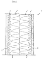
- the partition wall element shown in the figure - marked with 1- has two outer shells 2 and 3, which form the two outer surfaces of the partition wall element 1 and are usually made of plasterboard. Within this spaced-apart outer shells 2 and 3, a filling is introduced, which consists in the illustrated embodiment of two mirror-image arranged insulating panels 4 and 5.
- the multi-layer insulation boards 4 and 5 are made of mineral wool. The same multi-layer insulation boards are used.
- the multi-layer insulation boards 4 and 5 are arranged so that their layers of high density - denoted by 4 'and 5' - adjacent to the two outer shells 2 and 3.
- the two layers of low bulk density - labeled 4 "and 5" - border each other. All layers 4 ', 4 ", 5' and 5" are formed to have springing properties.
- the elasticity of the layers of low bulk density 4 "and 5" is distinguished from the layers of high bulk density 4 'and 5' by a comparatively high elasticity. It is set so that when installed with a certain excess, the layers of low density 4 "and 5" preferably compressed and built up in them restoring forces, the force and form closure of the high density layers 4 'and 5' with the outer shells 2 and 3 manufacture. This causes the desired vibration coupling of the outer shells 2 and 3 with the high density layers 4 'and 5'.
- the result of positive and positive connection construction with high mass results in very advantageous acoustic properties with good insulation properties of the partition wall element.
- the clear distance between the two outer shells 2 and 3 is 100 mm.
- the bulk density of the low bulk density layers 4 "and 5" is about 30 kg / m 3 , those of the high bulk density layers 4 'and 5' about 170 kg / m 3 .
- the clear distance between the two outer shells 2 and 3 may be 50 mm.
- For the bulk density can be in the layers of high density 4 'or 5' about 160 kg / m 3 , in the layers of low density 4 "or 5" about 30 kg / m 3 are selected.
Landscapes
- Engineering & Computer Science (AREA)
- Architecture (AREA)
- Structural Engineering (AREA)
- Physics & Mathematics (AREA)
- Electromagnetism (AREA)
- Civil Engineering (AREA)
- Building Environments (AREA)
- Water Treatment By Sorption (AREA)
- Bag Frames (AREA)
- Details Of Rigid Or Semi-Rigid Containers (AREA)
- Pharmaceuticals Containing Other Organic And Inorganic Compounds (AREA)
- Finishing Walls (AREA)
- Laminated Bodies (AREA)
Description
- Die Erfindung betrifft ein Trennwandelement gemäß dem Oberbegriff des Schutzanspruches 1.
- Derartige Trennwandelemente aus im Abstand zueinander angeordneten Außenschalen, insbesondere Gipskartonplatten, zwischen denen eine Füllung aus einem Wärmedämmstoff vorgesehen ist, sind in der Baupraxis bekannt Sie werden bevorzugt als Raumteiler eingesetzt. Im Vergleich zu massiven Konstruktionen liegen ihre Vorteile in der Leichtbauweise, der schnellen Montage und der daraus resultierenden Kostenvorteile. Ein Aufbau einesTrennwandelementes ist z.B. aus dem Gebrauchsmuster
DE 201 18 909 bekannt, bei welchem insbesondere eine Verbesserung der akustischen Eigenschaften im Vordergrund steht. Zu diesem Zweck wird bei dieser Konstruktion die Füllung in Sandwichbauweise aus mehreren Dämmstofflagen unterschiedlicher Spezifizierung hinsichtlich der Wärmedämm-. Schallschluck- und Elastizitätseigenschaften ausgeführt. Bei dem bekannten Trennwandelement nach dem Gebrauchsmuster ist ein dreilagiger Aufbau vorgesehen, der aus zwei außenliegenden Lagen hoher Rohdichte und einer innenliegenden Lage geringer Rohdichte besteht, wobei durch die Lage geringer Rohdichte eine kraft- und formschlüssige Schwingungskoppelung erzielt werden soll. - Der in dem Gebrauchsmuster
DE 201 18 909 beschriebene Aufbau eines Trennwandelements hat sich zwar hinsichtlich der Verbesserung der akustischen Eigenschaften durchaus bewährt, er weist aber durch den Aufbau aus mindestens drei Lagen miteinander nicht verbundener Dämmelemente praktische Nachteile in der Ausführung auf. So kann sich während des Einbaus die mittlere Lage mit geringer Rohdichte in einer oder beiden Lagen hoher Rohdichte verhaken, insbesondere im Bereich der Ständerprofile, wodurch es zu Störungen in der laminaren Schichtstruktur der Lagen infolge von Verwerfungen der mittleren Lage kommen kann. Diese Schichtstörungen können sich nachteilig auf die akustischen Eigenschaften auswirken und zu einer geringeren Schallabsorption als im ungestörten Aufbau führen. Um derartige Nachteile zu vermeiden, ist ein relativ hoher Arbeitsaufwand hinsichtlich eines sorgfältigen Arbeitens erforderlich, um die maximale Schallabsorption der ungestörten Schichtstruktur ausnutzen zu können. - Zur Erleichterung des Einbaus werden in dem bekannten Gebrauchsmuster bandartige Umreifungen der Sandwichelemente vorgeschlagen, bei denen aber das Lösen und gegebenenfalls Entfernen dieser Umreifungen im Einbauzustand nach Anbringen der zweiten Außenschale Schwierigkeiten bereiten kann. Eine weitere Lösung sieht die Verwendung vorgefertigter einstükkiger Produkte vor, die aber ihrerseits den Nachteil vorgegebener Außenabmessungen haben.
- Die Ausführung nach dem bekannten Gebrauchsmuster hat zudem einen erhöhten Logistikaufwand zur Folge, da unterschiedliche Dämmelemente mit unterschiedlichen Rohdichten für das Ausfüllen der Trennwand verwendet werden. Hinzu kommt, dass die oftmals fehlende optische Unterscheidbarkeit der Dämmelemente unterschiedlicher Rohdichte die Verwechslungsgefahr fördert, was zu einem falschen Schichtaufbau führen kann.
- Aus der
US 4,441,580 A1 ist ein Paneel bekannt, dass zur Geräuschdämmung als Raumteiler in Büros eingesetzt werden kann. Bei dieser leichten Trennwand handelt es sich um einen mehrschichtigen Paneelaufbau, bei dem immer ein niedrigdichtes Material innen und an seiner Außenseite ein luftundurchlässiges Material höherer Dichte sowie eine gelochte Platte aus mitteldichtem Material auf der anderen Seite angeordnet sind. Die Außenseiten müssen daher mit Stoff bespannt werden, um optisch ansprechend zu wirken. Dies macht den Aufbau kompliziert. Außerdem stellt sich das bereits aus anderen Wandaufbauten bekannte Problem, wonach zwischen zwei mehr oder weniger dichten Platten eine weiche aber große Dämmstoffplatte angeordnet werden muss, die leicht verrutscht. So kann auch hier während des Aufbaus die Dämmwolle leicht verhaken und den Aufbau verkomplizieren. - Aus
DE 24 49329 ist eine schalldämmende Trennwand nach dem Oberbegriff von Anspruch 1 bekannt. Sie ist in Verleimungs-Sandwich-Bauweise ausgeführt und hat einen Kern aus Bleiblech. Ein derartiger Aufbau hat es zum Ziel die Bleiplatte in der Mitte optimal zu entkoppeln, um die Koinzidenz-Grenzfrequenz der Trennwand herauf zu setzen. Andere technisch weniger aufwändige Prinzipien sind aus dem Stand der Technik nicht bekannt. - Aufgabe der Erfindung ist es, ein Trennwandelement derart auszulegen, dass die vorteilhaften akustischen Eigenschaften des Schichtaufbaus erhalten bleiben, und gleichzeitig die Bauausführung vereinfacht und kostengünstig ermöglicht wird.
- Diese Aufgabe wird erfindungsgemäß durch die im kennzeichnenden Teil des Anspruches 1 enthaltenen Merkmale gelöst, wobei zweckmäßige Weiterbildungen der Erfindung durch die in den Unteransprüchen angegebenen Merkmale gekennzeichnet sind.
- Nach Maßgabe der Erfindung ist die Füllung zwischen den Außenschalen, die zumeist aus Gipskartonplatten gebildet sind, aus mindestens zwei spiegelbildlich angeordneten mehrschichtigen Dämmplatten ausgebildet, deren Schichten eine unterschiedliche Spezifizierung hinsichtlich ihrer Wärmedämm-, Schallschluck- und/oder Elastizitätseigenschaften aufweisen. dabei zeichnen sich die mehrschichtigen Dämmplatten dadurch aus, dass sie einstückig sind und aus mindestens zwei aneinander grenzenden Schichten unterschiedlicher Rohdichte bestehen. Die Schichten geringer Rohdichte werden benachbart angeordnet, so dass die Schichten hoher Rohdichte unmittelbar an die Außenschalen grenzen, welche aus Gipskartonplatten aufgebaut sind. Diese Anordnung der Dämmplatten zeichnet sich dadurch aus, dass die Schichten hoher Rohdichte mit den beiden Außenschalen schwingungsgekoppelt sind. Die Schwingungskopplung resultiert aus einem Übermaß der Füllung gegenüber dem lichten Abstand der Außenschalen, welcher im Einbauzustand zum Aufbau von Rückstellkräften in den Schichten geringer Rohdichte führt, der einen Kraft- und Formschluß der äußeren Schichten hoher Rohdichte mit den Außenschalen bewirkt. Damit zeichnet sich das Trennwandelement durch hervorragende Schalldämmeigenschaften aus.
- Zweckmäßigerweise sind alle Schichten der mehrschichtigen Dämmplatten aus Mineralwolle ausgebildet.
- Vorzugsweise ist die Rohdichte in der Schicht geringer Rohdichte im Bereich von 25 bis 50 kg/m3, wodurch sich sehr hohe Elastizitätseigenschaften und der Aufbau entsprechender Rückstellkräfte nach dem Einbau zwischen den Außenschalen ergibt. Die an den Außenschalen angrenzenden Schichten hoher Rohdichte sind vorzugsweise mit einer Rohdichte zwischen 150 und 250 kg/m3 ausgeführt. Durch die erfindungsgemäße Ausbildung der Füllung werden die Außenschalen mit den direkt angrenzenden Lagen möglichst schwer und federnd zum Zweck der Schalldämmung ausgelegt. Die äußeren Schichten sollen dabei vorzugsweise auch noch Federungseigenschaften aufweisen, welche für das Mitschwingen und die Schallschluckeigenschaften von Vorteil sind.
- Die Verwendung von mehrschichtigen Dämmplatten reduziert den Montageaufwand für die Erstellung einer Trennwand. Probleme bei der Montage einer vorzugsweise dreilagigen Sandwich-Ausführung aus losen Dämmplatten, insbesondere der geordnete laminare Schichtaufbau werden durch die vorteilhafte Ausführung mit zwei spiegelbildlich angeordneten Dämmplatten erheblich verringert. Somit ist eine schnelle und kostengünstige Montage gewährleistet. Die Schichten hoher und geringer Rohdichte mehrschichtiger Dämmplatten lassen sich optisch einfach identifizieren, so dass eine Verwechslung und somit eine fehlerhafte Ausführung des Aufbaus ausgeschlossen ist. Weiterhin wird der Logistikaufwand erheblich reduziert, da bei der spiegelbildlichen Anordnung mit vorzugsweise gleichen mehrschichtigen Dämmplatten nur ein Produkt beschafft, zwischengelagert und verarbeitet werden muß. Damit gewährleistet die erfindungsgemäße Verwendung von mehrschichtigen Dämmplatten als Füllung einer Trennwand in besonders hohem Maße eine baulich einfache und kostengünstige Ausführung.
- Das erfindungsgemäße Trennwandelement kann auch als Verbundelement in verschiedenen Formen ausgebildet sein. So kann die Füllung aus den mehrschichtigen Dämmplatten auch als Halbzeug ausgebildet sein, wobei die beiden Dämmplatten in der geeigneten Anordnung fest miteinander verbunden sind, etwa durch Verkleben. Ebenfalls ist es möglich, das Trennwandelement als Fertigelement auszubilden, wobei die äußeren Dämmstoffschichten mit den beiden Außenschalen und auch die Dämmplatten untereinander fest verbunden, etwa verklebt sind.
- Nachfolgend wird ein bevorzugtes Ausführungsbeispiel der Erfindung anhand der einzigen Figur beschrieben, welche in schematischer Darstellung einen Querschnitt durch einen Teil eines Trennwandelements zeigt.
- Das in der Figur dargestellte Trennwandelement - bezeichnet mit 1- weist zwei Außenschalen 2 und 3 auf, welche die beiden Außenflächen des Trennwandelements 1 bilden und zumeist aus Gipskarton hergestellt sind. Innerhalb dieser mit Abstand zueinander angeordneten Außenschalen 2 und 3 ist eine Füllung eingebracht, die im dargestellten Ausführungsbeispiel aus zwei spiegelbildlich angeordneten Dämmplatten 4 und 5 besteht. Die mehrschichtigen Dämmplatten 4 und 5 sind aus Mineralwolle hergestellt. Es werden gleiche mehrschichtige Dämmplatten verwendet.
- Die mehrschichtigen Dämmplatten 4 und 5 werden so angeordnet, dass ihre Schichten hoher Rohdichte - bezeichnet mit 4' und 5'- an die beiden Außenschalen 2 und 3 angrenzen. Die beiden Schichten geringer Rohdichte - bezeichnet mit 4" und 5" - grenzen aneinander. Sämtliche Schichten 4', 4", 5' und 5" sind so ausgebildet, dass sie Federungseigenschaften aufweisen. Die Elastizität der Schichten geringer Rohdichte 4" und 5" zeichnet sich gegenüber den Schichten hoher Rohdichte 4' und 5' durch eine vergleichsweise hohe Elastizität auf. Sie ist so eingestellt, dass bei Einbau mit einem gewissen Übermaß die Schichten geringer Rohdichte 4" und 5" bevorzugt zusammengedrückt und in ihnen Rückstellkräfte aufgebaut werden, die einen Kraft- und Formschluß der Schichten hoher Rohdichte 4' und 5' mit den Außenschalen 2 und 3 herstellen. Dieser bewirkt die gewünschte Schwingungskopplung der Außenschalen 2 und 3 mit den Schichten hoher Rohdichte 4' und 5'. Der aus Kraft- und Formschluß resultierende Aufbau mit hoher Masse ergibt sehr vorteilhafte Akustikeigenschaften bei gleichzeitig guten Dämmeigenschaften des Trennwandelements.
- Im dargestellten Ausführungsbeispiel beträgt der lichte Abstand der beiden Außenschalen 2 und 3 100 mm. Als Füllung werden zwei spiegelbildlich angeordnete mehrschichtige Dämmplatten 4 und 5 mit jeweils einer Schicht hoher Rohdichte 4' bzw. 5' und einer Schicht geringer Rohdichte 4" bzw. 5" mit einer Gesamtdicke der Dämmplatte von jeweils 52 mm eingesetzt. Bezogen auf den lichten Abstand der Außenschalen 2 und 3 ergibt sich ein Einbauübermaß von 4 mm. Die Rohdichte der Schichten geringer Rohdichte 4" und 5" beträgt etwa 30 kg/m3, die der Schichten hoher Rohdichte 4' und 5' etwa 170 kg/m3. Nach dem Einbau resultieren Rückstellkräfte auf die außenliegenden Schichten hoher Rohdichte 4' und 5', die einen Form- und Kraftschluß mit den Außenschalen 2 und 3 und eine akustische Schwingungskopplung bewirken.
- In einer alternativen Ausführungsform kann der lichte Abstand zwischen den beiden Außenschalen 2 und 3 50 mm betragen. Die Gesamtdicke einer mehrschichtigen Dämmplatte 4, zu der eine zweite gleiche Dämmplatte 5 spiegelbildlich angeordnet ist, ist in diesem Fall 27 mm. Für die Rohdichte kann in den Schichten hoher Rohdichte 4' bzw. 5' etwa 160 kg/m3, in den Schichten geringer Rohdichte 4" bzw. 5" etwa 30 kg/m3 gewählt werden.
- Die Erfindung ist keinesfalls auf die beschriebenen beiden Ausführungsbeispiele und die genannten Werte eingeschränkt.
Claims (10)
- Trennwandelement für Raumteiler und dergleichen, gebildet aus mindestens zwei mit Abstand zueinander angeordneten Außenschalen und einer im Hohlraum zwischen den Außenschalen angeordneten Füllung mit Wärmedämmstoff Mineralwolle, wobei
die Füllung zwischen den Außenschalen (2; 3) aus mindestens zwei zueinander in Bezug auf die zwischen den Außenschalen verlaufende Symmetrieachse spiegelbildlich angeordneten mehrschichtigen Dämmplatten (4; 5) ausgebildet ist, wobei die Dämmplatten zwischen den Außenschalen angeordnet sind und deren Schichten (4', 4"; 5', 5") eine unterschiedliche Spezifizierung hinsichtlich ihrer Wärmedämm-, Schallschluck- und/oder Elastizitätseigenschaften aufweisen, wobei die Dämmplatten wenigstens zwei aneinandergrenzende Schichten unterschiedlicher Rohdichte aufweisen und so angeordnet sind, dass die Schichten mit geringer Rohdichte (4"; 5") innen benachbart sind und Schichten mit hoher Rohdichte (4'; 5') außen an die jeweilige Außenschale (2; 3) angrenzen und wobei jede mehrschichtige Dämmplatte (4; 5) einstückig ausgebildet ist
dadurch gekennzeichnet, dass
die Außenschalen als Gipskartonplatten ausgebildet sind und dass die mehrschichtigen Dämmplatten (4; 5) in Summe dicker sind als ein lichter Abstand zwischen den Gipskartonplatten, so dass durch elastische Verformung in den Schichten mit geringer Rohdichte eine Rückstellkraft aufgebaut wird, wobei die Füllung dichte- und/oder materialmäßig auf einen Strömungswiderstand von mindestens etwa 5 kPa•s/m2 eingestellt ist. - Trennwandelement nach Anspruch 1,
dadurch gekennzeichnet, dass
die zwei Schichten (4', 4"; 5', 5") unterschiedlicher Rohdichte eine solche mit einer hohen Rohdichte (4'; 5') zwischen 150 und 250 kg/m3 und eine solche mit einer geringen Rohdichte (4"; 5") zwischen 25 und 50 kg/m3 sind. - Trennwandelement nach einem der vorhergehenden Ansprüche,
dadurch gekennzeichnet, dass
die Füllung zwischen den zwei Außenschalen (2; 3) derart durch zwei der mehrschichtigen Dämmplatten (4; 5) gebildet ist, dass daran die jeweilige Schicht mit der hohen Rohdichte (4'; 5') an die Außenschalen (2; 3) angrenzt und die jeweiligen Schichten geringer Rohdichte (4"; 5") benachbart sind. - Trennwandelement nach Anspruch 3,
dadurch gekennzeichnet, dass
die an die Außenschalen (2; 3) angrenzenden Schichten mit der hohen Rohdichte (4'; 5') mit den Außenschalen (2; 3) schwingungsgekoppelt sind. - Trennwandelement nach Anspruch 4,
dadurch gekennzeichnet, dass
die Füllung ein Übermaß bezüglich des lichten Abstands zwischen den Außenschalen (2; 3) hat. - Trennwandelement nach Anspruch 5,
dadurch gekennzeichnet, dass
das Übermaß derart gewählt ist, dass im Einbauzustand die an die Außenschalen (2; 3) grenzenden Schichten hoher Rohdichte (4'; 5') durch Rückstellkräfte der Schichten geringer Rohdichte (4"; 5") an die Außenschalen (2; 3) gedrückt sind. - Trennwandelement nach einem der vorhergehenden Ansprüche,
dadurch gekennzeichnet, dass
die mehrschichtigen Dämmplatten bei einem Einsatz zwischen einem lichten Abstand der Außenschalen (2; 3) von 50 mm in den Schichten mit der hohen Rohdichte (4'; 5') eine solche von etwa 160 kg/m3 und in den Schichten mit geringer Rohdichte (4"; 5") eine solche von etwa 30 kg/m3, bei einem Einsatz zwischen einem lichten Abstand der Außenschalen (2;'3) von 100 mm in den Schichten mit der hohen Rohdichte (4'; 5') eine solche von etwa 170 kg/m3 und in den Schichten mit geringer Rohdichte (4"; 5") eine solche von etwa 30 kg/m3 aufweisen. - Trennwandelement nach einem der vorhergehenden Ansprüche,
dadurch gekennzeichnet, dass
die mehrschichtigen Dämmplatten (4; 5) aus Mineralwolle, insbesondere Steinwolle, bestehen. - Trennwandelement nach einem der vorhergehenden Ansprüche,
dadurch gekennzeichnet, dass
die Füllung als vorgefertigtes Halbzeug aus fest verbundenen mehrschichtigen Dämmplatten (4; 5) ausgebildet ist. - Trennwandelement nach einem der vorhergehenden Ansprüche,
dadurch gekennzeichnet, dass
dieses aus den Außenschalen (2; 3) und der Füllung aus den mehrschichtigen Dämmplatten (4; 5) als vorgefertigtes Produkt ausgebildet ist.
Applications Claiming Priority (3)
| Application Number | Priority Date | Filing Date | Title |
|---|---|---|---|
| DE20302119U | 2003-02-11 | ||
| DE20302119U DE20302119U1 (de) | 2003-02-11 | 2003-02-11 | Zweischalige Trennwand mit einer Füllung aus Mineralwolle |
| PCT/EP2004/001276 WO2004072397A1 (de) | 2003-02-11 | 2004-02-11 | Zweischalige trennwand mit einer füllung aus mineralwolle |
Publications (4)
| Publication Number | Publication Date |
|---|---|
| EP1597442A1 EP1597442A1 (de) | 2005-11-23 |
| EP1597442B1 EP1597442B1 (de) | 2010-04-07 |
| EP1597442B2 true EP1597442B2 (de) | 2016-11-02 |
| EP1597442B8 EP1597442B8 (de) | 2017-02-22 |
Family
ID=7979914
Family Applications (1)
| Application Number | Title | Priority Date | Filing Date |
|---|---|---|---|
| EP04709989.0A Expired - Lifetime EP1597442B8 (de) | 2003-02-11 | 2004-02-11 | Zweischalige trennwand mit einer füllung aus mineralwolle |
Country Status (8)
| Country | Link |
|---|---|
| EP (1) | EP1597442B8 (de) |
| AT (1) | ATE463627T1 (de) |
| DE (2) | DE20302119U1 (de) |
| DK (1) | DK1597442T4 (de) |
| NO (1) | NO339519B1 (de) |
| PL (1) | PL217392B1 (de) |
| RU (1) | RU2339770C2 (de) |
| WO (1) | WO2004072397A1 (de) |
Families Citing this family (8)
| Publication number | Priority date | Publication date | Assignee | Title |
|---|---|---|---|---|
| DE10339829A1 (de) * | 2003-08-29 | 2005-03-31 | Deutsche Rockwool Mineralwoll Gmbh + Co Ohg | Gebäudewand und Dämmschicht sowie Dämmelement zum Einbau in eine Gebäudewand |
| US7732043B2 (en) * | 2005-09-15 | 2010-06-08 | Usg Interiors, Inc. | Ceiling tile with non uniform binder composition |
| US9194124B2 (en) | 2011-12-09 | 2015-11-24 | 3M Innovative Properties Company | Acoustic light panel |
| CN104309184B (zh) * | 2014-10-13 | 2016-04-20 | 山东理工大学 | 赤泥结合膨胀蛭石多面彩饰轻质墙体材料的制备方法 |
| CN104309185B (zh) * | 2014-10-13 | 2016-08-17 | 山东理工大学 | 赤泥-膨胀珍珠岩多面彩饰轻质墙体材料的制备方法 |
| CN104309228B (zh) * | 2014-10-13 | 2015-12-02 | 山东理工大学 | 一种多面彩色装饰轻质墙体材料的制备方法 |
| RU2678293C1 (ru) * | 2018-02-19 | 2019-01-24 | Ооо Фирма "Вефт" | Монолитная звукоизоляционная стеновая конструкция |
| CN109024997B (zh) * | 2018-07-31 | 2021-05-04 | 南阳理工学院 | 一种播音室用隔音墙 |
Citations (2)
| Publication number | Priority date | Publication date | Assignee | Title |
|---|---|---|---|---|
| DE10147831A1 (de) † | 2001-02-21 | 2002-09-19 | Rockwool Mineralwolle | Gebäudewand, Dämmstoffelement für eine Gebäudewand und Befestigungselement für ein Dämmstoffelement |
| WO2004009927A1 (de) † | 2002-07-19 | 2004-01-29 | Deutsche Rockwool Mineralwool Gmbh & Co. Ohg | Dämmschicht aus mineralfasern und gebäudewand |
Family Cites Families (12)
| Publication number | Priority date | Publication date | Assignee | Title |
|---|---|---|---|---|
| BE791905A (fr) * | 1971-11-25 | 1973-05-24 | Saint Gobain | Element de construction destine a realiser une isolation acoustique |
| GB1458637A (en) * | 1973-10-18 | 1976-12-15 | Anti Sound Ab | Partition |
| DE2611033C2 (de) * | 1976-03-16 | 1982-04-01 | Armstrong Cork Co., 17604 Lancaster, Pa. | Feuerbeständige leichte Trennwand für Räume von Gebäuden |
| US4441580A (en) * | 1980-10-17 | 1984-04-10 | Steelcase Inc. | Acoustical control media |
| DE3202078A1 (de) | 1982-01-23 | 1983-08-04 | IT - Isoliertechnik und Schallschutz GmbH, 4830 Gütersloh | Schalldaempfer-kulisse |
| DE3244585A1 (de) | 1982-11-15 | 1984-05-17 | Bernd 4902 Bad Salzuflen Friemuth | Kunstschaumisolierelement |
| DE4030407A1 (de) * | 1990-09-26 | 1992-04-02 | Pape Hans | Schalldaemmende wand |
| DE4137241C2 (de) | 1991-11-13 | 1996-05-30 | Eckhard A Ullrich | Als "Sandwichelement" ausgebildetes, dünnwandiges Schall- und Feuerschutzelement |
| RU2097503C1 (ru) * | 1995-10-23 | 1997-11-27 | Товарищество с ограниченной ответственностью Инженерная фирма "АПА-проект" | Многослойная панель |
| MY138537A (en) * | 1999-05-27 | 2009-06-30 | Rockwool Int | Mineral fibre insulating board comprising a rigid surface layer and process for the preparation thereof |
| WO2002042576A1 (en) | 2000-11-24 | 2002-05-30 | Rockwool International A/S | A sound reducing board and a process for the manufacture of the board |
| DE20118909U1 (de) | 2001-11-20 | 2003-03-27 | Saint-Gobain Isover G+H AG, 68526 Ladenburg | Trennwandelement für Raumteiler u.dgl. mit einer Füllung mit Wärmedämmstoff, insbesondere Mineralwolle |
-
2003
- 2003-02-11 DE DE20302119U patent/DE20302119U1/de not_active Expired - Lifetime
-
2004
- 2004-02-11 DE DE502004010997T patent/DE502004010997D1/de not_active Expired - Lifetime
- 2004-02-11 WO PCT/EP2004/001276 patent/WO2004072397A1/de not_active Ceased
- 2004-02-11 DK DK04709989.0T patent/DK1597442T4/en active
- 2004-02-11 RU RU2005127455/03A patent/RU2339770C2/ru active
- 2004-02-11 AT AT04709989T patent/ATE463627T1/de active
- 2004-02-11 EP EP04709989.0A patent/EP1597442B8/de not_active Expired - Lifetime
- 2004-02-11 PL PL377580A patent/PL217392B1/pl unknown
-
2005
- 2005-09-09 NO NO20054190A patent/NO339519B1/no not_active IP Right Cessation
Patent Citations (2)
| Publication number | Priority date | Publication date | Assignee | Title |
|---|---|---|---|---|
| DE10147831A1 (de) † | 2001-02-21 | 2002-09-19 | Rockwool Mineralwolle | Gebäudewand, Dämmstoffelement für eine Gebäudewand und Befestigungselement für ein Dämmstoffelement |
| WO2004009927A1 (de) † | 2002-07-19 | 2004-01-29 | Deutsche Rockwool Mineralwool Gmbh & Co. Ohg | Dämmschicht aus mineralfasern und gebäudewand |
Also Published As
| Publication number | Publication date |
|---|---|
| RU2005127455A (ru) | 2007-03-20 |
| DK1597442T4 (en) | 2017-01-30 |
| DE502004010997D1 (de) | 2010-05-20 |
| ATE463627T1 (de) | 2010-04-15 |
| PL377580A1 (pl) | 2006-02-06 |
| EP1597442B8 (de) | 2017-02-22 |
| EP1597442A1 (de) | 2005-11-23 |
| NO339519B1 (no) | 2016-12-27 |
| DK1597442T3 (da) | 2010-08-09 |
| RU2339770C2 (ru) | 2008-11-27 |
| DE20302119U1 (de) | 2003-07-03 |
| PL217392B1 (pl) | 2014-07-31 |
| WO2004072397A1 (de) | 2004-08-26 |
| NO20054190L (no) | 2005-09-09 |
| EP1597442B1 (de) | 2010-04-07 |
Similar Documents
| Publication | Publication Date | Title |
|---|---|---|
| EP0701647B1 (de) | Bauelement | |
| DE69936046T2 (de) | Sandwich-Schallisolierungselement | |
| DE202007017699U1 (de) | Trennwandelement | |
| DE202009001532U1 (de) | Dämmsystem | |
| DE2736164A1 (de) | Vorgefertigtes schallisolations- und schallabsorptionselement zur wandverkleidung von raeumen | |
| EP1597442B2 (de) | Zweischalige trennwand mit einer f llung aus mineralwolle | |
| WO2016091244A2 (de) | Paneelsystem für die erstellung von räumen | |
| EP2006462B1 (de) | Akustik-Mehrschichtplatte | |
| DE102007024356A1 (de) | Sandwich-Platte und deren Verwendung | |
| DE60218060T2 (de) | Trennwandelement für trennwände und dergleichen mit einer füllung aus wärmeisolierendem material, insbesondere mineralwolle | |
| DE4433161A1 (de) | Hinterlüftete Dämmplatte | |
| DE202007018806U1 (de) | Dämmplatte | |
| DE10122265B4 (de) | Holzbautafel | |
| CH683855A5 (de) | Schallabsorptionsplatte. | |
| DE102007062068A1 (de) | Innendämmsystem für Gebäude | |
| DE10219981B4 (de) | Holzbautafel | |
| DE19640402A1 (de) | Schalldämmendes Verbundelement | |
| AT292979B (de) | Plattenförmiges, schalldämmendes, zweischalig aufgebautes Bauelement mit Schüttgutfüllung | |
| DE102014105503A1 (de) | Wand- oder Deckensystem für Gebäude | |
| CH494870A (de) | Plattenförmiges, schalldämmendes, zweischalig aufgebautes Bauelement mit Schüttgutfüllung | |
| EP1500753B1 (de) | In Trockenbauweise erstellte Trennwand und Verwendung einer Gipskartonplatte | |
| EP2034100A2 (de) | Gips-Lochplatte und Verfahren zur Herstellung einer abgehängten Decke | |
| DE202012012559U1 (de) | Dämmplattenanordnung, insbesondere Stufen-Dämmplatte, Trockenestrich und Dämmvorrichtung | |
| DE10055481A1 (de) | Selbsttragende Platte und Wandelement aus nachwachsenden Rohstoffen | |
| DE102010012202A1 (de) | Trennwandelement, insbesondere für eine mobile Trennwand, sowie entsprechende Trennwand |
Legal Events
| Date | Code | Title | Description |
|---|---|---|---|
| PUAI | Public reference made under article 153(3) epc to a published international application that has entered the european phase |
Free format text: ORIGINAL CODE: 0009012 |
|
| 17P | Request for examination filed |
Effective date: 20050906 |
|
| AK | Designated contracting states |
Kind code of ref document: A1 Designated state(s): AT BE BG CH CY CZ DE DK EE ES FI FR GB GR HU IE IT LI LU MC NL PT RO SE SI SK TR |
|
| AX | Request for extension of the european patent |
Extension state: AL LT LV MK |
|
| 17Q | First examination report despatched |
Effective date: 20061207 |
|
| GRAP | Despatch of communication of intention to grant a patent |
Free format text: ORIGINAL CODE: EPIDOSNIGR1 |
|
| GRAS | Grant fee paid |
Free format text: ORIGINAL CODE: EPIDOSNIGR3 |
|
| GRAA | (expected) grant |
Free format text: ORIGINAL CODE: 0009210 |
|
| AK | Designated contracting states |
Kind code of ref document: B1 Designated state(s): AT BE BG CH CY CZ DE DK EE ES FI FR GB GR HU IE IT LI LU MC NL PT RO SE SI SK TR |
|
| AX | Request for extension of the european patent |
Extension state: AL LT LV MK |
|
| REG | Reference to a national code |
Ref country code: GB Ref legal event code: FG4D Free format text: NOT ENGLISH |
|
| REG | Reference to a national code |
Ref country code: CH Ref legal event code: EP |
|
| REG | Reference to a national code |
Ref country code: IE Ref legal event code: FG4D Free format text: LANGUAGE OF EP DOCUMENT: GERMAN |
|
| REF | Corresponds to: |
Ref document number: 502004010997 Country of ref document: DE Date of ref document: 20100520 Kind code of ref document: P |
|
| REG | Reference to a national code |
Ref country code: NL Ref legal event code: T3 |
|
| REG | Reference to a national code |
Ref country code: SE Ref legal event code: TRGR |
|
| REG | Reference to a national code |
Ref country code: DK Ref legal event code: T3 |
|
| PG25 | Lapsed in a contracting state [announced via postgrant information from national office to epo] |
Ref country code: SI Free format text: LAPSE BECAUSE OF FAILURE TO SUBMIT A TRANSLATION OF THE DESCRIPTION OR TO PAY THE FEE WITHIN THE PRESCRIBED TIME-LIMIT Effective date: 20100407 |
|
| LTIE | Lt: invalidation of european patent or patent extension |
Effective date: 20100407 |
|
| REG | Reference to a national code |
Ref country code: IE Ref legal event code: FD4D |
|
| PG25 | Lapsed in a contracting state [announced via postgrant information from national office to epo] |
Ref country code: ES Free format text: LAPSE BECAUSE OF FAILURE TO SUBMIT A TRANSLATION OF THE DESCRIPTION OR TO PAY THE FEE WITHIN THE PRESCRIBED TIME-LIMIT Effective date: 20100718 |
|
| PG25 | Lapsed in a contracting state [announced via postgrant information from national office to epo] |
Ref country code: FI Free format text: LAPSE BECAUSE OF FAILURE TO SUBMIT A TRANSLATION OF THE DESCRIPTION OR TO PAY THE FEE WITHIN THE PRESCRIBED TIME-LIMIT Effective date: 20100407 |
|
| PG25 | Lapsed in a contracting state [announced via postgrant information from national office to epo] |
Ref country code: CY Free format text: LAPSE BECAUSE OF FAILURE TO SUBMIT A TRANSLATION OF THE DESCRIPTION OR TO PAY THE FEE WITHIN THE PRESCRIBED TIME-LIMIT Effective date: 20100421 Ref country code: GR Free format text: LAPSE BECAUSE OF FAILURE TO SUBMIT A TRANSLATION OF THE DESCRIPTION OR TO PAY THE FEE WITHIN THE PRESCRIBED TIME-LIMIT Effective date: 20100708 |
|
| PLBI | Opposition filed |
Free format text: ORIGINAL CODE: 0009260 |
|
| PG25 | Lapsed in a contracting state [announced via postgrant information from national office to epo] |
Ref country code: PT Free format text: LAPSE BECAUSE OF FAILURE TO SUBMIT A TRANSLATION OF THE DESCRIPTION OR TO PAY THE FEE WITHIN THE PRESCRIBED TIME-LIMIT Effective date: 20100809 Ref country code: IE Free format text: LAPSE BECAUSE OF FAILURE TO SUBMIT A TRANSLATION OF THE DESCRIPTION OR TO PAY THE FEE WITHIN THE PRESCRIBED TIME-LIMIT Effective date: 20100407 Ref country code: EE Free format text: LAPSE BECAUSE OF FAILURE TO SUBMIT A TRANSLATION OF THE DESCRIPTION OR TO PAY THE FEE WITHIN THE PRESCRIBED TIME-LIMIT Effective date: 20100407 |
|
| 26 | Opposition filed |
Opponent name: ROCKWOOL INTERNATIONAL A/S Effective date: 20110107 |
|
| PLAX | Notice of opposition and request to file observation + time limit sent |
Free format text: ORIGINAL CODE: EPIDOSNOBS2 |
|
| PG25 | Lapsed in a contracting state [announced via postgrant information from national office to epo] |
Ref country code: RO Free format text: LAPSE BECAUSE OF FAILURE TO SUBMIT A TRANSLATION OF THE DESCRIPTION OR TO PAY THE FEE WITHIN THE PRESCRIBED TIME-LIMIT Effective date: 20100407 Ref country code: CZ Free format text: LAPSE BECAUSE OF FAILURE TO SUBMIT A TRANSLATION OF THE DESCRIPTION OR TO PAY THE FEE WITHIN THE PRESCRIBED TIME-LIMIT Effective date: 20100407 Ref country code: SK Free format text: LAPSE BECAUSE OF FAILURE TO SUBMIT A TRANSLATION OF THE DESCRIPTION OR TO PAY THE FEE WITHIN THE PRESCRIBED TIME-LIMIT Effective date: 20100407 |
|
| PG25 | Lapsed in a contracting state [announced via postgrant information from national office to epo] |
Ref country code: IT Free format text: LAPSE BECAUSE OF FAILURE TO SUBMIT A TRANSLATION OF THE DESCRIPTION OR TO PAY THE FEE WITHIN THE PRESCRIBED TIME-LIMIT Effective date: 20100407 |
|
| PLBB | Reply of patent proprietor to notice(s) of opposition received |
Free format text: ORIGINAL CODE: EPIDOSNOBS3 |
|
| BERE | Be: lapsed |
Owner name: SAINT-GOBAIN ISOVER Effective date: 20110228 |
|
| PG25 | Lapsed in a contracting state [announced via postgrant information from national office to epo] |
Ref country code: MC Free format text: LAPSE BECAUSE OF NON-PAYMENT OF DUE FEES Effective date: 20110228 |
|
| REG | Reference to a national code |
Ref country code: CH Ref legal event code: PL |
|
| PG25 | Lapsed in a contracting state [announced via postgrant information from national office to epo] |
Ref country code: CH Free format text: LAPSE BECAUSE OF NON-PAYMENT OF DUE FEES Effective date: 20110228 Ref country code: LI Free format text: LAPSE BECAUSE OF NON-PAYMENT OF DUE FEES Effective date: 20110228 |
|
| PG25 | Lapsed in a contracting state [announced via postgrant information from national office to epo] |
Ref country code: BE Free format text: LAPSE BECAUSE OF NON-PAYMENT OF DUE FEES Effective date: 20110228 |
|
| PLCK | Communication despatched that opposition was rejected |
Free format text: ORIGINAL CODE: EPIDOSNREJ1 |
|
| REG | Reference to a national code |
Ref country code: AT Ref legal event code: MM01 Ref document number: 463627 Country of ref document: AT Kind code of ref document: T Effective date: 20110211 |
|
| APBM | Appeal reference recorded |
Free format text: ORIGINAL CODE: EPIDOSNREFNO |
|
| APBP | Date of receipt of notice of appeal recorded |
Free format text: ORIGINAL CODE: EPIDOSNNOA2O |
|
| APAH | Appeal reference modified |
Free format text: ORIGINAL CODE: EPIDOSCREFNO |
|
| PG25 | Lapsed in a contracting state [announced via postgrant information from national office to epo] |
Ref country code: AT Free format text: LAPSE BECAUSE OF NON-PAYMENT OF DUE FEES Effective date: 20110211 |
|
| APBQ | Date of receipt of statement of grounds of appeal recorded |
Free format text: ORIGINAL CODE: EPIDOSNNOA3O |
|
| PG25 | Lapsed in a contracting state [announced via postgrant information from national office to epo] |
Ref country code: LU Free format text: LAPSE BECAUSE OF NON-PAYMENT OF DUE FEES Effective date: 20110211 |
|
| PG25 | Lapsed in a contracting state [announced via postgrant information from national office to epo] |
Ref country code: TR Free format text: LAPSE BECAUSE OF FAILURE TO SUBMIT A TRANSLATION OF THE DESCRIPTION OR TO PAY THE FEE WITHIN THE PRESCRIBED TIME-LIMIT Effective date: 20100407 Ref country code: BG Free format text: LAPSE BECAUSE OF FAILURE TO SUBMIT A TRANSLATION OF THE DESCRIPTION OR TO PAY THE FEE WITHIN THE PRESCRIBED TIME-LIMIT Effective date: 20100707 |
|
| PG25 | Lapsed in a contracting state [announced via postgrant information from national office to epo] |
Ref country code: HU Free format text: LAPSE BECAUSE OF FAILURE TO SUBMIT A TRANSLATION OF THE DESCRIPTION OR TO PAY THE FEE WITHIN THE PRESCRIBED TIME-LIMIT Effective date: 20100407 |
|
| REG | Reference to a national code |
Ref country code: FR Ref legal event code: PLFP Year of fee payment: 12 |
|
| APBU | Appeal procedure closed |
Free format text: ORIGINAL CODE: EPIDOSNNOA9O |
|
| PLAY | Examination report in opposition despatched + time limit |
Free format text: ORIGINAL CODE: EPIDOSNORE2 |
|
| PLBC | Reply to examination report in opposition received |
Free format text: ORIGINAL CODE: EPIDOSNORE3 |
|
| REG | Reference to a national code |
Ref country code: FR Ref legal event code: PLFP Year of fee payment: 13 |
|
| PUAH | Patent maintained in amended form |
Free format text: ORIGINAL CODE: 0009272 |
|
| STAA | Information on the status of an ep patent application or granted ep patent |
Free format text: STATUS: PATENT MAINTAINED AS AMENDED |
|
| 27A | Patent maintained in amended form |
Effective date: 20161102 |
|
| AK | Designated contracting states |
Kind code of ref document: B2 Designated state(s): AT BE BG CH CY CZ DE DK EE ES FI FR GB GR HU IE IT LI LU MC NL PT RO SE SI SK TR |
|
| AX | Request for extension of the european patent |
Extension state: AL LT LV MK |
|
| REG | Reference to a national code |
Ref country code: DE Ref legal event code: R102 Ref document number: 502004010997 Country of ref document: DE |
|
| GRAT | Correction requested after decision to grant or after decision to maintain patent in amended form |
Free format text: ORIGINAL CODE: EPIDOSNCDEC |
|
| REG | Reference to a national code |
Ref country code: FR Ref legal event code: PLFP Year of fee payment: 14 |
|
| REG | Reference to a national code |
Ref country code: DK Ref legal event code: T4 Effective date: 20170127 |
|
| REG | Reference to a national code |
Ref country code: NL Ref legal event code: FP |
|
| REG | Reference to a national code |
Ref country code: SE Ref legal event code: RPEO |
|
| REG | Reference to a national code |
Ref country code: FR Ref legal event code: PLFP Year of fee payment: 15 |
|
| PGFP | Annual fee paid to national office [announced via postgrant information from national office to epo] |
Ref country code: GB Payment date: 20211230 Year of fee payment: 19 Ref country code: SE Payment date: 20211229 Year of fee payment: 19 |
|
| PGFP | Annual fee paid to national office [announced via postgrant information from national office to epo] |
Ref country code: DK Payment date: 20220209 Year of fee payment: 19 Ref country code: DE Payment date: 20211230 Year of fee payment: 19 |
|
| PGFP | Annual fee paid to national office [announced via postgrant information from national office to epo] |
Ref country code: NL Payment date: 20220118 Year of fee payment: 19 Ref country code: FR Payment date: 20220118 Year of fee payment: 19 |
|
| REG | Reference to a national code |
Ref country code: DE Ref legal event code: R119 Ref document number: 502004010997 Country of ref document: DE |
|
| REG | Reference to a national code |
Ref country code: DK Ref legal event code: EBP Effective date: 20230228 |
|
| REG | Reference to a national code |
Ref country code: SE Ref legal event code: EUG |
|
| REG | Reference to a national code |
Ref country code: NL Ref legal event code: MM Effective date: 20230301 |
|
| GBPC | Gb: european patent ceased through non-payment of renewal fee |
Effective date: 20230211 |
|
| PG25 | Lapsed in a contracting state [announced via postgrant information from national office to epo] |
Ref country code: SE Free format text: LAPSE BECAUSE OF NON-PAYMENT OF DUE FEES Effective date: 20230212 |
|
| PG25 | Lapsed in a contracting state [announced via postgrant information from national office to epo] |
Ref country code: NL Free format text: LAPSE BECAUSE OF NON-PAYMENT OF DUE FEES Effective date: 20230301 |
|
| PG25 | Lapsed in a contracting state [announced via postgrant information from national office to epo] |
Ref country code: GB Free format text: LAPSE BECAUSE OF NON-PAYMENT OF DUE FEES Effective date: 20230211 |
|
| PG25 | Lapsed in a contracting state [announced via postgrant information from national office to epo] |
Ref country code: GB Free format text: LAPSE BECAUSE OF NON-PAYMENT OF DUE FEES Effective date: 20230211 Ref country code: FR Free format text: LAPSE BECAUSE OF NON-PAYMENT OF DUE FEES Effective date: 20230228 Ref country code: DK Free format text: LAPSE BECAUSE OF NON-PAYMENT OF DUE FEES Effective date: 20230228 Ref country code: DE Free format text: LAPSE BECAUSE OF NON-PAYMENT OF DUE FEES Effective date: 20230901 |