EP1596099A1 - Gewindespindel-Mutter zur Vermeidung von Spiel und Vorrichtung mit derselben - Google Patents
Gewindespindel-Mutter zur Vermeidung von Spiel und Vorrichtung mit derselben Download PDFInfo
- Publication number
- EP1596099A1 EP1596099A1 EP05252936A EP05252936A EP1596099A1 EP 1596099 A1 EP1596099 A1 EP 1596099A1 EP 05252936 A EP05252936 A EP 05252936A EP 05252936 A EP05252936 A EP 05252936A EP 1596099 A1 EP1596099 A1 EP 1596099A1
- Authority
- EP
- European Patent Office
- Prior art keywords
- nut
- leadscrew
- moving body
- nuts
- biasing
- Prior art date
- Legal status (The legal status is an assumption and is not a legal conclusion. Google has not performed a legal analysis and makes no representation as to the accuracy of the status listed.)
- Withdrawn
Links
Images


Classifications
-
- F—MECHANICAL ENGINEERING; LIGHTING; HEATING; WEAPONS; BLASTING
- F16—ENGINEERING ELEMENTS AND UNITS; GENERAL MEASURES FOR PRODUCING AND MAINTAINING EFFECTIVE FUNCTIONING OF MACHINES OR INSTALLATIONS; THERMAL INSULATION IN GENERAL
- F16H—GEARING
- F16H25/00—Gearings comprising primarily only cams, cam-followers and screw-and-nut mechanisms
- F16H25/18—Gearings comprising primarily only cams, cam-followers and screw-and-nut mechanisms for conveying or interconverting oscillating or reciprocating motions
- F16H25/20—Screw mechanisms
- F16H25/2003—Screw mechanisms with arrangements for taking up backlash
- F16H25/2006—Screw mechanisms with arrangements for taking up backlash with more than one nut or with nuts consisting of more than one bearing part
-
- F—MECHANICAL ENGINEERING; LIGHTING; HEATING; WEAPONS; BLASTING
- F16—ENGINEERING ELEMENTS AND UNITS; GENERAL MEASURES FOR PRODUCING AND MAINTAINING EFFECTIVE FUNCTIONING OF MACHINES OR INSTALLATIONS; THERMAL INSULATION IN GENERAL
- F16H—GEARING
- F16H25/00—Gearings comprising primarily only cams, cam-followers and screw-and-nut mechanisms
- F16H25/18—Gearings comprising primarily only cams, cam-followers and screw-and-nut mechanisms for conveying or interconverting oscillating or reciprocating motions
- F16H25/20—Screw mechanisms
-
- Y—GENERAL TAGGING OF NEW TECHNOLOGICAL DEVELOPMENTS; GENERAL TAGGING OF CROSS-SECTIONAL TECHNOLOGIES SPANNING OVER SEVERAL SECTIONS OF THE IPC; TECHNICAL SUBJECTS COVERED BY FORMER USPC CROSS-REFERENCE ART COLLECTIONS [XRACs] AND DIGESTS
- Y10—TECHNICAL SUBJECTS COVERED BY FORMER USPC
- Y10T—TECHNICAL SUBJECTS COVERED BY FORMER US CLASSIFICATION
- Y10T74/00—Machine element or mechanism
- Y10T74/18—Mechanical movements
- Y10T74/18568—Reciprocating or oscillating to or from alternating rotary
- Y10T74/18576—Reciprocating or oscillating to or from alternating rotary including screw and nut
- Y10T74/18728—Backlash
Definitions
- the present invention relates to a moving body, which is screwable to and movable on a leadscrew, and an actuating device having the moving body.
- spherical bodies whose diameters are larger than clearances between nuts and the leadscrew, are provided between the nuts and the leadscrew so as to press the nuts onto the leadscrew. Further, pitches of the nuts are made different from that of the leadscrew so as to press the nuts onto the leadscrew.
- These methods are capable of restraining to form the clearances between the nuts and the leadscrew.
- frictional resistances between the nuts and the leadscrew must be further greater, so that a high power driving unit is required.
- the leadscrew the nuts and the spherical bodies are abraded, the clearances are easily formed, so that maintenance cost must be increased.
- the present invention has been invented to address the problems of the conventional actuating devices.
- An object of the present invention is to provide a low cost moving body of an actuating device, in which clearances between nuts and a leadscrew can be automatically and rapidly eliminate with a simple structure.
- the present invention has following structures.
- a distance between contact faces of the first nut and second nut, which contact the wedge member may be gradually reduced in the biasing direction of the biasing member, and the distance between the first nut and second nut may be increased by moving the wedge member, which contact the contact faces, in the biasing direction.
- the wedge member when the force pressing the nuts onto the leadscrew is reduced and clearances are formed between the nuts and the leadscrew, the wedge member is moved by the elasticity of the biasing member so as to increase and maintain the distance between the nuts, so that the pressing force can be maintained and the clearances can be eliminated Unlike the conventional moving body having the turnable spacer, the moving body has a simple structure, its manufacturing cost can be reduced, and the distance between the nuts can be rapidly and smoothly increased without frictional resistance.
- the moving body may further comprise a holding member being provided to at least one of the nuts, and the biasing member may be elastically held between the wedge member and the holding member.
- the holding member may be a cylindrical member covering outer circumferential faces of the first and second nuts.
- one end of the biasing member may be fitted in a concave section of the wedge member.
- the biasing member can be provided in a small space.
- the first nut may have a first engage section
- the second nut may have a second engage section, which is engaged with the first engage section.
- the clearances can be automatically eliminated, so that play or jolt of the moving body can be prevented.
- the clearances can be rapidly and smoothly eliminated.
- the structure of the moving body can be simple and compact. Further, manufacturing costs of the moving body and the actuating device can be reduced.
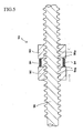
- FIG. 1 A leadscrew type actuating device of the present embodiment is shown in Figs. 1-3.
- Longitudinal sectional views of the actuating device A are shown in Figs. 1 and 2.
- Fig. 3 is the sectional view taken along a line X-X shown in Fig. 1;
- Fig. 1 is the sectional view taken along a line Y-Y shown in Fig. 3.
- a male screw section is formed on an outer circumferential face of a lead screw 2, which is rotated by a driving unit (not shown).
- a moving body 4 is linearly reciprocally moved along the leadscrew 2.
- the moving body 4 includes a first nut 6 and a second nut 8, which are screwed with the male screw section of the leadscrew 2 and engaged each other. With this structure, the moving body 4 is moved on the leadscrew 2 by rotating the leadscrew 2.
- Fig. 4A is a perspective view of the first nut 6, and Fig. 4B is a perspective view of the second nut 8.
- female screw sections (not shown), which are capable of screwing with the male screw section of the leadscrew 2, are respectively formed on inner circumferential faces of the first and second nuts 6 and 8.
- a member to be moved (not shown), e.g., tool, can be attached to the attachment nut 10.
- the member can be linearly moved along the leadscrew 2 together with the moving body 4.
- the projections 14 of the second nut 8 are respectively fitted in the concave parts 12 of the first nut 6.
- the first and second nuts 6 and 8 are mutually engaged.
- the nuts 6 and 8 are prohibited to rotate in the circumferential direction of the leadscrew 2, but allowed to move in the axial direction thereof. Further, they are capable of moving close and away each other.
- wedge members 18 are respectively provided in the grooves 16.
- a side face of the wedge member 18, which faces the inner bottom face 16a of the groove 16, is a slope face corresponding to the inner bottom face 16a.
- a concave section 18a is formed in an outer end face of each wedge member 18, which faces an inner circumferential face of the cylindrical member 20.
- a spring 22 is elastically provided between an inner bottom face of each concave section 18a and the inner circumferential face of the cylindrical member 20. With this structure, the wedge members 18 are always biased toward the leadscrew 2 by the springs 22.
- the distance between the side face 7 of the first nut 6 and the inner bottom face 16a of each groove 16 of the second nut 8 is gradually reduced toward the leadscrew 2. Therefore, the elasticity of the springs 22 bias the wedge members 18 to increase said distances. The elasticity of the springs 22 press the first and second nuts 6 and 8 onto the leadscrew 2 as pressing forces.
- the first and second nuts 6 and 8 are always biased to move away each other by the springs 22 and the wedge members 18, so that the first and second nuts 6 and 8 are pressed onto the leadscrew 2.
- a clamping force of the nuts 6 and 8, which clamps the wedge members 18, is reduced.
- the wedge members 18 are moved in the biasing directions of the springs 22, so that the distance between the nuts 6 and 8 are increased by the wedge members 18 and the clearances are automatically eliminated (see Fig. 2).
- the springs 22 are provided to move only the wedge members 18 in the biasing directions when clearances are formed between the wedge members 18 and the nuts 6 and 8. Therefore, the springs 22 need no great elasticity. Therefore, clearances between the leadscrew 2 and the nuts 6 and 8 can be eliminated without increasing the pressing forces, and required torque for rotating the leadscrew 2 can be reduced.
- first and second nuts 6 and 8 are move away each other by merely moving the wedge members 18 in the biasing directions, dynamic resistance of moving the nuts 6 and 8 is much smaller than that of the conventional actuating device, in which the distance between the nuts are increased by turning the screw spacer. Therefore, even if the pressing forces are reduced or clearances are formed between the leadscrew 2 and the nuts 6 and 8, the distance between the nuts 6 and 8 can be rapidly and smoothly increased so that the pressing forces can be maintained and the clearances can be automatically eliminated.
- the inner bottom faces 16a of the grooves 16 are slope faces, and the distance between the first and second nuts 6 and 8 is increased by moving the wedge members 18 in the biasing directions of the springs 22.
- Means for increasing the distance between the nuts 6 and 8 is not limited to the embodiment.
- the distance between the nuts 6 and 8 can be increased by taper-shaped wedge members 18, whose widths are gradually reduced toward the leadscrew 2.
- outer ends of the taper-shaped wedge members 18 are slightly projected outward from the outer circumferential faces of the nuts 6 and 8. The taper-shaped wedge members 18 are moved toward the leadscrew 2 by biasing members so as to increase the distance between the nuts 6 and 8.
- means for holding the biasing members e.g., springs 22, is not limited to the cylindrical member 20.
- the holding member may be extended sections, which are extended from the outer circumferential face of the first nut 6 toward the outer circumferential face of the second nut 8.
- the moving body 4 of the present invention can be applied to many leadscrew type actuating devices.
Landscapes
- Engineering & Computer Science (AREA)
- General Engineering & Computer Science (AREA)
- Mechanical Engineering (AREA)
- Transmission Devices (AREA)
Applications Claiming Priority (2)
| Application Number | Priority Date | Filing Date | Title |
|---|---|---|---|
| JP2004145397 | 2004-05-14 | ||
| JP2004145397A JP2005325944A (ja) | 2004-05-14 | 2004-05-14 | リードスクリュー式移動装置およびその移動体 |
Publications (1)
| Publication Number | Publication Date |
|---|---|
| EP1596099A1 true EP1596099A1 (de) | 2005-11-16 |
Family
ID=34941280
Family Applications (1)
| Application Number | Title | Priority Date | Filing Date |
|---|---|---|---|
| EP05252936A Withdrawn EP1596099A1 (de) | 2004-05-14 | 2005-05-12 | Gewindespindel-Mutter zur Vermeidung von Spiel und Vorrichtung mit derselben |
Country Status (6)
| Country | Link |
|---|---|
| US (1) | US20050252323A1 (de) |
| EP (1) | EP1596099A1 (de) |
| JP (1) | JP2005325944A (de) |
| KR (1) | KR100652278B1 (de) |
| CN (1) | CN1699792A (de) |
| TW (1) | TW200537042A (de) |
Cited By (2)
| Publication number | Priority date | Publication date | Assignee | Title |
|---|---|---|---|---|
| KR100652278B1 (ko) | 2004-05-14 | 2006-11-30 | 유겐가이샤 하마인터나쇼나루 | 리드스크류식 이동장치 및 그 이동체 |
| CN106312660A (zh) * | 2016-10-28 | 2017-01-11 | 余连平 | 一种可锁定进给位置的加工装置 |
Families Citing this family (21)
| Publication number | Priority date | Publication date | Assignee | Title |
|---|---|---|---|---|
| US20070068292A1 (en) * | 2005-09-19 | 2007-03-29 | Hiwin Technologies Corp. | Preload adjusting device for a ball screw |
| US20070295128A1 (en) * | 2006-05-19 | 2007-12-27 | Erikson Keith W | Lead screw actuator with torsional anti-backlash nut |
| JP4894413B2 (ja) * | 2006-08-24 | 2012-03-14 | 日本精工株式会社 | ステアリング装置 |
| US7891265B2 (en) * | 2006-11-16 | 2011-02-22 | Haydon Kerk Motion Solutions, Inc. | Motor assembly with anti-backlash nut and thermal insensitive mechanism |
| US8438712B2 (en) | 2008-02-08 | 2013-05-14 | Lam Research Corporation | Floating collar clamping device for auto-aligning nut and screw in linear motion leadscrew and nut assembly |
| US8257548B2 (en) | 2008-02-08 | 2012-09-04 | Lam Research Corporation | Electrode orientation and parallelism adjustment mechanism for plasma processing systems |
| US20090249910A1 (en) * | 2008-04-04 | 2009-10-08 | Kerk Motion Products, Inc. | Lead screw device |
| CN102454678A (zh) * | 2010-10-19 | 2012-05-16 | 大连宝锋机器制造有限公司 | 安全双丝母 |
| CN102049699A (zh) * | 2010-11-26 | 2011-05-11 | 威海华东数控股份有限公司 | 双丝母消隙装置 |
| CN102615546A (zh) * | 2011-09-26 | 2012-08-01 | 北华大学机械工程学院 | 一种用于机床进给精度保障装置 |
| CN102862086A (zh) * | 2012-09-14 | 2013-01-09 | 扬州市组合机床厂 | 组合机床中机械滑台丝杠间隙调整机构 |
| CN103174811B (zh) * | 2013-01-22 | 2016-05-25 | 北京工业大学 | 一种预紧力微调式滚珠丝杠螺母 |
| CN104249266A (zh) * | 2013-06-28 | 2014-12-31 | 王又增 | 顺铣改进装置 |
| CN104942353A (zh) * | 2014-03-31 | 2015-09-30 | 青岛青宏机械制造有限公司 | 一种龙门铣床的工作台传输装置 |
| JP5862734B1 (ja) * | 2014-09-10 | 2016-02-16 | 日本電産サンキョーシーエムアイ株式会社 | 直線駆動装置 |
| JP6582602B2 (ja) * | 2015-06-23 | 2019-10-02 | 日本精工株式会社 | ボールねじの予圧回復装置 |
| EP3364224B1 (de) * | 2015-10-16 | 2021-07-21 | Nidec Sankyo CMI Corporation | Linearantriebsvorrichtung |
| CN108253106A (zh) * | 2016-12-29 | 2018-07-06 | 宁波方太厨具有限公司 | 一种丝杆螺母机构 |
| EP3751172B1 (de) * | 2019-06-14 | 2023-03-01 | Goodrich Actuation Systems SAS | Aktuator mit gewindetrieb and verfahren zum herstellen denselben |
| CN110792742A (zh) * | 2019-10-31 | 2020-02-14 | 成都四威高科技产业园有限公司 | 一种自动间隙补偿螺母及其安装方法 |
| DE102021122789A1 (de) * | 2021-09-02 | 2023-03-02 | Oechsler Ag | Aktuator, Lenksäule für ein Kraftfahrzeug sowie Verfahren zum Herstellen und/oder Montieren eines Aktuators |
Citations (7)
| Publication number | Priority date | Publication date | Assignee | Title |
|---|---|---|---|---|
| DE851579C (de) * | 1951-01-10 | 1952-10-06 | Fritz Werner A G | Vorrichtung zur Aufhebung des axialen Spiels von Getrieben |
| US2679168A (en) * | 1953-04-06 | 1954-05-25 | Michael P Rokos | Backlash device |
| DE946202C (de) * | 1951-03-20 | 1956-07-26 | Maschb Ges | Spielfreier, sich selbsttaetig nachstellender Vorschub-Spindelantrieb fuer Werkzeugmaschinen |
| DE1192492B (de) * | 1957-12-11 | 1965-05-06 | Kovosvit Narodni Podnik | Vorrichtung zum Aufheben des axialen Spiels in Schraubengetrieben von Werkzeugmaschinen, insbesondere Radialbohrmaschinen |
| EP0878642A2 (de) * | 1997-05-16 | 1998-11-18 | Ball Screws & Actuators Co., Inc. | Einrichtung zum Spielausgleich |
| US6119541A (en) * | 1999-03-25 | 2000-09-19 | Micron Electronics, Inc. | Methods for adjusting a lead screw nut and a nut for adjustably engaging a lead screw |
| WO2002016641A2 (en) * | 2000-08-21 | 2002-02-28 | Kerk Motion Products, Inc. | Reinforced lead screw with spring biased anti-backlash nut |
Family Cites Families (3)
| Publication number | Priority date | Publication date | Assignee | Title |
|---|---|---|---|---|
| JPH01153861A (ja) * | 1987-12-10 | 1989-06-16 | Inoue Japax Res Inc | ねじ装置 |
| JPH06341505A (ja) * | 1993-05-31 | 1994-12-13 | Ntn Corp | ボールねじ |
| JP2005325944A (ja) | 2004-05-14 | 2005-11-24 | Hama International:Kk | リードスクリュー式移動装置およびその移動体 |
-
2004
- 2004-05-14 JP JP2004145397A patent/JP2005325944A/ja active Pending
-
2005
- 2005-05-09 TW TW094114970A patent/TW200537042A/zh unknown
- 2005-05-11 CN CNA2005100837318A patent/CN1699792A/zh active Pending
- 2005-05-12 US US11/127,117 patent/US20050252323A1/en not_active Abandoned
- 2005-05-12 EP EP05252936A patent/EP1596099A1/de not_active Withdrawn
- 2005-05-13 KR KR1020050040157A patent/KR100652278B1/ko not_active IP Right Cessation
Patent Citations (7)
| Publication number | Priority date | Publication date | Assignee | Title |
|---|---|---|---|---|
| DE851579C (de) * | 1951-01-10 | 1952-10-06 | Fritz Werner A G | Vorrichtung zur Aufhebung des axialen Spiels von Getrieben |
| DE946202C (de) * | 1951-03-20 | 1956-07-26 | Maschb Ges | Spielfreier, sich selbsttaetig nachstellender Vorschub-Spindelantrieb fuer Werkzeugmaschinen |
| US2679168A (en) * | 1953-04-06 | 1954-05-25 | Michael P Rokos | Backlash device |
| DE1192492B (de) * | 1957-12-11 | 1965-05-06 | Kovosvit Narodni Podnik | Vorrichtung zum Aufheben des axialen Spiels in Schraubengetrieben von Werkzeugmaschinen, insbesondere Radialbohrmaschinen |
| EP0878642A2 (de) * | 1997-05-16 | 1998-11-18 | Ball Screws & Actuators Co., Inc. | Einrichtung zum Spielausgleich |
| US6119541A (en) * | 1999-03-25 | 2000-09-19 | Micron Electronics, Inc. | Methods for adjusting a lead screw nut and a nut for adjustably engaging a lead screw |
| WO2002016641A2 (en) * | 2000-08-21 | 2002-02-28 | Kerk Motion Products, Inc. | Reinforced lead screw with spring biased anti-backlash nut |
Cited By (2)
| Publication number | Priority date | Publication date | Assignee | Title |
|---|---|---|---|---|
| KR100652278B1 (ko) | 2004-05-14 | 2006-11-30 | 유겐가이샤 하마인터나쇼나루 | 리드스크류식 이동장치 및 그 이동체 |
| CN106312660A (zh) * | 2016-10-28 | 2017-01-11 | 余连平 | 一种可锁定进给位置的加工装置 |
Also Published As
| Publication number | Publication date |
|---|---|
| CN1699792A (zh) | 2005-11-23 |
| KR100652278B1 (ko) | 2006-11-30 |
| US20050252323A1 (en) | 2005-11-17 |
| TW200537042A (en) | 2005-11-16 |
| JP2005325944A (ja) | 2005-11-24 |
| KR20060047888A (ko) | 2006-05-18 |
Similar Documents
| Publication | Publication Date | Title |
|---|---|---|
| EP1596099A1 (de) | Gewindespindel-Mutter zur Vermeidung von Spiel und Vorrichtung mit derselben | |
| US10883582B2 (en) | Ball screw apparatus | |
| US7992456B2 (en) | Anti-backlash nut, lead screw assembly and method | |
| US10247286B2 (en) | Ball screw device | |
| US6142032A (en) | Adjustable anti-backlash nut assembly | |
| JP2007037305A (ja) | 電動式直動アクチュエータおよび電動式ブレーキ装置 | |
| JP2004169729A (ja) | 電動ディスクブレーキ | |
| JPH10511757A (ja) | バックラッシ除去ナットアセンブリ | |
| JPS6159413B2 (de) | ||
| US20140020492A1 (en) | Rack shaft supporting device and vehicle steering system | |
| CN108700105B9 (zh) | 球窝接头 | |
| US11047459B2 (en) | Ball screw device | |
| JPH05509147A (ja) | 切換え可能なスプラグ式フリーホイール装置 | |
| JP6839968B2 (ja) | リミットスイッチ | |
| JPH058104U (ja) | ボールねじ | |
| US20120192670A1 (en) | Operation device of shift mechanism in manual transmission | |
| JP2006189148A (ja) | パーキング用操作機構を備えたディスクブレーキ作動装置 | |
| JP4397194B2 (ja) | 有限ストロークボールねじ装置 | |
| JP2020143693A (ja) | 直動アクチュエータ | |
| JP7407165B2 (ja) | 送り機構及びその製造方法 | |
| US20090041396A1 (en) | Movement Device | |
| US6203201B1 (en) | Linear bearing | |
| KR20130138571A (ko) | 차량용 디스크 브레이크 | |
| JP6157268B2 (ja) | 回転クランパ付きボールねじ | |
| CN109915558B (zh) | 具有预压结构之导动装置 |
Legal Events
| Date | Code | Title | Description |
|---|---|---|---|
| PUAI | Public reference made under article 153(3) epc to a published international application that has entered the european phase |
Free format text: ORIGINAL CODE: 0009012 |
|
| AK | Designated contracting states |
Kind code of ref document: A1 Designated state(s): AT BE BG CH CY CZ DE DK EE ES FI FR GB GR HU IE IS IT LI LT LU MC NL PL PT RO SE SI SK TR |
|
| AX | Request for extension of the european patent |
Extension state: AL BA HR LV MK YU |
|
| AKX | Designation fees paid |
Designated state(s): DE FR GB IT SE |
|
| STAA | Information on the status of an ep patent application or granted ep patent |
Free format text: STATUS: THE APPLICATION IS DEEMED TO BE WITHDRAWN |
|
| 18D | Application deemed to be withdrawn |
Effective date: 20060517 |