EP1595339B1 - Communication receiver with a rake-based adaptive equalizer - Google Patents
Communication receiver with a rake-based adaptive equalizer Download PDFInfo
- Publication number
- EP1595339B1 EP1595339B1 EP04711853A EP04711853A EP1595339B1 EP 1595339 B1 EP1595339 B1 EP 1595339B1 EP 04711853 A EP04711853 A EP 04711853A EP 04711853 A EP04711853 A EP 04711853A EP 1595339 B1 EP1595339 B1 EP 1595339B1
- Authority
- EP
- European Patent Office
- Prior art keywords
- channel
- pilot
- equalizer
- adaptive algorithm
- signal
- Prior art date
- Legal status (The legal status is an assumption and is not a legal conclusion. Google has not performed a legal analysis and makes no representation as to the accuracy of the status listed.)
- Expired - Lifetime
Links
- 230000003044 adaptive effect Effects 0.000 title claims abstract description 71
- 238000004891 communication Methods 0.000 title claims description 64
- 238000004422 calculation algorithm Methods 0.000 claims abstract description 81
- 238000000034 method Methods 0.000 claims abstract description 76
- 238000012545 processing Methods 0.000 claims description 9
- 230000006978 adaptation Effects 0.000 claims description 7
- 238000001914 filtration Methods 0.000 claims description 7
- 238000010586 diagram Methods 0.000 description 30
- 230000005540 biological transmission Effects 0.000 description 25
- 238000001228 spectrum Methods 0.000 description 9
- 238000005562 fading Methods 0.000 description 5
- 230000006870 function Effects 0.000 description 5
- 230000004044 response Effects 0.000 description 5
- 230000007480 spreading Effects 0.000 description 5
- 230000001413 cellular effect Effects 0.000 description 4
- 230000008859 change Effects 0.000 description 4
- 238000013461 design Methods 0.000 description 4
- 230000000694 effects Effects 0.000 description 4
- 230000008569 process Effects 0.000 description 4
- 230000008901 benefit Effects 0.000 description 3
- 230000015572 biosynthetic process Effects 0.000 description 3
- 238000005755 formation reaction Methods 0.000 description 3
- 230000015556 catabolic process Effects 0.000 description 2
- 230000001427 coherent effect Effects 0.000 description 2
- 238000006731 degradation reaction Methods 0.000 description 2
- 239000002245 particle Substances 0.000 description 2
- 230000010363 phase shift Effects 0.000 description 2
- 238000007493 shaping process Methods 0.000 description 2
- 230000011664 signaling Effects 0.000 description 2
- 108010003272 Hyaluronate lyase Proteins 0.000 description 1
- 238000004364 calculation method Methods 0.000 description 1
- 230000001934 delay Effects 0.000 description 1
- 238000009795 derivation Methods 0.000 description 1
- 238000005516 engineering process Methods 0.000 description 1
- 239000000284 extract Substances 0.000 description 1
- 239000011159 matrix material Substances 0.000 description 1
- 238000005259 measurement Methods 0.000 description 1
- 238000012986 modification Methods 0.000 description 1
- 230000004048 modification Effects 0.000 description 1
- 230000003287 optical effect Effects 0.000 description 1
- 238000011084 recovery Methods 0.000 description 1
- 238000005070 sampling Methods 0.000 description 1
- 238000000926 separation method Methods 0.000 description 1
- 230000003595 spectral effect Effects 0.000 description 1
- 230000003068 static effect Effects 0.000 description 1
- 238000012546 transfer Methods 0.000 description 1
Images


Classifications
-
- H—ELECTRICITY
- H04—ELECTRIC COMMUNICATION TECHNIQUE
- H04B—TRANSMISSION
- H04B1/00—Details of transmission systems, not covered by a single one of groups H04B3/00 - H04B13/00; Details of transmission systems not characterised by the medium used for transmission
- H04B1/69—Spread spectrum techniques
- H04B1/707—Spread spectrum techniques using direct sequence modulation
- H04B1/7097—Interference-related aspects
- H04B1/711—Interference-related aspects the interference being multi-path interference
- H04B1/7115—Constructive combining of multi-path signals, i.e. RAKE receivers
- H04B1/712—Weighting of fingers for combining, e.g. amplitude control or phase rotation using an inner loop
Definitions
- the present invention relates generally to equalization in communications systems, and more specifically, to an adaptive equalizer for use with wireless communication systems.
- Communications systems are used for transmission of information from one device to another. Prior to transmission, information is encoded into a format suitable for transmission over a communication channel. The transmitted signal is distorted as it travels through the communication channel; the signal also experiences degradation from noise and interference picked up during transmission.
- Multipath signals are different versions of the same wireless signal that are generated by reflections from structures and natural formations. Multipath signals may have phase shifts that cause the signals to cancel each other out at certain locations. The loss of a signal due to the phase cancellation of multipath signals is known as fading. Fading is a problem in wireless systems because it disrupts user communications. For example, several multipath copies of a single wireless signal transmitted by a wireless communications device may be generated by reflections from trees and buildings. These multipath copies may combine and cancel each other out due to phase offset.
- the signal-to-noise ratio represents the power of a signal relative to the surrounding noise. An adequate SNR needs to be maintained so that the signal may be separated from the noise.
- ISI inter-symbol interference
- an equalizer is a common choice for dealing with multipath, ISI and for improving the SNR.
- An equalizer corrects for distortions and generates an estimate of the transmitted symbol.
- equalizers are required to handle time-varying channel conditions. Ideally, the response of the equalizer adjusts to changes in channel characteristics. The ability of the equalizer to respond to changing conditions is related to the adaptation capabilities of the equalizer. Optimizing the equalizer by designing an efficient and effective adaptation algorithm is difficult, as this requires a balancing of competing goals.
- US 6,175,588 describes a communication device such as a mobile station for a spread spectrum communication system including a receiver having an adaptive equalizer which suppresses interference on a received spread spectrum signal to produce an equalized signal.
- a communication device such as a mobile station for a spread spectrum communication system including a receiver having an adaptive equalizer which suppresses interference on a received spread spectrum signal to produce an equalized signal.
- John G. Proakis, "Digital Communications", Mc Graw Hill, 2000, pages 847 to 852 describes a rake demodulator.
- FIG. 1 is a diagram of a spread spectrum communication system that supports a number of users
- FIG. 2 is a block diagram of a base station and a mobile station in a communications system
- FIG. 3 is a block diagram illustrating the downlink and the uplink between the base station and the mobile station
- FIG. 4 is a block diagram of the channels in an embodiment of the downlink
- FIG. 5 is a block diagram of the channels in an embodiment of the uplink
- FIG. 6 is a block diagram of an embodiment of a subscriber unit
- FIG. 7 is a functional block diagram illustrating the transmission of a wireless signal
- FIG. 8 is a functional block diagram illustrating the reception of a wireless signal
- FIG. 9 is a block diagram illustrating an implementation of an FIR filter
- FIG. 10 is a block diagram of an embodiment of a channel estimation and combination component
- FIG. 11 is a flow diagram of a method for using an adaptive equalizer when receiving a wireless signal by a mobile station.
- FIG. 12 is a flow diagram of a method for processing a wireless signal using a channel estimation and combination component.
- a wireless signal is received that includes a pilot channel.
- the wireless signal could include one or more additional channels.
- the wireless signal is processed using a rake receiver front end to provide a plurality of front end outputs.
- Channel estimation is then performed on the plurality of front end outputs to obtain a plurality of channel estimates.
- the channel estimates are then used to combine the plurality of front end outputs into a combined signal.
- the combined signal is then filtered using an equalizer to provide an estimate of the transmitted signal.
- the equalizer includes a filter with a plurality of taps that are adapted through use of an adaptive algorithm that uses an estimated pilot estimated from the received wireless signal.
- the pilot channel is transmitted in the wireless signal that could include the at least one other channel.
- the estimated pilot is extracted and provided to the adaptive algorithm.
- an iterative algorithm may be used.
- the method may be implemented in a variety of communication receivers.
- the method may be implemented in a mobile station.
- the wireless signal may include orthogonal and non-orthogonal channels.
- the method may also be implemented by a base station.
- a digital filter may be used to implement the equalizer.
- One possible digital filter that may be used is an FIR filter.
- An IIR filter may also be used.
- the filtering may be performed in the frequency domain.
- the adaptive algorithm may be used once every pilot symbol interval to update the taps.
- the adaptive algorithm may be used N times every pilot symbol interval to update the taps, where N is any positive integer.
- the adaptive algorithm may be used once every N th pilot symbol interval to update the taps, where N is any positive integer.
- the adaptive algorithm may continue to adapt new tap values until the new tap values converge, or it may continue to adapt for a time period.
- the adaptive algorithm may start adaptation when channel conditions change.
- a mobile station for use in a wireless communication system includes an adaptive equalizer for estimating a transmitted signal.
- the mobile station includes at least one antenna for receiving a wireless signal and a receiver in electronic communication with the at least one antenna.
- the mobile station further includes a rake receiver front end that provides a plurality of front end outputs.
- Channel estimation is performed on the plurality of front end outputs to obtain a plurality of channel estimates.
- the channel estimates are used to combine the plurality of front end outputs into a combined signal.
- the combined signal is then filtered using an equalizer to provide an estimate of the transmitted signal.
- the equalizer uses the combined signal and includes a filter with a plurality of taps that are adapted through use of an adaptive algorithm that uses an estimated pilot estimated from the received wireless signal.
- the pilot channel is transmitted with the at least one other channel.
- the mobile station also includes a component to extract the estimated pilot and to provide the estimated pilot to the adaptive algorithm.
- An apparatus is also generally disclosed for use in a wireless communication system that includes an adaptive equalizer for estimating a transmitted signal.
- the apparatus may be embodied in a mobile station, in a base station, or in any other system that needs to receive and process a wireless signal.
- Multipath signals are different versions of the same wireless signal that are generated by reflections from structures and natural formations. Multipath signals may have phase shifts that cause the signals to cancel each other out at certain locations. The loss of a signal due to the phase cancellation of multipath signals is known as fading. Fading is a problem in wireless systems because it disrupts user communications. For example, several multipath copies of a single wireless signal transmitted by a wireless communications device may be generated by reflections from trees and buildings. These multipath copies may combine and cancel each other out due to phase offset.
- CDMA systems benefit from using power control.
- An adequate SNR must be maintained so that the signal may be separated from the noise. Since CDMA signals are not divided by frequency or time for a given link direction, the noise component of the ratio includes all other received CDMA signals. If the power of an individual CDMA signal is too high, it effectively drowns out all other CDMA signals.
- Power control is used on the uplink (transmission from the terminal to the base station) and on the downlink (transmission from the base station to the terminal). On the uplink, power control is used to maintain an appropriate power level for all user signals received at the base station.
- CDMA systems dynamically control the transmit power of the base station and the terminals to maintain the appropriate power level on the uplink and the downlink. Dynamic control is applied through open loop and closed loop control techniques that are known in the industry.
- the range of the CDMA system is directly related to the common power level of the received signals because each additional signal adds noise to all of the other signals.
- the user noise component of the SNR is reduced when the average receive power level is lowered.
- Techniques that decrease CDMA signal power from the communications device directly increase the range of the CDMA system. Receive diversity is one technique used to minimize the required signal power. Lower signal power also lowers the cost of the user communications devices while increasing operational battery life as well as the range. Optimizing the power used may have additional benefits in high data rate systems where high data rates might only be supported if an appropriate SNR may be reached.
- ISI inter-symbol interference
- an equalizer is a common choice for dealing with these problems.
- An equalizer may be implemented with a transversal filter, i.e. a delay line with T-second taps (where T is the time resolution of the equalizer filter).
- the contents of the taps are weighted and summed to generate an estimate of the transmitted signal.
- the tap coefficients are adjusted to compensate for changes in the radio channel.
- an adaptive equalization technique is employed whereby the tap coefficients are continually and automatically adjusted.
- the adaptive equalizer uses a prescribed algorithm, such as Least Mean Square (LMS) or Recursive Least Squares (RLS), to determine the tap coefficients.
- LMS Least Mean Square
- RLS Recursive Least Squares
- Equalizers in wireless communication systems are designed to adjust to time-varying channel conditions. As the channel characteristics change, the equalizer adjusts its response accordingly. Such changes may include variations in the propagation medium or the relative motion of the transmitter and receiver, as well as other conditions. As discussed hereinabove, adaptive filtering algorithms are often used to modify the equalizer tap coefficients. Equalizers that employ adaptive algorithms are generally referred to as adaptive equalizers.
- the following discussion develops the exemplary embodiments of a communication receiver with an adaptive equalizer by first discussing a spread-spectrum wireless communication system. A base station and a mobile station, as well as the communications sent therebetween, are then discussed. Then components of an embodiment of a subscriber unit are shown. Functional block diagrams are shown and described in relation to the transmission and reception of a wireless signal. Details regarding an equalizer and an adaptive algorithm in the receiving system are also set forth. Included in the specification relating to the signal processing are illustrations and mathematical derivations. A channel estimation and combination component is explained and illustrated. The process for using the equalizer and adapting the internal components of the equalizer is then discussed.
- the exemplary embodiment is provided as an exemplar throughout this discussion; however, alternate embodiments may incorporate various aspects without departing from the scope of the present invention.
- the present invention is applicable to a data processing system, a wireless communication system, a mobile IP network and any other system desiring to receive and process a wireless signal.
- the exemplary embodiment employs a spread-spectrum wireless communication system.
- Wireless communication systems are widely deployed to provide various types of communication such as voice, data, and so on. These systems may be based on code division multiple access (CDMA), time division multiple access (TDMA), or some other modulation techniques.
- CDMA code division multiple access
- TDMA time division multiple access
- a CDMA system provides certain advantages over other types of systems, including increased system capacity.
- a system may be designed to support one or more standards such as the "TIA/EIA/IS-95-B Mobile Station-Base Station Compatibility Standard for Dual-Mode Wideband Spread Spectrum Cellular System” referred to herein as the IS-95 standard, the standard offered by a consortium named “3rd Generation Partnership Project” referred to herein as 3GPP, and embodied in a set of documents including Document Nos.
- standards such as the "TIA/EIA/IS-95-B Mobile Station-Base Station Compatibility Standard for Dual-Mode Wideband Spread Spectrum Cellular System” referred to herein as the IS-95 standard, the standard offered by a consortium named “3rd Generation Partnership Project” referred to herein as 3GPP, and embodied in a set of documents including Document Nos.
- the standards cited hereinabove are hereby expressly incorporated herein by reference.
- Each standard specifically defines the processing of data for transmission from base station to mobile, and vice versa.
- the following discussion considers a spread-spectrum communication system consistent with the cdma2000 standard of protocols. Alternate embodiments may incorporate another standard.
- the systems and methods described herein may be used with high data rate communication systems. Throughout the following discussion a specific high data rate system is described for clarity. Alternate systems may be implemented that provide transmission of information at high data rates.
- a variable data rate request scheme may be used to communicate at the maximum data rate that the C/I may support.
- the HDR communications system is typically designed to conform to one or more standards such as the "cdma2000 High Rate Packet Data Air Interface Specification," 3GPP2 C.S0024, Version 2, October 27, 2000, promulgated by the consortium "3 rd Generation Partnership Project 2.” The contents of the aforementioned standard is incorporated by reference herein.
- a receiver in an exemplary HDR communications system may-employ a variable rate data request scheme.
- the receiver may be embodied in a subscriber station in communication with a land-based data network by transmitting data on an uplink to a base station (shown below).
- the base station receives the data and routes the data through a base station controller (BSC) (not shown) to the land-based network.
- BSC base station controller
- communications to the subscriber station may be routed from the land-based network to the base station via the BSC and transmitted from the base station to the subscriber unit on a downlink.
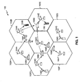
- FIG. 1 serves as an example of a communications system 100 that supports a number of users and is capable of implementing at least some aspects of the embodiments discussed herein. Any of a variety of algorithms and methods may be used to schedule transmissions in system 100.
- System 100 provides communication for a number of cells 102A-102G, each of which is serviced by a corresponding base station 104A-104G, respectively.
- some of the base stations 104 have multiple receive antennas and others have only one receive antenna.
- some of the base stations 104 have multiple transmit antennas, and others have single transmit antennas.
- Terminals 106 in the coverage area may be fixed (i.e., stationary) or mobile. As shown in FIG. 1 , various terminals 106 are dispersed throughout the system. Each terminal 106 communicates with at least one and possibly more base stations 104 on the downlink and uplink at any given moment depending on, for example, whether soft handoff is employed or whether the terminal is designed and operated to (concurrently or sequentially) receive multiple transmissions from multiple base stations. Soft handoff in CDMA communications systems is well known in the art and is described in detail in U.S. Patent No. 5,101,501 , entitled "Method and System for Providing a Soft Handoff in a CDMA Cellular Telephone System", which is assigned to the assignee of the present invention.
- the downlink refers to transmission from the base station 104 to the terminal 106
- the uplink refers to transmission from the terminal 106 to the base station 104.
- some of terminals 106 have multiple receive antennas and others have only one receive antenna.
- base station 104A transmits data to terminals 106A and 106J on the downlink
- base station 104B transmits data to terminals 106B and 106J
- base station 104C transmits data to terminal 106C, and so on.
- FIG. 2 is a block diagram of the base station 202 and mobile station 204 in a communications system 100.
- the base station 202 is in wireless communication with the mobile station 204.
- the base station 202 transmits signals to mobile stations 204 that receive the signals.
- mobile stations 204 may also transmit signals to the base station 202.
- FIG. 3 is a block diagram of the base station 202 and mobile station 204 illustrating the downlink 302 and the uplink 304.
- the downlink 302 refers to transmissions from the base station 202 to the mobile station 204
- the uplink 304 refers to transmissions from the mobile station 204 to the base station 202.
- FIG. 4 is a block diagram of the channels in an embodiment of the downlink 302.
- the downlink 302 includes the pilot channel 402, the sync channel 404, the paging channel 406 and the traffic channel 408.
- the downlink 302 illustrated is only one possible embodiment of a downlink 302 and it will be appreciated that other channels may be added or removed from the downlink 302.
- each base station 202 transmits pilot 402, sync 404, paging 406 and forward traffic 408 channels to its users.
- the pilot channel 402 is an unmodulated, direct-sequence spread spectrum signal transmitted continuously by each base station 202.
- the pilot channel 402 allows each user to acquire the timing of the channels transmitted by the base station 202, and provides a phase reference for coherent demodulation.
- the pilot channel 402 also provides a means for signal strength comparisons between base stations 202 to determine when to hand off between base stations 202 (such as when moving between cells 102).
- the sync channel 404 conveys timing and system configuration information to the mobile station 204.
- the paging channel 406 is used to communicate with mobile stations 204 when they are not assigned to a traffic channel 408.
- the paging channel 406 is used to convey pages, that is, notifications of incoming calls, to the mobile stations 204.
- the traffic channel 408 is used to transmit user data and voice. Signaling messages are also sent over the traffic channel 408.
- FIG. 5 is a block diagram of the channels in an embodiment of the uplink 304.
- the uplink 304 may include a pilot channel 502, an access channel 504 and a traffic channel 506.
- the uplink 304 illustrated is only one possible embodiment of an uplink and it will be appreciated that other channels may be added or removed from the uplink 304.
- the uplink 304 of FIG. 5 includes a pilot channel 502.
- 3G third-generation
- 3G third-generation
- the mobile station 204 transmits a Reverse Link Pilot Channel (R-PICH) that the base station 202 uses for initial acquisition, time tracking, rake-receiver coherent reference recovery, and power control measurements.
- R-PICH Reverse Link Pilot Channel
- systems and methods herein are applicable to pilot signals on the downlink 302 and on the uplink 304.
- the access channel 504 is used by the mobile station 204 to communicate with the base station 202 when the mobile 204 does not have a traffic channel 506 assigned.
- the uplink traffic channel 506 is used to transmit user data and voice. Signaling messages are also sent over the uplink traffic channel 506.
- FIG. 6 An embodiment of a mobile station 204 is shown in a subscriber unit system 600 illustrated in the functional block diagram of FIG. 6 .
- the system 600 includes a processor 602 which controls operation of the system 600.
- the processor 602 may also be referred to as a CPU.
- Memory 604 which may include both read-only memory (ROM) and random access memory (RAM), provides instructions and data to the processor 602.
- a portion of the memory 604 may also include non-volatile random access memory (NVRAM).
- NVRAM non-volatile random access memory
- the system 600 which is typically embodied in a wireless communication device such as a cellular telephone, also includes a housing 606 that contains a transmitter 608 and a receiver 610 to allow transmission and reception of data, such as audio communications, between the system 600 and a remote location, such as a cell site controller or base station 202.
- the transmitter 608 and receiver 610 may be combined into a transceiver 612.
- An antenna 614 is attached to the housing 606 and electrically coupled to the transceiver 612. Additional antennas (not shown) may also be used.
- the operation of the transmitter 608, receiver 610 and antenna 614 is well known in the art and need not be described herein.
- the system 600 also includes a signal detector 616 used to detect and quantify the level of signals received by the transceiver 612.
- the signal detector 616 detects such signals as total energy, pilot energy per pseudonoise (PN) chips, power spectral density, and other signals, as is known in the art.
- PN pseudonoise
- a state changer 626 of the system 600 controls the state of the wireless communication device based on a current state and additional signals received by the transceiver 612 and detected by the signal detector 616.
- the wireless communication device is capable of operating in any one of a number of states.
- the system 600 also includes a system determinator 628 used to control the wireless communication device and determine which service provider system the wireless communication device should transfer to when it determines the current service provider system is inadequate.
- the various components of the system 600 are coupled together by a bus system 630 which may include a power bus, a control signal bus, and a status signal bus in addition to a data bus. However, for the sake of clarity, the various busses are illustrated in FIG. 6 as the bus system 630.
- the system 600 may also include a digital signal processor (DSP) 607 for use in processing signals.
- DSP digital signal processor
- the methods disclosed herein for using an adaptive equalizer in a communication receiver may be implemented in an embodiment of a subscriber unit 600.
- the disclosed systems and methods may also be implemented in other communication systems with a receiver, such as a base station 202. If a base station 202 is being used to implement the disclosed systems and methods, the functional block diagram of FIG. 6 may also be used to describe components in a functional block diagram of a base station 202.
- FIG. 7 is a functional block diagram illustrating the transmission of a wireless signal.
- the wireless signal includes a pilot channel 702 and other orthogonal channels 704. Additional non-orthogonal channels 706 may also be included in the wireless signal. Examples of non-orthogonal channels include the synchronization channel (SCH), channels scrambled by the secondary scrambling code (SSC) in WCDMA, and channels spread by quasi-orthogonal sequences (QOS) in cdma2000.
- SCH synchronization channel
- SSC secondary scrambling code
- QOS quasi-orthogonal sequences
- the orthogonal channels are provided to an orthogonal spreading component 708. Both the orthogonal and non-orthogonal channels are then provided to a channel gain component 710, which adds a gain for the channel. The outputs from the channel gain components 710 are summed together as shown by the summer 712. As shown in FIG. 7 , the non-orthogonal channel may be time-division multiplexed (TDM) 711. In other embodiments, one or more of the orthogonal channels may be time-division multiplexed.
- TDM time-division multiplexed
- the non-orthogonal channels 706 do not have orthogonal spreading components. Some non-orthogonal channels 706 (e.g., the synchronization channel) may be fed directly into the channel gain component 710. Other non-orthogonal channels 706 (e.g., channels spread by quasi-orthogonal sequences in cdma2000) are spread in a non-orthogonal way and then fed into the channel gain component 710. The output of the channel gain component 710 is summed with the summer 712.
- the summed signal is fed into the pseudorandom noise (PN) scrambling component 714.
- a baseband filter 716 takes the output from the PN scrambling component 714 and provides the filtered output 723 to a transmitter 718.
- the transmitter 718 includes an antenna 720. The wireless signal then enters the radio channel 722.
- the functional block diagram of FIG. 7 illustrating the transmission of a wireless signal may be implemented in various components.
- the base station 202 embodies one form of the block diagram illustrated in FIG. 7 .
- the mobile station 204 also implements a form of the transmission block diagram.
- FIG. 8 is a functional block diagram illustrating the reception of a wireless signal 801.
- a receiver 802 receives the wireless signal 801 through the use of an antenna 804.
- the received signal contains a distorted version of the transmitted pilot channel.
- the received signal is fed into a matched filter 806 that is matched to the impulse response of the baseband filter in the transmitter.
- the output 808 from the matched filter 806 still includes all of the different channels that were transmitted.
- the output 808 of the matched filter 806 is provided to a channel estimation and combination component 807, which performs channel estimation and combining on the signal output 808 from the matched filter 806.
- the channel estimation and combination component 807 includes a rake receiver front end, a channel estimator, and a combiner. The channel estimation and combination component 807 will be more fully discussed below in relation to FIG. 10 .
- the output 809 of the channel estimation and combination component 807 is input to an equalizer 810.
- the equalizer 810 corrects for distortions and generates an estimate of the transmitted signal.
- the equalizer 810 also handles time-varying channel conditions.
- the equalizer 810 includes a filter implemented through use of a number of equalizer taps 811. The taps may be equispaced or non-equispaced.
- the equalizer output 812 is provided to the PN descrambling 814 and despreading 816 components.
- the traffic channel 818 is output from the despreading component 816 and is then decoded by a decoding component 820.
- the pilot channel 702 and the other channels 704 are also output from the despreading component 816.
- the despreading component 816 extracts the pilot channel 702 and the other channels and provides separate estimates for the pilot channel and other channels. The various channels are then available for further processing 820.
- An adaptive algorithm component 822 adapts the equalizer 810.
- the estimated pilot 824 is provided by the despreading component 816 to the adaptive algorithm component 822.
- the adaptive algorithm component 822 has a-priori knowledge of the transmitted pilot channel. In wireless communication systems, it is common to transmit a sequence of a-priori known symbols on the pilot channel.
- the estimated pilot 824 input to the adaptive algorithm component 822 may be a code division multiplexed (CDM) pilot.
- the adaptive algorithm 822 may update the taps 811 while the receiver 802 is receiving a wireless signal 801 that includes a pilot channel and other channels.
- adaptive equalizers adapt based on signals that include the pilot channel only, the systems and methods disclosed herein may train and adapt even when a pilot channel simultaneously coexists with other channels.
- Additional algorithm parameters 823 may be provided to the adaptive algorithm component 822.
- the known reference signal may be part of the algorithm parameters 823 that are provided to the adaptive algorithm component 822.
- An adaptation step size may also be included as part of the algorithm parameters 823.
- the algorithm parameters 823 will vary as will be appreciated by those skilled in the art.
- the adaptive algorithm component 822 continues to adapt the equalizer 810 to provide an estimate of the transmitted signal and to enable the equalizer 810 to change as needed.
- the adaptive algorithm component 822 updates the equalizer filter weights 826 that are used by the equalizer 810.
- the weights 826 correspond to the equalizer taps 811.
- the complex baseband analog signal 723 to be transmitted from the baseband filter 716 in FIG. 7 may be written as shown in Formula 1.
- the variables and parameters in Formula 1 are given in Table 1.
- OVSF stands for orthogonal variable spreading factor.
- OVSF codes are also referred to as spreading codes.
- a function for the real attenuation of path i is shown in Formula 2.
- the propagation delay of path i is shown in Formula 3.
- the complex attenuation of path i is shown in Formula 4.
- the term f c is the carrier frequency.
- the parameter d 0 is the nominal distance.
- the term c is the velocity of light.
- the output 808 of the matched filter 806 may be expressed as shown in Formula 7.
- the expression of x l [ m ] in Formula 7 represents the digital samples at Cx ⁇ after matching filtering and also represents the input samples to the channel estimation and combination component 807.
- the variables and parameters in Formula 7 are given in Table 2.
- the signal timing needs to be offset by the path delays. This is termed as the equalizer time offset.
- the pulse shaping filter mentioned in Table 2 is sometimes referred to as the baseband transmit filter.
- This output 824 from the despreading component 816 is input into the adaptive algorithm component 822 that adapts the equalizer 810.
- the input 824 to the adaptive algorithm 822 is an estimate of the CDM pilot.
- Various adaptive algorithms may be used to adapt the equalizer 810 taps 811.
- An iterative algorithm may be used to adapt the equalizer.
- Various iterative algorithms may be used.
- One possible algorithm that may be used is the Least Mean Square (LMS) algorithm.
- Another possible algorithm that may be used is the Recursive Least Squares (RLS) algorithm.
- a Kalman filter may also be used.
- Non-iterative algorithms may also be used.
- Those skilled in the art will appreciate that other adaptive algorithms may also be used to adapt the equalizer 810 taps 811.
- the input q[k] to the equalizer may be written as shown below.
- the term r[m] is the output of the combiner at Cx ⁇ .
- the term ⁇ i is the channel estimate for finger i.
- the term ⁇ is the finger timing offset.
- the received pilot symbol and the known reference signal are used to update the equalizer taps 811 based on an adaptive algorithm 822.
- An implementation is shown in FIG. 8 .
- the components of signal vector q ⁇ k may be written as q [ k ; m ], with m denoting the component index.
- w ⁇ ⁇ k + 1 w ⁇ k + ⁇ ⁇ e ⁇ k ⁇ q ⁇ k
- the equalizer 810 may be implemented by a Finite Impulse Response (FIR) filter.
- FIG. 9 is a block diagram illustrating an implementation of an FIR filter 900. As shown, the input to the filter is x l and the output is x e .
- the input x l includes the present input sample as well as past samples, as indicated by the delay blocks 902.
- the vector w represents the taps of the filter.
- the output may be calculated according to the equation shown in Formula 9.
- the equation of Formula 9 may be written in matrix form as shown in Formula 10.
- equalizer 810 Other components may be used within the equalizer 810 besides an FIR filter. For example, an Infinite Impulse Response (IIR) may be used. In addition, the filtering may be performed in the frequency domain.
- IIR Infinite Impulse Response
- FIG. 10 is a block diagram of an embodiment of a channel estimation and combination component 807.
- the channel estimation and combination component 807 includes a rake receiver front end 1002 as known by those skilled in the art.
- the rake receiver front end 1002 includes a plurality of fingers 1004.
- Each finger 1004 is associated with a multipath component of the signal and has an associated timing.
- the output of each finger 1004 is provided to a channel coefficient estimation component 1006 within a channel estimator 1005.
- Each channel coefficient estimation component 1006 estimates the channel for the corresponding timing.
- All of the outputs from the fingers 1004 are combined by a combiner 1008 based on the channel estimates and timing from all fingers 1004.
- the combiner 1008 may perform maximal ratio combining.
- the output 809 of the combiner 1008 is provided to the equalizer 810 for equalization.
- FIG. 11 is a flow diagram of a method 1100 for using an adaptive equalizer 810 when receiving a wireless signal by a mobile station 204.
- the method of FIG. 11 may also be used by a base station 202 and other types of receivers in a wireless communication system 100.
- a wireless signal is received 1102 that includes a pilot 402 and other channels.
- the other channels may include a variety of channels including, but not limited to, traffic 408, sync 404 and paging 406 channels. Other channels may also be included in the received wireless signal.
- the pilot and other channels may be transmitted continuously. In addition, the pilot and other channels may not be transmitted continuously.
- the method 1100 were being implemented by a base station 202, fewer channels would be included.
- the wireless signal were being received by a base station 202, the wireless signal may include a pilot, traffic and access channels.
- the method 1100 may easily be adapted for use in various receivers in wireless communication systems 100.
- the received signal is filtered 1104 using the matched filter 806.
- the match filter output 808 is processed 1105 by the channel estimation and combination component 807.
- the output 809 of the channel estimation and combination component 807 is provided to an equalizer 810 for equalization 1106.
- the equalizer 810 corrects for distortions and generates an estimate of the transmitted signal and also handles time-varying channel conditions.
- the equalizer 810 includes a filter implemented through use of a number of taps 811 represented by w herein.
- the equalizer 810 loads the current values of the taps 811. If the equalizer taps 811 are updated, the equalizer 810 may use the updated values of the taps 811. Those skilled in the art will appreciate the various ways in which the equalizer 810 may be made aware of new values of the taps 811 being available.
- the equalizer output 812 is provided to the PN descrambling component 814 wherein PN descrambling is performed 1108. Then despreading is performed 1110 to obtain estimates for the pilot and other channels.
- the steps in FIG. 11 may be performed continually while the method 1100 is in operation.
- the method 1100 may continue to receive 1102 the wireless signal, may continue to filter 1104 using the matched filter 806 and may perform the remaining steps shown 1105, 1106, 1108, 1110 and 1112 in the main processing loop in parallel.
- the adaptive algorithm 822 takes the estimated pilot from the component 816 and uses it in the adaptive process.
- a determination 1114 is made as to whether the equalizer 810 should be updated/adapted.
- Different settings may be made for adapting the equalizer 810.
- the method may be configured to adapt the equalizer taps 811 every pilot symbol interval.
- the method may be configured to adapt the equalizer taps 811 once every Nth pilot symbol interval, where N is a positive integer.
- the value of N may be static or it may be dynamic.
- the method may be configured to adapt the equalizer taps 811 multiple times every pilot symbol interval. It will be appreciated by those skilled in the art that, depending on the environment, it may be necessary to adapt the equalizer taps 811 more or less frequently. For example, in low velocity situations, the taps 811 may not need to be adapted and updated as often as when the system is being used in high velocity situations.
- the pilot symbol estimate is input 1116 into the adaptive algorithm 822 until the adaptive algorithm 822 has completed.
- Various methods may be used to determine when the adaptive algorithm 822 is to discontinue operating. For example, the adaptive algorithm 822 may operate until the taps 811 have converged. Alternatively, the adaptive algorithm 822 may operate for a certain period of time. Furthermore, the adaptive algorithm 822 may start adaptation when channel conditions change. Those skilled in the art will appreciate that other methods may be used to determine when the adaptive algorithm 822 is to discontinue operating.
- the tap values 811 are updated 1118. The other channel(s) are then recovered or decoded 1112.
- the components illustrated may be used in a base station 202 to estimate the pilot channel. It is to be understood that the inventive principles herein may be used with a variety of components to estimate a pilot whether the pilot is being received by a mobile station 204, a base station 202, or any other component in a wireless communications system 100.
- a mobile station 204 is an exemplary embodiment of the systems and methods but it is understood that the systems and methods may be used in a variety of other contexts.
- FIG. 12 is a flow diagram of a method 1200 for processing a wireless signal using the channel estimation and combination component 807.
- the method 1200 begins when the output 808 of the matched filter 806 is received 1202.
- the output 808 of the matched filter 806 includes a plurality of multipath signals.
- Multipath signals are different versions of the same wireless signal that are generated by reflections from structures and natural formations. Multipath signals are temporally offset from one another.
- Each finger 1004 of the channel estimation and combination component 807 is then assigned 1204 and time aligned to a multipath signal within the output 808.
- the fingers 1004 perform PN descrambling 1206 and pilot despreading to obtain pilot symbol estimates from each assigned finger 1004.
- the pilot symbol estimates obtained from the different fingers 1004 are then used to perform 1208 channel estimation.
- each channel estimation component 1006 performs channel estimation for one finger 1004.
- the outputs from the various fingers 1004 are combined 1210 into one signal based on the channel estimation 1006 and timing.
- the combined signal is provided 1212 to the equalizer 810.
- DSP digital signal processor
- ASIC application specific integrated circuit
- FPGA field programmable gate array
- a general purpose processor may be a microprocessor, but in the alternative, the processor may be any conventional processor, controller, microcontroller, or state machine.
- a processor may also be implemented as a combination of computing devices, e.g., a combination of a DSP and a microprocessor, a plurality of microprocessors, one or more microprocessors in conjunction with a DSP core, or any other such configuration.
- a software module may reside in RAM memory, flash memory, ROM memory, EPROM memory, EEPROM memory, registers, hard disk, a removable disk, a CD-ROM, or any other form of storage medium known in the art.
- An exemplary storage medium is coupled to the processor such the processor may read information from, and write information to, the storage medium.
- the storage medium may be integral to the processor.
- the processor and the storage medium may reside in an ASIC.
- the ASIC may reside in a user terminal.
- the processor and the storage medium may reside as discrete components in a user terminal.
- the methods disclosed herein comprise one or more steps or actions for achieving the described method.
- the method steps and/or actions may be interchanged with one another without departing from the scope of the present invention.
- the order and/or use of specific steps and/or actions may be modified without departing from the scope of the present invention.
Landscapes
- Engineering & Computer Science (AREA)
- Computer Networks & Wireless Communication (AREA)
- Signal Processing (AREA)
- Cable Transmission Systems, Equalization Of Radio And Reduction Of Echo (AREA)
- Mobile Radio Communication Systems (AREA)
- Dc Digital Transmission (AREA)
- Filters That Use Time-Delay Elements (AREA)
- Noise Elimination (AREA)
Applications Claiming Priority (3)
| Application Number | Priority Date | Filing Date | Title |
|---|---|---|---|
| US368892 | 2003-02-18 | ||
| US10/368,892 US20040161057A1 (en) | 2003-02-18 | 2003-02-18 | Communication receiver with a rake-based adaptive equalizer |
| PCT/US2004/004673 WO2004075432A1 (en) | 2003-02-18 | 2004-02-17 | Communication receiver with a rake-based adaptive equalizer |
Publications (2)
| Publication Number | Publication Date |
|---|---|
| EP1595339A1 EP1595339A1 (en) | 2005-11-16 |
| EP1595339B1 true EP1595339B1 (en) | 2009-10-21 |
Family
ID=32850235
Family Applications (1)
| Application Number | Title | Priority Date | Filing Date |
|---|---|---|---|
| EP04711853A Expired - Lifetime EP1595339B1 (en) | 2003-02-18 | 2004-02-17 | Communication receiver with a rake-based adaptive equalizer |
Country Status (16)
| Country | Link |
|---|---|
| US (1) | US20040161057A1 (pt) |
| EP (1) | EP1595339B1 (pt) |
| JP (1) | JP4559409B2 (pt) |
| KR (1) | KR101068058B1 (pt) |
| CN (1) | CN100542062C (pt) |
| AT (1) | ATE446616T1 (pt) |
| AU (1) | AU2004213985C1 (pt) |
| BR (1) | BRPI0407540A (pt) |
| CA (1) | CA2516114A1 (pt) |
| DE (1) | DE602004023695D1 (pt) |
| IL (1) | IL170144A (pt) |
| MX (1) | MXPA05008773A (pt) |
| RU (1) | RU2349048C2 (pt) |
| TW (1) | TW200501605A (pt) |
| UA (1) | UA88605C2 (pt) |
| WO (1) | WO2004075432A1 (pt) |
Families Citing this family (21)
| Publication number | Priority date | Publication date | Assignee | Title |
|---|---|---|---|---|
| US7257377B2 (en) * | 2003-02-18 | 2007-08-14 | Qualcomm, Incorporated | Systems and methods for improving channel estimation |
| US7272176B2 (en) | 2003-02-18 | 2007-09-18 | Qualcomm Incorporated | Communication receiver with an adaptive equalizer |
| GB0615068D0 (en) * | 2006-07-28 | 2006-09-06 | Ttp Communications Ltd | Digital radio systems |
| KR100848000B1 (ko) * | 2007-02-20 | 2008-07-23 | 에스케이 텔레콤주식회사 | 위성 방송 수신 시스템 및 수신 방법 |
| US7864836B1 (en) | 2007-10-31 | 2011-01-04 | Samsung Electronics Co., Ltd. | Adaptive orthogonal frequency division multiplexing (OFDM) equalizers, OFDM receivers including the same, and methods thereof |
| US8009722B2 (en) * | 2007-12-12 | 2011-08-30 | Telefonaktiebolaget Lm Ericsson (Publ) | Multi-pass parameter estimation for G-Rake receiver |
| CN101547021B (zh) * | 2008-03-28 | 2012-08-29 | 凌阳电通科技股份有限公司 | 均衡装置与使用其的接收器 |
| CN101572562B (zh) * | 2008-05-04 | 2013-03-20 | 凌阳电通科技股份有限公司 | 消除干扰的方法 |
| KR101597090B1 (ko) * | 2008-06-19 | 2016-02-24 | 삼성전자주식회사 | 이동통신 시스템의 수신 장치 및 방법 |
| CN101478330B (zh) * | 2009-01-09 | 2012-08-08 | 重庆金美通信有限责任公司 | 超短波高速电台快速自适应均衡模块及其方法 |
| CN101527972B (zh) * | 2009-04-17 | 2011-01-05 | 凌阳电通科技股份有限公司 | 群集信道下的等化装置与等化方法 |
| US8670432B2 (en) * | 2009-06-22 | 2014-03-11 | Qualcomm Incorporated | Methods and apparatus for coordination of sending reference signals from multiple cells |
| KR20110018143A (ko) * | 2009-08-17 | 2011-02-23 | 삼성전자주식회사 | 이동통신 시스템에서 등화기 수신기 및 방법 |
| WO2014006449A1 (en) * | 2012-07-03 | 2014-01-09 | Freescale Semiconductor, Inc. | A communication device for wideband code division multiple access communication (w-cdma) system, a method for use therein and an associated semiconductor device |
| US8848775B2 (en) * | 2012-08-29 | 2014-09-30 | Intel Mobile Communications GmbH | Circuit for signal processing and method performed by such circuit |
| US9210106B2 (en) | 2013-07-02 | 2015-12-08 | Freescale Semiconductor, Inc. | Communication device for wideband code division multiple access communication (W-CDMA) system, a method for use therein and an associated semiconductor device |
| RU2649799C2 (ru) * | 2015-03-23 | 2018-04-04 | Федеральное государственное бюджетное образовательное учреждение высшего профессионального образования "Воронежский государственный технический университет" | Устройство для изменения частоты дискретизации в многоканальных цифровых приемниках |
| EA038803B1 (ru) * | 2017-12-25 | 2021-10-21 | Федеральное государственное унитарное предприятие "Всероссийский научно-исследовательский институт автоматики им. Н.Л. Духова" | Способ адаптивной цифровой фильтрации импульсных помех и фильтр для его реализации |
| RU2702258C1 (ru) * | 2018-06-26 | 2019-10-07 | Общество с ограниченной ответственностью "РВ-СИСТЕМС" (ООО "РВ-СИСТЕМС") | Способ ортогонального частотного уплотнения и его реализующее устройство |
| CN111919424A (zh) * | 2018-07-02 | 2020-11-10 | 拉姆伯斯公司 | 利用早期高阶符号检测用于判决反馈均衡的方法和电路 |
| CN113119106A (zh) * | 2021-03-04 | 2021-07-16 | 广州机械科学研究院有限公司 | 基于鼠标的机器人位姿控制方法、系统、装置及介质 |
Family Cites Families (48)
| Publication number | Priority date | Publication date | Assignee | Title |
|---|---|---|---|---|
| US5101501A (en) * | 1989-11-07 | 1992-03-31 | Qualcomm Incorporated | Method and system for providing a soft handoff in communications in a cdma cellular telephone system |
| US5297165A (en) * | 1990-07-06 | 1994-03-22 | Nippon Telegraph And Telephone Corporation | Equalizer for radio receive signal |
| JP3093243B2 (ja) * | 1990-07-12 | 2000-10-03 | 株式会社東芝 | 移動無線通信システム |
| DE4108806C1 (pt) * | 1991-03-18 | 1992-01-30 | Litef Gmbh, 7800 Freiburg, De | |
| US5402496A (en) * | 1992-07-13 | 1995-03-28 | Minnesota Mining And Manufacturing Company | Auditory prosthesis, noise suppression apparatus and feedback suppression apparatus having focused adaptive filtering |
| JP2663820B2 (ja) * | 1992-12-28 | 1997-10-15 | 日本電気株式会社 | 判定帰還形等化器 |
| US5572552A (en) * | 1994-01-27 | 1996-11-05 | Ericsson Ge Mobile Communications Inc. | Method and system for demodulation of downlink CDMA signals |
| WO1995034139A1 (en) * | 1994-06-03 | 1995-12-14 | Motorola Inc. | Method and apparatus for subscriber power level adjustment in a communication system |
| DE69534987T2 (de) * | 1994-06-23 | 2006-09-21 | Ntt Docomo Inc. | CDMA Demodulationsschaltung und Demodulationsverfahren |
| US5734966A (en) * | 1995-01-20 | 1998-03-31 | Diablo Research Corporation | Wireless communication system for adapting to frequency drift |
| IT1273963B (it) * | 1995-02-24 | 1997-07-11 | Alcatel Italia | Metodo e circuiti di equalizzazione a spaziatura frazionata |
| JP2705623B2 (ja) * | 1995-03-22 | 1998-01-28 | 日本電気株式会社 | ダイバーシチ送受信方法及び送受信機 |
| US5648983A (en) * | 1995-04-24 | 1997-07-15 | Lucent Technologies Inc. | CDMA rake receiver with sub-chip resolution |
| US5636244A (en) * | 1995-07-26 | 1997-06-03 | Motorola, Inc. | Method and apparatus for initializing equalizer coefficents using peridioc training sequences |
| US6240129B1 (en) * | 1997-07-10 | 2001-05-29 | Alcatel | Method and windowing unit to reduce leakage, fourier transformer and DMT modem wherein the unit is used |
| JP3180725B2 (ja) | 1997-08-05 | 2001-06-25 | 日本電気株式会社 | 分布帰還型半導体レーザ |
| JP2991170B2 (ja) * | 1997-10-01 | 1999-12-20 | 日本電気株式会社 | Cdma受信装置および方法 |
| US6097763A (en) * | 1997-10-31 | 2000-08-01 | Pairgain Technologies, Inc. | MMSE equalizers for DMT systems with cross talk |
| US6175588B1 (en) * | 1997-12-30 | 2001-01-16 | Motorola, Inc. | Communication device and method for interference suppression using adaptive equalization in a spread spectrum communication system |
| JP3952335B2 (ja) * | 1998-03-10 | 2007-08-01 | ソニー株式会社 | 受信方法及び受信装置 |
| US6577690B1 (en) * | 1998-06-25 | 2003-06-10 | Silicon Automation Systems Limited | Clock recovery in multi-carrier transmission systems |
| US6122015A (en) * | 1998-12-07 | 2000-09-19 | General Electric Company | Method and apparatus for filtering digital television signals |
| US6507602B1 (en) * | 1999-01-07 | 2003-01-14 | Ericsson, Inc. | Smoothing receiver channel estimates using spectral estimation |
| US6526093B1 (en) * | 1999-03-04 | 2003-02-25 | Mitsubishi Electric Research Laboratories, Inc | Method and apparatus for equalizing a digital signal received via multiple transmission paths |
| EP1157474A1 (en) * | 1999-03-10 | 2001-11-28 | Nokia Mobile Phones Ltd. | Unsupervised adaptive chip separation filter for cdma terminal |
| FI112831B (fi) * | 1999-04-28 | 2004-01-15 | Nokia Corp | Menetelmä kanavaestimaatin muodostamiseksi ja vastaanotin |
| US6466616B1 (en) * | 1999-07-02 | 2002-10-15 | Telefonaktiebolaget Lm Ericsson (Publ) | Power efficient equalization |
| US6496706B1 (en) * | 1999-07-23 | 2002-12-17 | Qualcomm Incorporated | Method and system for transmit gating in a wireless communication system |
| KR100500810B1 (ko) * | 1999-10-29 | 2005-07-12 | 마츠시타 덴끼 산교 가부시키가이샤 | 파형 등화 제어 장치 |
| EP1130792A1 (en) * | 2000-03-03 | 2001-09-05 | Lucent Technologies Inc. | A method and rake receiver for phasor estimation in communication systems |
| US6314131B1 (en) * | 2000-03-24 | 2001-11-06 | Cadence Design Systems, Inc. | Method and system for channel estimation using multi-slot averaged interpolation |
| KR100452860B1 (ko) * | 2000-06-20 | 2004-10-14 | 삼성전자주식회사 | 훈련 신호를 이용한 적응 등화기용 필터 탭 길이 조정장치 및 방법 |
| US6763061B1 (en) * | 2000-07-31 | 2004-07-13 | 3Com Corporation | Frequency domain technique for narrowband noise cancellation in DMT receivers |
| US6574269B1 (en) * | 2000-11-21 | 2003-06-03 | Bbnt Solutions Llc | Asymmetric orthogonal codes for wireless system receivers with multiplication-free correlators |
| RU2192709C2 (ru) * | 2000-11-30 | 2002-11-10 | Гармонов Александр Васильевич | Способ приема многолучевых сигналов в системе радиосвязи с кодовым разделением каналов и устройство для его реализации |
| US7050419B2 (en) * | 2001-02-23 | 2006-05-23 | Terayon Communicaion Systems, Inc. | Head end receiver for digital data delivery systems using mixed mode SCDMA and TDMA multiplexing |
| US7158558B2 (en) * | 2001-04-26 | 2007-01-02 | Interuniversitair Microelektronica Centrum (Imec) | Wideband multiple access telecommunication method and apparatus |
| US6628707B2 (en) * | 2001-05-04 | 2003-09-30 | Radiant Networks Plc | Adaptive equalizer system for short burst modems and link hopping radio networks |
| US6956893B2 (en) * | 2001-08-20 | 2005-10-18 | Motorola, Inc. | Linear minimum mean square error equalization with interference cancellation for mobile communication forward links utilizing orthogonal codes covered by long pseudorandom spreading codes |
| US6944244B2 (en) * | 2001-09-18 | 2005-09-13 | Thomson Licensing S.A. | Mechanism for OFDM equalizer tap initialization using an adaptive algorithm |
| CA2415170C (en) * | 2001-12-28 | 2008-07-15 | Ntt Docomo, Inc. | Receiver, transmitter, communication system, and method of communication |
| US7193983B2 (en) * | 2002-01-17 | 2007-03-20 | Agency For Science, Technology And Research | Path diversity equalization CDMA downlink receiver |
| US7061967B2 (en) * | 2002-06-24 | 2006-06-13 | Comsys Communication & Signal Processing Ltd. | Multipath channel tap delay estimation in a CDMA spread spectrum receiver |
| US6987797B2 (en) * | 2002-07-26 | 2006-01-17 | Qualcomm Incorporated | Non-parametric matched filter receiver for wireless communication systems |
| US7161973B2 (en) * | 2002-12-17 | 2007-01-09 | Sbc Properties, L.P. | Pilot aided adaptive minimum mean square interference cancellation and detection |
| US7272176B2 (en) * | 2003-02-18 | 2007-09-18 | Qualcomm Incorporated | Communication receiver with an adaptive equalizer |
| US7085317B2 (en) * | 2003-02-18 | 2006-08-01 | Qualcomm, Inc. | Communication receiver with an adaptive equalizer length |
| US7257377B2 (en) * | 2003-02-18 | 2007-08-14 | Qualcomm, Incorporated | Systems and methods for improving channel estimation |
-
2003
- 2003-02-18 US US10/368,892 patent/US20040161057A1/en not_active Abandoned
-
2004
- 2004-02-17 JP JP2006503647A patent/JP4559409B2/ja not_active Expired - Fee Related
- 2004-02-17 CA CA002516114A patent/CA2516114A1/en not_active Abandoned
- 2004-02-17 RU RU2005129082/09A patent/RU2349048C2/ru not_active IP Right Cessation
- 2004-02-17 BR BRPI0407540-4A patent/BRPI0407540A/pt not_active IP Right Cessation
- 2004-02-17 KR KR1020057015256A patent/KR101068058B1/ko active IP Right Grant
- 2004-02-17 AT AT04711853T patent/ATE446616T1/de not_active IP Right Cessation
- 2004-02-17 MX MXPA05008773A patent/MXPA05008773A/es active IP Right Grant
- 2004-02-17 EP EP04711853A patent/EP1595339B1/en not_active Expired - Lifetime
- 2004-02-17 DE DE602004023695T patent/DE602004023695D1/de not_active Expired - Lifetime
- 2004-02-17 WO PCT/US2004/004673 patent/WO2004075432A1/en active Application Filing
- 2004-02-17 AU AU2004213985A patent/AU2004213985C1/en not_active Ceased
- 2004-02-17 CN CNB2004800045420A patent/CN100542062C/zh not_active Expired - Fee Related
- 2004-02-17 UA UAA200508826A patent/UA88605C2/ru unknown
- 2004-02-18 TW TW093103845A patent/TW200501605A/zh unknown
-
2005
- 2005-08-07 IL IL170144A patent/IL170144A/en not_active IP Right Cessation
Also Published As
| Publication number | Publication date |
|---|---|
| AU2004213985A1 (en) | 2004-09-02 |
| ATE446616T1 (de) | 2009-11-15 |
| IL170144A (en) | 2010-12-30 |
| DE602004023695D1 (de) | 2009-12-03 |
| MXPA05008773A (es) | 2006-03-21 |
| WO2004075432A1 (en) | 2004-09-02 |
| CN1751452A (zh) | 2006-03-22 |
| JP4559409B2 (ja) | 2010-10-06 |
| CA2516114A1 (en) | 2004-09-02 |
| KR20050099628A (ko) | 2005-10-14 |
| RU2005129082A (ru) | 2006-01-27 |
| UA88605C2 (ru) | 2009-11-10 |
| CN100542062C (zh) | 2009-09-16 |
| TW200501605A (en) | 2005-01-01 |
| AU2004213985B2 (en) | 2010-01-28 |
| BRPI0407540A (pt) | 2006-02-14 |
| AU2004213985C1 (en) | 2010-08-19 |
| KR101068058B1 (ko) | 2011-09-28 |
| EP1595339A1 (en) | 2005-11-16 |
| JP2006518165A (ja) | 2006-08-03 |
| RU2349048C2 (ru) | 2009-03-10 |
| IL170144A0 (en) | 2009-02-11 |
| US20040161057A1 (en) | 2004-08-19 |
Similar Documents
| Publication | Publication Date | Title |
|---|---|---|
| US8422544B2 (en) | Communication receiver with an adaptive equalizer | |
| EP1595339B1 (en) | Communication receiver with a rake-based adaptive equalizer | |
| EP2200239A2 (en) | Communication receiver with an adaptive equalizer that uses channel estimation | |
| US7085317B2 (en) | Communication receiver with an adaptive equalizer length |
Legal Events
| Date | Code | Title | Description |
|---|---|---|---|
| PUAI | Public reference made under article 153(3) epc to a published international application that has entered the european phase |
Free format text: ORIGINAL CODE: 0009012 |
|
| 17P | Request for examination filed |
Effective date: 20050817 |
|
| AK | Designated contracting states |
Kind code of ref document: A1 Designated state(s): AT BE BG CH CY CZ DE DK EE ES FI FR GB GR HU IE IT LI LU MC NL PT RO SE SI SK TR |
|
| AX | Request for extension of the european patent |
Extension state: AL LT LV MK |
|
| DAX | Request for extension of the european patent (deleted) | ||
| RIN1 | Information on inventor provided before grant (corrected) |
Inventor name: BLANZ, JOSEF Inventor name: WEI, YONGBIN Inventor name: MALLADI, DURGA PRASAD |
|
| 17Q | First examination report despatched |
Effective date: 20071016 |
|
| GRAP | Despatch of communication of intention to grant a patent |
Free format text: ORIGINAL CODE: EPIDOSNIGR1 |
|
| RTI1 | Title (correction) |
Free format text: COMMUNICATION RECEIVER WITH A RAKE-BASED ADAPTIVE EQUALIZER |
|
| GRAS | Grant fee paid |
Free format text: ORIGINAL CODE: EPIDOSNIGR3 |
|
| GRAA | (expected) grant |
Free format text: ORIGINAL CODE: 0009210 |
|
| AK | Designated contracting states |
Kind code of ref document: B1 Designated state(s): AT BE BG CH CY CZ DE DK EE ES FI FR GB GR HU IE IT LI LU MC NL PT RO SE SI SK TR |
|
| REG | Reference to a national code |
Ref country code: GB Ref legal event code: FG4D |
|
| REG | Reference to a national code |
Ref country code: CH Ref legal event code: EP |
|
| REG | Reference to a national code |
Ref country code: IE Ref legal event code: FG4D |
|
| REF | Corresponds to: |
Ref document number: 602004023695 Country of ref document: DE Date of ref document: 20091203 Kind code of ref document: P |
|
| NLV1 | Nl: lapsed or annulled due to failure to fulfill the requirements of art. 29p and 29m of the patents act | ||
| PG25 | Lapsed in a contracting state [announced via postgrant information from national office to epo] |
Ref country code: SE Free format text: LAPSE BECAUSE OF FAILURE TO SUBMIT A TRANSLATION OF THE DESCRIPTION OR TO PAY THE FEE WITHIN THE PRESCRIBED TIME-LIMIT Effective date: 20091021 Ref country code: FI Free format text: LAPSE BECAUSE OF FAILURE TO SUBMIT A TRANSLATION OF THE DESCRIPTION OR TO PAY THE FEE WITHIN THE PRESCRIBED TIME-LIMIT Effective date: 20091021 Ref country code: ES Free format text: LAPSE BECAUSE OF FAILURE TO SUBMIT A TRANSLATION OF THE DESCRIPTION OR TO PAY THE FEE WITHIN THE PRESCRIBED TIME-LIMIT Effective date: 20100201 Ref country code: PT Free format text: LAPSE BECAUSE OF FAILURE TO SUBMIT A TRANSLATION OF THE DESCRIPTION OR TO PAY THE FEE WITHIN THE PRESCRIBED TIME-LIMIT Effective date: 20100222 |
|
| PGFP | Annual fee paid to national office [announced via postgrant information from national office to epo] |
Ref country code: FR Payment date: 20091103 Year of fee payment: 7 |
|
| PG25 | Lapsed in a contracting state [announced via postgrant information from national office to epo] |
Ref country code: SI Free format text: LAPSE BECAUSE OF FAILURE TO SUBMIT A TRANSLATION OF THE DESCRIPTION OR TO PAY THE FEE WITHIN THE PRESCRIBED TIME-LIMIT Effective date: 20091021 |
|
| PG25 | Lapsed in a contracting state [announced via postgrant information from national office to epo] |
Ref country code: AT Free format text: LAPSE BECAUSE OF FAILURE TO SUBMIT A TRANSLATION OF THE DESCRIPTION OR TO PAY THE FEE WITHIN THE PRESCRIBED TIME-LIMIT Effective date: 20091021 Ref country code: BE Free format text: LAPSE BECAUSE OF FAILURE TO SUBMIT A TRANSLATION OF THE DESCRIPTION OR TO PAY THE FEE WITHIN THE PRESCRIBED TIME-LIMIT Effective date: 20091021 |
|
| PG25 | Lapsed in a contracting state [announced via postgrant information from national office to epo] |
Ref country code: EE Free format text: LAPSE BECAUSE OF FAILURE TO SUBMIT A TRANSLATION OF THE DESCRIPTION OR TO PAY THE FEE WITHIN THE PRESCRIBED TIME-LIMIT Effective date: 20091021 Ref country code: DK Free format text: LAPSE BECAUSE OF FAILURE TO SUBMIT A TRANSLATION OF THE DESCRIPTION OR TO PAY THE FEE WITHIN THE PRESCRIBED TIME-LIMIT Effective date: 20091021 Ref country code: RO Free format text: LAPSE BECAUSE OF FAILURE TO SUBMIT A TRANSLATION OF THE DESCRIPTION OR TO PAY THE FEE WITHIN THE PRESCRIBED TIME-LIMIT Effective date: 20091021 Ref country code: BG Free format text: LAPSE BECAUSE OF FAILURE TO SUBMIT A TRANSLATION OF THE DESCRIPTION OR TO PAY THE FEE WITHIN THE PRESCRIBED TIME-LIMIT Effective date: 20100121 |
|
| PLBE | No opposition filed within time limit |
Free format text: ORIGINAL CODE: 0009261 |
|
| STAA | Information on the status of an ep patent application or granted ep patent |
Free format text: STATUS: NO OPPOSITION FILED WITHIN TIME LIMIT |
|
| PG25 | Lapsed in a contracting state [announced via postgrant information from national office to epo] |
Ref country code: SK Free format text: LAPSE BECAUSE OF FAILURE TO SUBMIT A TRANSLATION OF THE DESCRIPTION OR TO PAY THE FEE WITHIN THE PRESCRIBED TIME-LIMIT Effective date: 20091021 Ref country code: CZ Free format text: LAPSE BECAUSE OF FAILURE TO SUBMIT A TRANSLATION OF THE DESCRIPTION OR TO PAY THE FEE WITHIN THE PRESCRIBED TIME-LIMIT Effective date: 20091021 |
|
| 26N | No opposition filed |
Effective date: 20100722 |
|
| REG | Reference to a national code |
Ref country code: CH Ref legal event code: PL |
|
| PG25 | Lapsed in a contracting state [announced via postgrant information from national office to epo] |
Ref country code: MC Free format text: LAPSE BECAUSE OF NON-PAYMENT OF DUE FEES Effective date: 20100301 Ref country code: LI Free format text: LAPSE BECAUSE OF NON-PAYMENT OF DUE FEES Effective date: 20100228 Ref country code: GR Free format text: LAPSE BECAUSE OF FAILURE TO SUBMIT A TRANSLATION OF THE DESCRIPTION OR TO PAY THE FEE WITHIN THE PRESCRIBED TIME-LIMIT Effective date: 20100122 Ref country code: CH Free format text: LAPSE BECAUSE OF NON-PAYMENT OF DUE FEES Effective date: 20100228 |
|
| PG25 | Lapsed in a contracting state [announced via postgrant information from national office to epo] |
Ref country code: IE Free format text: LAPSE BECAUSE OF NON-PAYMENT OF DUE FEES Effective date: 20100217 |
|
| PG25 | Lapsed in a contracting state [announced via postgrant information from national office to epo] |
Ref country code: IT Free format text: LAPSE BECAUSE OF FAILURE TO SUBMIT A TRANSLATION OF THE DESCRIPTION OR TO PAY THE FEE WITHIN THE PRESCRIBED TIME-LIMIT Effective date: 20091021 |
|
| REG | Reference to a national code |
Ref country code: FR Ref legal event code: ST Effective date: 20111102 |
|
| PG25 | Lapsed in a contracting state [announced via postgrant information from national office to epo] |
Ref country code: FR Free format text: LAPSE BECAUSE OF NON-PAYMENT OF DUE FEES Effective date: 20110228 |
|
| PG25 | Lapsed in a contracting state [announced via postgrant information from national office to epo] |
Ref country code: CY Free format text: LAPSE BECAUSE OF FAILURE TO SUBMIT A TRANSLATION OF THE DESCRIPTION OR TO PAY THE FEE WITHIN THE PRESCRIBED TIME-LIMIT Effective date: 20091021 |
|
| PG25 | Lapsed in a contracting state [announced via postgrant information from national office to epo] |
Ref country code: NL Free format text: LAPSE BECAUSE OF FAILURE TO SUBMIT A TRANSLATION OF THE DESCRIPTION OR TO PAY THE FEE WITHIN THE PRESCRIBED TIME-LIMIT Effective date: 20091021 Ref country code: HU Free format text: LAPSE BECAUSE OF FAILURE TO SUBMIT A TRANSLATION OF THE DESCRIPTION OR TO PAY THE FEE WITHIN THE PRESCRIBED TIME-LIMIT Effective date: 20100422 Ref country code: LU Free format text: LAPSE BECAUSE OF NON-PAYMENT OF DUE FEES Effective date: 20100217 |
|
| PG25 | Lapsed in a contracting state [announced via postgrant information from national office to epo] |
Ref country code: TR Free format text: LAPSE BECAUSE OF FAILURE TO SUBMIT A TRANSLATION OF THE DESCRIPTION OR TO PAY THE FEE WITHIN THE PRESCRIBED TIME-LIMIT Effective date: 20091021 |
|
| REG | Reference to a national code |
Ref country code: DE Ref legal event code: R082 Ref document number: 602004023695 Country of ref document: DE Representative=s name: BARDEHLE PAGENBERG PARTNERSCHAFT MBB PATENTANW, DE Ref country code: DE Ref legal event code: R081 Ref document number: 602004023695 Country of ref document: DE Owner name: QUALCOMM INCORPORATED, SAN DIEGO, US Free format text: FORMER OWNER: QUALCOMM INC., SAN DIEGO, CALIF., US |
|
| PGFP | Annual fee paid to national office [announced via postgrant information from national office to epo] |
Ref country code: GB Payment date: 20200130 Year of fee payment: 17 Ref country code: DE Payment date: 20200115 Year of fee payment: 17 |
|
| REG | Reference to a national code |
Ref country code: DE Ref legal event code: R119 Ref document number: 602004023695 Country of ref document: DE |
|
| GBPC | Gb: european patent ceased through non-payment of renewal fee |
Effective date: 20210217 |
|
| PG25 | Lapsed in a contracting state [announced via postgrant information from national office to epo] |
Ref country code: GB Free format text: LAPSE BECAUSE OF NON-PAYMENT OF DUE FEES Effective date: 20210217 Ref country code: DE Free format text: LAPSE BECAUSE OF NON-PAYMENT OF DUE FEES Effective date: 20210901 |