EP1594697B1 - Verfahren und vorrichtung zum wechseln von druckhülsen in einer druckmaschine - Google Patents
Verfahren und vorrichtung zum wechseln von druckhülsen in einer druckmaschine Download PDFInfo
- Publication number
- EP1594697B1 EP1594697B1 EP04701956A EP04701956A EP1594697B1 EP 1594697 B1 EP1594697 B1 EP 1594697B1 EP 04701956 A EP04701956 A EP 04701956A EP 04701956 A EP04701956 A EP 04701956A EP 1594697 B1 EP1594697 B1 EP 1594697B1
- Authority
- EP
- European Patent Office
- Prior art keywords
- printing
- sleeves
- transport device
- control unit
- arrangement
- Prior art date
- Legal status (The legal status is an assumption and is not a legal conclusion. Google has not performed a legal analysis and makes no representation as to the accuracy of the status listed.)
- Expired - Lifetime
Links
- 238000000034 method Methods 0.000 title claims abstract description 21
- 238000012546 transfer Methods 0.000 claims description 5
- 238000012545 processing Methods 0.000 abstract description 4
- 238000005096 rolling process Methods 0.000 description 6
- 238000007774 anilox coating Methods 0.000 description 5
- 241001310793 Podium Species 0.000 description 1
- 238000013459 approach Methods 0.000 description 1
- 230000006835 compression Effects 0.000 description 1
- 238000007906 compression Methods 0.000 description 1
- 230000008878 coupling Effects 0.000 description 1
- 238000010168 coupling process Methods 0.000 description 1
- 238000005859 coupling reaction Methods 0.000 description 1
- 238000013461 design Methods 0.000 description 1
- 238000006073 displacement reaction Methods 0.000 description 1
- NJPPVKZQTLUDBO-UHFFFAOYSA-N novaluron Chemical compound C1=C(Cl)C(OC(F)(F)C(OC(F)(F)F)F)=CC=C1NC(=O)NC(=O)C1=C(F)C=CC=C1F NJPPVKZQTLUDBO-UHFFFAOYSA-N 0.000 description 1
Images
Classifications
-
- B—PERFORMING OPERATIONS; TRANSPORTING
- B41—PRINTING; LINING MACHINES; TYPEWRITERS; STAMPS
- B41F—PRINTING MACHINES OR PRESSES
- B41F13/00—Common details of rotary presses or machines
- B41F13/0016—Storage devices for printing cylinders
-
- B—PERFORMING OPERATIONS; TRANSPORTING
- B41—PRINTING; LINING MACHINES; TYPEWRITERS; STAMPS
- B41P—INDEXING SCHEME RELATING TO PRINTING, LINING MACHINES, TYPEWRITERS, AND TO STAMPS
- B41P2200/00—Printing processes
- B41P2200/10—Relief printing
- B41P2200/12—Flexographic printing
-
- B—PERFORMING OPERATIONS; TRANSPORTING
- B41—PRINTING; LINING MACHINES; TYPEWRITERS; STAMPS
- B41P—INDEXING SCHEME RELATING TO PRINTING, LINING MACHINES, TYPEWRITERS, AND TO STAMPS
- B41P2227/00—Mounting or handling printing plates; Forming printing surfaces in situ
- B41P2227/20—Means enabling or facilitating exchange of tubular printing or impression members, e.g. printing sleeves, blankets
-
- B—PERFORMING OPERATIONS; TRANSPORTING
- B41—PRINTING; LINING MACHINES; TYPEWRITERS; STAMPS
- B41P—INDEXING SCHEME RELATING TO PRINTING, LINING MACHINES, TYPEWRITERS, AND TO STAMPS
- B41P2227/00—Mounting or handling printing plates; Forming printing surfaces in situ
- B41P2227/50—Devices for storing printing plates
-
- B—PERFORMING OPERATIONS; TRANSPORTING
- B41—PRINTING; LINING MACHINES; TYPEWRITERS; STAMPS
- B41P—INDEXING SCHEME RELATING TO PRINTING, LINING MACHINES, TYPEWRITERS, AND TO STAMPS
- B41P2227/00—Mounting or handling printing plates; Forming printing surfaces in situ
- B41P2227/60—Devices for transferring printing plates
Definitions
- the invention relates to a method and a device for changing printing sleeves in a printing press according to the preamble of claims 1 and 8.
- the still unpublished patent application DE 102 23 414 shows a transport device for printing sleeves with a plurality of support pins for receiving the printing sleeves.
- two adjacent support pins have a distance corresponding to the distance of the printing and anilox roller in their setup positions. These two support pins form a row within the transport device.
- the transport device can be coupled to a lifting device fastened to the printing press and thus moved horizontally and vertically relative to the printing press.
- the operator must first equip the transport device with the introduced into the printing press sleeves and the transport device in front of the printing unit in which there are to be replaced printing sleeves, with the help Position the lifting device so that two free support pins are positioned in front of the pressure rollers. Then the pressure sleeves located on the print roller loops can be removed by the operating personnel. Subsequently, the transport device is repositioned to bring the réelleschiebenden printing sleeves in a suitable position for sliding onto the rolling mandrels. Then the pressure sleeves can be pushed. If necessary, the procedure is the same for other printing units.
- the object of the present invention is therefore to propose a method for changing printing sleeves in printing presses, which simplifies the exchange of printing sleeves.
- the arrangement of the pressure sleeves in the transport device is determined by a computing and control unit.
- the arrangement of the pressure sleeves is set up so that at least one compression sleeve receiving device remains free in the transport device.
- the computing and control unit takes into account all relevant printing sleeves, not only those that are to be supplied to the printing press, but also those that must be removed from the printing press and the storage device must be supplied.
- As a basis for the Determination of the arrangement uses the arithmetic and control unit data on the nominal positions of the individual printing sleeves for processing the new print job and data on the current positions of printing sleeves in the printing press. Also, data about the positions of the printing sleeves in the storage device may be known to the computing and control unit.
- the arithmetic and control unit determines the arrangement of the printing sleeves in the transport device such that at least one empty printing sleeve receiving device and the at least one new printing sleeve required for the new printing job are contained in each line.
- One line of the transport device is assigned to a specific printing unit. For each printing unit so at least one empty printing sleeve receiving device is provided.
- the printing sleeve receiving devices arranged in a row can likewise be arranged horizontally. In this case, after the removal of a printing sleeve of a processed print job, the transport device must only be moved horizontally in order to reach a position in which a new printing sleeve can be pushed onto the roller mandrel.
- the arithmetic and control unit determines the arrangement of the printing sleeves in the transport device such that one line of printing sleeve receiving devices remains free and the other lines contain the printing sleeves associated with the respective printing units. In this case, therefore, first all printing sleeves of a printing unit are removed from the rolling mandrels. Then, the transport device is moved vertically, so that the respective printing unit associated new printing sleeves can be brought into a suitable position for the change.
- a display unit a screen may be provided, but are suitable for this purpose, further means for displaying the arrangement, such as prints of a printer.
- the arrangement of the printing sleeves in the transport device determined by the computing and control unit is carried out by the operator.
- the operator removes the corresponding pressure sleeves from the storage device and arranges them in the transport device according to the arrangement shown on the display unit.
- the arithmetic and control unit has interfaces to actuators of the storage and / or transport device and controls them in such a way that they at least partially carry out the transfer between the two aforementioned devices.
- the computing and control unit has access to data that includes the locations of each individual printing sleeve in the storage device.
- the transport device can be equipped with pressure sleeves, for example with the aid of a gripper device, without permutations occurring.
- the printing sleeves removed from the printing press and transported in the transporting device are fed to the storage device, the data containing the positions of the printing sleeves remaining accessible to the computing and control unit.
- a data memory connected to the computing and control unit can be used.
- the computing and control unit has interfaces to actuators of the transport device and / or the printing press and controls them so that they perform the transfer between the two aforementioned devices at least partially.
- a Such control is used for automatic transfer of the transport device to the printing press and back.
- the control may further comprise the coupling and uncoupling of the transport device to and / or from a lifting device and the method of the transport device relative to the printing press.
- the arithmetic and control unit controls the position of the transport device relative to the printing press so that empty Druckhülsenabilityvoriquesen are brought into a removal position to be acted upon by the printing sleeves to be replaced Walzendornen and then the with the new printing sleeves acted upon Druckhülsenabilityvorraumen be brought into the change position.
- the operator can first remove a printing sleeve of the already processed print job from the roller mandrel and postpone it to an empty printing sleeve receiving device.
- the arithmetic and control unit controls the actuators in such a way that the pressure sleeve of the new print job which is to be pushed onto the roller mandrel is in the interchangeable position is brought. This method is carried out for all rolling mandrels from which a pressure sleeve is removed and / or a pressure sleeve to be pushed.
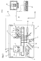
- the single FIGURE shows a printing press which is prepared by the method according to the invention.
- the printing machine 1 comprises two side frames, of which the front side frame 2 can be seen. From the front side frame 2 more printing units are accessible, of which two printing units 3, 4 are exemplified. From the printing unit 3, the two bearing blocks 22 to see that are in the extended position, so that the pressure roller 5 and the anilox roller 6 are accessible.
- the pressure roller 5 consists essentially of the roller mandrel 8 and the pressure sleeve 7 pushed onto it.
- the anilox roller 6 is constructed in the same way.
- the catwalk 10 which is mounted in the pedestal 12, can be moved along the arrow A.
- one of the two stairs 11 can be folded.
- the printing machine further comprises a lifting device 15, with which a transport device 13 can be moved relative to the printing press 1.
- a horizontal movement is made possible by a running rail 17 fastened to the side frame 2.
- a winch 16 which is slidably mounted on the running rail 17.
- the operator can first give the computing and control unit 19 via a keyboard 21 information about the new print job. Subsequently, the computing and control unit calculates the arrangement of the printing sleeves in the transport device 13. Now, the operating personnel 9 in a manner not shown to equip the transport device 13 according to the determined by the computing and control unit 19 arrangement. For this purpose, this arrangement is displayed on the screen 20. Subsequently, the operator 9 goes to the first printing unit 3, from which the printing sleeves 7 must be removed.
- the arithmetic and control unit 19 controls the lifting device 15 via the control line 18 such that initially a free support mandrel 14 of the transport device 13 is brought into a position which allows removal of a pressure sleeve 7 of the roller mandrel 8. After moving the pressure sleeve 7 of the roller mandrel 8 on a support mandrel 14 actuates the operator 9 a button, not shown.
- the computing and control unit 19 now controls the lifting device 15, so that a support mandrel 14, on which there is a new pressure sleeve 7, assumes a change position. After moving this pressure sleeve 7, the operator 9 again actuates the button, not shown.
Landscapes
- Engineering & Computer Science (AREA)
- Mechanical Engineering (AREA)
- Rotary Presses (AREA)
- Inking, Control Or Cleaning Of Printing Machines (AREA)
- Printers Characterized By Their Purpose (AREA)
Description
- Die Erfindung betrifft ein Verfahren und eine Vorrichtung zum Wechseln von Druckhülsen in einer Druckmaschine gemäß des Oberbegriffs der Ansprüche 1 und 8.
- Zur Abwicklung von Druckaufträgen ist es häufig notwendig, die Druckmotive der Druckwalzen einer Druckmaschine zu wechseln. Um diesen Auftragswechsel möglichst schnell und einfach durchführen zu können, werden häufig nur die Druckhülsen, welche die Druckmotive tragen und auf den Walzendornen aufliegen, ausgewechselt.
- Die noch unveröffentlichte Patentanmeldung
DE 102 23 414 zeigt eine Transportvorrichtung für Druckhülsen mit einer Mehrzahl von Tragedornen zur Aufnahme der Druckhülsen. Jeweils zwei benachbarte Tragedorne haben dabei einen Abstand, der dem Abstand der Druck- und Rasterwalze in deren Rüstpositionen entspricht. Diese beiden Tragedorne bilden eine Zeile innerhalb der Transportvorrichtung. Die Transportvorrichtung ist an eine an der Druckmaschine befestigten Hubvorrichtung ankoppelbar und damit relativ zur Druckmaschine horizontal und vertikal verfahrbar. - Soll nun eine Druckhülse gewechselt werden, muss das Bedienpersonal zunächst die Transportvorrichtung mit den in die Druckmaschine einzubringenden Druckhülsen bestücken und die Transportvorrichtung vor dem Druckwerk, in dem sich die zu wechselnden Druckhülsen befinden, mit Hilfe der Hubvorrichtung positionieren, so dass zwei freie Tragedorne vor den Druckwalzen positioniert sind. Dann können die auf den Druckwalzendörnen befindlichen Druckhülsen vom Bedienpersonal abgezogen werden. Anschließend wird die Transportvorrichtung neu positioniert, um die aufzuschiebenden Druckhülsen in eine passende Lage zum Aufschieben auf die Walzendorne zu bringen. Dann können die Druckhülsen aufgeschoben werden. Gegebenenfalls wird für weitere Druckwerke auf gleiche Weise verfahren.
- Bei den beschriebenen Verfahren zum Wechseln von Druckhülsen einer Druckmaschine erfolgt die Bestückung der Transportvorrichtung durch das Bedienpersonal, wobei es keine festgelegte Anordnung der Druckhülsen in der Transportvorrichtung gibt. Das Bedienpersonal muss also selbstständig eine Anordnung der Druckhülsen in der Transportvorrichtung entwerfen, wobei die Anordnung zum Teil ungünstig für den Rüstvorgang ist. Zudem besteht die Gefahr einer fehlerhaften Zuordnung der Druckhülsen zu den Walzendornen.
- Ein Verfahren und eine Vorrichtung gemäß dem Oberbegriff der Ansprüche 1 und 8 ist auch vom Dokument
US 2002/0056392 bekannt. - Die Aufgabe der vorliegenden Erfindung ist es daher, ein Verfahren zum Wechseln von Druckhülsen in Druckmaschinen vorzuschlagen, das das Wechseln von Druckhülsen vereinfacht.
- Erfindungsgemäß wird diese Aufgabe durch die Merkmale des kennzeichnenden Teils der Ansprüche 1 und 8 gelöst.
- Demnach wird die Anordnung der Druckhülsen in der Transportvorrichtung von einer Rechen- und Steuereinheit bestimmt. Die Anordnung der Druckhülsen wird dabei so eingerichtet, dass zumindest eine Druckhülsenaufnahmeeinrichtung in der Transportvorrichtung frei bleibt. Die Rechen- und Steuereinheit berücksichtigt dabei alle relevanten Druckhülsen, also nicht nur diejenigen, die der Druckmaschine zugeführt werden sollen, sondern auch solche, die aus der Druckmaschine abgeführt und der Speichervorrichtung zugeführt werden müssen. Als Grundlage für die Bestimmung der Anordnung verwendet die Rechen- und Steuereinheit Daten über die Sollpositionen der einzelnen Druckhülsen zur Bearbeitung des neuen Druckauftrags sowie Daten über die aktuellen Positionen von Druckhülsen in der Druckmaschine. Auch Daten über die Positionen der Druckhülsen in der Speichervorrichtung können der Rechen- und Steuereinheit bekannt sein.
- Vorteilhafterweise bestimmt die Rechen- und Steuereinheit die Anordnung der Druckhülsen in der Transportvorrichtung derart, dass in jeder Zeile zumindest eine leere Druckhülsenaufnahmevorrichtung und die zumindest eine für den neuen Druckauftrag benötigte neue Druckhülse enthalten sind. Eine Zeile der Transporteinrichtung ist dabei einem bestimmten Druckwerk zugeordnet. Für jedes Druckwerk ist also zumindest eine leere Druckhülsenaufnahmevorrichtung vorgesehen. Ist das Druckwerk beispielsweise horizontal angeordnet, können die in einer Zeile angeordneten Druckhülsenaufnahmevorrichtungen ebenfalls horizontal angeordnet sein. In diesem Fall muss nach dem Abschieben einer Druckhülse eines abgearbeiteten Druckauftrags die Transportvorrichtung nur horizontal verschoben werden, um eine Position zu erreichen, in welcher eine neue Druckhülse auf den Walzendorn aufgeschoben werden kann.
- In einer weiteren bevorzugten Ausführungsform der Erfindung bestimmt die Rechen- und Steuereinheit die Anordnung der Druckhülsen in der Transportvorrichtung derart, dass eine Zeile von Druckhülsenaufnahmevorrichtungen frei bleibt und die anderen Zeilen die den jeweiligen Druckwerken zugeordneten Druckhülsen enthalten. In diesem Fall werden also zunächst alle Druckhülsen eines Druckwerks von den Walzendornen entfernt. Sodann wird die Transportvorrichtung vertikal verschoben, so dass die dem betreffenden Druckwerk zugeordneten neuen Druckhülsen in eine für den Wechsel geeigneten Position gebracht werden können.
- Es ist besonders vorteilhaft, wenn die von einer Rechen- und Steuereinheit bestimmte Anordnung der Druckhülsen in der Transportvorrichtung auf einer Anzeigeeinheit angezeigt wird. Als Anzeigeeinheit kann ein Bildschirm vorgesehen sein, jedoch eignen sich zu diesem Zweck auch weitere Mittel zum Anzeigen der Anordnung, beispielsweise Ausdrucke eines Druckers.
- In einer bevorzugten Ausführungsform der Erfindung wird die von der Rechen- und Steuereinheit bestimmte Anordnung der Druckhülsen in der Transportvorrichtung vom Bedienpersonal vorgenommen. Das Bedienpersonal entnimmt dazu der Speichervorrichtung die entsprechenden Druckhülsen und ordnet diese gemäß der auf der Anzeigeneinheit dargestellten Anordnung in der Transportvorrichtung ein.
- Besonders vorteilhaft ist es, wenn die Rechen- und Steuereinheit über Schnittstellen zu Aktuatoren der Speicher- und/oder Transportvorrichtung verfügt und diese so ansteuert, dass sie den Transfer zwischen den beiden vorgenannten Vorrichtungen zumindest teilweise durchführen. Zu diesem Zweck hat die Rechen- und Steuereinheit Zugang zu Daten, die die Positionen jeder einzelnen Druckhülse in der Speichervorrichtung beinhaltet. Auf diese Weise kann die Transportvorrichtung mit Druckhülsen, beispielsweise mit Hilfe einer Greifervorrichtung, bestückt werden, ohne dass Vertauschungen vorkommen. Auf gleiche Weise werden die aus der Druckmaschine entfernten und in der Transportvorrichtung transportierten Druckhülsen der Speichervorrichtung zugeführt werden, wobei die die Positionen der Druckhülsen beinhaltenden Daten für die Rechen- und Steuereinheit zugänglich bleiben. Hierzu kann ein mit der Rechen- und Steuereinheit verbundener Datenspeicher dienen.
- Vorteilhaft ist weiterhin, wenn die Rechen- und Steuereinheit über Schnittstellen zu Aktuatoren der Transportvorrichtung und/oder der Druckmaschine verfügt und diese so ansteuert, dass sie den Transfer zwischen den beiden vorgenannten Vorrichtungen zumindest teilweise durchführen. Eine derartige Ansteuerung dient dem automatischen Transfer der Transportvorrichtung zur Druckmaschine und zurück. Die Ansteuerung kann weiterhin das An- und Abkoppeln der Transportvorrichtung an und/oder von einer Hubvorrichtung sowie das Verfahren der Transportvorrichtung relativ zur Druckmaschine umfassen.
- In einer bevorzugten Ausführungsform steuert die Rechen- und Steuereinheit aufgrund der von ihr bestimmten Anordnung der Druckhülsen in der Transportvorrichtung die Position der Transportvorrichtung relativ zur Druckmaschine so, dass leere Druckhülsenaufnahmevorrichtungen in eine Entnahmeposition zu den mit den auszuwechselnden Druckhülsen beaufschlagten Walzendornen gebracht werden und anschließend die mit den neuen Druckhülsen beaufschlagten Druckhülsenaufnahmevorrichtungen in die Wechselposition gebracht werden. Bei dieser Vorgehensweise kann das Bedienpersonal zunächst eine Druckhülse des bereits bearbeiteten Druckauftrags von dem Walzendorn entfernen und auf eine leere Druckhülsenaufnahmevorrichtung aufschieben. Hat das Bedienpersonal der Rechen- und Steuereinheit die Beendigung dieser Tätigkeit, beispielsweise über einen Tastendruck, angezeigt, so steuert die Rechen- und Steuereinheit die Aktuatoren derart an, dass die Druckhülse des neuen Druckauftrags, die auf den Walzendorn aufgeschoben werden soll, in die Wechselposition gebracht wird. Dieses Verfahren wird für alle Walzendorne durchgeführt, von welchen eine Druckhülse entfernt und/oder eine Druckhülse aufgeschoben werden soll.
- Die einzige Figur zeigt eine Druckmaschine, die nach dem erfindungsgemäßen Verfahren gerüstet wird.
- Die Druckmaschine 1 umfasst zwei Seitengestelle, von denen das vordere Seitengestell 2 zu sehen ist. Von dem vorderen Seitengestell 2 sind mehrere Druckwerke zugänglich, von denen exemplarisch zwei Druckwerke 3, 4 dargestellt sind. Von dem Druckwerk 3 sind die beiden Lagerböcke 22 zu sehen, die sich in abgerückter Position befinden, so dass die Druckwalze 5 und die Rasterwalze 6 zugänglich sind. Die Druckwalze 5 besteht im wesentlichen aus dem Walzendorn 8 und der darauf aufgeschobenen Druckhülse 7. In gleicher Weise ist die Rasterwalze 6 aufgebaut.
- Um die unteren Druckwerke, von denen nur das Druckwerk 4 gezeigt ist, erreichen zu können, kann der Laufsteg 10, welcher in dem Podest 12 gelagert ist, entlang des Pfeils A verschoben werden. Zusätzlich kann eine der beiden Treppen 11 eingeklappt werden.
- Die Druckmaschine umfasst weiterhin eine Hubvorrichtung 15, mit welcher eine Transportvorrichtung 13 relativ zur Druckmaschine 1 verfahren werden kann. Eine horizontale Bewegung wird durch eine an dem Seitengestell 2 befestigten Laufschiene 17 ermöglicht. Zum Anheben der Transportvorrichtung 13 dient eine Seilwinde 16, die auf der Laufschiene 17 verschieblich gelagert ist.
- Zum Rüsten der Druckmaschine 1 für einen neuen Druckauftrag kann das Bedienpersonal zunächst der Rechen- und Steuereinheit 19 über eine Tastatur 21 Informationen über den neuen Druckauftrag erteilen. Anschließend berechnet die Rechen- und Steuereinheit die Anordnung der Druckhülsen in der Transportvorrichtung 13. Nun muss das Bedienpersonal 9 auf nicht näher dargestellte Weise die Transportvorrichtung 13 gemäß der von der Rechen- und Steuereinheit 19 bestimmten Anordnung bestücken. Zu diesem Zweck wird diese Anordnung auf dem Bildschirm 20 dargestellt. Anschließend begibt sich das Bedienpersonal 9 zum ersten Druckwerk 3, von dem die Druckhülsen 7 entfernt werden müssen. Die Rechen- und Steuereinheit 19 steuert die Hubvorrichtung 15 über die Steuerleitung 18 derart, dass zunächst ein freier Tragedorn 14 der Transportvorrichtung 13 in eine Position gebracht wird, die ein Abziehen einer Druckhülse 7 von dem Walzendorn 8 ermöglicht. Nach dem Verschieben der Druckhülse 7 von dem Walzendorn 8 auf einen Tragedorn 14 betätigt das Bedienpersonal 9 einen nicht dargestellten Taster. Die Rechen- und Steuereinheit 19 steuert nun die Hubvorrichtung 15, so dass ein Tragedorn 14, auf dem sich eine neue Druckhülse 7 befindet, eine Wechselposition einnimmt. Nach dem Verschieben dieser Druckhülse 7 betätigt das Bedienpersonal 9 erneut den nicht dargestellten Taster.
- Die beschriebene Vorgehensweise wird nun für alle weiteren Druck- und/oder Rasterwalzen 5, 6, welche für neuen Druckauftrag ausgerüstet werden müssen, durchgeführt.
Bezugszeichenliste 1 Druckmaschine 2 Seitengestell 3 Druckwerk 4 Druckwerk 5 Druckwalze 6 Rasterwalze 7 Druckhülse 8 Walzendorn 9 Bedienpersonal 10 Laufsteg 11 Treppenteil 12 Podest 13 Transportvorrichtung 14 Tragedorn 15 Hubvorrichtung 16 Seilwinde 17 Laufschiene 18 Steuerleitung 19 Rechen- und Steuereinheit 20 Bildschirm 21 Tastatur 22 Lagerbock 23 24 A Verschieberichtung des Laufstegs 10 x, y Bewegungsrichtungen der Hubvorrichtung 15
Claims (9)
- Verfahren zum Wechseln von Druckhülsen (7) einer Druckmaschine (1), bei der Druckhülsen (7), welche für den aktuellen Druckvorgang nicht gebraucht werden,- in zumindest einer Speichervorrichtung gelagert werden, und- der zum Wechsel notwendige Transport der Druckhülsen (7) zwischen der Speichervorrichtung und der Druckmaschine (1) von zumindest einer Transportvorrichtung (13) vorgenommen wird, welche Druckhülsenaufnahmeeinrichtungen (14) umfasst, und welche die Druckhülsen (7) in eine zum Wechsel der Druckhülsen (7) geeignete Position bringen kann,- wobei die Druckhülseaufnahmeeinrichtungen (14) mit in die Druckmaschine (1) einzubringenden Druckhülsen (7) bestückt werden und die Anordnung der Druckhülsen (7) in der Transportvorrichtung (13) von einer Rechen- und Steuereinheit (19) bestimmt wird,- welcher die Sollpositionen der Druckhülsen in der Druckmaschine bei dem nächsten Druckauftrag bekannt sind und- welche (19) die Anordnung der Druckhülsen (7) so einrichtet, dass zumindest eine Druckhülsenaufnahmeeinrichtung (14) in der Transportvorrichtung (13) frei bleibt,dadurch gekennzeichnet, dass
die Rechen- und Steuereinheit (19) aufgrund der von ihr bestimmten Anordnung der Druckhülsen (7) in der Transportvorrichtung (13) die Position der Druckhülsenaufnahmevorrichtungen (14) in der Transportvorrichtung (13) so steuert, dass leere Druckhülsenaufnahmevorrichtungen (14) in eine Entnahmeposition zu den mit den auszuwechselnden Druckhülsen (7) beaufschlagten Walzendornen (8) gebracht werden und anschließend die mit den neuen Druckhülsen (7) beaufschlagten Druckhülsenaufnahmevarrichtungen (14) in die Wechselposition gebracht werden. - Verfahren nach einem der vorstehenden Ansprüche,
dadurch gekennzeichnet, dass
die Rechen- und Steuereinheit (19) die Anordnung der Druckhülsen (7) in der Transportvorrichtung (13) so bestimmt, dass in jeder Zeile zumindest eine leere Druckhülsenaufnahmevorrichtung (14) und die zumindest eine für den neuen Druckauftrag benötigte neue Druckhülse (7) enthalten sind. - Verfahren nach einem der vorstehenden Ansprüche,
dadurch gekennzeichnet, dass
die Rechen- und Steuereinheit (19) die Anordnung der Druckhülsen (7) in der Transportvorrichtung (13) so bestimmt, dass eine Zeile von Druckhülsenaufnahmevorrichtungen (14) frei bleibt und die anderen Zeilen die den jeweiligen Druckwerken (3, 4) zugeordneten Druckhülsen (7) enthalten. - Verfahren nach einem der vorstehenden Ansprüche,
dadurch gekennzeichnet, dass
die von einer Rechen- und Steuereinheit (19) bestimmte Anordnung der Druckhülsen (7) in der Transportvorrichtung (13) auf einer Anzeigeeinheit (20) angezeigt wird. - Verfahren nach einem der vorstehenden Ansprüche,
dadurch gekennzeichnet, dass
die von einer Rechen- und Steuereinheit (19) bestimmte Anordnung der Druckhülsen (7) in der Transportvorrichtung (13) vom Bedienpersonal (9) vorgenommen wird. - Verfahren nach einem der vorstehenden Ansprüche,
dadurch gekennzeichnet, dass
die Rechen- und Steuereinheit (19) über Schnittstellen zu Aktuatoren der Speicher- und/oder Transportvorrichtung (13) verfügt und diese so ansteuert, dass sie den Transfer zwischen den beiden vorgenannten Vorrichtungen zumindest teilweise durchführen. - Verfahren nach einem der vorstehenden Ansprüche,
dadurch gekennzeichnet, dass die Rechen- und Steuereinheit (19) über Schnittstellen zu Aktuatoren der Transportvorrichtung (13) und/oder der Druckmaschine (1) verfügt und diese so ansteuert, dass sie den Transfer zwischen den beiden vorgenanten Vorrichtungen zumindest teilweise durchführen. - Vorrichtung zum Wechseln von Druckhülsen (7) einer Druckmaschine (1), mit- zumindest einer Transportvorrichtung (13), mit welcher der zum Wechsel notwendige Transport von Druckhülsen (7) zwischen der Speichervorrichtung und der Druckmaschine (1) vornehmbar ist, wobei die Transportvorrichtung (13) Druckhülsenaufnahmeeinrichtungen (14) umfasst, durch welche die Druckhülsen (7) in eine zum Wechsel der Druckhülsen (7) geeignete Position bringbar sind und in welcher die Anordnung der Druckhülsen (7) so einrichtbar ist, dass zumindest eine Druckhülsenaufnahmeeinrichtung (14) in der Transportvorrichtung (13) frei bleibt,- einer Rechen- und Steuereinheit (19), durch welche die Anordnung der Druckhülsen (7) in der Transportvorrichtung (13) bestimmbar ist,gekennzeichnet dadurch, dass
Schnittstellen der Rechen- und Steuereinheit (19) zu Aktuatoren der Transportvorrichtung und/oder der Druckmaschine vorgesehen sind, über welche mittels der Rechen- und Steuereinheit (19) aufgrund der von ihr bestimmten Anordnung der Druckhülsen (7) in der Transportvorrichtung (13) die Positionen der Druckhülsenaufnahmeeinrichtungen (14) so steuert,
dass leere Druckhülsenaufnahmeeinrichtungen (14) in eine Entnahmeposition zu mit auszuwechselnden Druckhülsen (7) beaufschlagten Walzendornen gebracht werden in welcher auszuwechselnde Druckhülsen (7) von Walzendornen (8) auf in Entnahmepositionen gebrachte Druckhülsenaufnahmeeinrichtungen
verschieben werden und anschließend die mit für den nächsten Druckauftrag benötigten Druckhülsen (7) beaufschlagte Druckhülsenaufnahmeeinrichtungen (14) in eine Wechselposition mit leeren Walzendornen (8) gebracht werden. - Vorrichtung nach vorstehendem Anspruch,
dadurch gekennzeichnet, dass
die von einer Rechen- und Steuereinheit (13) bestimmte Anordnung der Druckhülsen (7) in der Transportvorrichtung (13) auf einer Anzeigeeinheit (20) anzeigbar ist.
Applications Claiming Priority (3)
| Application Number | Priority Date | Filing Date | Title |
|---|---|---|---|
| DE10305956A DE10305956B4 (de) | 2003-02-12 | 2003-02-12 | Verfahren zum Wechseln von Druckhülsen in einer Druckmaschine |
| DE10305956 | 2003-02-12 | ||
| PCT/EP2004/000411 WO2004071768A1 (de) | 2003-02-12 | 2004-01-14 | Verfahren zum wechseln von druckhülsen in einer druckmaschine |
Publications (2)
| Publication Number | Publication Date |
|---|---|
| EP1594697A1 EP1594697A1 (de) | 2005-11-16 |
| EP1594697B1 true EP1594697B1 (de) | 2010-09-08 |
Family
ID=32797374
Family Applications (1)
| Application Number | Title | Priority Date | Filing Date |
|---|---|---|---|
| EP04701956A Expired - Lifetime EP1594697B1 (de) | 2003-02-12 | 2004-01-14 | Verfahren und vorrichtung zum wechseln von druckhülsen in einer druckmaschine |
Country Status (7)
| Country | Link |
|---|---|
| US (1) | US7409909B2 (de) |
| EP (1) | EP1594697B1 (de) |
| CN (1) | CN100463800C (de) |
| AT (1) | ATE480400T1 (de) |
| DE (2) | DE10305956B4 (de) |
| ES (1) | ES2352057T3 (de) |
| WO (1) | WO2004071768A1 (de) |
Families Citing this family (5)
| Publication number | Priority date | Publication date | Assignee | Title |
|---|---|---|---|---|
| DE102004037253B4 (de) * | 2004-07-31 | 2013-09-05 | Windmöller & Hölscher Kg | Sleevewechselsystem |
| WO2016087050A1 (fr) * | 2014-12-04 | 2016-06-09 | Bobst Mex Sa | Tete porte-outil, chariot de transport et procedes de montage et de demontage d'outil pour groupe de transformation d'un support plan |
| EP3199345B1 (de) * | 2016-01-29 | 2018-11-14 | Comexi Group Industries, S.A.U | Druckeinrichtung und verfahren zur anordnung von hülsen in besagter druckeinrichtung |
| JP6961005B2 (ja) * | 2017-09-21 | 2021-11-05 | 株式会社シンク・ラボラトリー | 多色グラビア輪転機 |
| DE102024114340A1 (de) * | 2024-05-22 | 2025-12-11 | Windmöller & Hölscher SE & Co. KG | Rotationsdruckmaschinensystem zum Bedrucken von Materialbahnen |
Family Cites Families (9)
| Publication number | Priority date | Publication date | Assignee | Title |
|---|---|---|---|---|
| IT1234647B (it) | 1989-06-02 | 1992-05-26 | Uteco Flexo & Converting Machi | Macchina flexografica a piu' colori con dispositivo per il carico e lo scarico automatico dei cilindri portacliche' |
| DE19500729C2 (de) * | 1995-01-12 | 2003-02-20 | Mohndruck Graphische Betr E Gm | Hülsenwechselvorrichtung für ein Druckwerk |
| US5678485A (en) * | 1995-12-22 | 1997-10-21 | Heidelberger Druckmaschinen Ag | Counterpoise and lift mechanism |
| US6038972A (en) * | 1998-12-29 | 2000-03-21 | Paper Converting Machine Company | Quick change system for a press |
| DE10022558C2 (de) * | 2000-05-10 | 2002-03-14 | Horstmann Maschb Gmbh | Vorrichtung zum Lagern und Bereithalten von druckempfindlichen Kunststoffhülsen sowie dazugehörige Greifvorrichtung |
| DE10050097A1 (de) * | 2000-10-09 | 2002-06-20 | Roland Man Druckmasch | Gummizylinderhülse für Offsetdruckmaschinen |
| DE10112522C2 (de) * | 2001-03-15 | 2003-10-09 | Windmoeller & Hoelscher | Wechselstation für Sleeves von Druckmaschinen |
| CN2510285Y (zh) * | 2001-09-25 | 2002-09-11 | 坤裕机械厂股份有限公司 | 电脑数值控制柔版印刷机装置 |
| DE10261999B4 (de) * | 2002-05-25 | 2015-01-29 | Windmöller & Hölscher Kg | Druckmaschine mit Trittblech zum Erreichen der oberen Farbwerke |
-
2003
- 2003-02-12 DE DE10305956A patent/DE10305956B4/de not_active Expired - Fee Related
-
2004
- 2004-01-14 CN CNB2004800040874A patent/CN100463800C/zh not_active Expired - Fee Related
- 2004-01-14 WO PCT/EP2004/000411 patent/WO2004071768A1/de not_active Ceased
- 2004-01-14 ES ES04701956T patent/ES2352057T3/es not_active Expired - Lifetime
- 2004-01-14 AT AT04701956T patent/ATE480400T1/de not_active IP Right Cessation
- 2004-01-14 EP EP04701956A patent/EP1594697B1/de not_active Expired - Lifetime
- 2004-01-14 US US10/545,227 patent/US7409909B2/en not_active Expired - Fee Related
- 2004-01-14 DE DE502004011636T patent/DE502004011636D1/de not_active Expired - Lifetime
Also Published As
| Publication number | Publication date |
|---|---|
| DE502004011636D1 (de) | 2010-10-21 |
| WO2004071768A1 (de) | 2004-08-26 |
| CN100463800C (zh) | 2009-02-25 |
| CN1835844A (zh) | 2006-09-20 |
| US7409909B2 (en) | 2008-08-12 |
| EP1594697A1 (de) | 2005-11-16 |
| US20060162600A1 (en) | 2006-07-27 |
| ES2352057T3 (es) | 2011-02-15 |
| ATE480400T1 (de) | 2010-09-15 |
| DE10305956B4 (de) | 2004-12-23 |
| DE10305956A1 (de) | 2004-09-02 |
Similar Documents
| Publication | Publication Date | Title |
|---|---|---|
| EP2006102B1 (de) | Rollendruckmaschinen zur Handhabung von Druckplatten | |
| DE4413807C1 (de) | Vorrichtung zum Wechseln der Zylinder an einer Druckmaschine | |
| DE3716188A1 (de) | Verfahren und system zum behandeln mindestens einer materialbahn | |
| EP0563007A1 (de) | Stichtiefdruckmaschine | |
| EP2285572B1 (de) | Druckmaschine mit mehreren farbwerken | |
| DE102004037253B4 (de) | Sleevewechselsystem | |
| DE10223414B4 (de) | Wechselstation für Sleeves von Druckmaschinen | |
| DE3888613T2 (de) | Rotationsdruckmaschine mit auswechselbaren Druckeinheiten. | |
| DE3316663A1 (de) | Verfahren und einrichtung zum austauschen der druckorgane von druckeinheiten einer druckerpresse | |
| DE3235646A1 (de) | Vorrichtung zur foerderung von gegenstaenden | |
| CH652652A5 (de) | Einrichtung zum bearbeiten einer materialbahn. | |
| EP1882587A2 (de) | Druckmaschine | |
| EP1462254A1 (de) | Verfahren und Vorrichtung zum Wechseln mindestens eines Zylinders an einer Druck- oder Lackiermaschine | |
| DE10021398A1 (de) | Druckwerk einer Rollenrotationsdruckmaschine, vorzugsweise einer Tiefdruck-Rollenrotationsdruckmaschine | |
| DE102009039050A1 (de) | Rollenrotationsdruckmaschine | |
| EP1594697B1 (de) | Verfahren und vorrichtung zum wechseln von druckhülsen in einer druckmaschine | |
| DE69710929T2 (de) | Druckgruppe für rotationstiefdruckmaschine | |
| EP1974917B1 (de) | Übergabevorrichtung für Folienwechsel | |
| EP0878251B1 (de) | Transferpresse mit seitlicher Haltemittelablage an einem bewegbaren Pressentisch | |
| DE4204472C2 (de) | Walzenwechselvorrichtung | |
| DE69506031T2 (de) | Wechselvorrichtung für die Werkzeuge einer Schneidvorrichtung | |
| DE20009427U1 (de) | Vorrichtung zur Bearbeitung eines Materials oder eines Gegenstandes | |
| DE102009045390B4 (de) | Mobiles Transportmittel zum Transport von mindestens einer einer Druckeinheit einer Druckmaschine zuzuführenden oder von dort abzuführenden Druckform | |
| DE69706293T2 (de) | Vorrichtung zum automatischen und kontinuierlichen Zuführen von einziehbaren Schwenktüllen für Pappkartons und dgl. | |
| DE10013452A1 (de) | Druckwerk für eine Rotationsdruckmaschine |
Legal Events
| Date | Code | Title | Description |
|---|---|---|---|
| PUAI | Public reference made under article 153(3) epc to a published international application that has entered the european phase |
Free format text: ORIGINAL CODE: 0009012 |
|
| 17P | Request for examination filed |
Effective date: 20050912 |
|
| AK | Designated contracting states |
Kind code of ref document: A1 Designated state(s): AT BE BG CH CY CZ DE DK EE ES FI FR GB GR HU IE IT LI LU MC NL PT RO SE SI SK TR |
|
| AX | Request for extension of the european patent |
Extension state: AL LT LV MK |
|
| DAX | Request for extension of the european patent (deleted) | ||
| 17Q | First examination report despatched |
Effective date: 20090520 |
|
| GRAP | Despatch of communication of intention to grant a patent |
Free format text: ORIGINAL CODE: EPIDOSNIGR1 |
|
| RTI1 | Title (correction) |
Free format text: METHOD AND DEVICE FOR REPLACING PRINTING SLEEVES IN A PRINTING PRESS |
|
| GRAS | Grant fee paid |
Free format text: ORIGINAL CODE: EPIDOSNIGR3 |
|
| GRAA | (expected) grant |
Free format text: ORIGINAL CODE: 0009210 |
|
| AK | Designated contracting states |
Kind code of ref document: B1 Designated state(s): AT BE BG CH CY CZ DE DK EE ES FI FR GB GR HU IE IT LI LU MC NL PT RO SE SI SK TR |
|
| REG | Reference to a national code |
Ref country code: GB Ref legal event code: FG4D Free format text: NOT ENGLISH |
|
| REG | Reference to a national code |
Ref country code: CH Ref legal event code: EP |
|
| REG | Reference to a national code |
Ref country code: IE Ref legal event code: FG4D Free format text: LANGUAGE OF EP DOCUMENT: GERMAN |
|
| REF | Corresponds to: |
Ref document number: 502004011636 Country of ref document: DE Date of ref document: 20101021 Kind code of ref document: P |
|
| REG | Reference to a national code |
Ref country code: NL Ref legal event code: VDEP Effective date: 20100908 |
|
| PG25 | Lapsed in a contracting state [announced via postgrant information from national office to epo] |
Ref country code: FI Free format text: LAPSE BECAUSE OF FAILURE TO SUBMIT A TRANSLATION OF THE DESCRIPTION OR TO PAY THE FEE WITHIN THE PRESCRIBED TIME-LIMIT Effective date: 20100908 |
|
| REG | Reference to a national code |
Ref country code: ES Ref legal event code: FG2A Effective date: 20110203 |
|
| PG25 | Lapsed in a contracting state [announced via postgrant information from national office to epo] |
Ref country code: SI Free format text: LAPSE BECAUSE OF FAILURE TO SUBMIT A TRANSLATION OF THE DESCRIPTION OR TO PAY THE FEE WITHIN THE PRESCRIBED TIME-LIMIT Effective date: 20100908 Ref country code: CY Free format text: LAPSE BECAUSE OF FAILURE TO SUBMIT A TRANSLATION OF THE DESCRIPTION OR TO PAY THE FEE WITHIN THE PRESCRIBED TIME-LIMIT Effective date: 20100908 |
|
| REG | Reference to a national code |
Ref country code: IE Ref legal event code: FD4D |
|
| PG25 | Lapsed in a contracting state [announced via postgrant information from national office to epo] |
Ref country code: NL Free format text: LAPSE BECAUSE OF FAILURE TO SUBMIT A TRANSLATION OF THE DESCRIPTION OR TO PAY THE FEE WITHIN THE PRESCRIBED TIME-LIMIT Effective date: 20100908 Ref country code: GR Free format text: LAPSE BECAUSE OF FAILURE TO SUBMIT A TRANSLATION OF THE DESCRIPTION OR TO PAY THE FEE WITHIN THE PRESCRIBED TIME-LIMIT Effective date: 20101209 Ref country code: SE Free format text: LAPSE BECAUSE OF FAILURE TO SUBMIT A TRANSLATION OF THE DESCRIPTION OR TO PAY THE FEE WITHIN THE PRESCRIBED TIME-LIMIT Effective date: 20100908 |
|
| PG25 | Lapsed in a contracting state [announced via postgrant information from national office to epo] |
Ref country code: IE Free format text: LAPSE BECAUSE OF FAILURE TO SUBMIT A TRANSLATION OF THE DESCRIPTION OR TO PAY THE FEE WITHIN THE PRESCRIBED TIME-LIMIT Effective date: 20100908 |
|
| PG25 | Lapsed in a contracting state [announced via postgrant information from national office to epo] |
Ref country code: CZ Free format text: LAPSE BECAUSE OF FAILURE TO SUBMIT A TRANSLATION OF THE DESCRIPTION OR TO PAY THE FEE WITHIN THE PRESCRIBED TIME-LIMIT Effective date: 20100908 Ref country code: RO Free format text: LAPSE BECAUSE OF FAILURE TO SUBMIT A TRANSLATION OF THE DESCRIPTION OR TO PAY THE FEE WITHIN THE PRESCRIBED TIME-LIMIT Effective date: 20100908 Ref country code: PT Free format text: LAPSE BECAUSE OF FAILURE TO SUBMIT A TRANSLATION OF THE DESCRIPTION OR TO PAY THE FEE WITHIN THE PRESCRIBED TIME-LIMIT Effective date: 20110110 Ref country code: SK Free format text: LAPSE BECAUSE OF FAILURE TO SUBMIT A TRANSLATION OF THE DESCRIPTION OR TO PAY THE FEE WITHIN THE PRESCRIBED TIME-LIMIT Effective date: 20100908 Ref country code: EE Free format text: LAPSE BECAUSE OF FAILURE TO SUBMIT A TRANSLATION OF THE DESCRIPTION OR TO PAY THE FEE WITHIN THE PRESCRIBED TIME-LIMIT Effective date: 20100908 |
|
| PGFP | Annual fee paid to national office [announced via postgrant information from national office to epo] |
Ref country code: FR Payment date: 20110128 Year of fee payment: 8 |
|
| PLBE | No opposition filed within time limit |
Free format text: ORIGINAL CODE: 0009261 |
|
| STAA | Information on the status of an ep patent application or granted ep patent |
Free format text: STATUS: NO OPPOSITION FILED WITHIN TIME LIMIT |
|
| PGFP | Annual fee paid to national office [announced via postgrant information from national office to epo] |
Ref country code: GB Payment date: 20110112 Year of fee payment: 8 |
|
| BERE | Be: lapsed |
Owner name: WINDMOLLER & HOLSCHER K.G. Effective date: 20110131 |
|
| 26N | No opposition filed |
Effective date: 20110609 |
|
| PG25 | Lapsed in a contracting state [announced via postgrant information from national office to epo] |
Ref country code: MC Free format text: LAPSE BECAUSE OF NON-PAYMENT OF DUE FEES Effective date: 20110131 Ref country code: DK Free format text: LAPSE BECAUSE OF FAILURE TO SUBMIT A TRANSLATION OF THE DESCRIPTION OR TO PAY THE FEE WITHIN THE PRESCRIBED TIME-LIMIT Effective date: 20100908 |
|
| REG | Reference to a national code |
Ref country code: CH Ref legal event code: PL |
|
| REG | Reference to a national code |
Ref country code: DE Ref legal event code: R097 Ref document number: 502004011636 Country of ref document: DE Effective date: 20110609 |
|
| PG25 | Lapsed in a contracting state [announced via postgrant information from national office to epo] |
Ref country code: CH Free format text: LAPSE BECAUSE OF NON-PAYMENT OF DUE FEES Effective date: 20110131 Ref country code: LI Free format text: LAPSE BECAUSE OF NON-PAYMENT OF DUE FEES Effective date: 20110131 |
|
| PG25 | Lapsed in a contracting state [announced via postgrant information from national office to epo] |
Ref country code: BE Free format text: LAPSE BECAUSE OF NON-PAYMENT OF DUE FEES Effective date: 20110131 |
|
| REG | Reference to a national code |
Ref country code: AT Ref legal event code: MM01 Ref document number: 480400 Country of ref document: AT Kind code of ref document: T Effective date: 20110114 |
|
| GBPC | Gb: european patent ceased through non-payment of renewal fee |
Effective date: 20120114 |
|
| REG | Reference to a national code |
Ref country code: FR Ref legal event code: ST Effective date: 20120928 |
|
| PG25 | Lapsed in a contracting state [announced via postgrant information from national office to epo] |
Ref country code: GB Free format text: LAPSE BECAUSE OF NON-PAYMENT OF DUE FEES Effective date: 20120114 |
|
| PG25 | Lapsed in a contracting state [announced via postgrant information from national office to epo] |
Ref country code: FR Free format text: LAPSE BECAUSE OF NON-PAYMENT OF DUE FEES Effective date: 20120131 |
|
| PG25 | Lapsed in a contracting state [announced via postgrant information from national office to epo] |
Ref country code: AT Free format text: LAPSE BECAUSE OF NON-PAYMENT OF DUE FEES Effective date: 20110114 |
|
| PG25 | Lapsed in a contracting state [announced via postgrant information from national office to epo] |
Ref country code: LU Free format text: LAPSE BECAUSE OF NON-PAYMENT OF DUE FEES Effective date: 20110114 |
|
| PG25 | Lapsed in a contracting state [announced via postgrant information from national office to epo] |
Ref country code: BG Free format text: LAPSE BECAUSE OF FAILURE TO SUBMIT A TRANSLATION OF THE DESCRIPTION OR TO PAY THE FEE WITHIN THE PRESCRIBED TIME-LIMIT Effective date: 20101208 Ref country code: TR Free format text: LAPSE BECAUSE OF FAILURE TO SUBMIT A TRANSLATION OF THE DESCRIPTION OR TO PAY THE FEE WITHIN THE PRESCRIBED TIME-LIMIT Effective date: 20100908 |
|
| PG25 | Lapsed in a contracting state [announced via postgrant information from national office to epo] |
Ref country code: HU Free format text: LAPSE BECAUSE OF FAILURE TO SUBMIT A TRANSLATION OF THE DESCRIPTION OR TO PAY THE FEE WITHIN THE PRESCRIBED TIME-LIMIT Effective date: 20100908 |
|
| PGFP | Annual fee paid to national office [announced via postgrant information from national office to epo] |
Ref country code: DE Payment date: 20190131 Year of fee payment: 16 |
|
| PGFP | Annual fee paid to national office [announced via postgrant information from national office to epo] |
Ref country code: ES Payment date: 20200219 Year of fee payment: 17 Ref country code: IT Payment date: 20200123 Year of fee payment: 17 |
|
| REG | Reference to a national code |
Ref country code: DE Ref legal event code: R119 Ref document number: 502004011636 Country of ref document: DE |
|
| PG25 | Lapsed in a contracting state [announced via postgrant information from national office to epo] |
Ref country code: DE Free format text: LAPSE BECAUSE OF NON-PAYMENT OF DUE FEES Effective date: 20200801 |
|
| REG | Reference to a national code |
Ref country code: ES Ref legal event code: FD2A Effective date: 20220422 |
|
| PG25 | Lapsed in a contracting state [announced via postgrant information from national office to epo] |
Ref country code: IT Free format text: LAPSE BECAUSE OF NON-PAYMENT OF DUE FEES Effective date: 20210114 |
|
| PG25 | Lapsed in a contracting state [announced via postgrant information from national office to epo] |
Ref country code: ES Free format text: LAPSE BECAUSE OF NON-PAYMENT OF DUE FEES Effective date: 20210115 |