EP1590137B1 - Hilfsvorrichtung für eine schneidschablone - Google Patents
Hilfsvorrichtung für eine schneidschablone Download PDFInfo
- Publication number
- EP1590137B1 EP1590137B1 EP03772636A EP03772636A EP1590137B1 EP 1590137 B1 EP1590137 B1 EP 1590137B1 EP 03772636 A EP03772636 A EP 03772636A EP 03772636 A EP03772636 A EP 03772636A EP 1590137 B1 EP1590137 B1 EP 1590137B1
- Authority
- EP
- European Patent Office
- Prior art keywords
- panel
- rims
- edge
- support device
- longitudinal
- Prior art date
- Legal status (The legal status is an assumption and is not a legal conclusion. Google has not performed a legal analysis and makes no representation as to the accuracy of the status listed.)
- Expired - Lifetime
Links
Images

Classifications
-
- B—PERFORMING OPERATIONS; TRANSPORTING
- B26—HAND CUTTING TOOLS; CUTTING; SEVERING
- B26D—CUTTING; DETAILS COMMON TO MACHINES FOR PERFORATING, PUNCHING, CUTTING-OUT, STAMPING-OUT OR SEVERING
- B26D7/00—Details of apparatus for cutting, cutting-out, stamping-out, punching, perforating, or severing by means other than cutting
- B26D7/26—Means for mounting or adjusting the cutting member; Means for adjusting the stroke of the cutting member
- B26D7/2614—Means for mounting the cutting member
-
- B—PERFORMING OPERATIONS; TRANSPORTING
- B26—HAND CUTTING TOOLS; CUTTING; SEVERING
- B26F—PERFORATING; PUNCHING; CUTTING-OUT; STAMPING-OUT; SEVERING BY MEANS OTHER THAN CUTTING
- B26F1/00—Perforating; Punching; Cutting-out; Stamping-out; Apparatus therefor
- B26F1/38—Cutting-out; Stamping-out
- B26F1/44—Cutters therefor; Dies therefor
-
- B—PERFORMING OPERATIONS; TRANSPORTING
- B26—HAND CUTTING TOOLS; CUTTING; SEVERING
- B26D—CUTTING; DETAILS COMMON TO MACHINES FOR PERFORATING, PUNCHING, CUTTING-OUT, STAMPING-OUT OR SEVERING
- B26D7/00—Details of apparatus for cutting, cutting-out, stamping-out, punching, perforating, or severing by means other than cutting
- B26D7/26—Means for mounting or adjusting the cutting member; Means for adjusting the stroke of the cutting member
- B26D2007/2607—Means for mounting or adjusting the cutting member; Means for adjusting the stroke of the cutting member for mounting die cutters
-
- B—PERFORMING OPERATIONS; TRANSPORTING
- B26—HAND CUTTING TOOLS; CUTTING; SEVERING
- B26F—PERFORATING; PUNCHING; CUTTING-OUT; STAMPING-OUT; SEVERING BY MEANS OTHER THAN CUTTING
- B26F1/00—Perforating; Punching; Cutting-out; Stamping-out; Apparatus therefor
- B26F1/38—Cutting-out; Stamping-out
- B26F1/44—Cutters therefor; Dies therefor
- B26F2001/4463—Methods and devices for rule setting, fixation, preparing cutting dies
Definitions
- the following invention regards a support device for cutting templates, destined in particular to be applied in machines for cutting tubular-shaped textile goods.
- Machines that cut tubular textile goods following suitable outlines in order to produce underwear and similar are currently known.
- Such machines are constituted substantially by a press, which has a special cutting template or plate applied to the mobile part, with an outline that corresponds to the garment to be produced.
- the textile goods to be cut are introduced onto the machine's surface and then undergo the action of the press that cuts them using the abovementioned template.
- the cutting templates are joined to a support device commonly known as a template holder.
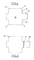
- the cutting template support device is constituted by a panel obtained from a suitably-shaped metal sheet, as shown as an example in fig. 5 .
- the sheet is cut according to the required perimeter, for example by laser machines, and then folded in such a way as to form a type of drawer.
- the drawer panel therefore presents raised rims along the respective sides; the longitudinal rims have an edge folded towards the centre of the panel, in order to form a type of guide for being slid onto the press.
- the panel also has a grip handle fixed on a corresponding transversal rim, for example by means of welding.
- the cutting template is fixed on the outer face of the support panel.
- the abovementioned cutting template support devices have various inconveniences that make its use expensive and unpractical.
- the support devices of the known type have a relatively high price, due primarily to the material from which they are made and the time and work processes required to manufacture them. It should be remembered that such support devices represent a consumable material for the machine as they must be replaced with a certain frequency, due primarily to the wear to which they are subject, and therefore in time related costs can reach a somewhat high overall value.
- the template holder devices of the known type are also awkward to use and can be dangerous for those operating them as they require manual handling in order to be introduced into the machine.
- the corners of the abovementioned longitudinal rims represent a potential hazard.
- a folded metal support disclosing the features of the preamble of claim 1 is described in GB-A-332 073 .
- the aim of the present invention is to resolve the abovementioned drawbacks by devising a support device for cutting templates that makes it possible to considerably reduce production costs.
- a further aim of the present invention is to provide a support device for cutting templates that is easy to use and safe for the operator.
- a further aim of the invention is that of providing a support device that is of simple conception, certainly reliable function and versatile in use.
- 1 refers to the support device for cutting templates, destined to be applied in a machine for cutting tubular-shaped textile products.
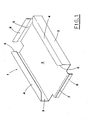
- the cutting template support device is constituted by a panel 2 obtained from a sheet of metal 10 such as stainless steel, suitably shaped according to the outline shown in fig.4 ; the metal sheet 10 is subsequently folded in such a way as to form a sort of drawer.
- the panel 2 has a substantially rectangular shape and along the longitudinal sides has raised rims 3; the longitudinal rims 3 have an edge 4 folded towards the centre of the panel 2, in such a way as to serve as a guide for sliding it onto the press.
- edges 4 of the longitudinal rims 3 have respective bevels 5 at the respective ends.
- the bevels 5 cut the outer corners of the edges 4 at an angle of 45°.
- the panel 2 presents further rims 6, 7 folded perpendicularly to the plane of the same panel 2.
- the front rim 6 is raised in the same direction as the longitudinal rims 3, in other words upwards when in an operative set-up on the press, and is destined to act as a handle of the support device.
- the frontal rim 6 usefully presents a crushed fold stretch 8, obtained by folding a marginal portion on to the inner face of the same rim 6.
- the rear rim 7 is folded downwards, in other words from the opposite side of the panel 2 to the rims 3 and 6.
- the rear rim 7 in turn presents a stretch of crushed fold 9, obtained by a marginal portion on to the outer face of the same rim 7.
- the support device for cutting templates achieves the purpose of creating a considerable reduction in production costs, in particular thanks to considerable material savings and an optimisation of the work processes required.
- the creation of the bevels 5 also has the advantage of considerably reducing the time required for the sheet 10 cutting operation, as the cutting organs, such as lasers, have to cover a shorter perimetral length than that of conventional template holders.
- the bevels 5 also have the purpose of eliminating a cutting part from the device's grip area by the operator, so as to reduce the risk of cuts and the like. In addition to reducing production costs and improving the template holder device's functionality, it also contributes to producing the grip handle in a single piece with the panel 2, by the folding of a relative portion 16 of the metal sheet 10 (see again fig. 4 ).
- the welding of the grip handle also entails the overlapping of the two parts to be joined, which determines further greater consumption of material than the solution in object, in which the handle is produced in a single piece with panel 2.
- the dotted area 17 represents the overlapping portion of the two parts to be welded for the production of the grip handle in conventional template holders and therefore the relative greater consumption of materials.
Landscapes
- Life Sciences & Earth Sciences (AREA)
- Forests & Forestry (AREA)
- Engineering & Computer Science (AREA)
- Mechanical Engineering (AREA)
- Treatment Of Fiber Materials (AREA)
- Sawing (AREA)
- Sampling And Sample Adjustment (AREA)
- Control And Other Processes For Unpacking Of Materials (AREA)
- Perforating, Stamping-Out Or Severing By Means Other Than Cutting (AREA)
- Knives (AREA)
- Accessories And Tools For Shearing Machines (AREA)
- Threshing Machine Elements (AREA)
- Mechanical Treatment Of Semiconductor (AREA)
Claims (9)
- Eine Hilfsvorrichtung für eine Schneidschablone der Art mit einer wesentlich rechteckigen Tafel (2), die durch das Abkanten eines Blechs(10) erhalten ist, das gemäß einem festgelegten Profil flach ausgedehnt ist und das entlang die Längsseiten dazugehörige aufgebogene Umrandungen (3) aufweist, die mit einem an die Innenseite der besagten Tafel (2) gerichteten Rand (4) ausgestattet sind, die fähig sind, als Führung zum Gleiten in eine Schneidemaschine zu wirken, dadurch gekennzeichnet, dass dazugehörige Abschrägungen, die fähig sind, den Umfang des besagten Profils des Blechs (10) zu reduzieren, in dem besagten Blech (10) bei den Außenkanten von gegenüberliegenden Portionen (13) verwirklicht sind, die die besagten Längsumrandungen (3) bilden, wobei der Rand (4) der auf die Innenseite der Tafel (2) aufgebogenen Längsumrandungen (3) bei den entgegengesetzten Enden an den Kanten die besagten Abschrägungen (5) aufweist.
- Vorrichtung nach Anspruch 1, dadurch gekennzeichnet, dass die besagte Tafel (2) einen Vorrand (6) aufweist, die durch das Abkanten in einem Einzelstück von derselben Tafel (2) gemacht ist und die fähig ist, als Griff der Hilfsvorrichtung zu wirken.
- Vorrichtung nach Anspruch 2, dadurch gekennzeichnet, dass der Vorrand (6) in dieselbe Richtung der besagten Längsumrandungen (3) nach oben in Gebrauchskonfiguration in der besagten Schneidemaschine erhöht ist.
- Vorrichtung nach Anspruch 2, dadurch gekennzeichnet, dass die besagte Vorrand (6) eine zerquetschte Faltestrecke (8) hat, die durch Umlegung einer Randportion über der Innerfläche desselben Randes (6) erhalten ist.
- Vorrichtung nach Anspruch 1, dadurch gekennzeichnet, dass die besagten Abschrägungen (5) gemäß einem 45°-Winkel die Außerkanten des besagten Randes (4) der besagten Längsumrandungen (3) schneiden.
- Vorrichtung nach Anspruch 1, dadurch gekennzeichnet, dass die besagte Tafel (2) einen Rückrand (7) aufweist, der auf der gegenüberliegenden Seite in Bezug auf der besagten Längsumrandungen (3) umgelegt ist.
- Vorrichtung nach Anspruch 6, dadurch gekennzeichnet, dass der besagte Rückrand (7) eine zerquetschte Faltestrecke (9) aufweist, die durch Umlegung einer Randportion über der Außerfläche desselben Randes (7) erhalten ist.
- Vorrichtung nach Anspruch 2, dadurch gekennzeichnet, dass die besagte Längsumrandungen (3) und die besagte Querrand (6) sich entlang der ganzen Länge der entsprechenden Seiten der besagten Tafel (2) nicht erstrecken, da die Winkelzonen derselben Tafel (2) von der besagten Umrandungen (3, 6) nicht betroffen sind.
- Vorrichtung nach Anspruch 8, dadurch gekennzeichnet, dass die besagten Winkelzonen derselben Tafel (2) abgetragen sind.
Priority Applications (1)
| Application Number | Priority Date | Filing Date | Title |
|---|---|---|---|
| EP07123354A EP1905557B1 (de) | 2002-11-14 | 2003-10-08 | Aufnahme für eine Schneidschablone |
Applications Claiming Priority (3)
| Application Number | Priority Date | Filing Date | Title |
|---|---|---|---|
| ITBO20020718 | 2002-11-14 | ||
| IT000718A ITBO20020718A1 (it) | 2002-11-14 | 2002-11-14 | Dispositivo di supporto per sagome di taglio. |
| PCT/IT2003/000603 WO2004043660A1 (en) | 2002-11-14 | 2003-10-08 | Support device for cutting templates |
Related Child Applications (1)
| Application Number | Title | Priority Date | Filing Date |
|---|---|---|---|
| EP07123354A Division EP1905557B1 (de) | 2002-11-14 | 2003-10-08 | Aufnahme für eine Schneidschablone |
Publications (2)
| Publication Number | Publication Date |
|---|---|
| EP1590137A1 EP1590137A1 (de) | 2005-11-02 |
| EP1590137B1 true EP1590137B1 (de) | 2008-07-16 |
Family
ID=32310128
Family Applications (2)
| Application Number | Title | Priority Date | Filing Date |
|---|---|---|---|
| EP07123354A Expired - Lifetime EP1905557B1 (de) | 2002-11-14 | 2003-10-08 | Aufnahme für eine Schneidschablone |
| EP03772636A Expired - Lifetime EP1590137B1 (de) | 2002-11-14 | 2003-10-08 | Hilfsvorrichtung für eine schneidschablone |
Family Applications Before (1)
| Application Number | Title | Priority Date | Filing Date |
|---|---|---|---|
| EP07123354A Expired - Lifetime EP1905557B1 (de) | 2002-11-14 | 2003-10-08 | Aufnahme für eine Schneidschablone |
Country Status (7)
| Country | Link |
|---|---|
| US (1) | US7533554B2 (de) |
| EP (2) | EP1905557B1 (de) |
| AT (2) | ATE554895T1 (de) |
| DE (1) | DE60322268D1 (de) |
| ES (1) | ES2310248T3 (de) |
| IT (1) | ITBO20020718A1 (de) |
| WO (1) | WO2004043660A1 (de) |
Families Citing this family (2)
| Publication number | Priority date | Publication date | Assignee | Title |
|---|---|---|---|---|
| US8708304B2 (en) * | 2007-11-27 | 2014-04-29 | Bsh Home Appliances Corporation | Appliance base for an appliance |
| US7806024B1 (en) * | 2008-02-20 | 2010-10-05 | Forest Hill Manufacturing, Llc | Method for making shovel |
Family Cites Families (10)
| Publication number | Priority date | Publication date | Assignee | Title |
|---|---|---|---|---|
| US1467787A (en) * | 1921-05-25 | 1923-09-11 | Worthy D Gemmill | Frame and method of making it |
| GB332073A (en) * | 1929-07-27 | 1930-07-17 | T H Prosser And Sons Ltd | Improvements relating to sliding bins of kitchen cabinets and the like |
| GB620552A (en) * | 1947-01-22 | 1949-03-25 | Weldall & Assembly Ltd | Improvements in or relating to drawers |
| CH372546A (fr) * | 1962-01-11 | 1963-10-15 | Bobst Fils Sa J | Procédé de fixation auxiliaire de l'outil d'une presse à platines en position de travail contre le sommier supérieur et dispositif pour la mise en oeuvre de ce procédé |
| DE3403323A1 (de) * | 1984-01-31 | 1985-08-01 | Edgar 8120 Weilheim Erdmann | Fotografische schneidvorrichtung |
| JPH0195818A (ja) * | 1987-10-07 | 1989-04-13 | Matsushita Electric Works Ltd | 鈑金製箱の加工方法 |
| GB2286960A (en) * | 1994-02-25 | 1995-09-06 | Ub Office Systems Co Ltd | Flat pack assembly-type cabinet |
| US6478391B1 (en) * | 1998-06-17 | 2002-11-12 | Sandusky Cabinets, Inc. | Cabinet |
| DE19855127B4 (de) * | 1998-11-30 | 2006-09-21 | Man Roland Druckmaschinen Ag | Abdeckung |
| DE19911499C2 (de) * | 1999-03-16 | 2002-06-27 | Koehler Gmbh | Backblech o. dgl. |
-
2002
- 2002-11-14 IT IT000718A patent/ITBO20020718A1/it unknown
-
2003
- 2003-10-08 US US10/489,981 patent/US7533554B2/en not_active Expired - Fee Related
- 2003-10-08 AT AT07123354T patent/ATE554895T1/de active
- 2003-10-08 DE DE60322268T patent/DE60322268D1/de not_active Expired - Fee Related
- 2003-10-08 ES ES03772636T patent/ES2310248T3/es not_active Expired - Lifetime
- 2003-10-08 WO PCT/IT2003/000603 patent/WO2004043660A1/en not_active Ceased
- 2003-10-08 EP EP07123354A patent/EP1905557B1/de not_active Expired - Lifetime
- 2003-10-08 EP EP03772636A patent/EP1590137B1/de not_active Expired - Lifetime
- 2003-10-08 AT AT03772636T patent/ATE401177T1/de not_active IP Right Cessation
Also Published As
| Publication number | Publication date |
|---|---|
| ATE401177T1 (de) | 2008-08-15 |
| US7533554B2 (en) | 2009-05-19 |
| ITBO20020718A1 (it) | 2004-05-15 |
| DE60322268D1 (de) | 2008-08-28 |
| EP1590137A1 (de) | 2005-11-02 |
| EP1905557B1 (de) | 2012-04-25 |
| WO2004043660A1 (en) | 2004-05-27 |
| EP1905557A3 (de) | 2009-07-15 |
| EP1905557A2 (de) | 2008-04-02 |
| ATE554895T1 (de) | 2012-05-15 |
| ES2310248T3 (es) | 2009-01-01 |
| US20050230595A1 (en) | 2005-10-20 |
Similar Documents
| Publication | Publication Date | Title |
|---|---|---|
| US20170274547A1 (en) | Cutting device for cutting relatively rigid web materials such as paper, cardboard, plastic materials or composites | |
| EP1905557B1 (de) | Aufnahme für eine Schneidschablone | |
| DE69518408D1 (de) | Multidirektionales schneidewerkzeug für schneidpressen | |
| CA2118568A1 (en) | Tool grinding machine | |
| US2381955A (en) | Envelope machine | |
| US3079846A (en) | Method and apparatus for scoring and slotting carton blanks | |
| US4036269A (en) | Automatic shaping device with a pre-cutting assembly | |
| DE60001289D1 (de) | Werkzeug zum Biegen und Abkanten für eine Biegepresse und mit diesem Werkzeug ausgerüstete Biegepresse | |
| KR101544980B1 (ko) | 모서리 라운드 펀칭기 | |
| EP1063041A3 (de) | Werkzeugsystem für spannenden Metallbearbeitung von plattenförmigen Werkstücken | |
| KR840006156A (ko) | 조합된 전단 및 펀치 프레스 | |
| US4938105A (en) | Method of manufacturing a one-sided or two-sided punching knife for non-metallic materials | |
| CN212653008U (zh) | 辊轧折弯分切一体机 | |
| DE3063261D1 (en) | Cutting tool for cutting out a cut of sheet metal | |
| CN211362376U (zh) | 边料切除治具 | |
| US20060081103A1 (en) | Grid cutting device | |
| CN214866443U (zh) | 一种具有物料快速定位功能的数控冲床 | |
| CN219504950U (zh) | 一种高精度模切机的自动感应机构 | |
| CN111497328A (zh) | 一种纸箱生产用冲压平台 | |
| JPH02108420A (ja) | 折曲げ型 | |
| CN218798350U (zh) | 一种不锈钢折弯装置 | |
| CN117206410B (zh) | 一种用于加工托曳臂小头的冲压剪缝工艺 | |
| CN212917196U (zh) | 合金圆锯片多齿冲压手动换位装夹模具 | |
| US3509756A (en) | Portable flanging tool | |
| KR200227181Y1 (ko) | 후강판의가스절단설자동제거장치 |
Legal Events
| Date | Code | Title | Description |
|---|---|---|---|
| PUAI | Public reference made under article 153(3) epc to a published international application that has entered the european phase |
Free format text: ORIGINAL CODE: 0009012 |
|
| 17P | Request for examination filed |
Effective date: 20040416 |
|
| AK | Designated contracting states |
Kind code of ref document: A1 Designated state(s): AT BE BG CH CY CZ DE DK EE ES FI FR GB GR HU IE IT LI LU MC NL PT RO SE SI SK TR |
|
| AX | Request for extension of the european patent |
Extension state: AL LT LV MK |
|
| DAX | Request for extension of the european patent (deleted) | ||
| 17Q | First examination report despatched |
Effective date: 20070420 |
|
| RAP1 | Party data changed (applicant data changed or rights of an application transferred) |
Owner name: CORTESE S.P.A. |
|
| RIN1 | Information on inventor provided before grant (corrected) |
Inventor name: CORTESE, CARMELO ANGELO |
|
| GRAP | Despatch of communication of intention to grant a patent |
Free format text: ORIGINAL CODE: EPIDOSNIGR1 |
|
| GRAC | Information related to communication of intention to grant a patent modified |
Free format text: ORIGINAL CODE: EPIDOSCIGR1 |
|
| GRAS | Grant fee paid |
Free format text: ORIGINAL CODE: EPIDOSNIGR3 |
|
| GRAA | (expected) grant |
Free format text: ORIGINAL CODE: 0009210 |
|
| AK | Designated contracting states |
Kind code of ref document: B1 Designated state(s): AT BE BG CH CY CZ DE DK EE ES FI FR GB GR HU IE IT LI LU MC NL PT RO SE SI SK TR |
|
| REG | Reference to a national code |
Ref country code: GB Ref legal event code: FG4D |
|
| REG | Reference to a national code |
Ref country code: CH Ref legal event code: EP |
|
| REF | Corresponds to: |
Ref document number: 60322268 Country of ref document: DE Date of ref document: 20080828 Kind code of ref document: P |
|
| REG | Reference to a national code |
Ref country code: IE Ref legal event code: FG4D |
|
| REG | Reference to a national code |
Ref country code: RO Ref legal event code: EPE |
|
| REG | Reference to a national code |
Ref country code: ES Ref legal event code: FG2A Ref document number: 2310248 Country of ref document: ES Kind code of ref document: T3 |
|
| NLV1 | Nl: lapsed or annulled due to failure to fulfill the requirements of art. 29p and 29m of the patents act | ||
| PG25 | Lapsed in a contracting state [announced via postgrant information from national office to epo] |
Ref country code: PT Free format text: LAPSE BECAUSE OF FAILURE TO SUBMIT A TRANSLATION OF THE DESCRIPTION OR TO PAY THE FEE WITHIN THE PRESCRIBED TIME-LIMIT Effective date: 20081216 Ref country code: NL Free format text: LAPSE BECAUSE OF FAILURE TO SUBMIT A TRANSLATION OF THE DESCRIPTION OR TO PAY THE FEE WITHIN THE PRESCRIBED TIME-LIMIT Effective date: 20080716 |
|
| PG25 | Lapsed in a contracting state [announced via postgrant information from national office to epo] |
Ref country code: SI Free format text: LAPSE BECAUSE OF FAILURE TO SUBMIT A TRANSLATION OF THE DESCRIPTION OR TO PAY THE FEE WITHIN THE PRESCRIBED TIME-LIMIT Effective date: 20080716 Ref country code: BG Free format text: LAPSE BECAUSE OF FAILURE TO SUBMIT A TRANSLATION OF THE DESCRIPTION OR TO PAY THE FEE WITHIN THE PRESCRIBED TIME-LIMIT Effective date: 20081016 Ref country code: AT Free format text: LAPSE BECAUSE OF FAILURE TO SUBMIT A TRANSLATION OF THE DESCRIPTION OR TO PAY THE FEE WITHIN THE PRESCRIBED TIME-LIMIT Effective date: 20080716 Ref country code: FI Free format text: LAPSE BECAUSE OF FAILURE TO SUBMIT A TRANSLATION OF THE DESCRIPTION OR TO PAY THE FEE WITHIN THE PRESCRIBED TIME-LIMIT Effective date: 20080716 |
|
| PGFP | Annual fee paid to national office [announced via postgrant information from national office to epo] |
Ref country code: ES Payment date: 20081022 Year of fee payment: 6 Ref country code: RO Payment date: 20081008 Year of fee payment: 6 |
|
| PG25 | Lapsed in a contracting state [announced via postgrant information from national office to epo] |
Ref country code: BE Free format text: LAPSE BECAUSE OF FAILURE TO SUBMIT A TRANSLATION OF THE DESCRIPTION OR TO PAY THE FEE WITHIN THE PRESCRIBED TIME-LIMIT Effective date: 20080716 |
|
| PG25 | Lapsed in a contracting state [announced via postgrant information from national office to epo] |
Ref country code: EE Free format text: LAPSE BECAUSE OF FAILURE TO SUBMIT A TRANSLATION OF THE DESCRIPTION OR TO PAY THE FEE WITHIN THE PRESCRIBED TIME-LIMIT Effective date: 20080716 Ref country code: DK Free format text: LAPSE BECAUSE OF FAILURE TO SUBMIT A TRANSLATION OF THE DESCRIPTION OR TO PAY THE FEE WITHIN THE PRESCRIBED TIME-LIMIT Effective date: 20080716 |
|
| PLBE | No opposition filed within time limit |
Free format text: ORIGINAL CODE: 0009261 |
|
| STAA | Information on the status of an ep patent application or granted ep patent |
Free format text: STATUS: NO OPPOSITION FILED WITHIN TIME LIMIT |
|
| PG25 | Lapsed in a contracting state [announced via postgrant information from national office to epo] |
Ref country code: MC Free format text: LAPSE BECAUSE OF NON-PAYMENT OF DUE FEES Effective date: 20081031 Ref country code: SK Free format text: LAPSE BECAUSE OF FAILURE TO SUBMIT A TRANSLATION OF THE DESCRIPTION OR TO PAY THE FEE WITHIN THE PRESCRIBED TIME-LIMIT Effective date: 20080716 Ref country code: CZ Free format text: LAPSE BECAUSE OF FAILURE TO SUBMIT A TRANSLATION OF THE DESCRIPTION OR TO PAY THE FEE WITHIN THE PRESCRIBED TIME-LIMIT Effective date: 20080716 |
|
| REG | Reference to a national code |
Ref country code: CH Ref legal event code: PL |
|
| 26N | No opposition filed |
Effective date: 20090417 |
|
| GBPC | Gb: european patent ceased through non-payment of renewal fee |
Effective date: 20081016 |
|
| REG | Reference to a national code |
Ref country code: IE Ref legal event code: MM4A |
|
| REG | Reference to a national code |
Ref country code: FR Ref legal event code: ST Effective date: 20090630 |
|
| PG25 | Lapsed in a contracting state [announced via postgrant information from national office to epo] |
Ref country code: DE Free format text: LAPSE BECAUSE OF NON-PAYMENT OF DUE FEES Effective date: 20090501 |
|
| PG25 | Lapsed in a contracting state [announced via postgrant information from national office to epo] |
Ref country code: CH Free format text: LAPSE BECAUSE OF NON-PAYMENT OF DUE FEES Effective date: 20081031 Ref country code: LI Free format text: LAPSE BECAUSE OF NON-PAYMENT OF DUE FEES Effective date: 20081031 Ref country code: IE Free format text: LAPSE BECAUSE OF NON-PAYMENT OF DUE FEES Effective date: 20081008 Ref country code: FR Free format text: LAPSE BECAUSE OF NON-PAYMENT OF DUE FEES Effective date: 20081031 |
|
| PG25 | Lapsed in a contracting state [announced via postgrant information from national office to epo] |
Ref country code: GB Free format text: LAPSE BECAUSE OF NON-PAYMENT OF DUE FEES Effective date: 20081016 |
|
| PG25 | Lapsed in a contracting state [announced via postgrant information from national office to epo] |
Ref country code: SE Free format text: LAPSE BECAUSE OF FAILURE TO SUBMIT A TRANSLATION OF THE DESCRIPTION OR TO PAY THE FEE WITHIN THE PRESCRIBED TIME-LIMIT Effective date: 20081016 |
|
| PG25 | Lapsed in a contracting state [announced via postgrant information from national office to epo] |
Ref country code: HU Free format text: LAPSE BECAUSE OF FAILURE TO SUBMIT A TRANSLATION OF THE DESCRIPTION OR TO PAY THE FEE WITHIN THE PRESCRIBED TIME-LIMIT Effective date: 20090117 Ref country code: LU Free format text: LAPSE BECAUSE OF NON-PAYMENT OF DUE FEES Effective date: 20081008 Ref country code: CY Free format text: LAPSE BECAUSE OF FAILURE TO SUBMIT A TRANSLATION OF THE DESCRIPTION OR TO PAY THE FEE WITHIN THE PRESCRIBED TIME-LIMIT Effective date: 20080716 |
|
| PG25 | Lapsed in a contracting state [announced via postgrant information from national office to epo] |
Ref country code: TR Free format text: LAPSE BECAUSE OF FAILURE TO SUBMIT A TRANSLATION OF THE DESCRIPTION OR TO PAY THE FEE WITHIN THE PRESCRIBED TIME-LIMIT Effective date: 20080716 |
|
| PG25 | Lapsed in a contracting state [announced via postgrant information from national office to epo] |
Ref country code: GR Free format text: LAPSE BECAUSE OF FAILURE TO SUBMIT A TRANSLATION OF THE DESCRIPTION OR TO PAY THE FEE WITHIN THE PRESCRIBED TIME-LIMIT Effective date: 20081017 |
|
| PG25 | Lapsed in a contracting state [announced via postgrant information from national office to epo] |
Ref country code: RO Free format text: LAPSE BECAUSE OF NON-PAYMENT OF DUE FEES Effective date: 20091008 |
|
| REG | Reference to a national code |
Ref country code: ES Ref legal event code: FD2A Effective date: 20110331 |
|
| PG25 | Lapsed in a contracting state [announced via postgrant information from national office to epo] |
Ref country code: ES Free format text: LAPSE BECAUSE OF NON-PAYMENT OF DUE FEES Effective date: 20110321 |
|
| PG25 | Lapsed in a contracting state [announced via postgrant information from national office to epo] |
Ref country code: ES Free format text: LAPSE BECAUSE OF NON-PAYMENT OF DUE FEES Effective date: 20091009 |
|
| PGFP | Annual fee paid to national office [announced via postgrant information from national office to epo] |
Ref country code: IT Payment date: 20151027 Year of fee payment: 13 |
|
| PG25 | Lapsed in a contracting state [announced via postgrant information from national office to epo] |
Ref country code: IT Free format text: LAPSE BECAUSE OF NON-PAYMENT OF DUE FEES Effective date: 20161008 |