EP1587645B1 - Anlage zum selektiven speichern und wiedereinbringen von teilen in einer industriemontagelinie - Google Patents
Anlage zum selektiven speichern und wiedereinbringen von teilen in einer industriemontagelinie Download PDFInfo
- Publication number
- EP1587645B1 EP1587645B1 EP02764437A EP02764437A EP1587645B1 EP 1587645 B1 EP1587645 B1 EP 1587645B1 EP 02764437 A EP02764437 A EP 02764437A EP 02764437 A EP02764437 A EP 02764437A EP 1587645 B1 EP1587645 B1 EP 1587645B1
- Authority
- EP
- European Patent Office
- Prior art keywords
- conveyor
- container
- parts
- containers
- assembly line
- Prior art date
- Legal status (The legal status is an assumption and is not a legal conclusion. Google has not performed a legal analysis and makes no representation as to the accuracy of the status listed.)
- Expired - Lifetime
Links
Images


Classifications
-
- B—PERFORMING OPERATIONS; TRANSPORTING
- B23—MACHINE TOOLS; METAL-WORKING NOT OTHERWISE PROVIDED FOR
- B23P—METAL-WORKING NOT OTHERWISE PROVIDED FOR; COMBINED OPERATIONS; UNIVERSAL MACHINE TOOLS
- B23P19/00—Machines for simply fitting together or separating metal parts or objects, or metal and non-metal parts, whether or not involving some deformation; Tools or devices therefor so far as not provided for in other classes
- B23P19/001—Article feeders for assembling machines
-
- B—PERFORMING OPERATIONS; TRANSPORTING
- B23—MACHINE TOOLS; METAL-WORKING NOT OTHERWISE PROVIDED FOR
- B23P—METAL-WORKING NOT OTHERWISE PROVIDED FOR; COMBINED OPERATIONS; UNIVERSAL MACHINE TOOLS
- B23P21/00—Machines for assembling a multiplicity of different parts to compose units, with or without preceding or subsequent working of such parts, e.g. with program control
- B23P21/004—Machines for assembling a multiplicity of different parts to compose units, with or without preceding or subsequent working of such parts, e.g. with program control the units passing two or more work-stations whilst being composed
-
- B—PERFORMING OPERATIONS; TRANSPORTING
- B23—MACHINE TOOLS; METAL-WORKING NOT OTHERWISE PROVIDED FOR
- B23Q—DETAILS, COMPONENTS, OR ACCESSORIES FOR MACHINE TOOLS, e.g. ARRANGEMENTS FOR COPYING OR CONTROLLING; MACHINE TOOLS IN GENERAL CHARACTERISED BY THE CONSTRUCTION OF PARTICULAR DETAILS OR COMPONENTS; COMBINATIONS OR ASSOCIATIONS OF METAL-WORKING MACHINES, NOT DIRECTED TO A PARTICULAR RESULT
- B23Q7/00—Arrangements for handling work specially combined with or arranged in, or specially adapted for use in connection with, machine tools, e.g. for conveying, loading, positioning, discharging, sorting
- B23Q7/04—Arrangements for handling work specially combined with or arranged in, or specially adapted for use in connection with, machine tools, e.g. for conveying, loading, positioning, discharging, sorting by means of grippers
-
- B—PERFORMING OPERATIONS; TRANSPORTING
- B23—MACHINE TOOLS; METAL-WORKING NOT OTHERWISE PROVIDED FOR
- B23Q—DETAILS, COMPONENTS, OR ACCESSORIES FOR MACHINE TOOLS, e.g. ARRANGEMENTS FOR COPYING OR CONTROLLING; MACHINE TOOLS IN GENERAL CHARACTERISED BY THE CONSTRUCTION OF PARTICULAR DETAILS OR COMPONENTS; COMBINATIONS OR ASSOCIATIONS OF METAL-WORKING MACHINES, NOT DIRECTED TO A PARTICULAR RESULT
- B23Q7/00—Arrangements for handling work specially combined with or arranged in, or specially adapted for use in connection with, machine tools, e.g. for conveying, loading, positioning, discharging, sorting
- B23Q7/10—Arrangements for handling work specially combined with or arranged in, or specially adapted for use in connection with, machine tools, e.g. for conveying, loading, positioning, discharging, sorting by means of magazines
-
- B—PERFORMING OPERATIONS; TRANSPORTING
- B23—MACHINE TOOLS; METAL-WORKING NOT OTHERWISE PROVIDED FOR
- B23Q—DETAILS, COMPONENTS, OR ACCESSORIES FOR MACHINE TOOLS, e.g. ARRANGEMENTS FOR COPYING OR CONTROLLING; MACHINE TOOLS IN GENERAL CHARACTERISED BY THE CONSTRUCTION OF PARTICULAR DETAILS OR COMPONENTS; COMBINATIONS OR ASSOCIATIONS OF METAL-WORKING MACHINES, NOT DIRECTED TO A PARTICULAR RESULT
- B23Q7/00—Arrangements for handling work specially combined with or arranged in, or specially adapted for use in connection with, machine tools, e.g. for conveying, loading, positioning, discharging, sorting
- B23Q7/14—Arrangements for handling work specially combined with or arranged in, or specially adapted for use in connection with, machine tools, e.g. for conveying, loading, positioning, discharging, sorting co-ordinated in production lines
- B23Q7/1426—Arrangements for handling work specially combined with or arranged in, or specially adapted for use in connection with, machine tools, e.g. for conveying, loading, positioning, discharging, sorting co-ordinated in production lines with work holders not rigidly fixed to the transport devices
-
- B—PERFORMING OPERATIONS; TRANSPORTING
- B65—CONVEYING; PACKING; STORING; HANDLING THIN OR FILAMENTARY MATERIAL
- B65G—TRANSPORT OR STORAGE DEVICES, e.g. CONVEYORS FOR LOADING OR TIPPING, SHOP CONVEYOR SYSTEMS OR PNEUMATIC TUBE CONVEYORS
- B65G65/00—Loading or unloading
Definitions
- the present invention relates generally to a system for selectively and temporarily storing parts from an industrial assembly line and then subsequently reintroducing the parts into the assembly line.
- Modem industrial assembly lines typically contain a number of sequential stations along the assembly line. A work operation, assembly, machining operation or the like is typically performed at each station along the assembly line.
- one or more stations may be temporarily inoperable. For example, it may be necessary to replace the tooling at a particular station and during that changeover, the station is inoperable. Likewise, a malfunction or breakage at the assembly station may render the station inoperable for a period of time.
- a primary disadvantage of this previously known method for maintaining the flow of parts along an industrial assembly line is that the manual temporary storage of parts and the subsequent manual reintroduction of those parts into the assembly line is necessarily labor intensive and, therefore, expensive.
- Closest prior art JP 2001249711 discloses a system comprising a first conveyor and a second conveyor, each conveyor having a first end and a second end a robot manipulator positioned adjacent the assembly line and adjacent said first ends of said conveyors, said robot manipulator being configured to selectively engage and release parts, and a plurality of containers, each container adapted to receive a plurality of the parts in predetermined positions within the container.
- JP2001249711 describes a distribution buffering system for maintaining or increasing efficiency of a production line.
- the system comprises two storage buffers, each having storage containers in which parts may be temporarily stored, a robot for moving parts and a sensor for monitoring the rate at which parts are moving along the production line.
- the robot Upon sensing a number of parts moving along the production line, relative to time, in excess of a pre-determined threshold the robot is activated to remove one or more of the parts from the production line and place each part in a container on a storage buffer. If the sensor senses a number of parts moving along the production line, relative to time, below a predetermined threshold the robot moves one or more parts from the storage buffers onto the production line.
- this system is restricted in that the containers are fixed to their relative storage buffer and therefore storage of the parts is restricted.
- the present invention provides an automatic system that overcomes all of the above-mentioned disadvantages of the previously known methods.
- a system for temporarily storing and subsequently reintroducing parts into an industrial assembly line comprising a first conveyor and a second conveyor, each conveyor having a first end and a second end, a robot manipulator positioned adjacent the assembly line and adjacent said first ends of said conveyors, said robot manipulator being configured to selectively engage and release parts and also to move empty containers, a plurality of containers, each container adapted to receive a plurality of the parts in predetermined positions within the container, a first and second alignment rail, said first alignment rail positioned adjacent the first end of said first conveyor and said second alignment rail positioned adjacent the first end of said second conveyor, a first actuator movable between an extended position in which said actuator engages one container at said first end of said first conveyor and moves said one container against said first alignment rail, and a retracted position, a second actuator movable between an extended position in which said actuator engages one container at said first end of said second conveyor and moves said one container against said second alignment rail, and a retracted position, a controller which
- the present invention comprises a first and second conveyor wherein each conveyor has both a first end and a second end.
- a robot manipulator is positioned adjacent to the assembly line and also adjacent the first ends of the conveyors. This robot manipulator, furthermore, is configured to selectively engage and release parts of the type conveyed by the assembly line.
- the system of the present invention further comprises a plurality of containers wherein each container is adapted to receive a plurality of parts in predetermined positions within the container.
- the containers are stackable to a predetermined height, e.g. five containers.
- an alignment rail is provided along one corner at the first end of each conveyor.
- An actuator is then mounted cross corner from the container and movable between an extended and a retracted position. In its extended position, the actuator engages and moves the container against the alignment rail thus accurately positioning the container. Conversely, in its retracted position, the actuator is moved away from the container and allows the containers to be moved by the conveyors.
- a controller selectively controls both the activation and direction of movement of both conveyors, as well as the operation of the robotic arm.
- the controller also controls the activation of the actuators.
- the system is positioned upstream from a workstation along the assembly line which, in turn, is normally supplied parts from workstations upstream from the system. Assuming that the assembly line provides an uninterrupted flow of parts to the workstation and that the workstation is operable, the system of the present invention stands idle.
- empty containers are conveyed to the first end of the second conveyor.
- the robotic arm then moves an empty container from the second conveyor and onto the first end of the first conveyor.
- the controller then actuates the actuator to position the empty container at a predetermined position at the first end of the first conveyor whereupon the robotic manipulator fills the container with parts supplied on the assembly line to the temporarily inoperable workstation.
- the robotic actuator fills one container, it positions an empty container from the second conveyor on top of the filled container on the first conveyor and then fills that container. That process is repeated until the filled containers at the first end of the first conveyor are of a predetermined height, for example a stack of five filled containers.
- the controller actuates the first conveyor to move the filled containers to the second end of the first conveyor and simultaneously activates the second conveyor to move a new stack of empty containers to the first end of the second conveyor whereupon the above process is repeated.
- the stack of filled containers is removed from the second end of the first conveyor by conventional means, such as a forklift truck, while, similarly, a stack of empty containers is positioned on the second end of the second conveyor.
- the above process is repeated until the normal flow of parts through the workstation is reestablished. However, in the event of an interruption in the supply of parts to the workstation, the above process is simply reversed. More specifically, the robot manipulator removes parts from filled cartons at the first end of the first conveyor and reintroduces these parts into the assembly line. Once a container is empty, the robot manipulator moves the empty container from the first end of the first conveyor and to the first end of the second conveyor. A stack of filled containers is also positioned at the second end of the first conveyor.
- the controller actuates the conveyors to move a fresh supply of new filled containers from the second end and to the first end of the first conveyor and, simultaneously, to move the stack of empty containers from the first end of the second conveyor and to the second end of the second conveyor. The above process is then repeated.
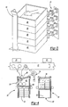
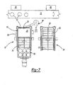
- FIG. 1 a preferred embodiment of the system 10 of the present invention is shown for use with an industrial assembly line 12 (illustrated only diagrammatically).
- the industrial assembly line 12 furthermore, moves a plurality of parts 14 in the direction of arrow 16 to sequential workstations 18 and 20 (illustrated only diagrammatically) along the assembly line 12.
- the system 10 comprises a first conveyor 22 and a second conveyor 24 which are positioned side by side.
- Each conveyor 22 and 24 includes a first end 26 and 28 and a second end 30 and 32, respectively.
- a robot manipulator 34 is positioned adjacent the first ends 26 and 28 of the conveyors 22 and 24 and also adjacent the assembly line 12.
- the robot manipulator 34 furthermore, is configured to selectively engage, move and thereafter release the parts 14 of the type conveyed by the assembly line 12.
- the system 10 includes a plurality of containers 40 each of which are adapted to receive a predetermined number of parts, e.g. six parts, at a predetermined position within the container 40. Furthermore, the containers 40 are preferably stackable to a predetermined height, e.g. five containers tall, as best shown in FIG. 3 .
- an alignment rail 42 is positioned adjacent one corner at the first end 26 of the first conveyor 22.
- a second alignment rail 44 ( FIG. 2 only) is positioned adjacent one corner at the first end 28 of the second conveyor 24.
- a first actuator 46 is mounted to the conveyor 22 cross corner from the first alignment rail 42 while, similarly, a second actuator 48 is mounted cross corner from the second alignment rail 44 on the second conveyor 24.
- the actuators 46 and 48 operate in an identical fashion so that only a description of the actuator 46 together with its alignment rail 42 is necessary, the same description being also applicable to the actuator 48 and its alignment rail 44. More specifically, as best shown in FIG. 3 , the actuator 46 is movable between an extended position, illustrated in solid line in FIG. 3 , and a retracted position, illustrated in phantom line in FIG. 3 . In its extended position, the actuator 46 engages a container 40 positioned at the first end 26 of the first conveyor 22 and moves the container 40 against the alignment rail 42. In doing so, the actuator 46 precisely positions the container 40 relative to the conveyor 22 and thus relative to the robot manipulator 34.
- the robot manipulator 42 can accurately position the parts 14 either from the assembly line 12 and into the container 40 or, alternatively, remove the parts from the containers 40 and place them on the assembly line 12.
- the actuators 46 are pneumatic actuators.
- a controller 50 such as a PLC controller, is operatively connected to both conveyors 22 and 24 as well as the actuators 46 and 48 and the robot manipulator 34.
- the controller 50 thus controls both the actuation as well as direction of movement of the conveyors 22 and 24 as well as the activation of the actuators 46 and 48 and the movement of the robot manipulator 34.
- the controller 50 itself, however, is conventional in construction so that a further description thereof is unnecessary.
- the workstation 20 becomes temporarily inoperative so that it is desirable to temporarily store the parts 14 received from the upstream workstation 18 in the containers 40.
- a stack of empty containers is moved from the second end 32 and to the first end 28 of the second conveyor 24.
- the robot manipulator 34 is then activated by the controller 50 to lift the topmost empty container 40 from the second conveyor 24 and place it at the first end 26 of the first conveyor 22.
- the actuator 46 is then actuated to position the container 40 against its alignment rail 42 and thus accurately position the empty container 40 relative to the robot manipulator 34.
- the robot manipulator 34 then removes the parts 14 from the assembly line 12 and places the parts at predetermined positions within the empty container 40.
- a stack 60 of empty containers is also positioned at the second end 32 of the second conveyor 24.
- the robot manipulator selects the top empty container 40 from the second conveyor 24, places the empty container on top of the now filled container on the conveyor 22, and the above-identified process is repeated until all of the containers are removed from the second conveyor 24 and filled with parts on the first conveyor 22.
- the controller 50 activates the conveyors 22 and 24 to move the filled stack 58 of parts from the first end 26 of the first conveyor 22 and to the second end 30. Simultaneously, the controller 50 activates the second conveyor 24 to move the stack 60 of empty containers 40 from the second end of the second conveyor 24 and to its first end 28. The system then moves the empty containers from the second conveyor 24 onto the first conveyor 22 and fills these containers 40 in the previously described fashion. During that time, the stack 58 of the now filled containers is removed from the second end 30 of the first conveyor 22 by conventional means, such as a hi-lo truck. Likewise, a stack 60 of empty containers is positioned on the second end 32 of the second conveyor 24.
- the controller 50 then reverses the operation thus far described.
- the robot manipulator 34 removes parts from the filled containers 40 at the first end of the first conveyor 22.
- the robot manipulator 40 moves the now empty container from the first conveyor 22 and to the first end 28 of the second conveyor 24.
- the actuators 46 and 48 accurately position the containers 40, filled or empty, on the conveyors 22 and 24.
- the controller 50 activates both conveyors 22 and 24 to both move the stack 58 of filled containers 40 from the second end 30 of the first conveyor and to the first end 26 of the first conveyor and move the stack 60 of empty containers from the first end 28 of the second conveyor 24 and to its second end 32.
- the stack 60 of empty containers is then removed by conventional means, such as a hi-lo truck, from the second end 32 of the second conveyor 26 while, likewise, a stack of filled containers is positioned on the second end 30 of the first conveyor 22. This process is repeated until normal operation of the assembly line 12 resumes.
- the present invention provides an automatic system for temporarily storing and then reintroducing parts from an assembly line as workstations both upstream and downstream from the system become temporarily disabled.
Landscapes
- Engineering & Computer Science (AREA)
- Mechanical Engineering (AREA)
- Automatic Assembly (AREA)
- Container Filling Or Packaging Operations (AREA)
- Specific Conveyance Elements (AREA)
- Automobile Manufacture Line, Endless Track Vehicle, Trailer (AREA)
- Electrical Discharge Machining, Electrochemical Machining, And Combined Machining (AREA)
- Moulding By Coating Moulds (AREA)
Claims (8)
- System (10) für die vorläufige Lagerung und anschließende Wiederzuführung von Teilen (14) auf ein Fließband (12), bestehend aus:einem ersten Förderer (22) und einem zweiten Förderer (24), wobei jeder Förderer ein erstes Ende (26) (28) und ein zweites Ende (30) (32) aufweist,einem anschließend an das Fließband (12) und anschließend an die ersten Enden (26) (28) der Förderer (22) (24) angebrachten Robotermanipulator (34), der so ausgelegt ist, dass er Teile selektiv fassen und freigeben kann und auch leere Behälter (40) bewegen kann,eine Vielzahl an Behältern (40), die jeweils so eingerichtet sind, dass sie eine Vielzahl an Teilen (14) in vorgegebenen Positionen innerhalb der Behälter (40) aufnehmen können,eine erste und zweite Ausrichteschiene, wobei die erste Ausrichteschiene (42) anschließend an das erste Ende (26) des ersten Förderers (22) und die zweite Ausrichteschiene (44) anschließend an das erste Ende des zweiten Förderers (24) angebracht ist,einen ersten Aktuator (46), der zwischen einer ausgefahrenen Stellung, in der er einen Behälter (40) am ersten Ende (26) des ersten Förderers (22) fasst unddiesen Behälter gegen die erste Ausrichteschiene (42) bewegt, und einer eingezogenen Stellung bewegbar ist,einen zweiten Aktuator (48), der zwischen einer ausgefahrenen Stellung, in der er einen Behälter (40) am ersten Ende (28) des zweiten Förderers (24) fasst und diesen Behälter gegen die zweite Ausrichteschiene (44) bewegt, und einer eingezogenen Stellung bewegbar ist,einen Controller (50), der die Aktivierung und Bewegungsrichtung der Förderer (22) (24), die Aktivierung der Aktuatoren (26) (48) und den Robotermanipulator (34) so steuert, dass die Teile (14) selektiv zwischen dem Fließband (12) undden Behältern (40) auf dem ersten Förderer (22) bewegt werden können undleere Behälter selektiv zwischen dem ersten Förderer (22) und dem zweiten Förderer (24) bewegt werden können.
- System gemäß Anspruch 1, dadurch gekennzeichnet, dass der Controller (50) den Robotermanipulator (34) selektiv so steuert, dass leere Behälter (40) vom ersten Ende (26) (28) des einen Behälters (22) (24) und auf einen gefüllten Behälter am ersten Ende (26) (28) des anderen Behälters (22) (24) bewegt werden können.
- System gemäß Anspruch 1 oder 2, dadurch gekennzeichnet, dass die Ausrichteschienen (42) (44) anschließend an einer Ecke des ersten Endes (26) (28) ihrer jeweiligen Behälter (22) (24) angebracht werden, und dass die Aktuatoren (46) (48) an der ihren jeweiligen Ausrichteschienen (42) (44) schräg gegenüber liegenden Ecke angebracht werden.
- System gemäß Anspruch 3, dadurch gekennzeichnet, dass jeder Aktuator (46) (48) sich entlang einer Achse, ausgerichtet mit seiner gemeinsamen Ausrichtungsschiene (42) (44) bewegt.
- System gemäß Anspruch 3 oder 4, dadurch gekennzeichnet, dass es sich bei den Aktuatoren (36) (48) um pneumatische Aktuatoren handelt.
- System gemäß einem der vorhergehenden Ansprüche, dadurch gekennzeichnet, dass der zweite Förderer (24) mindestens doppelt so lang ist wie der Behälter (40), damit bei Aktivierung des zweiten Förderers (24) mindestens ein leerer Behälter zwischen dem zweiten Ende (32) und dem ersten Ende (28) des zweiten Förderers (24) bewegt werden kann.
- System gemäß einem der vorhergehenden Ansprüche, dadurch gekennzeichnet, dass der erste Förderer (22) mindestens doppelt so lang ist wie der Behälter (40), damit bei Aktivierung des ersten Förderers (22) mindestens ein gefüllter Behälter zwischen dem ersten Ende (26) und dem zweiten Ende (30) des ersten Förderers (22) bewegt werden kann.
- System gemäß einem der vorhergehenden Ansprüche, dadurch gekennzeichnet, dass die Förderer (22) (24) nebeneinander angebracht sind.
Applications Claiming Priority (3)
| Application Number | Priority Date | Filing Date | Title |
|---|---|---|---|
| US975046 | 2001-10-11 | ||
| US09/975,046 US6516935B1 (en) | 2001-10-11 | 2001-10-11 | System for selectively storing and reintroducing parts into an industrial assembly line |
| PCT/CA2002/001470 WO2003031113A1 (en) | 2001-10-11 | 2002-09-27 | System for selectively storing and reintroducing parts into an industrial assembly line |
Publications (2)
| Publication Number | Publication Date |
|---|---|
| EP1587645A1 EP1587645A1 (de) | 2005-10-26 |
| EP1587645B1 true EP1587645B1 (de) | 2008-05-14 |
Family
ID=25522652
Family Applications (1)
| Application Number | Title | Priority Date | Filing Date |
|---|---|---|---|
| EP02764437A Expired - Lifetime EP1587645B1 (de) | 2001-10-11 | 2002-09-27 | Anlage zum selektiven speichern und wiedereinbringen von teilen in einer industriemontagelinie |
Country Status (8)
| Country | Link |
|---|---|
| US (1) | US6516935B1 (de) |
| EP (1) | EP1587645B1 (de) |
| AT (1) | ATE395160T1 (de) |
| CA (1) | CA2461053C (de) |
| DE (1) | DE60226649D1 (de) |
| GB (1) | GB0410234D0 (de) |
| MX (1) | MXPA04003375A (de) |
| WO (1) | WO2003031113A1 (de) |
Cited By (1)
| Publication number | Priority date | Publication date | Assignee | Title |
|---|---|---|---|---|
| AT527321A4 (de) * | 2024-01-23 | 2025-01-15 | Sema Maschb Gmbh | Einrichtung für den Transport von Ladungsträgern |
Families Citing this family (19)
| Publication number | Priority date | Publication date | Assignee | Title |
|---|---|---|---|---|
| JP4756055B2 (ja) * | 2008-03-17 | 2011-08-24 | 本田技研工業株式会社 | ワーク整列システムおよびワーク移動方法 |
| US8931240B2 (en) | 2008-10-27 | 2015-01-13 | Formax, Inc. | Shuttle system and method for moving food products into packaging |
| IT1393300B1 (it) * | 2009-03-24 | 2012-04-20 | Marchesini Group Spa | Sistema e metodo per l'accumulo di articoli contenitori che si identificano in flaconi o siringhe |
| DE102010034676A1 (de) * | 2010-08-18 | 2012-02-23 | Weber Maschinenbau Gmbh Breidenbach | Fördern von Gegenständen |
| AT510516B1 (de) * | 2010-09-21 | 2013-10-15 | Trumpf Maschinen Austria Gmbh | Fertigungszelle mit einer werkteil- transfereinrichtung und transporteinrichtung für werkteile und teileträger |
| KR20160004304A (ko) | 2013-04-29 | 2016-01-12 | 레클루즈 모터 스포츠, 아이엔씨. | 로봇 텐딩을 사용한 다양한 부품 형상 저장과 처리를 위한 시스템 및 방법 |
| US10537989B2 (en) * | 2015-05-11 | 2020-01-21 | Sidel Canada | Vertical accumulation in a treatment line |
| CN105150013A (zh) * | 2015-09-14 | 2015-12-16 | 芜湖德力自动化装备科技有限公司 | 一种轴杆自动上下料装置 |
| CN105817882B (zh) * | 2016-05-17 | 2018-03-27 | 广东金弘达自动化科技股份有限公司 | 一种一体机机芯零件自动上料装配机 |
| CN105881014B (zh) * | 2016-06-13 | 2017-10-24 | 广东亿恒工业装备有限公司 | 电热水器内胆自动预装线 |
| CN106112663B (zh) * | 2016-07-22 | 2018-01-05 | 宁波金凤焊割机械制造有限公司 | H型钢切割装置的工件输送机构 |
| CN106742421A (zh) * | 2016-12-14 | 2017-05-31 | 常州赛凯电器设备有限公司 | 一种烟雾报警器组装生产线打包码垛装置 |
| JP6365729B2 (ja) * | 2017-01-18 | 2018-08-01 | 株式会社安川電機 | ワーク作業装置、ワーク作業システム、ワーク排出方法、ワーク供給方法、及びワークストック方法 |
| US10407251B2 (en) * | 2017-01-18 | 2019-09-10 | Kabushiki Kaisha Yaskawa Denki | Workpiece handling apparatus, workpiece handling system, method for discharging workpiece, method for supplying workpiece, and method for storing workpiece |
| DK3612346T3 (da) | 2017-04-20 | 2021-04-12 | Amomatic Oy | Modulmaskine og fremgangsmåde til samling |
| CN108313723B (zh) * | 2017-12-28 | 2019-10-22 | 中核北方核燃料元件有限公司 | 一种uo2生坯自动下料码垛装置 |
| US12145246B1 (en) | 2019-04-12 | 2024-11-19 | Kurt Manufacturing Company, Inc. | Workpiece processing system |
| CN112440109B (zh) * | 2020-11-30 | 2024-04-23 | 昆山吉海实业有限公司 | 集装箱旋转锁装配流水线系统和扭锁装配流水线系统 |
| US12306642B2 (en) * | 2022-03-11 | 2025-05-20 | International Business Machines Corporation | Dynamic changing of conveyor profile based on range of robot |
Family Cites Families (16)
| Publication number | Priority date | Publication date | Assignee | Title |
|---|---|---|---|---|
| US4687403A (en) * | 1983-10-18 | 1987-08-18 | Motoda Electronics Co., Ltd. | Article delivery apparatus |
| JPS6268248A (ja) * | 1985-09-18 | 1987-03-28 | Mitsubishi Electric Corp | 産業用ロボツト装置 |
| JPH0617513Y2 (ja) * | 1989-06-14 | 1994-05-11 | 精工研株式会社 | プルバック巻上げ式ゼンマイ駆動ユニット |
| JP2513875B2 (ja) * | 1989-12-29 | 1996-07-03 | キヤノン株式会社 | パレツト供給装置 |
| US5186304A (en) * | 1991-02-01 | 1993-02-16 | Kaczmarek James S | Tool turntable for a manufacturing system |
| JP2722944B2 (ja) * | 1992-06-05 | 1998-03-09 | 三菱自動車工業株式会社 | ワーク搬送システム |
| JPH06171745A (ja) * | 1992-12-10 | 1994-06-21 | Toshiba Corp | コンベア・バイパス装置 |
| JP2928701B2 (ja) * | 1993-03-26 | 1999-08-03 | キヤノン株式会社 | パレット供給装置におけるパレット交換方法 |
| US5895192C1 (en) * | 1994-06-10 | 2001-11-06 | Johnson & Johnson Vision Prod | Apparatus and method for removing and transporting articles from molds |
| JP3086410B2 (ja) * | 1995-07-20 | 2000-09-11 | アスモ株式会社 | 組み立てライン用被組み付け部品 |
| US6106221A (en) * | 1997-10-31 | 2000-08-22 | Abb Flexible Automation Inc. | Robot-based dispensing station |
| JP2000025952A (ja) * | 1998-07-11 | 2000-01-25 | Fukui Komatsu Fork-Lift Kk | パレットにフレコンバックを載置する装置 |
| US6082080A (en) * | 1998-10-15 | 2000-07-04 | Abb Flexible Automation, Inc. | Device for mechanically grasping and palletizing rectangular objects |
| US6360421B1 (en) * | 1999-07-16 | 2002-03-26 | Honda Giken Kogyo Kabushiki Kaisha | Automotive manufacturing system for frame component |
| US6357994B1 (en) * | 1999-10-01 | 2002-03-19 | Abb Flexible Automation, Inc. | Multi-purpose end effector for a robotic arm |
| JP2001249711A (ja) * | 2000-03-03 | 2001-09-14 | Canon Inc | 振り分けバッファリング方法 |
-
2001
- 2001-10-11 US US09/975,046 patent/US6516935B1/en not_active Expired - Lifetime
-
2002
- 2002-09-27 CA CA002461053A patent/CA2461053C/en not_active Expired - Fee Related
- 2002-09-27 DE DE60226649T patent/DE60226649D1/de not_active Expired - Lifetime
- 2002-09-27 MX MXPA04003375A patent/MXPA04003375A/es active IP Right Grant
- 2002-09-27 WO PCT/CA2002/001470 patent/WO2003031113A1/en not_active Ceased
- 2002-09-27 AT AT02764437T patent/ATE395160T1/de not_active IP Right Cessation
- 2002-09-27 EP EP02764437A patent/EP1587645B1/de not_active Expired - Lifetime
-
2004
- 2004-05-10 GB GBGB0410234.9A patent/GB0410234D0/en not_active Ceased
Cited By (2)
| Publication number | Priority date | Publication date | Assignee | Title |
|---|---|---|---|---|
| AT527321A4 (de) * | 2024-01-23 | 2025-01-15 | Sema Maschb Gmbh | Einrichtung für den Transport von Ladungsträgern |
| AT527321B1 (de) * | 2024-01-23 | 2025-01-15 | Sema Maschb Gmbh | Einrichtung für den Transport von Ladungsträgern |
Also Published As
| Publication number | Publication date |
|---|---|
| EP1587645A1 (de) | 2005-10-26 |
| US6516935B1 (en) | 2003-02-11 |
| CA2461053A1 (en) | 2003-04-17 |
| MXPA04003375A (es) | 2004-08-12 |
| DE60226649D1 (de) | 2008-06-26 |
| CA2461053C (en) | 2009-04-14 |
| WO2003031113A1 (en) | 2003-04-17 |
| ATE395160T1 (de) | 2008-05-15 |
| GB0410234D0 (en) | 2004-06-09 |
Similar Documents
| Publication | Publication Date | Title |
|---|---|---|
| US6516935B1 (en) | System for selectively storing and reintroducing parts into an industrial assembly line | |
| US11724890B2 (en) | Pickface builder for storage and retrieval systems | |
| US4815190A (en) | Method for automated assembly of assemblies such as automotive assemblies | |
| US4894908A (en) | Method for automated assembly of assemblies such as automotive assemblies and system utilizing same | |
| US5297924A (en) | Apparatus for the selective palletization of articles having different characteristics | |
| US9371183B2 (en) | Multilevel vertical conveyor platform guides | |
| US4773523A (en) | Method for automated handling of materials such as automotive parts and system utilizing same | |
| US4679297A (en) | Method for changing the tooling in a robot-based system and system utilizing same | |
| RU2041786C1 (ru) | Гибкая поточная линия для производства составных деталей | |
| CN110641971B (zh) | 一种缓存与输送系统及方法 | |
| JPH1047874A (ja) | 熱交換器の熱交換用チューブ組立て装置および組立て方法 | |
| US8554371B2 (en) | Vision aided case/bulk palletizer system | |
| US20040071539A1 (en) | Automated container management system | |
| WO2018064259A1 (en) | Case manipulator apparatus and method for use with an inline palletizing system | |
| US4777783A (en) | Method for automated accumulation and loading of parts such as automotive parts and system utilizing same | |
| US4352627A (en) | Loading device for a press | |
| CN112894813A (zh) | 可视化伺服机械设备 | |
| CN110255147A (zh) | 一种双层s型运输的缓存线 | |
| JP2008260075A (ja) | トレイ移送式部品組み立てシステム | |
| US20220152840A1 (en) | Device for handling products in individual or grouped containers based on movement by elastic pressure in the top of the containers | |
| CN112873570A (zh) | 一种石墨卡瓣全自动加工设备及加工方法 | |
| SU1177140A1 (ru) | Автоматизированный производственный участок | |
| CN121573346A (zh) | 一种无货架料箱仓储及转运方法 | |
| CN120864011A (zh) | 一种窄板分拣系统 | |
| Tüchelmann | Material Flow Components for Automated Flexible Manufacturing |
Legal Events
| Date | Code | Title | Description |
|---|---|---|---|
| PUAI | Public reference made under article 153(3) epc to a published international application that has entered the european phase |
Free format text: ORIGINAL CODE: 0009012 |
|
| 17P | Request for examination filed |
Effective date: 20040614 |
|
| AK | Designated contracting states |
Kind code of ref document: A1 Designated state(s): AT BE BG CH CY CZ DE DK EE ES FI FR GB GR IE IT LI LU MC NL PT SE SK TR |
|
| GRAP | Despatch of communication of intention to grant a patent |
Free format text: ORIGINAL CODE: EPIDOSNIGR1 |
|
| GRAS | Grant fee paid |
Free format text: ORIGINAL CODE: EPIDOSNIGR3 |
|
| GRAA | (expected) grant |
Free format text: ORIGINAL CODE: 0009210 |
|
| AK | Designated contracting states |
Kind code of ref document: B1 Designated state(s): AT BE BG CH CY CZ DE DK EE ES FI FR GB GR IE IT LI LU MC NL PT SE SK TR |
|
| REG | Reference to a national code |
Ref country code: GB Ref legal event code: FG4D |
|
| REG | Reference to a national code |
Ref country code: CH Ref legal event code: EP |
|
| REG | Reference to a national code |
Ref country code: IE Ref legal event code: FG4D Free format text: LANGUAGE OF EP DOCUMENT: FRENCH |
|
| REF | Corresponds to: |
Ref document number: 60226649 Country of ref document: DE Date of ref document: 20080626 Kind code of ref document: P |
|
| PG25 | Lapsed in a contracting state [announced via postgrant information from national office to epo] |
Ref country code: ES Free format text: LAPSE BECAUSE OF FAILURE TO SUBMIT A TRANSLATION OF THE DESCRIPTION OR TO PAY THE FEE WITHIN THE PRESCRIBED TIME-LIMIT Effective date: 20080825 Ref country code: FI Free format text: LAPSE BECAUSE OF FAILURE TO SUBMIT A TRANSLATION OF THE DESCRIPTION OR TO PAY THE FEE WITHIN THE PRESCRIBED TIME-LIMIT Effective date: 20080514 |
|
| NLV1 | Nl: lapsed or annulled due to failure to fulfill the requirements of art. 29p and 29m of the patents act | ||
| PG25 | Lapsed in a contracting state [announced via postgrant information from national office to epo] |
Ref country code: NL Free format text: LAPSE BECAUSE OF FAILURE TO SUBMIT A TRANSLATION OF THE DESCRIPTION OR TO PAY THE FEE WITHIN THE PRESCRIBED TIME-LIMIT Effective date: 20080514 |
|
| PG25 | Lapsed in a contracting state [announced via postgrant information from national office to epo] |
Ref country code: PT Free format text: LAPSE BECAUSE OF FAILURE TO SUBMIT A TRANSLATION OF THE DESCRIPTION OR TO PAY THE FEE WITHIN THE PRESCRIBED TIME-LIMIT Effective date: 20081014 Ref country code: SE Free format text: LAPSE BECAUSE OF FAILURE TO SUBMIT A TRANSLATION OF THE DESCRIPTION OR TO PAY THE FEE WITHIN THE PRESCRIBED TIME-LIMIT Effective date: 20080814 Ref country code: DK Free format text: LAPSE BECAUSE OF FAILURE TO SUBMIT A TRANSLATION OF THE DESCRIPTION OR TO PAY THE FEE WITHIN THE PRESCRIBED TIME-LIMIT Effective date: 20080514 |
|
| PG25 | Lapsed in a contracting state [announced via postgrant information from national office to epo] |
Ref country code: BE Free format text: LAPSE BECAUSE OF FAILURE TO SUBMIT A TRANSLATION OF THE DESCRIPTION OR TO PAY THE FEE WITHIN THE PRESCRIBED TIME-LIMIT Effective date: 20080514 |
|
| PLBE | No opposition filed within time limit |
Free format text: ORIGINAL CODE: 0009261 |
|
| STAA | Information on the status of an ep patent application or granted ep patent |
Free format text: STATUS: NO OPPOSITION FILED WITHIN TIME LIMIT |
|
| 26N | No opposition filed |
Effective date: 20090217 |
|
| PG25 | Lapsed in a contracting state [announced via postgrant information from national office to epo] |
Ref country code: MC Free format text: LAPSE BECAUSE OF NON-PAYMENT OF DUE FEES Effective date: 20080930 Ref country code: EE Free format text: LAPSE BECAUSE OF FAILURE TO SUBMIT A TRANSLATION OF THE DESCRIPTION OR TO PAY THE FEE WITHIN THE PRESCRIBED TIME-LIMIT Effective date: 20080514 Ref country code: BG Free format text: LAPSE BECAUSE OF FAILURE TO SUBMIT A TRANSLATION OF THE DESCRIPTION OR TO PAY THE FEE WITHIN THE PRESCRIBED TIME-LIMIT Effective date: 20080814 |
|
| REG | Reference to a national code |
Ref country code: CH Ref legal event code: PL |
|
| GBPC | Gb: european patent ceased through non-payment of renewal fee |
Effective date: 20080927 |
|
| REG | Reference to a national code |
Ref country code: FR Ref legal event code: ST Effective date: 20090529 |
|
| PG25 | Lapsed in a contracting state [announced via postgrant information from national office to epo] |
Ref country code: IE Free format text: LAPSE BECAUSE OF NON-PAYMENT OF DUE FEES Effective date: 20080927 |
|
| PG25 | Lapsed in a contracting state [announced via postgrant information from national office to epo] |
Ref country code: IT Free format text: LAPSE BECAUSE OF FAILURE TO SUBMIT A TRANSLATION OF THE DESCRIPTION OR TO PAY THE FEE WITHIN THE PRESCRIBED TIME-LIMIT Effective date: 20080514 |
|
| PG25 | Lapsed in a contracting state [announced via postgrant information from national office to epo] |
Ref country code: LI Free format text: LAPSE BECAUSE OF NON-PAYMENT OF DUE FEES Effective date: 20080930 Ref country code: FR Free format text: LAPSE BECAUSE OF NON-PAYMENT OF DUE FEES Effective date: 20080930 Ref country code: CH Free format text: LAPSE BECAUSE OF NON-PAYMENT OF DUE FEES Effective date: 20080930 |
|
| PG25 | Lapsed in a contracting state [announced via postgrant information from national office to epo] |
Ref country code: GB Free format text: LAPSE BECAUSE OF NON-PAYMENT OF DUE FEES Effective date: 20080927 |
|
| PGFP | Annual fee paid to national office [announced via postgrant information from national office to epo] |
Ref country code: AT Payment date: 20090929 Year of fee payment: 8 Ref country code: CZ Payment date: 20090925 Year of fee payment: 8 Ref country code: SK Payment date: 20090925 Year of fee payment: 8 |
|
| PGFP | Annual fee paid to national office [announced via postgrant information from national office to epo] |
Ref country code: DE Payment date: 20090923 Year of fee payment: 8 |
|
| PG25 | Lapsed in a contracting state [announced via postgrant information from national office to epo] |
Ref country code: CY Free format text: LAPSE BECAUSE OF FAILURE TO SUBMIT A TRANSLATION OF THE DESCRIPTION OR TO PAY THE FEE WITHIN THE PRESCRIBED TIME-LIMIT Effective date: 20080514 Ref country code: LU Free format text: LAPSE BECAUSE OF NON-PAYMENT OF DUE FEES Effective date: 20080927 |
|
| PG25 | Lapsed in a contracting state [announced via postgrant information from national office to epo] |
Ref country code: TR Free format text: LAPSE BECAUSE OF FAILURE TO SUBMIT A TRANSLATION OF THE DESCRIPTION OR TO PAY THE FEE WITHIN THE PRESCRIBED TIME-LIMIT Effective date: 20080514 |
|
| PG25 | Lapsed in a contracting state [announced via postgrant information from national office to epo] |
Ref country code: GR Free format text: LAPSE BECAUSE OF FAILURE TO SUBMIT A TRANSLATION OF THE DESCRIPTION OR TO PAY THE FEE WITHIN THE PRESCRIBED TIME-LIMIT Effective date: 20080815 |
|
| REG | Reference to a national code |
Ref country code: SK Ref legal event code: MM4A Ref document number: E 3959 Country of ref document: SK Effective date: 20100927 |
|
| REG | Reference to a national code |
Ref country code: DE Ref legal event code: R119 Ref document number: 60226649 Country of ref document: DE Effective date: 20110401 |
|
| PG25 | Lapsed in a contracting state [announced via postgrant information from national office to epo] |
Ref country code: CZ Free format text: LAPSE BECAUSE OF NON-PAYMENT OF DUE FEES Effective date: 20100927 Ref country code: DE Free format text: LAPSE BECAUSE OF NON-PAYMENT OF DUE FEES Effective date: 20110401 |
|
| PG25 | Lapsed in a contracting state [announced via postgrant information from national office to epo] |
Ref country code: AT Free format text: LAPSE BECAUSE OF NON-PAYMENT OF DUE FEES Effective date: 20100927 Ref country code: SK Free format text: LAPSE BECAUSE OF NON-PAYMENT OF DUE FEES Effective date: 20100927 |