EP1585319B1 - Lens apparatus - Google Patents
Lens apparatus Download PDFInfo
- Publication number
- EP1585319B1 EP1585319B1 EP05252227A EP05252227A EP1585319B1 EP 1585319 B1 EP1585319 B1 EP 1585319B1 EP 05252227 A EP05252227 A EP 05252227A EP 05252227 A EP05252227 A EP 05252227A EP 1585319 B1 EP1585319 B1 EP 1585319B1
- Authority
- EP
- European Patent Office
- Prior art keywords
- function
- setting
- switch
- lens
- change
- Prior art date
- Legal status (The legal status is an assumption and is not a legal conclusion. Google has not performed a legal analysis and makes no representation as to the accuracy of the status listed.)
- Expired - Lifetime
Links
- 230000008859 change Effects 0.000 claims description 45
- 230000015654 memory Effects 0.000 claims description 36
- 230000006870 function Effects 0.000 description 71
- 238000000034 method Methods 0.000 description 25
- 230000008569 process Effects 0.000 description 24
- 230000003287 optical effect Effects 0.000 description 18
- 239000004606 Fillers/Extenders Substances 0.000 description 4
- 230000003213 activating effect Effects 0.000 description 4
- 238000003825 pressing Methods 0.000 description 3
- 239000004973 liquid crystal related substance Substances 0.000 description 2
- 230000004048 modification Effects 0.000 description 2
- 238000012986 modification Methods 0.000 description 2
- 238000009432 framing Methods 0.000 description 1
- 238000004519 manufacturing process Methods 0.000 description 1
- 230000007246 mechanism Effects 0.000 description 1
- 230000009467 reduction Effects 0.000 description 1
Images


Classifications
-
- G—PHYSICS
- G02—OPTICS
- G02B—OPTICAL ELEMENTS, SYSTEMS OR APPARATUS
- G02B7/00—Mountings, adjusting means, or light-tight connections, for optical elements
- G02B7/02—Mountings, adjusting means, or light-tight connections, for optical elements for lenses
- G02B7/04—Mountings, adjusting means, or light-tight connections, for optical elements for lenses with mechanism for focusing or varying magnification
- G02B7/10—Mountings, adjusting means, or light-tight connections, for optical elements for lenses with mechanism for focusing or varying magnification by relative axial movement of several lenses, e.g. of varifocal objective lens
- G02B7/102—Mountings, adjusting means, or light-tight connections, for optical elements for lenses with mechanism for focusing or varying magnification by relative axial movement of several lenses, e.g. of varifocal objective lens controlled by a microcomputer
-
- H—ELECTRICITY
- H04—ELECTRIC COMMUNICATION TECHNIQUE
- H04N—PICTORIAL COMMUNICATION, e.g. TELEVISION
- H04N23/00—Cameras or camera modules comprising electronic image sensors; Control thereof
- H04N23/50—Constructional details
- H04N23/55—Optical parts specially adapted for electronic image sensors; Mounting thereof
-
- H—ELECTRICITY
- H04—ELECTRIC COMMUNICATION TECHNIQUE
- H04N—PICTORIAL COMMUNICATION, e.g. TELEVISION
- H04N23/00—Cameras or camera modules comprising electronic image sensors; Control thereof
- H04N23/60—Control of cameras or camera modules
- H04N23/69—Control of means for changing angle of the field of view, e.g. optical zoom objectives or electronic zooming
-
- H—ELECTRICITY
- H04—ELECTRIC COMMUNICATION TECHNIQUE
- H04N—PICTORIAL COMMUNICATION, e.g. TELEVISION
- H04N23/00—Cameras or camera modules comprising electronic image sensors; Control thereof
- H04N23/60—Control of cameras or camera modules
- H04N23/65—Control of camera operation in relation to power supply
- H04N23/651—Control of camera operation in relation to power supply for reducing power consumption by affecting camera operations, e.g. sleep mode, hibernation mode or power off of selective parts of the camera
Definitions
- the present invention relates to a lens apparatus, and to an image-capturing apparatus that includes the lens apparatus and a camera apparatus attached to the lens apparatus, and is used, for example, as a TV lens for TV shooting.
- An optical apparatus for use in TV shooting includes a TV camera body and a TV lens, which is attached to the TV camera body.
- the TV lens is mainly composed of a lens body and a drive unit.
- the lens body includes an image-capturing optical system and a manual ring for manually operating the image-capturing optical system.
- a motor for electrically driving the manual ring, a control board, and a CPU are stored inside the drive unit, which is externally provided with various switches and operating members for electric control.
- various functions are added to a drive unit (see Japanese Patent No. 03420542 (no corresponding foreign application)).
- Examples of such added functions include a preset function for allowing the zoom to be motor-driven to a previously stored position with the press of a switch.
- Another example is a function for allowing the user to freely assign such a preset function to any of a plurality of switches on the drive unit.
- the optical apparatus includes function-setting means, a display panel to be used therefor, and memory means for storing setting information for each function related to image-capturing with a TV lens.
- function-setting means with easy and quick adjustability and excellent operability can thus be provided.
- An optical apparatus including a TV camera body and TV lens for TV shooting is often shared among many camera operators, as it is normally owned by a broadcasting company or production company, not by an individual. Therefore, since settings are determined differently depending on the operator, an unintended function previously defined by another operator may be accidentally activated, for example, during the operation of switches on the drive unit.
- the present invention is directed to a lens apparatus as specified in claims 1 and 2.
- Fig. 1 is a top view of a TV lens according to a first embodiment.
- Fig. 2 is a back view of the TV lens according to the first embodiment.
- Fig. 3 shows a function-setting switch according to the first embodiment.
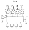
- Fig. 4 shows the internal structure of a lens body according to the first embodiment.
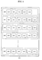
- Fig. 5 shows the internal structure of memory according to the first embodiment.
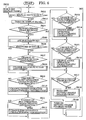
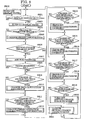
- Fig. 6 is a flowchart showing a display operation according to the first embodiment.
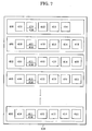
- Fig. 7 shows the internal structure of memory according to a second embodiment.
- Fig. 8 is a flowchart showing a display operation according to the second embodiment.
- Fig. 1 and Fig. 2 are a top view and a back view, respectively, of a TV lens.
- An image-capturing optical system is disposed inside a lens body 101, and a manual ring for manually controlling focus, zoom, and an iris mechanism is disposed outside the lens body 101.
- a drive unit 102 is removably attached to the lens body 101 and stores a motor for electrically driving the manual ring, a control board, a CPU, and the like.
- a seesaw switch 103 is used to servo-drive the zoom. Pressing the seesaw switch 103 to the T or W position, in Fig.
- a return switch 104 is for sending signals back to the camera according to the switching operation.
- a VTR switch 105 serves as a trigger for recording.
- the seesaw switch 103, the return switch 104, and the VTR switch 105 are the most basic switches for TV shooting, and have been arranged in the same positions, as shown, over the long history of TV lens to allow operability.
- a function switch A 106 can be assigned one of various functions related to image-capturing with the TV lens. For example, when a preset function is assigned to the function switch A 106, the camera operator can store the current zoom position by simultaneously pressing the function switch A 106 as well as a memory switch 108 described blow. A press of the function switch A 106 thus enables the zoom to return from any position to the stored position.
- a function switch B 107 can also be assigned one of various functions related to image-capturing with the TV lens. For example, a function for moving the zoom back and forth with a press of the switch can be assigned to the function switch B 107.
- the function switch B 107 can thus be used to assist focusing.
- the function switch A 106 and the function switch B 107 can be set such that they do not operate even when pressed.
- the memory switch 108 mentioned above is used to store, for example, the current zoom position, speed, and direction.
- a liquid-crystal display panel 109 is provided on the back of the drive unit 102.
- a display switch 110 is provided for switching between display and non-display modes of the display panel 109.
- the display switch 110 is designed to activate the display panel 109 only when necessary, thereby contributing to the reduction in power consumption.
- a function-setting switch 111 is provided for setting various functions related to image-capturing with the TV lens.
- Fig. 3 is an enlarged view of the function-setting switch 111.
- the function-setting switch 111 in Fig. 3 includes four arrow keys 202, 203, 204, and 205, and one selection key 201. By moving a cursor with the arrow keys 202 to 205, one of a plurality of functions is selected from a hierarchical menu on the display panel 109 and is confirmed with the selection key 201.
- a focus-lens optical system 301 for focus adjustment is driven by a focus motor 302.
- a focus-position-detecting unit 303 outputs position signals corresponding to the position of the focus-lens optical system 301.
- a focus-control unit 304 controls the focus-lens optical system 301.
- a zoom-lens optical system 305 for zoom adjustment is driven by a zoom motor 306.
- a zoom-position-detecting unit 307 outputs position signals corresponding to the position of the zoom-lens optical system 305.
- a zoom-control unit 308 controls the zoom-lens optical system 305.
- An iris blade 309 for iris adjustment is driven by an iris motor 310.
- An iris-position-detecting unit 311 outputs position signals corresponding to the position of the iris blade 309.
- An iris-control unit 312 controls the iris blade 309.
- An extender optical system 313 for extending the focal length by a factor of, for example, 1.5 or 2.0 is driven by an extender motor 314.
- An extender-position-detecting unit 315 outputs position signals corresponding to the position of the extender optical system 313.
- An extender-control unit 316 controls the extender optical system 313.
- a CPU 317 is responsible for control over the entire lens apparatus of the present embodiment.
- the liquid-crystal display panel 109 is on the back of the drive unit 102.
- the function-setting switch 111 is provided for setting various functions related to image-capturing with the TV lens.
- Memory 318 stores various functions and characteristics related to image-capturing with the TV lens.
- a first communication unit 319 is for communicating with various switches provided on the drive unit 102.
- a second communication unit 320 is for data communication with devices outside the lens.
- a third communication unit 321 is for dealing with various demands, and a fourth communication unit 322 is for communicating with
- Fig. 5 shows the internal structure of the memory 318.
- the memory 318 is divided into a plurality of user areas 400-409, each being assigned six function-setting subareas.
- the six subareas include a function-assignment information memory 410 for the assignment of functions to various switches provided on the drive unit 102, a preset-operation-characteristic information memory 411, an iris-operation-characteristic information memory 412, a zoom-operation-characteristic information memory 413, a focus-operation-characteristic information memory 414, and a password memory 415 for storing passwords to be used in setting-change disabled mode, in which the change of settings for each function is prohibited.
- a function-assignment information memory 410 for the assignment of functions to various switches provided on the drive unit 102
- a preset-operation-characteristic information memory 411 for the assignment of functions to various switches provided on the drive unit 102
- an iris-operation-characteristic information memory 412 for the assignment of functions to various switches provided on the drive unit
- each information memory (from 410 to 414) of the user areas (from 400 to 409) stores initial setting data as default setting information.
- the initial setting data stored in the information memory (from 410 to 414) of the user areas (from 401 to 409) other than the user area 400 is rewritten in accordance with the operation of the function-setting switch 111 in each changing step (S608, S610, S612, S614 and S616) of Fig. 6 described below and stored as user setting data in the information memory(from 410 to 414).
- step S601 it is determined whether or not the display switch 110 is ON (step S601). If it is determined that the display switch 110 is not ON, the display panel 109 is turned OFF (step S602). If it is determined in step S601 that the display switch 110 is ON, the display panel 109 is turned ON (step S603). It is then determined whether or not a setting-change disabled mode, where the change of user setting data is prohibited, is currently ON (step S604). If it is determined that the setting-change disabled mode is ON, password entry is requested (step S605). Then the password entered is compared with a password stored in the password memory to determine whether or not they match (step S606). If it is determined that the password entered does not match the password stored in the password memory, the process returns to step S605.
- step S604 If it is determined in step S604 that the setting-change disabled mode is not ON, or if it is determined in step S606 that the password entered matches the password stored in the password memory, it is determined whether or not the function-setting switch 111 is used to change the assignment of functions to various switches on the drive unit 102 (step S607). If the function-setting switch 111 is used to change the assignment of functions to various switches on the drive unit 102, the assignment of functions to the switches is changed (step S608) and the process proceeds to step S609. If the use of the function-setting switch 111 is not intended to change the assignment of functions to various switches on the drive unit 102, the process proceeds to step S609.
- step S609 it is determined whether or not the function-setting switch 111 is used to change preset operation characteristic information. If the function-setting switch 111 is used to change preset operation characteristic information, the preset operation characteristic information is changed (step S610) and the process proceeds to step S611. If the use of the function-setting switch 111 is not intended to change preset operation characteristic information, the process proceeds to step S611. Then, it is determined whether or not the function-setting switch 111 is used to change iris operation characteristic information (step S611). If the function-setting switch 111 is used to change iris operation characteristic information, the iris operation characteristic information is changed (step S612) and the process proceeds to step S613.
- step S613 it is determined whether or not the function-setting switch 111 is used to change zoom operation characteristic information. If the function-setting switch 111 is used to change zoom operation characteristic information, the zoom operation characteristic information is changed (step S614) and the process proceeds to step S615. If the use of the function-setting switch 111 is not intended to change zoom operation characteristic information, the process proceeds to step S615. Then, it is determined whether or not the function-setting switch 111 is used to change focus operation characteristic information (step S615).
- step S616 If the function-setting switch 111 is used to change focus operation characteristic information, the focus operation characteristic information is changed (step S616) and the process proceeds to step S617. If the use of the function-setting switch 111 is not intended to change focus operation characteristic information, the process proceeds to step S617. Then, it is determined whether or not the function-setting switch 111 is used to turn OFF the setting-change disabled mode for allowing the change of user setting data (step S617). If the function-setting switch 111 is used to turn OFF the setting-change disabled mode for allowing the change of user setting data, the function-setting switch 111 is turned OFF (step S618). If the function-setting switch 111 is used to turn ON the setting-change disabled mode for prohibiting the change of user setting data, the setting-change disabled mode is turned ON (step S619).
- setting information for each function related to image-capturing with the TV lens cannot be changed unless a password is entered.
- Another possible configuration is to turn ON and OFF the setting-change disabled mode by a special operation, such as simultaneously holding down the function switch A 106 and the function switch B 107 for three seconds or more.
- four arrow keys used as a function-setting switch in the present embodiment may be replaced with any other setting switch, such as a jog shuttle switch, that can be used for setting functions according to the flow displayed on the display panel.
- the display panel and the function-setting switch provided on the drive unit in the present embodiment may be arranged anywhere on the TV lens formed of the lens body and the drive unit.
- the first embodiment is configured such that no user setting data can be changed when the change of user setting data is prohibited.
- effective use of a preset function can be achieved if the configuration allows for the change of preset information, such as preset position, preset speed, and preset direction, that is stored in a preset-operation-characteristic information memory.
- FIG. 1 to 4 A second embodiment of the present invention will now be described in detail with reference to the drawings.
- the structures shown in Figs. 1 to 4 which are the same as those of the first embodiment, will not be described here. What will be described here are the differences, that is, the internal structure of the memory 318, the operation, the use of the display panel 109 and the function-setting switch 111, for setting functions related to the operating characteristics of the lens, and the operation for writing and rewriting such functions to the memory 318.
- Fig. 7 illustrates the internal structure of the memory 318.
- the descriptions of user areas 400 to 409 and memories 410 to 415 will be omitted, as they are the same as those in the first embodiment.
- a preset information submemory 416 provided within the preset-operation-characteristic information memory 411 is for storing preset information, such as preset position, preset speed, and preset direction.
- step S801 it is determined whether or not the display switch 110 is ON (step S801). If it is determined that the display switch 110 is not ON, the display panel 109 is turned OFF (step S802). If it is determined in step S801 that the display switch 110 is ON, the display panel 109 is turned ON (step S803). It is then determined whether or not the function-setting switch 111 is used to change the preset information (step S804). If the function-setting switch 111 is used to change the preset information, the preset information is changed (step S805) and the process proceeds to step S806. If the use of the function-setting switch 111 is not intended to change the preset information, the process proceeds to step S806.
- step S806 It is then determined whether or not a setting-change disabled mode, where change of user setting data is prohibited, is currently ON (step S806). If it is determined that the setting-change disabled mode is ON, password entry is requested (step S807). Then the password entered is compared with a password stored in the password memory to determine whether or not they match (step S808). If it is determined that the password entered does not match the password stored in the password memory, the process returns to step S807.
- step S806 If it is determined in step S806 that the setting-change disabled mode is not ON, or if it is determined in step S808 that the password entered matches the password stored in the password memory, it is determined whether or not the function-setting switch 111 is used to change the assignment of functions to various switches on the drive unit 102 (step S809). If the function-setting switch 111 is used to change the assignment of functions to various switches on the drive unit 102, the assignment of functions to the switches is changed (step S810) and the process proceeds to step S811. If the use of the function-setting switch 111 is not intended to change the assignment of functions to various switches on the drive unit 102, the process proceeds to step S811.
- step S811 it is determined whether or not the function-setting switch 111 is used to change preset operation characteristic information. If the function-setting switch 111 is used to change preset operation characteristic information, the preset operation characteristic information is changed (step S812) and the process proceeds to step S813. If the use of the function-setting switch 111 is not intended to change preset operation characteristic information, the process proceeds to step S813. Then, it is determined whether or not the function-setting switch 111 is used to change iris operation characteristic information (step S813). If the function-setting switch 111 is used to change iris operation characteristic information, the iris operation characteristic information is changed (step S814) and the process proceeds to step S815.
- step S815. it is determined whether or not the function-setting switch 111 is used to change zoom operation characteristic information (step S815). If the function-setting switch 111 is used to change zoom operation characteristic information, the zoom operation characteristic information is changed (step S816) and the process proceeds to step S817. If the use of the function-setting switch 111 is not intended to change zoom operation characteristic information, the process proceeds to step S817. Then, it is determined whether or not the function-setting switch 111 is used to change focus operation characteristic information (step S817).
- step S818 If the function-setting switch 111 is used to change focus operation characteristic information, the focus operation characteristic information is changed (step S818) and the process proceeds to step S819. If the use of the function-setting switch 111 is not intended to change focus operation characteristic information, the process proceeds to step S819. Then, it is determined whether or not the function-setting switch 111 is used to turn OFF the setting-change disabled mode for allowing the change of user setting data (step S819). If the function-setting switch 111 is used to turn OFF the setting-change disabled mode for allowing the change of user setting data, the function-setting switch 111 is turned OFF (step S820). If the function-setting switch 111 is used to turn ON the setting-change disabled mode for prohibiting the change of user setting data, the setting-change disabled mode is turned ON (step S821).
- setting information for each function related to image-capturing with the TV lens cannot be changed unless a password is entered.
- Another possible configuration is to turn ON and OFF the setting-change disabled mode by a special operation, such as simultaneously holding down the function switch A 106 and the function switch B 107 for three seconds or more.
- four arrow keys used as a function-setting switch in the present embodiment may be replaced with any other setting switch, such as a jog shuttle switch, that can be used for setting functions according to the flow displayed on the display panel.
- the display panel and the function-setting switch provided on the drive unit in the present embodiment may be arranged anywhere on the TV lens formed of the lens body and the drive unit.
Landscapes
- Engineering & Computer Science (AREA)
- Multimedia (AREA)
- Signal Processing (AREA)
- Physics & Mathematics (AREA)
- General Engineering & Computer Science (AREA)
- General Physics & Mathematics (AREA)
- Optics & Photonics (AREA)
- Studio Devices (AREA)
- Lens Barrels (AREA)
- Camera Bodies And Camera Details Or Accessories (AREA)
Applications Claiming Priority (2)
| Application Number | Priority Date | Filing Date | Title |
|---|---|---|---|
| JP2004115601 | 2004-04-09 | ||
| JP2004115601A JP4497990B2 (ja) | 2004-04-09 | 2004-04-09 | レンズ装置 |
Publications (2)
| Publication Number | Publication Date |
|---|---|
| EP1585319A1 EP1585319A1 (en) | 2005-10-12 |
| EP1585319B1 true EP1585319B1 (en) | 2010-03-17 |
Family
ID=34909545
Family Applications (1)
| Application Number | Title | Priority Date | Filing Date |
|---|---|---|---|
| EP05252227A Expired - Lifetime EP1585319B1 (en) | 2004-04-09 | 2005-04-08 | Lens apparatus |
Country Status (4)
| Country | Link |
|---|---|
| US (1) | US7265788B2 (enExample) |
| EP (1) | EP1585319B1 (enExample) |
| JP (1) | JP4497990B2 (enExample) |
| DE (1) | DE602005019940D1 (enExample) |
Families Citing this family (6)
| Publication number | Priority date | Publication date | Assignee | Title |
|---|---|---|---|---|
| JP2006054709A (ja) * | 2004-08-12 | 2006-02-23 | Fuji Photo Film Co Ltd | カメラシステム、カメラヘッドおよびカメラ本体 |
| JP5083855B2 (ja) * | 2006-01-30 | 2012-11-28 | ソニー株式会社 | 撮影装置 |
| JP4781296B2 (ja) * | 2007-02-20 | 2011-09-28 | キヤノン株式会社 | 撮像装置及びその制御方法及びプログラム及び記憶媒体 |
| JP5523013B2 (ja) * | 2009-08-18 | 2014-06-18 | キヤノン株式会社 | 撮像装置 |
| JP6235835B2 (ja) * | 2013-08-29 | 2017-11-22 | キヤノン株式会社 | レンズシステム及びそれを有する撮影装置 |
| JP6664213B2 (ja) * | 2015-12-25 | 2020-03-13 | キヤノン株式会社 | 撮像装置、レンズ装置、駆動装置、電子機器、ならびにそれらを有する撮影システム |
Family Cites Families (13)
| Publication number | Priority date | Publication date | Assignee | Title |
|---|---|---|---|---|
| EP0424678B1 (en) * | 1989-09-27 | 1996-09-04 | Canon Kabushiki Kaisha | Camera system controlling interchangeable lenses |
| JP3315555B2 (ja) | 1995-04-07 | 2002-08-19 | キヤノン株式会社 | カメラ制御装置 |
| JPH0996756A (ja) * | 1995-09-29 | 1997-04-08 | Canon Inc | レンズ装置及び撮像装置 |
| JPH09168115A (ja) * | 1995-12-15 | 1997-06-24 | Sony Corp | 撮像装置 |
| JP3762149B2 (ja) | 1998-07-31 | 2006-04-05 | キヤノン株式会社 | カメラ制御システム、カメラサーバ、カメラサーバの制御方法、カメラ制御方法、及びコンピュータ読み取り可能な記録媒体 |
| US6036137A (en) | 1998-12-17 | 2000-03-14 | Valmet-Karlstad Ab | Apparatus and method for winding paper |
| JP3420542B2 (ja) | 1999-10-28 | 2003-06-23 | キヤノン株式会社 | 光学装置、光学装置駆動ユニットおよびカメラシステム |
| JP3945115B2 (ja) * | 2000-03-07 | 2007-07-18 | コニカミノルタフォトイメージング株式会社 | デジタルカメラ、カメラボディ、撮像レンズおよび記録媒体 |
| JP2001290068A (ja) * | 2000-04-05 | 2001-10-19 | Canon Inc | 光学装置、光学装置駆動ユニットおよびカメラシステム |
| JP3450795B2 (ja) | 2000-04-05 | 2003-09-29 | キヤノン株式会社 | 光学装置、光学装置駆動ユニット、情報書込装置、プリセット情報設定システムおよびカメラシステム |
| JP4444488B2 (ja) * | 2000-12-08 | 2010-03-31 | キヤノン株式会社 | レンズ及び撮像システム |
| JP2003023488A (ja) * | 2001-07-09 | 2003-01-24 | Canon Inc | マルチファンクション端末装置 |
| JP4114348B2 (ja) * | 2001-12-03 | 2008-07-09 | 株式会社ニコン | 利用者識別機能を備える電子装置および識別方法 |
-
2004
- 2004-04-09 JP JP2004115601A patent/JP4497990B2/ja not_active Expired - Fee Related
-
2005
- 2005-04-04 US US11/098,270 patent/US7265788B2/en not_active Expired - Lifetime
- 2005-04-08 EP EP05252227A patent/EP1585319B1/en not_active Expired - Lifetime
- 2005-04-08 DE DE602005019940T patent/DE602005019940D1/de not_active Expired - Lifetime
Also Published As
| Publication number | Publication date |
|---|---|
| JP2005303609A (ja) | 2005-10-27 |
| DE602005019940D1 (de) | 2010-04-29 |
| EP1585319A1 (en) | 2005-10-12 |
| US20050225661A1 (en) | 2005-10-13 |
| US7265788B2 (en) | 2007-09-04 |
| JP4497990B2 (ja) | 2010-07-07 |
Similar Documents
| Publication | Publication Date | Title |
|---|---|---|
| JP5456851B2 (ja) | 回転スイッチ | |
| EP1585319B1 (en) | Lens apparatus | |
| JP2000284168A (ja) | レンズ駆動装置 | |
| US7268818B2 (en) | Optical apparatus with memories storing a default setting data and a user setting data | |
| CN103460102B (zh) | 镜头装置和控制聚焦的方法 | |
| EP1487198B1 (en) | Zoom lens apparatus and image-taking apparatus with zoom tracking capability | |
| JPH10325918A (ja) | ズームレンズ装置 | |
| US7388615B2 (en) | Lens apparatus allowing changing user settings to standard settings | |
| JP2001083399A (ja) | レンズ駆動装置及びレンズ装置 | |
| JP3873321B2 (ja) | テレビカメラ用ズームレンズ制御装置 | |
| US7764879B2 (en) | Control apparatus and imaging apparatus | |
| JP6235835B2 (ja) | レンズシステム及びそれを有する撮影装置 | |
| US20040189848A1 (en) | Operation apparatus and device for image-taking | |
| JP4366572B2 (ja) | レンズ制御システム | |
| JP4585789B2 (ja) | レンズ装置 | |
| JP2017003996A (ja) | 触感切替スイッチを有するデジタルカメラ 電気的に制御されるコントロールリングは全く新しい技術分野です。回転リングではなく、リングは固定されており、規制部材が回転するもので本願とは逆の技術をカイジするものです。また、逆のケースでは用いる技術も違っており、周知技術として用いられるものではなりません。 | |
| JP2017003996A6 (ja) | 触感切替スイッチを有するデジタルカメラ | |
| JP2004077706A (ja) | レンズシステム | |
| JP2017215405A (ja) | レンズシステム | |
| JP2004102000A (ja) | レンズ制御装置 | |
| KR200148532Y1 (ko) | 캠코더의 줌/포커스 조절장치 | |
| JP2737184B2 (ja) | カメラの焦点距離制御装置 | |
| JP2022120341A (ja) | 操作装置、レンズ装置、及び撮像装置 | |
| JPH11352382A (ja) | 光学装置 | |
| JP2014066878A (ja) | 撮像装置およびその制御方法 |
Legal Events
| Date | Code | Title | Description |
|---|---|---|---|
| PUAI | Public reference made under article 153(3) epc to a published international application that has entered the european phase |
Free format text: ORIGINAL CODE: 0009012 |
|
| AK | Designated contracting states |
Kind code of ref document: A1 Designated state(s): AT BE BG CH CY CZ DE DK EE ES FI FR GB GR HU IE IS IT LI LT LU MC NL PL PT RO SE SI SK TR |
|
| AX | Request for extension of the european patent |
Extension state: AL BA HR LV MK YU |
|
| 17P | Request for examination filed |
Effective date: 20060316 |
|
| AKX | Designation fees paid |
Designated state(s): DE FR GB NL |
|
| GRAP | Despatch of communication of intention to grant a patent |
Free format text: ORIGINAL CODE: EPIDOSNIGR1 |
|
| GRAS | Grant fee paid |
Free format text: ORIGINAL CODE: EPIDOSNIGR3 |
|
| GRAA | (expected) grant |
Free format text: ORIGINAL CODE: 0009210 |
|
| AK | Designated contracting states |
Kind code of ref document: B1 Designated state(s): DE FR GB NL |
|
| REG | Reference to a national code |
Ref country code: GB Ref legal event code: FG4D |
|
| REF | Corresponds to: |
Ref document number: 602005019940 Country of ref document: DE Date of ref document: 20100429 Kind code of ref document: P |
|
| REG | Reference to a national code |
Ref country code: NL Ref legal event code: VDEP Effective date: 20100317 |
|
| PG25 | Lapsed in a contracting state [announced via postgrant information from national office to epo] |
Ref country code: NL Free format text: LAPSE BECAUSE OF FAILURE TO SUBMIT A TRANSLATION OF THE DESCRIPTION OR TO PAY THE FEE WITHIN THE PRESCRIBED TIME-LIMIT Effective date: 20100317 |
|
| PLBE | No opposition filed within time limit |
Free format text: ORIGINAL CODE: 0009261 |
|
| STAA | Information on the status of an ep patent application or granted ep patent |
Free format text: STATUS: NO OPPOSITION FILED WITHIN TIME LIMIT |
|
| 26N | No opposition filed |
Effective date: 20101220 |
|
| REG | Reference to a national code |
Ref country code: FR Ref legal event code: PLFP Year of fee payment: 12 |
|
| PGFP | Annual fee paid to national office [announced via postgrant information from national office to epo] |
Ref country code: GB Payment date: 20160427 Year of fee payment: 12 Ref country code: DE Payment date: 20160430 Year of fee payment: 12 |
|
| PGFP | Annual fee paid to national office [announced via postgrant information from national office to epo] |
Ref country code: FR Payment date: 20160426 Year of fee payment: 12 |
|
| REG | Reference to a national code |
Ref country code: DE Ref legal event code: R119 Ref document number: 602005019940 Country of ref document: DE |
|
| GBPC | Gb: european patent ceased through non-payment of renewal fee |
Effective date: 20170408 |
|
| REG | Reference to a national code |
Ref country code: FR Ref legal event code: ST Effective date: 20171229 |
|
| PG25 | Lapsed in a contracting state [announced via postgrant information from national office to epo] |
Ref country code: FR Free format text: LAPSE BECAUSE OF NON-PAYMENT OF DUE FEES Effective date: 20170502 Ref country code: DE Free format text: LAPSE BECAUSE OF NON-PAYMENT OF DUE FEES Effective date: 20171103 |
|
| PG25 | Lapsed in a contracting state [announced via postgrant information from national office to epo] |
Ref country code: GB Free format text: LAPSE BECAUSE OF NON-PAYMENT OF DUE FEES Effective date: 20170408 |