EP1585116A2 - Appareil pour enregistrer des supports de type DVD à base de colorant et procédé d'enregistrement - Google Patents
Appareil pour enregistrer des supports de type DVD à base de colorant et procédé d'enregistrement Download PDFInfo
- Publication number
- EP1585116A2 EP1585116A2 EP05005169A EP05005169A EP1585116A2 EP 1585116 A2 EP1585116 A2 EP 1585116A2 EP 05005169 A EP05005169 A EP 05005169A EP 05005169 A EP05005169 A EP 05005169A EP 1585116 A2 EP1585116 A2 EP 1585116A2
- Authority
- EP
- European Patent Office
- Prior art keywords
- recording
- shortest
- pulse
- dye
- marks
- Prior art date
- Legal status (The legal status is an assumption and is not a legal conclusion. Google has not performed a legal analysis and makes no representation as to the accuracy of the status listed.)
- Granted
Links
Images


Classifications
-
- G—PHYSICS
- G11—INFORMATION STORAGE
- G11B—INFORMATION STORAGE BASED ON RELATIVE MOVEMENT BETWEEN RECORD CARRIER AND TRANSDUCER
- G11B7/00—Recording or reproducing by optical means, e.g. recording using a thermal beam of optical radiation by modifying optical properties or the physical structure, reproducing using an optical beam at lower power by sensing optical properties; Record carriers therefor
- G11B7/004—Recording, reproducing or erasing methods; Read, write or erase circuits therefor
- G11B7/0045—Recording
- G11B7/00456—Recording strategies, e.g. pulse sequences
-
- G—PHYSICS
- G11—INFORMATION STORAGE
- G11B—INFORMATION STORAGE BASED ON RELATIVE MOVEMENT BETWEEN RECORD CARRIER AND TRANSDUCER
- G11B7/00—Recording or reproducing by optical means, e.g. recording using a thermal beam of optical radiation by modifying optical properties or the physical structure, reproducing using an optical beam at lower power by sensing optical properties; Record carriers therefor
- G11B7/004—Recording, reproducing or erasing methods; Read, write or erase circuits therefor
- G11B7/0045—Recording
- G11B7/00451—Recording involving ablation of the recording layer
-
- G—PHYSICS
- G11—INFORMATION STORAGE
- G11B—INFORMATION STORAGE BASED ON RELATIVE MOVEMENT BETWEEN RECORD CARRIER AND TRANSDUCER
- G11B7/00—Recording or reproducing by optical means, e.g. recording using a thermal beam of optical radiation by modifying optical properties or the physical structure, reproducing using an optical beam at lower power by sensing optical properties; Record carriers therefor
- G11B7/004—Recording, reproducing or erasing methods; Read, write or erase circuits therefor
- G11B7/0045—Recording
- G11B7/00455—Recording involving reflectivity, absorption or colour changes
-
- G—PHYSICS
- G11—INFORMATION STORAGE
- G11B—INFORMATION STORAGE BASED ON RELATIVE MOVEMENT BETWEEN RECORD CARRIER AND TRANSDUCER
- G11B7/00—Recording or reproducing by optical means, e.g. recording using a thermal beam of optical radiation by modifying optical properties or the physical structure, reproducing using an optical beam at lower power by sensing optical properties; Record carriers therefor
- G11B7/24—Record carriers characterised by shape, structure or physical properties, or by the selection of the material
- G11B7/241—Record carriers characterised by shape, structure or physical properties, or by the selection of the material characterised by the selection of the material
- G11B7/242—Record carriers characterised by shape, structure or physical properties, or by the selection of the material characterised by the selection of the material of recording layers
- G11B7/244—Record carriers characterised by shape, structure or physical properties, or by the selection of the material characterised by the selection of the material of recording layers comprising organic materials only
- G11B7/246—Record carriers characterised by shape, structure or physical properties, or by the selection of the material characterised by the selection of the material of recording layers comprising organic materials only containing dyes
- G11B2007/24612—Record carriers characterised by shape, structure or physical properties, or by the selection of the material characterised by the selection of the material of recording layers comprising organic materials only containing dyes two or more dyes in one layer
-
- G—PHYSICS
- G11—INFORMATION STORAGE
- G11B—INFORMATION STORAGE BASED ON RELATIVE MOVEMENT BETWEEN RECORD CARRIER AND TRANSDUCER
- G11B7/00—Recording or reproducing by optical means, e.g. recording using a thermal beam of optical radiation by modifying optical properties or the physical structure, reproducing using an optical beam at lower power by sensing optical properties; Record carriers therefor
- G11B7/24—Record carriers characterised by shape, structure or physical properties, or by the selection of the material
- G11B7/241—Record carriers characterised by shape, structure or physical properties, or by the selection of the material characterised by the selection of the material
- G11B7/252—Record carriers characterised by shape, structure or physical properties, or by the selection of the material characterised by the selection of the material of layers other than recording layers
- G11B7/257—Record carriers characterised by shape, structure or physical properties, or by the selection of the material characterised by the selection of the material of layers other than recording layers of layers having properties involved in recording or reproduction, e.g. optical interference layers or sensitising layers or dielectric layers, which are protecting the recording layers
- G11B2007/25705—Record carriers characterised by shape, structure or physical properties, or by the selection of the material characterised by the selection of the material of layers other than recording layers of layers having properties involved in recording or reproduction, e.g. optical interference layers or sensitising layers or dielectric layers, which are protecting the recording layers consisting essentially of inorganic materials
- G11B2007/25706—Record carriers characterised by shape, structure or physical properties, or by the selection of the material characterised by the selection of the material of layers other than recording layers of layers having properties involved in recording or reproduction, e.g. optical interference layers or sensitising layers or dielectric layers, which are protecting the recording layers consisting essentially of inorganic materials containing transition metal elements (Zn, Fe, Co, Ni, Pt)
-
- G—PHYSICS
- G11—INFORMATION STORAGE
- G11B—INFORMATION STORAGE BASED ON RELATIVE MOVEMENT BETWEEN RECORD CARRIER AND TRANSDUCER
- G11B7/00—Recording or reproducing by optical means, e.g. recording using a thermal beam of optical radiation by modifying optical properties or the physical structure, reproducing using an optical beam at lower power by sensing optical properties; Record carriers therefor
- G11B7/24—Record carriers characterised by shape, structure or physical properties, or by the selection of the material
- G11B7/241—Record carriers characterised by shape, structure or physical properties, or by the selection of the material characterised by the selection of the material
- G11B7/252—Record carriers characterised by shape, structure or physical properties, or by the selection of the material characterised by the selection of the material of layers other than recording layers
- G11B7/257—Record carriers characterised by shape, structure or physical properties, or by the selection of the material characterised by the selection of the material of layers other than recording layers of layers having properties involved in recording or reproduction, e.g. optical interference layers or sensitising layers or dielectric layers, which are protecting the recording layers
- G11B2007/25705—Record carriers characterised by shape, structure or physical properties, or by the selection of the material characterised by the selection of the material of layers other than recording layers of layers having properties involved in recording or reproduction, e.g. optical interference layers or sensitising layers or dielectric layers, which are protecting the recording layers consisting essentially of inorganic materials
- G11B2007/25708—Record carriers characterised by shape, structure or physical properties, or by the selection of the material characterised by the selection of the material of layers other than recording layers of layers having properties involved in recording or reproduction, e.g. optical interference layers or sensitising layers or dielectric layers, which are protecting the recording layers consisting essentially of inorganic materials containing group 13 elements (B, Al, Ga)
-
- G—PHYSICS
- G11—INFORMATION STORAGE
- G11B—INFORMATION STORAGE BASED ON RELATIVE MOVEMENT BETWEEN RECORD CARRIER AND TRANSDUCER
- G11B7/00—Recording or reproducing by optical means, e.g. recording using a thermal beam of optical radiation by modifying optical properties or the physical structure, reproducing using an optical beam at lower power by sensing optical properties; Record carriers therefor
- G11B7/24—Record carriers characterised by shape, structure or physical properties, or by the selection of the material
- G11B7/241—Record carriers characterised by shape, structure or physical properties, or by the selection of the material characterised by the selection of the material
- G11B7/252—Record carriers characterised by shape, structure or physical properties, or by the selection of the material characterised by the selection of the material of layers other than recording layers
- G11B7/257—Record carriers characterised by shape, structure or physical properties, or by the selection of the material characterised by the selection of the material of layers other than recording layers of layers having properties involved in recording or reproduction, e.g. optical interference layers or sensitising layers or dielectric layers, which are protecting the recording layers
- G11B2007/25705—Record carriers characterised by shape, structure or physical properties, or by the selection of the material characterised by the selection of the material of layers other than recording layers of layers having properties involved in recording or reproduction, e.g. optical interference layers or sensitising layers or dielectric layers, which are protecting the recording layers consisting essentially of inorganic materials
- G11B2007/2571—Record carriers characterised by shape, structure or physical properties, or by the selection of the material characterised by the selection of the material of layers other than recording layers of layers having properties involved in recording or reproduction, e.g. optical interference layers or sensitising layers or dielectric layers, which are protecting the recording layers consisting essentially of inorganic materials containing group 14 elements except carbon (Si, Ge, Sn, Pb)
-
- G—PHYSICS
- G11—INFORMATION STORAGE
- G11B—INFORMATION STORAGE BASED ON RELATIVE MOVEMENT BETWEEN RECORD CARRIER AND TRANSDUCER
- G11B7/00—Recording or reproducing by optical means, e.g. recording using a thermal beam of optical radiation by modifying optical properties or the physical structure, reproducing using an optical beam at lower power by sensing optical properties; Record carriers therefor
- G11B7/24—Record carriers characterised by shape, structure or physical properties, or by the selection of the material
- G11B7/241—Record carriers characterised by shape, structure or physical properties, or by the selection of the material characterised by the selection of the material
- G11B7/252—Record carriers characterised by shape, structure or physical properties, or by the selection of the material characterised by the selection of the material of layers other than recording layers
- G11B7/257—Record carriers characterised by shape, structure or physical properties, or by the selection of the material characterised by the selection of the material of layers other than recording layers of layers having properties involved in recording or reproduction, e.g. optical interference layers or sensitising layers or dielectric layers, which are protecting the recording layers
- G11B2007/25705—Record carriers characterised by shape, structure or physical properties, or by the selection of the material characterised by the selection of the material of layers other than recording layers of layers having properties involved in recording or reproduction, e.g. optical interference layers or sensitising layers or dielectric layers, which are protecting the recording layers consisting essentially of inorganic materials
- G11B2007/25713—Record carriers characterised by shape, structure or physical properties, or by the selection of the material characterised by the selection of the material of layers other than recording layers of layers having properties involved in recording or reproduction, e.g. optical interference layers or sensitising layers or dielectric layers, which are protecting the recording layers consisting essentially of inorganic materials containing nitrogen
-
- G—PHYSICS
- G11—INFORMATION STORAGE
- G11B—INFORMATION STORAGE BASED ON RELATIVE MOVEMENT BETWEEN RECORD CARRIER AND TRANSDUCER
- G11B7/00—Recording or reproducing by optical means, e.g. recording using a thermal beam of optical radiation by modifying optical properties or the physical structure, reproducing using an optical beam at lower power by sensing optical properties; Record carriers therefor
- G11B7/24—Record carriers characterised by shape, structure or physical properties, or by the selection of the material
- G11B7/241—Record carriers characterised by shape, structure or physical properties, or by the selection of the material characterised by the selection of the material
- G11B7/252—Record carriers characterised by shape, structure or physical properties, or by the selection of the material characterised by the selection of the material of layers other than recording layers
- G11B7/257—Record carriers characterised by shape, structure or physical properties, or by the selection of the material characterised by the selection of the material of layers other than recording layers of layers having properties involved in recording or reproduction, e.g. optical interference layers or sensitising layers or dielectric layers, which are protecting the recording layers
- G11B2007/25705—Record carriers characterised by shape, structure or physical properties, or by the selection of the material characterised by the selection of the material of layers other than recording layers of layers having properties involved in recording or reproduction, e.g. optical interference layers or sensitising layers or dielectric layers, which are protecting the recording layers consisting essentially of inorganic materials
- G11B2007/25715—Record carriers characterised by shape, structure or physical properties, or by the selection of the material characterised by the selection of the material of layers other than recording layers of layers having properties involved in recording or reproduction, e.g. optical interference layers or sensitising layers or dielectric layers, which are protecting the recording layers consisting essentially of inorganic materials containing oxygen
-
- G—PHYSICS
- G11—INFORMATION STORAGE
- G11B—INFORMATION STORAGE BASED ON RELATIVE MOVEMENT BETWEEN RECORD CARRIER AND TRANSDUCER
- G11B7/00—Recording or reproducing by optical means, e.g. recording using a thermal beam of optical radiation by modifying optical properties or the physical structure, reproducing using an optical beam at lower power by sensing optical properties; Record carriers therefor
- G11B7/24—Record carriers characterised by shape, structure or physical properties, or by the selection of the material
- G11B7/241—Record carriers characterised by shape, structure or physical properties, or by the selection of the material characterised by the selection of the material
- G11B7/252—Record carriers characterised by shape, structure or physical properties, or by the selection of the material characterised by the selection of the material of layers other than recording layers
- G11B7/257—Record carriers characterised by shape, structure or physical properties, or by the selection of the material characterised by the selection of the material of layers other than recording layers of layers having properties involved in recording or reproduction, e.g. optical interference layers or sensitising layers or dielectric layers, which are protecting the recording layers
- G11B2007/25705—Record carriers characterised by shape, structure or physical properties, or by the selection of the material characterised by the selection of the material of layers other than recording layers of layers having properties involved in recording or reproduction, e.g. optical interference layers or sensitising layers or dielectric layers, which are protecting the recording layers consisting essentially of inorganic materials
- G11B2007/25718—Record carriers characterised by shape, structure or physical properties, or by the selection of the material characterised by the selection of the material of layers other than recording layers of layers having properties involved in recording or reproduction, e.g. optical interference layers or sensitising layers or dielectric layers, which are protecting the recording layers consisting essentially of inorganic materials containing halides (F, Cl, Br, l)
-
- G—PHYSICS
- G11—INFORMATION STORAGE
- G11B—INFORMATION STORAGE BASED ON RELATIVE MOVEMENT BETWEEN RECORD CARRIER AND TRANSDUCER
- G11B7/00—Recording or reproducing by optical means, e.g. recording using a thermal beam of optical radiation by modifying optical properties or the physical structure, reproducing using an optical beam at lower power by sensing optical properties; Record carriers therefor
- G11B7/24—Record carriers characterised by shape, structure or physical properties, or by the selection of the material
- G11B7/241—Record carriers characterised by shape, structure or physical properties, or by the selection of the material characterised by the selection of the material
- G11B7/242—Record carriers characterised by shape, structure or physical properties, or by the selection of the material characterised by the selection of the material of recording layers
- G11B7/244—Record carriers characterised by shape, structure or physical properties, or by the selection of the material characterised by the selection of the material of recording layers comprising organic materials only
- G11B7/245—Record carriers characterised by shape, structure or physical properties, or by the selection of the material characterised by the selection of the material of recording layers comprising organic materials only containing a polymeric component
-
- G—PHYSICS
- G11—INFORMATION STORAGE
- G11B—INFORMATION STORAGE BASED ON RELATIVE MOVEMENT BETWEEN RECORD CARRIER AND TRANSDUCER
- G11B7/00—Recording or reproducing by optical means, e.g. recording using a thermal beam of optical radiation by modifying optical properties or the physical structure, reproducing using an optical beam at lower power by sensing optical properties; Record carriers therefor
- G11B7/24—Record carriers characterised by shape, structure or physical properties, or by the selection of the material
- G11B7/241—Record carriers characterised by shape, structure or physical properties, or by the selection of the material characterised by the selection of the material
- G11B7/242—Record carriers characterised by shape, structure or physical properties, or by the selection of the material characterised by the selection of the material of recording layers
- G11B7/244—Record carriers characterised by shape, structure or physical properties, or by the selection of the material characterised by the selection of the material of recording layers comprising organic materials only
- G11B7/246—Record carriers characterised by shape, structure or physical properties, or by the selection of the material characterised by the selection of the material of recording layers comprising organic materials only containing dyes
- G11B7/2463—Record carriers characterised by shape, structure or physical properties, or by the selection of the material characterised by the selection of the material of recording layers comprising organic materials only containing dyes azulene
-
- G—PHYSICS
- G11—INFORMATION STORAGE
- G11B—INFORMATION STORAGE BASED ON RELATIVE MOVEMENT BETWEEN RECORD CARRIER AND TRANSDUCER
- G11B7/00—Recording or reproducing by optical means, e.g. recording using a thermal beam of optical radiation by modifying optical properties or the physical structure, reproducing using an optical beam at lower power by sensing optical properties; Record carriers therefor
- G11B7/24—Record carriers characterised by shape, structure or physical properties, or by the selection of the material
- G11B7/241—Record carriers characterised by shape, structure or physical properties, or by the selection of the material characterised by the selection of the material
- G11B7/242—Record carriers characterised by shape, structure or physical properties, or by the selection of the material characterised by the selection of the material of recording layers
- G11B7/244—Record carriers characterised by shape, structure or physical properties, or by the selection of the material characterised by the selection of the material of recording layers comprising organic materials only
- G11B7/246—Record carriers characterised by shape, structure or physical properties, or by the selection of the material characterised by the selection of the material of recording layers comprising organic materials only containing dyes
- G11B7/2467—Record carriers characterised by shape, structure or physical properties, or by the selection of the material characterised by the selection of the material of recording layers comprising organic materials only containing dyes azo-dyes
-
- G—PHYSICS
- G11—INFORMATION STORAGE
- G11B—INFORMATION STORAGE BASED ON RELATIVE MOVEMENT BETWEEN RECORD CARRIER AND TRANSDUCER
- G11B7/00—Recording or reproducing by optical means, e.g. recording using a thermal beam of optical radiation by modifying optical properties or the physical structure, reproducing using an optical beam at lower power by sensing optical properties; Record carriers therefor
- G11B7/24—Record carriers characterised by shape, structure or physical properties, or by the selection of the material
- G11B7/241—Record carriers characterised by shape, structure or physical properties, or by the selection of the material characterised by the selection of the material
- G11B7/242—Record carriers characterised by shape, structure or physical properties, or by the selection of the material characterised by the selection of the material of recording layers
- G11B7/244—Record carriers characterised by shape, structure or physical properties, or by the selection of the material characterised by the selection of the material of recording layers comprising organic materials only
- G11B7/246—Record carriers characterised by shape, structure or physical properties, or by the selection of the material characterised by the selection of the material of recording layers comprising organic materials only containing dyes
- G11B7/247—Record carriers characterised by shape, structure or physical properties, or by the selection of the material characterised by the selection of the material of recording layers comprising organic materials only containing dyes methine or polymethine dyes
- G11B7/2472—Record carriers characterised by shape, structure or physical properties, or by the selection of the material characterised by the selection of the material of recording layers comprising organic materials only containing dyes methine or polymethine dyes cyanine
-
- G—PHYSICS
- G11—INFORMATION STORAGE
- G11B—INFORMATION STORAGE BASED ON RELATIVE MOVEMENT BETWEEN RECORD CARRIER AND TRANSDUCER
- G11B7/00—Recording or reproducing by optical means, e.g. recording using a thermal beam of optical radiation by modifying optical properties or the physical structure, reproducing using an optical beam at lower power by sensing optical properties; Record carriers therefor
- G11B7/24—Record carriers characterised by shape, structure or physical properties, or by the selection of the material
- G11B7/241—Record carriers characterised by shape, structure or physical properties, or by the selection of the material characterised by the selection of the material
- G11B7/242—Record carriers characterised by shape, structure or physical properties, or by the selection of the material characterised by the selection of the material of recording layers
- G11B7/244—Record carriers characterised by shape, structure or physical properties, or by the selection of the material characterised by the selection of the material of recording layers comprising organic materials only
- G11B7/246—Record carriers characterised by shape, structure or physical properties, or by the selection of the material characterised by the selection of the material of recording layers comprising organic materials only containing dyes
- G11B7/248—Record carriers characterised by shape, structure or physical properties, or by the selection of the material characterised by the selection of the material of recording layers comprising organic materials only containing dyes porphines; azaporphines, e.g. phthalocyanines
-
- G—PHYSICS
- G11—INFORMATION STORAGE
- G11B—INFORMATION STORAGE BASED ON RELATIVE MOVEMENT BETWEEN RECORD CARRIER AND TRANSDUCER
- G11B7/00—Recording or reproducing by optical means, e.g. recording using a thermal beam of optical radiation by modifying optical properties or the physical structure, reproducing using an optical beam at lower power by sensing optical properties; Record carriers therefor
- G11B7/24—Record carriers characterised by shape, structure or physical properties, or by the selection of the material
- G11B7/241—Record carriers characterised by shape, structure or physical properties, or by the selection of the material characterised by the selection of the material
- G11B7/242—Record carriers characterised by shape, structure or physical properties, or by the selection of the material characterised by the selection of the material of recording layers
- G11B7/244—Record carriers characterised by shape, structure or physical properties, or by the selection of the material characterised by the selection of the material of recording layers comprising organic materials only
- G11B7/249—Record carriers characterised by shape, structure or physical properties, or by the selection of the material characterised by the selection of the material of recording layers comprising organic materials only containing organometallic compounds
-
- G—PHYSICS
- G11—INFORMATION STORAGE
- G11B—INFORMATION STORAGE BASED ON RELATIVE MOVEMENT BETWEEN RECORD CARRIER AND TRANSDUCER
- G11B7/00—Recording or reproducing by optical means, e.g. recording using a thermal beam of optical radiation by modifying optical properties or the physical structure, reproducing using an optical beam at lower power by sensing optical properties; Record carriers therefor
- G11B7/24—Record carriers characterised by shape, structure or physical properties, or by the selection of the material
- G11B7/241—Record carriers characterised by shape, structure or physical properties, or by the selection of the material characterised by the selection of the material
- G11B7/252—Record carriers characterised by shape, structure or physical properties, or by the selection of the material characterised by the selection of the material of layers other than recording layers
- G11B7/253—Record carriers characterised by shape, structure or physical properties, or by the selection of the material characterised by the selection of the material of layers other than recording layers of substrates
- G11B7/2531—Record carriers characterised by shape, structure or physical properties, or by the selection of the material characterised by the selection of the material of layers other than recording layers of substrates comprising glass
-
- G—PHYSICS
- G11—INFORMATION STORAGE
- G11B—INFORMATION STORAGE BASED ON RELATIVE MOVEMENT BETWEEN RECORD CARRIER AND TRANSDUCER
- G11B7/00—Recording or reproducing by optical means, e.g. recording using a thermal beam of optical radiation by modifying optical properties or the physical structure, reproducing using an optical beam at lower power by sensing optical properties; Record carriers therefor
- G11B7/24—Record carriers characterised by shape, structure or physical properties, or by the selection of the material
- G11B7/241—Record carriers characterised by shape, structure or physical properties, or by the selection of the material characterised by the selection of the material
- G11B7/252—Record carriers characterised by shape, structure or physical properties, or by the selection of the material characterised by the selection of the material of layers other than recording layers
- G11B7/253—Record carriers characterised by shape, structure or physical properties, or by the selection of the material characterised by the selection of the material of layers other than recording layers of substrates
- G11B7/2532—Record carriers characterised by shape, structure or physical properties, or by the selection of the material characterised by the selection of the material of layers other than recording layers of substrates comprising metals
-
- G—PHYSICS
- G11—INFORMATION STORAGE
- G11B—INFORMATION STORAGE BASED ON RELATIVE MOVEMENT BETWEEN RECORD CARRIER AND TRANSDUCER
- G11B7/00—Recording or reproducing by optical means, e.g. recording using a thermal beam of optical radiation by modifying optical properties or the physical structure, reproducing using an optical beam at lower power by sensing optical properties; Record carriers therefor
- G11B7/24—Record carriers characterised by shape, structure or physical properties, or by the selection of the material
- G11B7/241—Record carriers characterised by shape, structure or physical properties, or by the selection of the material characterised by the selection of the material
- G11B7/252—Record carriers characterised by shape, structure or physical properties, or by the selection of the material characterised by the selection of the material of layers other than recording layers
- G11B7/253—Record carriers characterised by shape, structure or physical properties, or by the selection of the material characterised by the selection of the material of layers other than recording layers of substrates
- G11B7/2533—Record carriers characterised by shape, structure or physical properties, or by the selection of the material characterised by the selection of the material of layers other than recording layers of substrates comprising resins
- G11B7/2534—Record carriers characterised by shape, structure or physical properties, or by the selection of the material characterised by the selection of the material of layers other than recording layers of substrates comprising resins polycarbonates [PC]
-
- G—PHYSICS
- G11—INFORMATION STORAGE
- G11B—INFORMATION STORAGE BASED ON RELATIVE MOVEMENT BETWEEN RECORD CARRIER AND TRANSDUCER
- G11B7/00—Recording or reproducing by optical means, e.g. recording using a thermal beam of optical radiation by modifying optical properties or the physical structure, reproducing using an optical beam at lower power by sensing optical properties; Record carriers therefor
- G11B7/24—Record carriers characterised by shape, structure or physical properties, or by the selection of the material
- G11B7/241—Record carriers characterised by shape, structure or physical properties, or by the selection of the material characterised by the selection of the material
- G11B7/252—Record carriers characterised by shape, structure or physical properties, or by the selection of the material characterised by the selection of the material of layers other than recording layers
- G11B7/253—Record carriers characterised by shape, structure or physical properties, or by the selection of the material characterised by the selection of the material of layers other than recording layers of substrates
- G11B7/2533—Record carriers characterised by shape, structure or physical properties, or by the selection of the material characterised by the selection of the material of layers other than recording layers of substrates comprising resins
- G11B7/2535—Record carriers characterised by shape, structure or physical properties, or by the selection of the material characterised by the selection of the material of layers other than recording layers of substrates comprising resins polyesters, e.g. PET, PETG or PEN
-
- G—PHYSICS
- G11—INFORMATION STORAGE
- G11B—INFORMATION STORAGE BASED ON RELATIVE MOVEMENT BETWEEN RECORD CARRIER AND TRANSDUCER
- G11B7/00—Recording or reproducing by optical means, e.g. recording using a thermal beam of optical radiation by modifying optical properties or the physical structure, reproducing using an optical beam at lower power by sensing optical properties; Record carriers therefor
- G11B7/24—Record carriers characterised by shape, structure or physical properties, or by the selection of the material
- G11B7/241—Record carriers characterised by shape, structure or physical properties, or by the selection of the material characterised by the selection of the material
- G11B7/252—Record carriers characterised by shape, structure or physical properties, or by the selection of the material characterised by the selection of the material of layers other than recording layers
- G11B7/254—Record carriers characterised by shape, structure or physical properties, or by the selection of the material characterised by the selection of the material of layers other than recording layers of protective topcoat layers
- G11B7/2542—Record carriers characterised by shape, structure or physical properties, or by the selection of the material characterised by the selection of the material of layers other than recording layers of protective topcoat layers consisting essentially of organic resins
-
- G—PHYSICS
- G11—INFORMATION STORAGE
- G11B—INFORMATION STORAGE BASED ON RELATIVE MOVEMENT BETWEEN RECORD CARRIER AND TRANSDUCER
- G11B7/00—Recording or reproducing by optical means, e.g. recording using a thermal beam of optical radiation by modifying optical properties or the physical structure, reproducing using an optical beam at lower power by sensing optical properties; Record carriers therefor
- G11B7/24—Record carriers characterised by shape, structure or physical properties, or by the selection of the material
- G11B7/241—Record carriers characterised by shape, structure or physical properties, or by the selection of the material characterised by the selection of the material
- G11B7/252—Record carriers characterised by shape, structure or physical properties, or by the selection of the material characterised by the selection of the material of layers other than recording layers
- G11B7/256—Record carriers characterised by shape, structure or physical properties, or by the selection of the material characterised by the selection of the material of layers other than recording layers of layers improving adhesion between layers
-
- G—PHYSICS
- G11—INFORMATION STORAGE
- G11B—INFORMATION STORAGE BASED ON RELATIVE MOVEMENT BETWEEN RECORD CARRIER AND TRANSDUCER
- G11B7/00—Recording or reproducing by optical means, e.g. recording using a thermal beam of optical radiation by modifying optical properties or the physical structure, reproducing using an optical beam at lower power by sensing optical properties; Record carriers therefor
- G11B7/24—Record carriers characterised by shape, structure or physical properties, or by the selection of the material
- G11B7/241—Record carriers characterised by shape, structure or physical properties, or by the selection of the material characterised by the selection of the material
- G11B7/252—Record carriers characterised by shape, structure or physical properties, or by the selection of the material characterised by the selection of the material of layers other than recording layers
- G11B7/257—Record carriers characterised by shape, structure or physical properties, or by the selection of the material characterised by the selection of the material of layers other than recording layers of layers having properties involved in recording or reproduction, e.g. optical interference layers or sensitising layers or dielectric layers, which are protecting the recording layers
- G11B7/2572—Record carriers characterised by shape, structure or physical properties, or by the selection of the material characterised by the selection of the material of layers other than recording layers of layers having properties involved in recording or reproduction, e.g. optical interference layers or sensitising layers or dielectric layers, which are protecting the recording layers consisting essentially of organic materials
- G11B7/2575—Record carriers characterised by shape, structure or physical properties, or by the selection of the material characterised by the selection of the material of layers other than recording layers of layers having properties involved in recording or reproduction, e.g. optical interference layers or sensitising layers or dielectric layers, which are protecting the recording layers consisting essentially of organic materials resins
-
- G—PHYSICS
- G11—INFORMATION STORAGE
- G11B—INFORMATION STORAGE BASED ON RELATIVE MOVEMENT BETWEEN RECORD CARRIER AND TRANSDUCER
- G11B7/00—Recording or reproducing by optical means, e.g. recording using a thermal beam of optical radiation by modifying optical properties or the physical structure, reproducing using an optical beam at lower power by sensing optical properties; Record carriers therefor
- G11B7/24—Record carriers characterised by shape, structure or physical properties, or by the selection of the material
- G11B7/241—Record carriers characterised by shape, structure or physical properties, or by the selection of the material characterised by the selection of the material
- G11B7/252—Record carriers characterised by shape, structure or physical properties, or by the selection of the material characterised by the selection of the material of layers other than recording layers
- G11B7/257—Record carriers characterised by shape, structure or physical properties, or by the selection of the material characterised by the selection of the material of layers other than recording layers of layers having properties involved in recording or reproduction, e.g. optical interference layers or sensitising layers or dielectric layers, which are protecting the recording layers
- G11B7/2578—Record carriers characterised by shape, structure or physical properties, or by the selection of the material characterised by the selection of the material of layers other than recording layers of layers having properties involved in recording or reproduction, e.g. optical interference layers or sensitising layers or dielectric layers, which are protecting the recording layers consisting essentially of inorganic materials
-
- G—PHYSICS
- G11—INFORMATION STORAGE
- G11B—INFORMATION STORAGE BASED ON RELATIVE MOVEMENT BETWEEN RECORD CARRIER AND TRANSDUCER
- G11B7/00—Recording or reproducing by optical means, e.g. recording using a thermal beam of optical radiation by modifying optical properties or the physical structure, reproducing using an optical beam at lower power by sensing optical properties; Record carriers therefor
- G11B7/24—Record carriers characterised by shape, structure or physical properties, or by the selection of the material
- G11B7/241—Record carriers characterised by shape, structure or physical properties, or by the selection of the material characterised by the selection of the material
- G11B7/252—Record carriers characterised by shape, structure or physical properties, or by the selection of the material characterised by the selection of the material of layers other than recording layers
- G11B7/258—Record carriers characterised by shape, structure or physical properties, or by the selection of the material characterised by the selection of the material of layers other than recording layers of reflective layers
- G11B7/2585—Record carriers characterised by shape, structure or physical properties, or by the selection of the material characterised by the selection of the material of layers other than recording layers of reflective layers based on aluminium
-
- G—PHYSICS
- G11—INFORMATION STORAGE
- G11B—INFORMATION STORAGE BASED ON RELATIVE MOVEMENT BETWEEN RECORD CARRIER AND TRANSDUCER
- G11B7/00—Recording or reproducing by optical means, e.g. recording using a thermal beam of optical radiation by modifying optical properties or the physical structure, reproducing using an optical beam at lower power by sensing optical properties; Record carriers therefor
- G11B7/24—Record carriers characterised by shape, structure or physical properties, or by the selection of the material
- G11B7/241—Record carriers characterised by shape, structure or physical properties, or by the selection of the material characterised by the selection of the material
- G11B7/252—Record carriers characterised by shape, structure or physical properties, or by the selection of the material characterised by the selection of the material of layers other than recording layers
- G11B7/258—Record carriers characterised by shape, structure or physical properties, or by the selection of the material characterised by the selection of the material of layers other than recording layers of reflective layers
- G11B7/259—Record carriers characterised by shape, structure or physical properties, or by the selection of the material characterised by the selection of the material of layers other than recording layers of reflective layers based on silver
-
- G—PHYSICS
- G11—INFORMATION STORAGE
- G11B—INFORMATION STORAGE BASED ON RELATIVE MOVEMENT BETWEEN RECORD CARRIER AND TRANSDUCER
- G11B7/00—Recording or reproducing by optical means, e.g. recording using a thermal beam of optical radiation by modifying optical properties or the physical structure, reproducing using an optical beam at lower power by sensing optical properties; Record carriers therefor
- G11B7/24—Record carriers characterised by shape, structure or physical properties, or by the selection of the material
- G11B7/241—Record carriers characterised by shape, structure or physical properties, or by the selection of the material characterised by the selection of the material
- G11B7/252—Record carriers characterised by shape, structure or physical properties, or by the selection of the material characterised by the selection of the material of layers other than recording layers
- G11B7/258—Record carriers characterised by shape, structure or physical properties, or by the selection of the material characterised by the selection of the material of layers other than recording layers of reflective layers
- G11B7/2595—Record carriers characterised by shape, structure or physical properties, or by the selection of the material characterised by the selection of the material of layers other than recording layers of reflective layers based on gold
Definitions
- the present invention relates to apparatuses and processes for recording dye-based recordable DVD media, wherein the recording layers of the DVD media cause changes in optical properties such as transmittance and reflectance through irradiating optical or laser beams, thereby enabling recording and reproducing information.
- DVD-R recordable digital versatile discs
- recording materials have been improved to micronize recording pits
- image compression formats such as MPEG2
- semiconductor lasers have been improved to shorten the wavelength for reading recording pits.
- dye-based recordable DVD media where pits or marks are formed by use of heat mode
- the pulse width and the recording power of laser pulse are optimized at a specific recording rate, thus there exist a problem that the marks and/or spaces are different at the other recording rates.
- dye-based recordable DVD media suffer from problems that mark widths are hardly uniform, mark lengths are often elongated or shortened, and jitter properties tend to degrade with time, since thermal capacity from heat pulses turns into insufficient that is required to form marks at edges, and the heating temperatures are different from the optimal decomposing temperature, therefore, the average length of marks tends to fluctuate and the duty ratio of optimal heating pulse comes to different.
- the format of DVD-R media is standardized through partially cutting the land portions of so-called land pre-pits.
- pre-pit information such as pre-pit addresses cannot be properly reproduced when the land pre-pit signal is less than 0.16; on the other hand, the land-pit signals themselves act noisily when the land pre-pit signal is more than 0.32 at data region, thus resulting in frequent occurrences of data errors.
- cut width should be adjusted with respect to the recording material by a stamper, which is a mold to transfer a signal recording portion of original pattern to resin substrates and is utilized at an injection molding cavity, and the land cut width should be adjusted so as to control the land pre-pit signal into the range of 0.16 to 0.32.
- JP-A No. 2004-195764 discloses employment of polymethine dyes or combination of polymethine dyes and optical stabilizers as recording material
- JP-A Nos. 09-309268 and 11-34499 disclose employment of a layer formed from tetraazaporphyrin (porphyrazin) dye or combination of cyanine dyes and azometalchelate dyes (salt forming dye) and a reflective layer as a recording layer
- JP-A No. 08-295079 discloses employment of formazane (metal chelate) dye and the other dyes as the recording material
- the apparatuses and processes for recording dye-based recordable DVD media according to the present invention provide new formats with recordable DVD systems that utilize semiconductor lasers having shorter oscillating wavelength compared to CD media, which feature may represent an effective way to eliminate unrecorded regions at additional data portions similarly to LPP system, and also may present an advantage that data errors are hardly induced due to precise control of fine cut width at preparing stampers and/or LPP signal leaks into data portion, accordingly the apparatuses and processes according to the present invention may satisfactorily applied to dye-based recordable DVD recording media and the like.
- the apparatus for recording a dye-based recordable DVD medium comprises a shortest mark recording unit, a second mark recording unit, and a cooling pulse irradiating unit, wherein the dye-based recordable DVD medium comprises a substrate and a recording layer formed on the substrate, the substrate comprises a guide groove to which wobble is formed, and the recording layer comprises at least an organic dye, the shortest mark recording unit is configured to record each of the shortest marks by use of one pulse beam of which the rear edge is more energized than the front edge, the second mark recording unit is configured to record each of the marks other than the shortest marks by use of one pulse beam of which the two sites of front and rear edges are energized, the cooling pulse irradiating unit is configured to irradiate cooling pulse laser beams onto the backwards of the respective pulse beams at 0.1 mW/pulse or less of optical energy.
- unrecorded regions may be reduced at additionally recording portions under a recording linear velocity of as high as 42 meters per second (hereinafter, expressed simply as "m/sec") or more, and also occurrences of data errors may be effectively prevented.
- m/sec recording linear velocity
- the process for recording a dye-based recordable DVD medium comprises recording shortest marks, recording second marks, and irradiating cooling pulses, wherein the dye-based recordable DVD medium comprises a substrate and a recording layer formed on the substrate, the substrate comprises a guide groove to which wobble is formed, and the recording layer comprises at least an organic dye, the recording shortest marks performs to record each of the shortest marks by use of one pulse beam of which the rear edge is more energized than the front edge, the recording second marks performs to record each of the marks other than the shortest marks by use of one pulse beam of which the two sites of front and rear edges are energized, the irradiating cooling pulses performs to irradiate cooling pulse laser beams onto the backwards of the respective pulse beams at 0.1 mW/pulse or less of optical energy.
- recordings may be performed to dye-based recordable DVD media while effectively preventing occurrences of data errors under a recording linear velocity of as high as 42 m/sec or more.
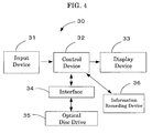
- the apparatus for regenerating a dye-based recordable DVD medium comprises an input device, control device, display device, interface, optical disc drive, information recording device, and the like, and is equipped with an operating system by which all of the devices in the apparatus are controlled. Accordingly, the dye-based recordable DVD medium recorded by the apparatus and/or process according to the present invention may be successfully regenerated.
- the dye-based recordable DVD medium according to the present invention is prepared by use of the apparatus and/or process according to the present invention, and may provide features that unrecorded regions are little at additionally recording portions and the recordings are of high quality without occurrences of data errors under a recording linear velocity of as high as 42 m/sec or more.
- the apparatuses for recording dye-based recordable DVD media according to the present invention are appropriately represented by the following first to fourth aspects.
- the apparatuses for recording dye-based recordable DVD media in the following first to fourth aspects are able to record in a recording layer formed on a substrate at a recording linear velocity of 42 m/sec or more by means of a unit configured to record shortest marks, a unit configured to record second marks, a unit configured to irradiate cooling pulses, and the other units selected properly depending on requirements.
- the processes for recording dye-based recordable DVD media according to the present invention are able to record in a recording layer formed on a substrate at a recording linear velocity of 42 m/sec or more by means of recording shortest marks, recording marks, irradiating cooling pulses, and the others selected properly depending on requirements.
- the processes for recording dye-based recordable DVD media according to the present invention can be properly performed by the apparatuses for recording dye-based recordable DVD media according to the present invention, the recording shortest marks can be properly performed by the shortest mark recording unit, the recording second marks can be properly performed by the second mark recording unit, the irradiating cooling pulses can be properly performed by the cooling pulse irradiating unit, and the others can be properly performed by the other units.
- the apparatus comprises a shortest mark recording unit, a second mark recording unit, and a cooling pulse irradiating unit
- the dye-based recordable DVD medium comprises a substrate and a recording layer formed on the substrate, the substrate comprises a guide groove to which wobble is formed, and the recording layer comprises at least an organic dye
- the shortest mark recording unit is configured to record each of the shortest marks by use of one pulse beam of which the rear edge is more energized than the front edge
- the second mark recording unit is configured to record each of the marks other than the shortest marks by use of one pulse beam of which the two sites of front and rear edges are energized
- the cooling pulse irradiating unit is configured to irradiate cooling pulse laser beams onto the backwards of the respective pulse beams at 0.1 mW/pulse or less of optical energy
- the recording of marks is performed on the recording layer at a recording linear velocity of 42 m/sec or more.
- the second mark recording unit is configured to record each of the second shortest marks and still longer marks by use of one pulse beam of which at least the rear edge among the front and rear edges is energized to the power that is substantially the same as that of the front edge of the shortest mark.
- the shortest mark recording unit, the cooling pulse irradiating unit, and the recording linear velocity are substantially the same with the first aspect.
- the second mark recording unit and the third mark recording unit are employed, the second mark recording unit is configured to record each of the second shortest marks by use of a pulse beam selected from a simple rectangular pulse beam of which the power is lower than the power of the shortest mark at any moments, a pulse beam of which the front edge is energized, and a pulse beam of which the rear edge is energized, and the third mark recording unit is configured to record each of the third shortest marks and still longer marks by use of one pulse beam of which the two sites of front and rear edges are energized.
- the shortest mark recording unit, the cooling pulse irradiating unit, and the recording linear velocity are substantially the same with the first aspect.
- the second mark recording unit and the third mark recording unit are employed, the second mark recording unit is configured to record each of the second shortest marks by use of one simple rectangular pulse beam of which the power is substantially the same as that of the front edge of the shortest mark, and the third mark recording unit is configured to record each of the third shortest marks and still longer marks by use of one pulse beam of which at least the rear edge among front and rear edges is energized, and the energized power is substantially the same as that of the front edge.
- the shortest mark recording unit, the cooling pulse irradiating unit, and the recording linear velocity are substantially the same with the first aspect.
- the first to fourth aspects of the processes for recording a dye-based recordable DVD medium may be properly performed by use of the first to fourth aspects of the apparatuses for recording a dye-based recordable DVD medium respectively.
- the apparatuses for recording dye-based recordable DVD media in the first aspect are able to record in a recording layer formed on a substrate at a recording linear velocity of 42 m/sec or more by means of a unit configured to record shortest marks, a unit configured to record second marks, a unit configured to irradiate cooling pulses, and the other units selected properly depending on requirements.
- the substrate performs as a support on which formed are a recording layer, a guide groove having wobble for tracking, and a convex-concave preformat for guide pits and address signals.
- the material of the substrate may be properly selected as long as the material is transparent for the laser beam when the recording-reproducing is carried out from the substrate side;
- examples of the material include plastics such as polyester resins, acrylic resins, polyamide resins, polycarbonate resins, polyolefin resins, phenol resins, epoxy resins, and polyimide; glasses, ceramics, and metals.
- the shape of the substrate may be properly selected depending on the application as long as the shape is suited for the DVD recording-reproducing standard; for example, the substrate is disc shape of 120 mm diameter and thickness of 0.1 mm, 0.6 mm, or 1.2 mm.
- Gate signals may be provided from the wobble in place of LPP (land pre-pit) detection employed in preformats of DVD-RW and disc rotating control.
- the gate signals may be properly selected depending on the application; the basic clock cycle T for identifying the wobble frequency is about 0.133 ⁇ m or about 38 nsec in the case of 4.7 GB DVD.
- the frequency band of the wobble corresponds to 150T to 400T in general.
- the frequency band may not be suitable for higher density recording when data are added to record by frequency modulation or phase modulation since significant spaces inevitably exist between the prior data and the data to be additionally recorded.
- LPP are provided in recordable DVD-R, and the recording sites are controlled by the LPP signals.
- the optimum signal amplitude is defined to be 0.18 ⁇ LPPb ⁇ 0.26 in LPP. Accordingly, the cut width of lands should be controlled precisely at producing the stamper.
- the wobble cycle may be properly selected depending on the application; for example, the wobble cycle is 4T to 96T.
- the wobble cycle is less than 4T, the detection is likely to be difficult due to excessively low frequency, and the reliability as to rotation control and address detection may be insufficient, and when the wobble cycle is more than 96T, the spaces between the recording data is excessively wide, resulting in lower capacity or insufficient data processing rate.
- the wobble amplitude of the recordable DVD media in the present invention when the ratio of wobble amplitude Wo after passing through appropriate filters such as high filter at 4 MHz and low filter at 30 kHz to push-pull amplitude PP after passing through a filter at 30 kHz, i.e. Wo/PP, satisfies the relation 0.1 ⁇ Wo/PP ⁇ 0.4, the synchronization adjustment is relatively easy, preferably is 0.15 ⁇ Wo/PP ⁇ 0.3.
- the LPP type requires precise cut width control in order to adjust the LPP cut width into 0.18 to 0.26, whereas the wobble type in the present invention requires no more than the control of RF source and swing level, i.e. the circuit to control the swing level may adjust the swing level properly, therefore, the yields of stampers and DVD media can be increased remarkably.
- the groove depth is preferably 1000 to 2500 angstroms, more preferably is 1500 to 2000 angstroms in the case that recording layers are formed using an organic dye by solvent coating processes.
- the tracking may not be controlled appropriately due to insufficient push-pull signals, and then the grove depth is more than 2500 angstroms, the transferring ability may be deteriorated at molding substrates.
- the dye groove depth d1 when a dye recording layer is provided the following relation is preferable: 1200 ⁇ d1 ⁇ m ⁇ 160000 wherein mT: wobble frequency (m: natural number)
- the groove depth of substrates are typically limited by the transferring limit due to the substrate molding described above, thus the groove depth is limited to no more than 160000 in practice.
- the pitch of tracks is typically required to be 0.64 to 0.8 ⁇ m in order to assure the recording density of 4 to 5 GB.
- the groove width depends on the recording material in general; usually the half-width is 0.18 to 0.40 ⁇ m in almost organic materials.
- the recording layer is formed on a substrate, on which a guide groove are provided, and the wobble described above is formed on the guide grooves.
- the recording layer contains at least an organic dye as the main component and has an optical property so that irradiating laser beam induces an optical change that is utilized for recording and/or reproducing information.
- the optical property may be properly selected depending on the application; preferably, the refractive index "n" and the extinction coefficient "k" of the recording layer are 1.5 ⁇ n ⁇ 3.0 and 0.02 ⁇ k ⁇ 0.2, in a condition that the wavelength of the measured light is L ⁇ 5 nm, wherein L is the wavelength of pulse beam for recording and reproducing, and the recording layer is a monolayer.
- the recording sensitivity is likely to be lower, and when “k” is more than 0.2, the reflection level may be no more than 50 %.
- DVD-ROMs are typically standardized at near the wavelength of 650 nm; the wavelength of the pulse beam for recording media is standardized at 650 to 660 nm for popular applications in addition to 635 nm for authoring exclusive media.
- these wavelengths are no more than the targets, namely each of the wavelengths may be larger or smaller depending on the fluctuations at producing the semiconductor laser diode (LD) tips and the like.
- LDs typically tend to inherently increase the wavelength when temperature rises.
- the recording layer in the present invention is applicable within the wavelength range of 600 to 720 nm including the range described above in the first to the fourth aspects.
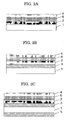
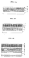
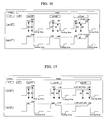
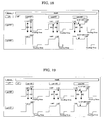
- the construction of recording layer may be properly selected depending on the application; for example, the construction may be the layer construction of usual recordable optical discs shown in FIGs. 1A to 1D, the layer construction of usual CD-R media shown in FIGs. 2A to 2C, and the layer construction of recordable DVD media shown in FIGs. 3A to 3C.
- the construction is preferable for the dye-based recordable DVD media that the first substrate and the second substrate as a protective layer are laminated with the recording layer interposed therebetween by means of an adhesive as shown in FIGs. 3B and 3C.
- the recording layer may be a monolayer of an organic dye-based layer, or may be a laminated layer of an organic dye-based layer and a reflective layer to increase the reflectivity. Further, an undercoat layer and/or a protective layer may be provided between the recording layer and the substrate; a protective substrate and/or a hard-coat layer may be provided on the substrate.
- Each of these layers may be of monolayer construction or of laminated construction of two or more layers. Among these constructions, the construction of "first substrate/organic dye layer/reflective layer/protective layer/adhesive layer/second substrate (protective substrate)" is preferable, which is one of the most popular constructions.
- reference numbers 1 to 8 designate 1: substrate, 2: recording layer, 3: undercoat layer, 4: protective layer, 5: hard coat layer, 6: reflective layer, 7: protective substrate, and 8: adhesive layer.
- the thickness of the entire recording layer may be properly selected depending on the application; preferably, the thickness is 100 angstroms to 10 ⁇ m, more preferably is 200 to 2000 angstroms.
- the material of the recording layer may be properly selected depending on the application, as long as the material contains an organic dye as one of the main components; for example, such materials are exemplified as the material of the recording layer that an amount of organic dye sufficient for recording and reproducing is included, and optional additives are included in relatively small amount depending on the requirements.
- organic dyes examples include azo compounds, formazan compounds, dipyrromethene compounds, (poly)methyne compounds, naphtalocyanine compounds, phtalocyanine compounds, tetraazaporphyrin compounds, squarylium compounds, chloconium compounds, pyrylium compounds, naphthoquinone compounds, anthraquinone compounds, indanthrene compounds, xanthene compounds, triphenylmethane compounds, azulene compounds, tetrahydrocoline compounds, phenanthrene compounds, triphenothiazine compounds, and metal complexes thereof.
- azo compounds formazan compounds, squarylium compounds, dipyrromethene compounds, trimethynecyanine compounds, tetraazaporphyrin compounds, and metal complexes thereof are preferable.
- the thermal decomposition property of these dyes may be properly selected depending on the application; preferably, the initial decomposition temperature or kick-off temperature is 100 to 360 °C, more preferably is 100 to 350 °C.
- the kick-off temperature is less than 100°C, the storage stability of discs may be deteriorated, and when the kick-off temperature is above 360 °C, the pits may not formed successfully, thus the jitter property may be lowered.
- the dyes described above may be added with another organic dye, metal, or metal compound, in order to improve the optical characteristics, recording sensitivity and/or signal characteristics.
- additional metals and metal compounds include In, Te, Bi, Se, Sb, Ge, Sn, Al, Be, TeO 2 , SnO, As and Cd.
- examples of the optional additives include polymer materials such as ionomer resins, polyamide resins, vinyl resins, natural polymers, silicones, and liquid rubbers; silane coupling agents, stabilizers such as transition metal complexes, dispersants, flame-retardants, lubricants, antistats, surfactants, and plasticizers.
- polymer materials such as ionomer resins, polyamide resins, vinyl resins, natural polymers, silicones, and liquid rubbers
- silane coupling agents such as transition metal complexes, dispersants, flame-retardants, lubricants, antistats, surfactants, and plasticizers.
- the method for producing the recording layers may be properly selected depending on the application, for example, such conventional methods are available as vapor deposition method, spattering method, CVD method, and coating method.
- the coating method may be carried out by dissolving materials described above in an organic solvent to form a coating liquid, then the coating liquid is processed by conventional coating method such as spray coating, roller coating, dip coating, and spin coating.
- the organic solvent may be properly selected depending on the application; examples of the organic solvent include alcohols such as methanol, ethanol, and isopropanol; ketones such as acetone, methyl ethyl ketone, and cyclohexanone; amides such as N,N-dimethylformamide and N,N-dimethylacetamide; sulfoxide such as dimethylsulfoxide; ethers such as tetrahydrofuran, dioxane, dimethylether, and ethyleneglycol monomethylether; esters such as methyl acetate and ethyl acetate; halogenated hydrocarbons such as chloroform, methylene chloride, dichloroethane, carbon tetrachloride, and trichloroethane; aromatics such as benzene, xylene, monochlorobenzene, and dichlorobenzene; cellosolve such as methoxy ethanol, ethoxy ethanol; and hydro
- the undercoat layer is disposed for the purposes of (1) improving the adhesion, (2) serving as a barrier layer against water or gases, (3) improving the shelf life of the recording layer, (4) improving the reflectivity of the recording layer, (5) protecting the substrate from solvents, and/or (6) forming guide grooves, guide pits, preformats, and the like.
- various polymer compounds such as ionomer resins, polyamide resins, vinyl resins, natural resins, natural polymers, silicones, and liquid rubbers, and silane coupling agents may be employed.
- inorganic compounds such as SiO, MgF 2 , SiO 2 , TiO 2 , ZnO, TiN, and SiN can be used in addition to the above-described polymer materials.
- metals and semimetals such as Zn, Cu, Ni, Cr, Ge, Se, Au, Ag, and Al can be used.
- metals such as Al and Ag, and organic thin films having a metal luster such as methine dye and xanthene dye may be used.
- an ultraviolet-curing resin, a thermosetting resin, and a thermoplastic resin can be used.
- the thickness of the undercoat layer may be properly selected depending on the application; preferably, the thickness is 0.01 to 30 ⁇ m, more preferably is 0.05 to 10 ⁇ m.
- the material of the reflective layer may be properly selected depending on the application; preferably, the material is selected from metals and semimetals exhibiting high reflectivity corrosion resistance such as Au, Ag, Cr, Ni, Al, Fe, and Sn. Among these metals, Au, Ag, and Al are particularly preferred in view of the reflectivity and the productivity. These metals and semimetals may be used alone or in combination as alloys.
- the thickness of the reflective layer may be properly selected depending on the application; preferably, the thickness is 50 to 5000 angstroms, more preferably is 100 to 3000 angstroms.
- the reflective layer may be formed by deposition, sputtering or the like.
- the protective layer and the hard coat layer on the substrate surface may be provided in order to (1) protect the recording layer or the reflection absorbing layer from scratches, dust, and contamination, (2) improve the shelf life of the recording layer or the reflection absorbing layer, and (3) improve the reflectivity. To satisfy these purposes, materials similar to those used for the undercoat layer may be used.
- thermoplastic materials thermosetting materials, and UV curable resins
- organic materials of thermoplastic materials, thermosetting materials, and UV curable resins are available such as polymethacrylate resins, polycarbonate resins, epoxy resins, polystyrene resins, polyester resins, vinyl resins, cellulose resins, aliphatic hydrocarbon resins, aromatic hydrocarbon resins, natural rubber, styrene-butadiene resins, chloroprene rubbers, waxes, alkyd resins, drying oils, and rosins.
- UV curable resins are preferable owing to the higher productivity.
- the thickness of the protective layer or the hard coat layer may be properly selected depending on the application; preferably, the thickness is 0.01 to 30 ⁇ m, more preferably is 0.05 to 10 ⁇ m.
- the protective layer or the hard coat layer on the substrate surface may be incorporated with a stabilizer, dispersant, flame retardant, lubricant, antistatic, surfactant, and/or plasticizer as is the case of the recording layer.
- the material of the adhesive layer may be properly selected depending on the application; preferably, the material of the adhesive layer is selected from UV curable adhesives and ho-melt adhesives owing to the productivity.
- the protective substrate is required to be transparent to a laser beam when the laser beam is irradiated through the substrate, otherwise the transparency is not required.
- the materials for the protective substrate are utterly the same as those for the substrate; for example, plastics such as polyesters, acrylic resins, polyamides, polycarbonate resins, polyolefin resins, phenol resins, epoxy resins, and polyimides; glass, ceramics, metals, and the like may be used.
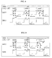
- the shortest mark recording unit performs recording by use of laser pulse in which the rear edge of the laser pulse is more energized than the front edge of the laser pulse.
- the shortest marks are the marks that have the shortest length to be recorded in the recording layer for detecting signals and the like.
- the length of the shortest marks is about 0.89 ⁇ m in CD, about 0.4 ⁇ m in DVD, and about 0.16 ⁇ m in BD (blu-ray disc) that utilize blue-violet laser beam of relatively short wavelength.
- BD blue-ray disc
- basic clock cycle T for identifying the wobble frequency is about 0.133 ⁇ m or about 38 nsec in the case of 4.7 GB DVD; therefore, the shortest marks are about 6.7T in CD, about 3T in DVD, and about 1.2T in BD; alternatively, the durations are about 254.6 nsec in CD, about 114 nsec in DVD, and about 45.6 nsec in BD.
- One of the objects in the present invention is to improve recording quality at higher linear velocity recording.
- uniform formation of the shortest marks typically effects on the resulting recording quality.
- each of the front edge of the shortest marks is made smaller than each of the rear edges of the shortest marks, which may reduce the effect of overshooting of laser pulse; each of the rear edges of the shortest marks is more energized than the other portions as well as the mark formation at the front edges of the shortest marks is made more uniform and stable, which may bring about higher quality of the resulting shortest marks.
- the duration of the laser pulse for recording the shortest marks may be properly selected depending on the application; preferably, the marks are as uniform as possible in order to enhance the recording quality at higher linear velocity recording, the power to form each of the rear edges of the laser pulse is more energized than the power to form each of the front edges.
- the length of the energized pulse for forming the rear edges is preferably 0.1T to 2.3T, more preferably is 0.3T to 1.8T.
- the length is less than 0.1T, the energized effect is not significant which is similar to the rectangular pulse, and when the length is more than 2.3T, excessive recording power is irradiated beyond the desirable pulse, i.e. overshooting is significant and the uniformity is likely to be deteriorated.
- W1/W0 is 1.01 to 1.50, more preferably is 1.05 to 1.30; wherein W0 is the power for the front edge of the shortest marks and W1 is the power for the rear edge of the shortest marks.
- the condition that W0 is less than W1 may mitigate the effect of overshooting.
- the overshooting is typically 1.05 to 1.30 in usual pickups, thus the W1/W0 is preferably controlled into 1.05 to 1.30 correspondingly.
- second mark recording is carried out such that the marks other than the shortest marks are recorded by use of laser pulses each of which is energized at both of front and rear edges.
- the marks are intended for recording data, information, or the like; the marks are desired to be as uniform as possible in order to enhance the recording quality at high linear velocity recording.
- the power for the mark recording may be properly selected depending on the application; preferably, W2/W3 is 1.05 to 3.00, more preferably is 1.10 to 2.00; wherein W2 is the additional power for both of front and rear edges, and W3 is the power without the additional power.
- W1/W2 is preferably 1.00 to 2.00, more preferably is 1.05 to 1.50.
- FIG. 6 shows an exemplary recording waveforms corresponding to the first aspect.
- FIG. 6 shows waveforms in which rear edge of the shortest mark is energized, the mark other than shortest mark is energized at two sites of the rear edge and front edge.
- this waveform rear edge of the shortest mark is energized and the mark other than shortest mark is energized at the rear edge and front edge, therefore both of asymmetry and jitter may be improved.
- the "asymmetry” relates to the data level shifted from central detecting site due to signal asymmetry in RF signals at pickup output of recording/regenerating apparatus, and the “asymmetry” is expressed by the ratio of the shifted level to the total amplitude.
- the shift may generate by disc or pickup properties.
- jitter refers to the frequency or rate of errors that occur in digital signal transmission; for example, when one error exists in one hundred data, the jitter or error rate is 1 %.
- the reason to partially energize the shortest marks and those other than the shortest marks is to avoid the adverse effect of the overshooting of recording pulses; namely, the front edge of laser pulse emitted from recording/regenerating apparatuses often causes overshooting, thus excessive recording power is emitted beyond the pre-determined level and also the pulses are usually unstable; such conditions typically deteriorate the recording property, in particular adversely effect on the shortest marks significantly during higher velocity recording.
- the power margin tends to decrease due to the difference of the power at which the lowest jitter is obtainable and the power at which the error is least.
- the recording power, at which the least jitter is obtainable in higher linear recording tends to induce the asymmetry of recording signals to minus side, and tends to cause errors even at lower jitter.
- the first to the fourth aspects of the present invention may address the problem due to lower asymmetry.
- the compensation of mark recording refers to the control of pulse width of recording marks so as to improve the recording/regenerating quality.
- the compensation is preferably performed through the first to the fourth aspects according to the present invention.
- the compensation may be properly selected depending on the application; for example, the compensation is performed as follows: when a mark of which just before the space is the shortest is to be recorded, the mark is examined whether the mark is the longest or not, and the heating pulse width at the front edge of the shortest mark is determined to be longer than the heating pulse width at the front edge of other than the shortest mark; alternatively, when the shortest mark is to be recorded, the space just before the mark is examined whether the space is the longest or not, and the heating pulse width at the front edge of the mark of which the immediately front space being shortest is determined to be shorter than the heating pulse width at the front edge of other than the shortest space.
- the method to determine the pulse width may be properly selected depending on the application, and the compensation level is preferably 0.02T to 0.10T.
- the space just before the mark to be recorded is of the shortest, and when the pulse width at the front edge of the mark is approximately the same with the pulse width of the other marks, the space length of the space just before the mark turns to shorter due to thermal influence, and the jitter may be somewhat deteriorated.
- the heating pulse width at the front edge is shortened, the effect is significant. Further, the shortening of the front edge of the heating pulse may effectively determine to shorten the pulse width.
- the compensation level or duration to control the heating pulse width at the front edge of the shortest mark to be longer than that of the other marks is 0.05T to 0.25T.
- the compensation to make long the pulse width at the front edge of the shortest mark may bring about recordings with lower jitter.
- the method other then the present invention to record one mark by use of plural pulses or multi pulses may possibly solve the problems associated with the lower asymmetry when the pulse beam is optimized.
- plural laser pulses will cause fluctuation in rising duration and falling duration, possibly resulting in fluctuation of recording quality. The higher is the linear recording, the more significant will be the fluctuation.
- the method to record one mark by use of one pulse may bring about an advantage that the fluctuation of recording quality is lower than the multi pulse method described above.
- the recording waveform simpler than that of the multi pulse method may allow to equalize easily the optical quantity at recording, and may allow address detection while equalizing not only the reflected optical quantity at spaces but also the optical quantity at marks, and also the address detection may be easily carried out advantageously even when cooling pulse of 0.1 mW or less is provided at the rear end of the pulse.
- a cooling pulse beam of 0.1 mW or less is irradiated.
- the irradiation of the cooling pulse beam may perform to sharpen well the mark edges especially when the recording power is raised, thereby the thermal influence between marks comes to remarkable, and the effect of overshooting turns to be more significant.
- the power for irradiating the cooling pulse beam may be properly selected within the range of 0.1 mW or less. When the power is more than 0.1 mW, the mark edge may not be sharpened successfully.
- the irradiation duration of the cooling pulse beam may be properly selected depending on the application; preferably, the irradiation duration is 1/6 to 6/6 of the irradiation duration of the shortest space, i.e. 6.3 to 38 nsec, which duration may improve the recording quality effectively.
- the irradiation duration is longer than 6/6 of the irradiation duration of the shortest space, the cooling area may possibly exceed the shortest space and extend to the next mark.
- the cooling pulse is not employed, the residual heat or the remaining thermal may influence the waveform, which may degrade the jitter property. Excessively short cooling may result in inferior jitter property as that of without cooling pulse.
- the jitter is 70 % when the recording is performed at 42 m/sec of recording linear velocity; and the effect of the irradiation duration is as follows. Namely, the jitter deteriorates significantly at the region below 1/6, preferable lower range is understood to be 1/6.
- shortening the pulse duration may lead to property improvement, the recording sensitivity may be deteriorated unless higher irradiating power is not provided. Therefore, the recording apparatuses that cannot irradiate at such higher power cannot record at higher velocity.
- the recording linear velocity means the linear velocity at recording site while rotating the substrate; the standard velocity is 3.49 m/sec, i.e. 42 m/sec of the recording linear velocity corresponds to so-called 12 times high velocity.
- the recording layer may record information with higher quality at a recording linear velocity of 42 m/sec or more.
- the recording apparatus may be properly selected depending on the application; for example, the recording apparatus may be generally available recording/regenerating apparatuses that utilize optical discs.
- optical discs utilized in the recording/regenerating apparatuses may be properly selected depending on the application; examples of the optical discs include DVD-RAM ⁇ WO, DVD-R, DVD+R, DVD-RAM, DVD-RW, and DVD+RW.
- the DVD-RAM ⁇ WO, DVD-R, and DVD+R are those capable of recording one time; and DVD-RAM, DVD-RW, and DVD+RW are those capable of recording plural times.
- the recording/regenerating apparatuses perform recording and/or regenerating on these optical discs.
- the recording/regenerating apparatus 30 comprises input device 31, control device 32, display device 33, interface 34, optical disc drive 35, information recording device 36, and the like as shown in FIG. 4.
- the recording/regenerating apparatus 30 equips an operating system (OS), which controls all of the devices mounted to the apparatus.
- OS operating system
- the input device 31 equips at least one input medium (not shown) such as a keyboard, mouth, and pointing device, and informs various information to control device 32. Further, CRT equipped with a touch panel may be available as an integrated device of display 33 and input device 31.
- the control device 32 is constructed from a CPU (central processing unit), main memory, and the like, and controls the entire host computer thereby.
- Display device 33 equips a displaying portion (not shown) such as a CRT, liquid crystal display (LCD), and plasma display panel (PDP), and displays various information from control device 32 thereby.
- a displaying portion such as a CRT, liquid crystal display (LCD), and plasma display panel (PDP)
- LCD liquid crystal display
- PDP plasma display panel
- Interface 34 is a communication interface interactive with optical disc drive 35, and is based on standard interfaces such as ATAPI and CSI. Interface 34 is connected to interface 25 of optical disc drive 35 described above.
- the connection between the respective interfaces may be not only cable connection by means of communication line or cable such as SCSI cable but also wireless connection utilizing infrared ray for example.
- Optical disc drive 35 is shown in FIG. 5 explained later.
- Information recording device (HDD, hard disc) 36 is equipped with a program written by a cord readable by the microcomputer of control device 32. When the driving power source of the recording/regenerating apparatus 30 is turned on, the program is loaded on the main memory of the control device 32.
- FIG. 5 is an exemplary functional block diagram of an optical disc drive that exhibits main construction, the arrow marks indicates the main direction of data flow.
- CPU 28 that controls the respective blocks in FIG. 5 is expressed by removing the connections with the respective blocks.
- ROM 27 a control program is equipped that is written by a cord readable by the CPU 28.
- optical disc drive The construction and action of the optical disc drive is as follows.
- Optical disc 11 is driven to rotate by spindle motor 12.
- the spindle motor 12 is controlled by motor driver 14 and servo unit 16 so as to make constant the linear velocity or the angular velocity.
- the linear velocity or the angular velocity may be changed step-wise.
- the optical pickup 13 contains a semiconductor laser, optical system, focus actuator, track actuator, receiving optics, and position sensor (not shown respectively), and irradiates laser beam LB onto optical disc 11.
- the optical pickup 13 can be moved in a sledge direction by a seek motor.
- These focus actuator, track actuator and seek motor are controlled by motor driver 14 and servo unit 16 based on the signals from the receiving optics and the position sensor so as to situate the spot of laser beam LB on the intended site of optical disc 11.
- regenerating signals obtained by optical pickup 13 are amplified and dichotomized by lead amplifier 15, and inputted into DVD decoder 17.
- the inputted and dichotomized data are demodulated by 8/16 at DVD decoder 17.
- the recording data are bundled by every 8 bits and modulated to 8/16 modulation, and 8 bits are transformed into 16 bits in the modulation.
- the combined bits are assigned such that the prior numbers of "1" and "0" are equal when averaged, which is referred to as "suppression of DC component" wherein the fluctuation of slice level of DC cut regeneration signals is suppressed.
- the demodulated data are processed with respect to deinterleave and error correction. Then the data are inputted into DVD-ROM decoder 24, and further processed with respect to error correction so as to enhance the data reliability.
- the data subjected to two times error correction are stored once at buffer RAM 22 by means of buffer manager 23, and transferred to a host computer (not shown) at the same time through ATAPI/SCSI interface 25 at the stage that the data are collected as sector data.
- the data from DVD decoder 17 is inputted to D/A converter 26, then taken out as audio output signals Audio of analog data.
- the data sent from the host computer through ATAPI/SCSI interface 25 is stored at buffer RAM 22 by buffer manager 23 once. Then, the writing action starts; before the action, the laser spot is required to situate at the writing initiating site.
- the site is determined from wobble signals recorded by slight sinusoidal waves of tracks on optical disc 11 in the case of DVD+RW/+R.
- the site is determined by land pre-pits in the case of DVD-RW/-R, by pre-pits in the case of DVD-RW/RAM.WO in place of wobble signals.
- the wobble signals in DVD RW/+R contain address signals of so-called ADIP (address in pre-groove), which are taken out by ADIP decoder 18.
- ADIP address in pre-groove
- the synchronous signals generated by ADIP decoder 18 are inputted to DVD encoder 20, which enable to write data at correct sites on optical disc 11.
- the data of buffer RAM 22 are subjected to addition of error correction code and/or interleave by DVD-ROM encoder 21 and/or DVD encoder 20, then are recorded into optical disc 11 by the use of recording waveforms in the present invention through laser controller 19 and optical pickup 13.
- the optical disc drive records, on dye-based recordable DVD media having wobble at a guide groove of substrates, each of the shortest marks by the used of one pulse beam of which the rear end is energized, each of the marks other than the shortest marks by the use of one pulse beam of which the two front and rear ends are energized; and each of the backsides of the respective marks is irradiated at an controlled optical quantity of 0.1 mW or less, consequently, high quality recording can be attained under higher linear velocity.
- the optical disc drive may control the duration of cooling pulse irradiation at the backwards of the respective marks within the range of 1/6 to 6/6 of the shortest spaces, which may result in higher recording quality due to the appropriate selection of the duration.
- the optical disc drive performs to control the heating pulse width at the front edge as follows: the heating pulse width at the front edge of which the just before the space is the shortest is distinguished depending on whether the mark to be recorded is the shortest or not, and the heating pulse width at the front edge of the shortest mark is determined to be longer than the heating pulse width at the front edge of other than the shortest mark; and the heating pulse width at the front edge of the shortest mark is distinguished depending on whether the space just before the mark is the shortest or not, and the heating pulse width at the front edge of the mark of which the just before the space is the shortest is determined to be shorter than the heating pulse width at the front edge of the mark of which the just before the space is not the shortest.
- the way to take the address information may be that take the information from the land pre-pits or pre-pits.
- the apparatuses for recording dye-based recordable DVD media in the first aspect are able to record on a recording layer formed on a substrate at a recording linear velocity of 42 m/sec or more by means of a shortest mark recording, second mark recording unit, cooling pulse irradiating unit, and the other units selected properly depending on requirements.
- the substrate, recording layer, shortest mark recording unit, cooling pulse irradiating, and the other units may be substantially the same as those of the first aspect.
- each of the second shortest mark and still longer marks is recorded by one pulse beam of which at least the rear end among the respective front and rear ends are energized, and the energized power is the same as the power for recording the front end of the shortest mark.
- the marks are intended for recording data, information, or the like; the marks are desired to be as uniform as possible in order to enhance the recording quality at high linear velocity recording.
- the power for the mark recording may be properly selected depending on the application; preferably, W1/W2 is 1.05 to 3.00, more preferably is 1.08 to 2.00; wherein W1 is the additional power for the second shortest mark and still longer marks of the respective front and rear ends, and the energized power is the same as the power for recording the front end of the shortest mark, and W2 is the power without the additional power.
- FIGs. 7 to 10 exemplarily show recording waveforms corresponding to the second aspect.
- FIGs. 7 and 9 show waveforms in which both of the front and rear edges of the shortest mark and still longer marks are energized to the same level of the front edge of the shortest mark.
- FIGs. 8 and 10 show waveforms in which only the rear edges of the second shortest mark and still longer marks are energized. These waveforms may improve both of asymmetry and jitter.
- the apparatuses for recording dye-based recordable DVD media in the third aspect are able to record on a recording layer formed on a substrate at a recording linear velocity of 42 m/sec or more by means of a shortest mark recording unit, second mark recording unit, third mark recording unit, cooling pulse irradiating unit, and the other units selected properly depending on requirements.
- the substrate, recording layer, shortest mark recording, cooling pulse irradiating unit, and the other units may be substantially the same as those of the first aspect.
- the second shortest marks are recorded by at least one pulse beam selected from the simple rectangular pulse beam of which the power is lower than the power of the shortest mark at any moments, the pulse beam of which the front edge is energized, and the pulse beam of which the rear end is energized; and the third shortest marks are recorded by one pulse of which the two sites of the front and the rear edges are energized.
- the marks are intended for recording data, information, or the like; the marks are desired to be as uniform as possible in order to enhance the recording quality at high linear velocity recording.
- the power for the mark recording may be properly selected depending on the application; preferably, W2/W3 is 1.05 to 3.00, more preferably is 1.10 to 2.00; wherein the power of the simple rectangular pulse beam is W3 of which the power is lower than the power of the shortest mark at any moments, and the power of the pulse of which the two sites of the front and the rear edges are energized is W3.
- W1/W2 is 1.00 to 2.00, more preferably is 1.05 to 1.50.
- FIGs. 11 to 13 exemplarily show recording waveforms corresponding to the second aspect.
- FIG. 11 shows waveforms of the simple rectangular pulse beam of which the power of the second shortest mark is lower than the power of the shortest mark at any moments, and the two sites of the front and the rear edges of the third shortest mark and still longer marks are energized.
- FIG. 12 shows waveforms in which the front edge of the second shortest mark is energized, and the two sites of the front and the rear edges of the third shortest mark and still longer marks are energized.
- FIG. 13 shows waveforms in which the rear edge of the second shortest mark is energized, and the two sites of the front and the rear edges of the third shortest mark and still longer marks are energized.
- These waveforms may improve both of asymmetry and jitter.
- the apparatuses for recording dye-based recordable DVD media in the fourth aspect are able to record on a recording layer formed on a substrate at a recording linear velocity of 42 m/sec or more by means of a shortest mark recording unit, second mark recording unit, third mark recording unit, cooling pulse irradiating unit, and the other units selected properly depending on requirements.
- the substrate, recording layer, shortest mark recording, cooling pulse irradiating unit, and the other units may be substantially the same as those of the first aspect.
- the second shortest marks are recorded by the simple rectangular pulse beam of which the power is the same as the power of the front edge of the shortest mark
- the third shortest marks and still longer marks are recorded by one pulse beam of which at least the rear end among the respective front and rear ends are energized, and the energized power is the same as the power for recording the front end of the shortest mark.
- the marks are intended for recording data, information, or the like; the marks are desired to be as uniform as possible in order to enhance the recording quality at high linear velocity recording.
- the power for the mark recording may be properly selected depending on the application; preferably, W2/W3 is 1.05 to 3.00, more preferably is 1.10 to 2.00; and preferably, W1/W2 is 1.00 to 2.00, more preferably is 1.05 to 1.50; wherein the pulse power of the simple rectangular pulse beam of which the power is the same as the power of the front edge of the shortest mark is W0, and the energized power at the front and rear edges is W0.
- W0 > W2 and W1 > W2 wherein W0 is the power at the front edge of the shortest mark, and W1 is the power at the rear edge.
- FIGs. 14 to 19 exemplarily show recording waveforms corresponding to the fourth aspect.
- FIG. 14 shows waveforms of the simple rectangular pulse beam in which the power of the second shortest mark is lower than the power of the shortest mark at any moments, and the two sites of the front and the rear edges of the third shortest mark and still longer marks are energized.
- FIG. 15 shows waveforms of the simple rectangular pulse beam in which the power of the second shortest mark is lower than the power of the shortest mark at any moments, and only the rear edges of the third shortest mark and still longer marks are energized.
- FIG. 16 shows waveforms in which the front edge of the second shortest mark is energized, and the two sites of the front and the rear edges of the third shortest mark and still longer marks are energized.
- FIG. 17 shows waveforms in which the front edge of the second shortest mark is energized, and the rear edge of the third shortest mark and still longer marks are energized.
- FIGs. 18 and 19 show waveforms in which the rear edge of the second shortest mark is energized, and the two sites of the front and the rear edges of the third shortest mark and still longer marks are energized.
- the recoding apparatus and recording process according to the present invention may record information in dye-based recordable DVD media, which afford advantages in transporting and storage.
- Examples 1 to 7 and Comparative Examples 1 to 5 are evaluated as follows.
- a polycarbonate resin was employed as the material of the substrate; the substrate was formed by an injection molding process into a disc in a configuration: 160 angstroms of groove depth, 0.39 ⁇ m of half value width, 0.74 ⁇ m of truck pitch, 32T of wobble frequency, 0.6 mm of thickness, and 120 mm of outside diameter.
- the dye compounds (1) and (2) described below were employed as the basic components of the recording layer in a weight ratio of 70/30 as (1)/(2).
- the dye compounds (1) and (2) were dissolved in a solvent of 2,2,3,3-tetrafluoro-1-propanol to form a solution of the dye compounds.
- the substrate described above was fixed to a table of Spinner Stage and was rotated, and the solution of the dye compounds was coated according to a spinner coating process, thereby a recording layer of organic dye layer of 750 angstroms thick was formed, then was dried at 90 °C for 30 minutes for stabilizing.
- Ag reflective layer of 1100 angstroms thick was deposited on the surface of the recording layer by a spattering process, and a protective layer of 5 ⁇ m thick of acrylic photopolymer was laminated on the reflective layer, then a flat polycarbonate substrate of 0.6 mm thick and 120 mm diameter prepared by injection molding was adhered using an acrylic photopolymer as a protective substrate, thereby to prepare a recordable DVD medium.
- the recordable DVD medium was utilized in the Examples and Comparative Examples of the second to fourth aspects unless indicated otherwise.
- Recording was performed on the resulting recordable DVD medium by a recording/regenerating apparatus by use of a semiconductor laser beam of 660 nm oscillating wavelength and 0.90 ⁇ m beam diameter.
- the recorded signals were EFM signals having a smallest pit length of 0.4 ⁇ m and were recorded under the recording conditions and the recording linear velocity shown in Table 2 with a recording power such that the bottom jitter was smallest, then the recording was regenerated and the jitter values, asymmetries, and PI errors were evaluated.
- FIG. 6 shows power control waveforms of recording laser beams at recording linear velocities of 56 m/sec and 42 m/sec, wherein the present invention is not limited to the recording linear velocities.
- FIG. 6 shows waveforms in which rear edge of the shortest mark is energized, the marks other than shortest mark are energized at two sites of the rear edge and front edge.
- W0 is the power at the front edge of the shortest mark
- W1 is the energized power at the rear edge of the shortest mark
- W2 is 32 mW or 43 mW
- W1/W0 is 1.00 to 1.45
- W2 is the energized or added power of the front and/or rear edge of other than the shortest mark
- W1/W2 is 1.00 or 1.10
- W3 is the energized or added power of other than the shortest mark
- W2/W3 is 1.00 or 1.68.
- Recording was performed on the recordable DVD medium described above by use of a semiconductor laser beam of 660 nm oscillating wavelength and 0.90 ⁇ m beam diameter.
- the recorded signals were EFM signals having a smallest pit length of 0.4 ⁇ m and were recorded under the recording conditions and the recording linear velocity shown in Table 3 with a recording power such that the bottom jitter was smallest while tracking, then the recording was regenerated and the jitter values, asymmetries, and PI errors were evaluated.
- the power control waveforms of the semiconductor laser beam are shown in FIGs. 7 to 10; the relations between Examples and Comparative Examples are shown in Tables 3 and 4.
- FIGs. 7 and 9 show waveforms in which both of the front and the rear edges of the second shortest mark and still longer marks are energized to the same level as the shortest mark.
- FIGs. 8 and 10 show waveforms in which and the rear edges of the second shortest mark and still longer marks are energized to the same level as the shortest mark. In these waveforms, both of the asymmetry and the jitter may be improved.
- W0 is the rear edge power of the shortest mark
- W1 is the front edge power of the shortest mark and the additional power of the second shortest mark and still longer marks
- W1 is 41 mW at a recording linear velocity of 56 m/sec, and is 30 mW at a recording linear velocity of 42 m/sec
- W1/W0 is 1.00 to 1.15
- W2 is the power of the second shortest mark and still longer marks without additional power
- W1/W2 is 1.00 to 1.41.
- FIGs. 7 to 10 show power control waveforms of recording laser beams at recording linear velocities of 56 m/sec and 42 m/sec, to which the present invention is not limited.
- the present invention is not limited to the pulse length shown in FIGs. 7 to 10.
- the optical quantity of the cooling portion was 0.7 mW, which is the same as the regeneration optical power, thus corresponding to the recording waveform without the cooling pulse.
- the optical quantity of the cooling portion was 0.3 mW, which is larger than the upper limit of the present invention.
- the recording waveform was changed without cooling pulse similarly as Comparative Example 1.
- Example 9 recording was performed on the recordable DVD medium described above by use of a semiconductor laser beam of 660 nm oscillating wavelength and 0.90 ⁇ m beam diameter.
- the recorded signals were EFM signals having a smallest pit length of 0.4 ⁇ m and were recorded under the recording conditions and the recording linear velocity shown in Table 4 and also under the condition of compensation of Table 1 with a recording power such that the bottom jitter was smallest while tracking, then the recording was regenerated and the jitter values, asymmetries, and PI errors were evaluated.
- Recording was performed on the recordable DVD medium described above by use of a semiconductor laser beam of 660 nm oscillating wavelength and 0.90 ⁇ m beam diameter.
- the recorded signals were EFM signals having a smallest pit length of 0.4 ⁇ m and were recorded under the recording conditions and the recording linear velocity shown in Table 5 with a recording power such that the bottom jitter was smallest while tracking, then the recording was regenerated and the jitter values, asymmetries, and PI errors were evaluated.
- the power control waveforms of the semiconductor laser beam are shown in FIGs. 11 to 13; the relations between Examples and Comparative Examples are shown in Table 5.
- FIG. 11 shows waveforms of the simple rectangular pulse beam of which the power of the second shortest mark is lower than the power of the shortest mark at any moments, and the two sites of the front and the rear edges of the third shortest mark and still longer marks are energized.
- FIG. 12 shows waveforms in which the front edge of the second shortest mark is energized, and the two sites of the front and the rear edges of the third shortest mark and still longer marks are energized.
- FIG. 13 shows waveforms in which the rear edge of the second shortest mark is energized, and the two sites of the front and the rear edges of the third shortest mark and still longer marks are energized.
- These waveforms may improve both of asymmetry and jitter.
- W0 is the front edge power of the shortest mark
- W1 is the rear edge power of the shortest mark, and is 31 mW or 42 mW
- W1/W0 is 1.00 to 1.45
- W2 is the power of the second shortest mark and still longer marks having an additional power, and W1/W2 is 1 or 1.1
- W3 is the power of the second shortest mark and still longer marks without an additional power
- W2/W3 is 1 to 1.68.
- the recording linear velocity was of 56 m/sec or 42 m/sec in FIGs. 11 to 13, to which the present invention is not limited.
- recording was conducted by use of 4T pulse shown in FIGs. 12 and 13.
- Recording was performed on the recordable DVD medium described above by use of a semiconductor laser beam of 660 nm oscillating wavelength and 0.90 ⁇ m beam diameter.
- the recorded signals were EFM signals having a smallest pit length of 0.4 ⁇ m and were recorded under the recording conditions and the recording linear velocity shown in Table 6 with a recording power such that the bottom jitter was smallest while tracking, then the recording was regenerated and the jitter values, asymmetries, and PI errors were evaluated.
- the power control waveforms of the semiconductor laser beam are shown in FIGs. 14 to 19; the relations between Examples and Comparative Examples are shown in Tables 6 and 7.
- FIG. 14 shows waveforms of the simple rectangular pulse beam of which the power of the second shortest mark is lower than the power of the shortest mark at any moments, and the two sites of the front and the rear edges of the third shortest mark and still longer marks are energized.
- FIG. 15 shows waveforms of the simple rectangular pulse beam of which the power of the second shortest mark is lower than the power of the shortest mark at any moments, and the rear edges of the third shortest mark and still longer marks are energized.
- FIG. 16 shows waveforms in which the front edge of the second shortest mark is energized, and both of the front and the rear edges of the third shortest mark and still longer marks are energized.
- FIG. 17 shows waveforms in which the front edge of the second shortest mark is energized, and the rear edges of the third shortest mark and still longer marks are energized.
- FIGs. 18 and 19 show waveforms in which the rear edge of the second shortest mark is energized, and two sites of the front and the rear edges of the third shortest mark and still longer marks are energized.
- These waveforms may improve both of asymmetry and jitter.
- W0 is one of the front edge power of the shortest mark, the power of second shortest mark of simple rectangular pulse, energized power at the front or rear edge of the second shortest mark, and energized power of the third shortest mark and still longer marks;
- the W0 is 43 mW;
- W1 is the rear end power of the shortest mark, and W1/W0 is 1.00 to 1.08;
- W2 is the power of the second shortest and still longer marks without an additional power, and W1/W2 is 1.00 to 1.42.
- the recording linear velocity is of 56 m/sec or 42 m/sec in FIGs. 14 to 19, to which the present invention is not limited.
- the pulse lengths were those of FIGs. 14 to 19, to which the present invention is not limited.
- the optical quantity of the cooling portion was 0.7 mW, which is the same as the regeneration optical power, thus corresponding to the recording waveform without the cooling pulse.
- the optical quantity of the cooling portion was 0.3 mW, which is larger than the upper limit of the present invention.
- the recording waveform was changed without cooling pulse similarly as
- Example 9 recording was performed on the recordable DVD medium described above by use of a semiconductor laser beam of 660 nm oscillating wavelength and 0.90 ⁇ m beam diameter.
- the recorded signals were EFM signals having a smallest pit length of 0.4 ⁇ m and were recorded under the recording conditions and the recording linear velocity shown in Table 7 and also under the condition of compensation of Table 1 with a recording power such that the bottom jitter was smallest while tracking, then the recording was regenerated and the jitter values, asymmetries, and PI errors were evaluated.
- the apparatuses and processes for recording dye-based recordable DVD media according to the present invention provide new formats with recordable DVD systems that utilize semiconductor lasers having shorter oscillating wavelength compared to CD media, which feature may represent an effective way to eliminate unrecorded regions at additional data portions similarly to LPP system, and also may present an advantage that data errors are hardly induced due to precise control of fine cut width at preparing stampers and/or LPP signal leaks into data portion, accordingly the apparatuses and processes according to the present invention may satisfactorily applied to dye-based recordable DVD recording media and the like.
Applications Claiming Priority (12)
| Application Number | Priority Date | Filing Date | Title |
|---|---|---|---|
| JP2004067996 | 2004-03-10 | ||
| JP2004067996 | 2004-03-10 | ||
| JP2004272364 | 2004-09-17 | ||
| JP2004272364 | 2004-09-17 | ||
| JP2004272347 | 2004-09-17 | ||
| JP2004272347 | 2004-09-17 | ||
| JP2004322428A JP4322779B2 (ja) | 2004-09-17 | 2004-11-05 | 色素系追記型dvd媒体の記録再生方法及び装置 |
| JP2004322428 | 2004-11-05 | ||
| JP2004325365A JP4322782B2 (ja) | 2004-09-17 | 2004-11-09 | 色素系追記型dvd媒体の記録再生方法及び装置 |
| JP2004325365 | 2004-11-09 | ||
| JP2004348376 | 2004-12-01 | ||
| JP2004348376A JP4322787B2 (ja) | 2004-03-10 | 2004-12-01 | 色素系追記型dvd媒体の記録再生方法及び装置 |
Publications (3)
| Publication Number | Publication Date |
|---|---|
| EP1585116A2 true EP1585116A2 (fr) | 2005-10-12 |
| EP1585116A3 EP1585116A3 (fr) | 2005-11-09 |
| EP1585116B1 EP1585116B1 (fr) | 2008-12-17 |
Family
ID=34916630
Family Applications (1)
| Application Number | Title | Priority Date | Filing Date |
|---|---|---|---|
| EP05005169A Expired - Fee Related EP1585116B1 (fr) | 2004-03-10 | 2005-03-09 | Appareil pour enregistrer des supports de type DVD à base de colorant et procédé d'enregistrement |
Country Status (5)
| Country | Link |
|---|---|
| US (1) | US7646692B2 (fr) |
| EP (1) | EP1585116B1 (fr) |
| CN (1) | CN100353425C (fr) |
| DE (1) | DE602005011698D1 (fr) |
| TW (1) | TWI327311B (fr) |
Cited By (1)
| Publication number | Priority date | Publication date | Assignee | Title |
|---|---|---|---|---|
| EP1826751A1 (fr) * | 2006-02-22 | 2007-08-29 | Ricoh Company, Ltd. | Procédé d'enregistrement pour support DVD enregistrable à base de colorant et appareil d'enregistrement |
Families Citing this family (5)
| Publication number | Priority date | Publication date | Assignee | Title |
|---|---|---|---|---|
| EP1688930A1 (fr) * | 2005-02-08 | 2006-08-09 | Ricoh Company, Ltd. | Support de DVD enregistrable à base de colorants, et procédé et appareil d'enregistrement et de lecture dudit support |
| US7755995B2 (en) * | 2005-03-10 | 2010-07-13 | Ricoh Company, Ltd. | Recording and reproducing method for dye-based recordable DVD medium and apparatus for the same |
| JP2007109368A (ja) * | 2005-09-14 | 2007-04-26 | Ricoh Co Ltd | 色素系追記型光記録媒体の記録方法、記録媒体、及び記録装置 |
| JP2008293592A (ja) * | 2007-05-24 | 2008-12-04 | Toshiba Corp | 情報記録再生装置及び情報記録再生方法 |
| JP5336155B2 (ja) * | 2007-12-26 | 2013-11-06 | 太陽誘電株式会社 | 光情報記録装置および方法 |
Citations (6)
| Publication number | Priority date | Publication date | Assignee | Title |
|---|---|---|---|---|
| US20020067670A1 (en) * | 1998-02-02 | 2002-06-06 | Tetsuya Akiyama | Optical recording medium having an area for recording a plurality of recording/reproduction conditions to be used in recording/reproduction apparatuses and recording/reproduction method and apparatus therefor |
| US20020085463A1 (en) * | 1997-03-14 | 2002-07-04 | Hiroyuki Minemura | Arrangements for using detected phase differences for setting laser power levels |
| US20030090981A1 (en) * | 1999-09-06 | 2003-05-15 | Kenya Yokoi | Information recording apparatus and method |
| EP1347444A2 (fr) * | 2002-03-18 | 2003-09-24 | Samsung Electronics Co., Ltd. | Procédé et appareil d'enregistrement de données sur un support d'enregistrement optique |
| EP1361570A2 (fr) * | 2002-05-10 | 2003-11-12 | Ricoh Company, Ltd. | Procédé d'enregistrement d'informations, appareil d'enregistrement d'informations, et support d'enregistrement optique d'informations |
| US6704269B1 (en) * | 1998-06-17 | 2004-03-09 | Yamaha Corporation | Optical disk recording apparatus |
Family Cites Families (20)
| Publication number | Priority date | Publication date | Assignee | Title |
|---|---|---|---|---|
| US5637411A (en) * | 1991-07-29 | 1997-06-10 | Hitachi Maxell, Ltd. | Magneto-optical recording medium and process for producing the same |
| JPH05151638A (ja) * | 1991-11-28 | 1993-06-18 | Fujitsu Ltd | 光磁気記録媒体の記録方法及び装置 |
| US5568461A (en) * | 1994-04-20 | 1996-10-22 | Matsushita Electric Industrial Co., Ltd. | Optical information recording and reproducing apparatus |
| JP2791944B2 (ja) | 1995-02-27 | 1998-08-27 | ティーディーケイ株式会社 | ホルマザン金属錯体系色素を用いた光記録媒体および光安定化方法 |
| JPH09309268A (ja) | 1996-05-23 | 1997-12-02 | Mitsubishi Chem Corp | 光学的記録媒体及び情報記録方法 |
| JP3614586B2 (ja) | 1996-11-27 | 2005-01-26 | 三井化学株式会社 | ジピロメテン金属キレート化合物及びこれを用いた光記録媒体 |
| JP3724531B2 (ja) | 1997-07-15 | 2005-12-07 | Tdk株式会社 | 光記録媒体 |
| JP3719889B2 (ja) | 1999-11-29 | 2005-11-24 | 株式会社リコー | 光記録媒体の記録方法および記録装置 |
| JP2001176073A (ja) | 1999-12-20 | 2001-06-29 | Ricoh Co Ltd | 光記録媒体の記録方法および記録装置 |
| WO2001078072A1 (fr) * | 2000-04-07 | 2001-10-18 | Matsushita Electric Industrial Co., Ltd. | Procede d'enregistrement/reproduction de donnees sur/depuis un disque optique |
| JP4419285B2 (ja) * | 2000-06-19 | 2010-02-24 | ソニー株式会社 | 光ディスク記録装置及び光ディスク記録方法 |
| JP2002334442A (ja) * | 2001-05-11 | 2002-11-22 | Yamaha Corp | 光ディスク記録方法および光ディスク記録装置 |
| JP4560251B2 (ja) | 2001-09-10 | 2010-10-13 | パイオニア株式会社 | 情報記録装置および情報記録方法 |
| JP3850741B2 (ja) | 2002-02-22 | 2006-11-29 | 株式会社リコー | 光記録方法 |
| US7177262B2 (en) * | 2002-04-19 | 2007-02-13 | Victor Company Of Japan, Ltd. | Reproducing system and corresponding information recording medium having wobbled land portions |
| JP4151399B2 (ja) | 2002-12-18 | 2008-09-17 | 太陽誘電株式会社 | 光情報記録媒体 |
| US7439007B2 (en) * | 2002-12-20 | 2008-10-21 | Ricoh Company, Ltd. | Phase change information recording medium having multiple layers and recording and playback method for the medium |
| JP4137691B2 (ja) | 2003-04-30 | 2008-08-20 | 株式会社リコー | 光記録媒体 |
| WO2007032506A1 (fr) * | 2005-09-15 | 2007-03-22 | Ricoh Company, Ltd. | Support d’enregistrement optique et dispositif d’enregistrement optique |
| JP2008186530A (ja) * | 2007-01-30 | 2008-08-14 | Toshiba Corp | 情報記憶媒体及び情報記録方法並びに情報再生方法 |
-
2005
- 2005-03-08 US US11/074,070 patent/US7646692B2/en not_active Expired - Fee Related
- 2005-03-08 TW TW094107018A patent/TWI327311B/zh not_active IP Right Cessation
- 2005-03-09 DE DE602005011698T patent/DE602005011698D1/de active Active
- 2005-03-09 EP EP05005169A patent/EP1585116B1/fr not_active Expired - Fee Related
- 2005-03-10 CN CNB2005100544459A patent/CN100353425C/zh not_active Expired - Fee Related
Patent Citations (6)
| Publication number | Priority date | Publication date | Assignee | Title |
|---|---|---|---|---|
| US20020085463A1 (en) * | 1997-03-14 | 2002-07-04 | Hiroyuki Minemura | Arrangements for using detected phase differences for setting laser power levels |
| US20020067670A1 (en) * | 1998-02-02 | 2002-06-06 | Tetsuya Akiyama | Optical recording medium having an area for recording a plurality of recording/reproduction conditions to be used in recording/reproduction apparatuses and recording/reproduction method and apparatus therefor |
| US6704269B1 (en) * | 1998-06-17 | 2004-03-09 | Yamaha Corporation | Optical disk recording apparatus |
| US20030090981A1 (en) * | 1999-09-06 | 2003-05-15 | Kenya Yokoi | Information recording apparatus and method |
| EP1347444A2 (fr) * | 2002-03-18 | 2003-09-24 | Samsung Electronics Co., Ltd. | Procédé et appareil d'enregistrement de données sur un support d'enregistrement optique |
| EP1361570A2 (fr) * | 2002-05-10 | 2003-11-12 | Ricoh Company, Ltd. | Procédé d'enregistrement d'informations, appareil d'enregistrement d'informations, et support d'enregistrement optique d'informations |
Cited By (2)
| Publication number | Priority date | Publication date | Assignee | Title |
|---|---|---|---|---|
| EP1826751A1 (fr) * | 2006-02-22 | 2007-08-29 | Ricoh Company, Ltd. | Procédé d'enregistrement pour support DVD enregistrable à base de colorant et appareil d'enregistrement |
| US7729223B2 (en) | 2006-02-22 | 2010-06-01 | Ricoh Company, Ltd. | Recording method for dye-based recordable DVD medium and recording apparatus |
Also Published As
| Publication number | Publication date |
|---|---|
| US7646692B2 (en) | 2010-01-12 |
| DE602005011698D1 (de) | 2009-01-29 |
| US20050201243A1 (en) | 2005-09-15 |
| EP1585116A3 (fr) | 2005-11-09 |
| EP1585116B1 (fr) | 2008-12-17 |
| TW200531049A (en) | 2005-09-16 |
| CN1667712A (zh) | 2005-09-14 |
| TWI327311B (en) | 2010-07-11 |
| CN100353425C (zh) | 2007-12-05 |
Similar Documents
| Publication | Publication Date | Title |
|---|---|---|
| EP1585116B1 (fr) | Appareil pour enregistrer des supports de type DVD à base de colorant et procédé d'enregistrement | |
| US7385899B2 (en) | Recording and reproducing method for dye based recordable optical recording medium and apparatus using the same | |
| US7755995B2 (en) | Recording and reproducing method for dye-based recordable DVD medium and apparatus for the same | |
| US7727706B2 (en) | Recording method for dye-based recordable optical recording medium | |
| JP4235127B2 (ja) | 色素系追記型dvd媒体の光記録再生方法および装置 | |
| JP4235126B2 (ja) | 色素系追記型dvd媒体の光記録再生方法および装置 | |
| US7729223B2 (en) | Recording method for dye-based recordable DVD medium and recording apparatus | |
| JP2005243053A (ja) | 色素系追記型dvd媒体の記録再生方法及び装置 | |
| JP4322787B2 (ja) | 色素系追記型dvd媒体の記録再生方法及び装置 | |
| JP4133905B2 (ja) | 色素系追記型dvd媒体の記録再生方法及び装置 | |
| JP4133882B2 (ja) | 色素系追記型dvd媒体の記録再生方法及び記録再生装置 | |
| JP4322782B2 (ja) | 色素系追記型dvd媒体の記録再生方法及び装置 | |
| JP4135935B2 (ja) | 色素系追記型dvd媒体の記録再生方法及び装置 | |
| JP4347844B2 (ja) | 色素系追記型dvd媒体の記録再生方法及び装置 | |
| JP4322779B2 (ja) | 色素系追記型dvd媒体の記録再生方法及び装置 | |
| JP4133881B2 (ja) | 色素系追記型dvd媒体の記録再生方法及び記録再生装置 | |
| JP4481943B2 (ja) | 色素系追記型dvd媒体の記録再生方法及びその記録再生装置 | |
| JP4463122B2 (ja) | 色素系追記型dvd媒体の記録再生方法及び装置 | |
| JP4461063B2 (ja) | 記録再生方法、記録再生装置、記録再生プログラム及び記録媒体 | |
| JP2005243208A (ja) | 色素系追記型dvd媒体の記録再生方法及び装置 | |
| JP2008034027A (ja) | 色素系追記型dvd媒体の記録再生方法及び装置 | |
| JP2006221708A (ja) | 色素系追記型dvd媒体の光記録再生方法及び装置 |
Legal Events
| Date | Code | Title | Description |
|---|---|---|---|
| PUAI | Public reference made under article 153(3) epc to a published international application that has entered the european phase |
Free format text: ORIGINAL CODE: 0009012 |
|
| PUAL | Search report despatched |
Free format text: ORIGINAL CODE: 0009013 |
|
| AK | Designated contracting states |
Kind code of ref document: A2 Designated state(s): AT BE BG CH CY CZ DE DK EE ES FI FR GB GR HU IE IS IT LI LT LU MC NL PL PT RO SE SI SK TR |
|
| AX | Request for extension of the european patent |
Extension state: AL BA HR LV MK YU |
|
| AK | Designated contracting states |
Kind code of ref document: A3 Designated state(s): AT BE BG CH CY CZ DE DK EE ES FI FR GB GR HU IE IS IT LI LT LU MC NL PL PT RO SE SI SK TR |
|
| AX | Request for extension of the european patent |
Extension state: AL BA HR LV MK YU |
|
| 17P | Request for examination filed |
Effective date: 20060421 |
|
| AKX | Designation fees paid |
Designated state(s): DE ES FR GB IT NL |
|
| 17Q | First examination report despatched |
Effective date: 20060518 |
|
| GRAP | Despatch of communication of intention to grant a patent |
Free format text: ORIGINAL CODE: EPIDOSNIGR1 |
|
| GRAS | Grant fee paid |
Free format text: ORIGINAL CODE: EPIDOSNIGR3 |
|
| GRAA | (expected) grant |
Free format text: ORIGINAL CODE: 0009210 |
|
| AK | Designated contracting states |
Kind code of ref document: B1 Designated state(s): DE ES FR GB IT NL |
|
| REG | Reference to a national code |
Ref country code: GB Ref legal event code: FG4D |
|
| REF | Corresponds to: |
Ref document number: 602005011698 Country of ref document: DE Date of ref document: 20090129 Kind code of ref document: P |
|
| PG25 | Lapsed in a contracting state [announced via postgrant information from national office to epo] |
Ref country code: ES Free format text: LAPSE BECAUSE OF FAILURE TO SUBMIT A TRANSLATION OF THE DESCRIPTION OR TO PAY THE FEE WITHIN THE PRESCRIBED TIME-LIMIT Effective date: 20090328 |
|
| PLBE | No opposition filed within time limit |
Free format text: ORIGINAL CODE: 0009261 |
|
| STAA | Information on the status of an ep patent application or granted ep patent |
Free format text: STATUS: NO OPPOSITION FILED WITHIN TIME LIMIT |
|
| 26N | No opposition filed |
Effective date: 20090918 |
|
| REG | Reference to a national code |
Ref country code: FR Ref legal event code: ST Effective date: 20091130 |
|
| PG25 | Lapsed in a contracting state [announced via postgrant information from national office to epo] |
Ref country code: FR Free format text: LAPSE BECAUSE OF NON-PAYMENT OF DUE FEES Effective date: 20091123 |
|
| PG25 | Lapsed in a contracting state [announced via postgrant information from national office to epo] |
Ref country code: IT Free format text: LAPSE BECAUSE OF FAILURE TO SUBMIT A TRANSLATION OF THE DESCRIPTION OR TO PAY THE FEE WITHIN THE PRESCRIBED TIME-LIMIT Effective date: 20081217 |
|
| REG | Reference to a national code |
Ref country code: DE Ref legal event code: R082 Ref document number: 602005011698 Country of ref document: DE Representative=s name: MEISSNER, BOLTE & PARTNER GBR, DE Ref country code: DE Ref legal event code: R082 Ref document number: 602005011698 Country of ref document: DE Representative=s name: MEISSNER BOLTE PATENTANWAELTE RECHTSANWAELTE P, DE |
|
| REG | Reference to a national code |
Ref country code: DE Ref legal event code: R082 Ref document number: 602005011698 Country of ref document: DE Representative=s name: MEISSNER, BOLTE & PARTNER GBR, DE |
|
| PGFP | Annual fee paid to national office [announced via postgrant information from national office to epo] |
Ref country code: GB Payment date: 20190320 Year of fee payment: 15 Ref country code: DE Payment date: 20190321 Year of fee payment: 15 |
|
| PGFP | Annual fee paid to national office [announced via postgrant information from national office to epo] |
Ref country code: NL Payment date: 20190320 Year of fee payment: 15 |
|
| REG | Reference to a national code |
Ref country code: DE Ref legal event code: R119 Ref document number: 602005011698 Country of ref document: DE |
|
| REG | Reference to a national code |
Ref country code: NL Ref legal event code: MM Effective date: 20200401 |
|
| PG25 | Lapsed in a contracting state [announced via postgrant information from national office to epo] |
Ref country code: NL Free format text: LAPSE BECAUSE OF NON-PAYMENT OF DUE FEES Effective date: 20200401 |
|
| PG25 | Lapsed in a contracting state [announced via postgrant information from national office to epo] |
Ref country code: DE Free format text: LAPSE BECAUSE OF NON-PAYMENT OF DUE FEES Effective date: 20201001 |
|
| GBPC | Gb: european patent ceased through non-payment of renewal fee |
Effective date: 20200309 |
|
| PG25 | Lapsed in a contracting state [announced via postgrant information from national office to epo] |
Ref country code: GB Free format text: LAPSE BECAUSE OF NON-PAYMENT OF DUE FEES Effective date: 20200309 |