EP1584863A2 - Beleuchtungseinrichtung mit Linse und Herstellverfahren für eine solche - Google Patents
Beleuchtungseinrichtung mit Linse und Herstellverfahren für eine solche Download PDFInfo
- Publication number
- EP1584863A2 EP1584863A2 EP05006901A EP05006901A EP1584863A2 EP 1584863 A2 EP1584863 A2 EP 1584863A2 EP 05006901 A EP05006901 A EP 05006901A EP 05006901 A EP05006901 A EP 05006901A EP 1584863 A2 EP1584863 A2 EP 1584863A2
- Authority
- EP
- European Patent Office
- Prior art keywords
- lens
- mold
- optical scattering
- surface roughness
- scattering effect
- Prior art date
- Legal status (The legal status is an assumption and is not a legal conclusion. Google has not performed a legal analysis and makes no representation as to the accuracy of the status listed.)
- Granted
Links
- 238000004519 manufacturing process Methods 0.000 title claims description 20
- 230000003287 optical effect Effects 0.000 claims abstract description 34
- 238000000034 method Methods 0.000 claims abstract description 33
- 238000007731 hot pressing Methods 0.000 claims abstract description 28
- 230000000694 effects Effects 0.000 claims abstract description 25
- 230000008569 process Effects 0.000 claims abstract description 22
- 238000005286 illumination Methods 0.000 claims abstract description 7
- 238000003384 imaging method Methods 0.000 claims abstract description 5
- 230000003746 surface roughness Effects 0.000 claims description 37
- 239000011521 glass Substances 0.000 claims description 14
- 238000000465 moulding Methods 0.000 claims description 11
- 238000002844 melting Methods 0.000 claims description 6
- 230000008018 melting Effects 0.000 claims description 6
- 238000009434 installation Methods 0.000 claims description 3
- 239000000155 melt Substances 0.000 claims description 3
- 230000009477 glass transition Effects 0.000 claims description 2
- 230000036961 partial effect Effects 0.000 claims description 2
- 238000003825 pressing Methods 0.000 claims description 2
- 241000219739 Lens Species 0.000 description 121
- 239000007789 gas Substances 0.000 description 9
- 240000004322 Lens culinaris Species 0.000 description 8
- 230000007704 transition Effects 0.000 description 8
- 238000009826 distribution Methods 0.000 description 5
- 238000012986 modification Methods 0.000 description 5
- 230000004048 modification Effects 0.000 description 5
- 238000005422 blasting Methods 0.000 description 4
- 238000005339 levitation Methods 0.000 description 4
- 239000004033 plastic Substances 0.000 description 3
- 229920003023 plastic Polymers 0.000 description 3
- 238000005498 polishing Methods 0.000 description 3
- 238000012805 post-processing Methods 0.000 description 3
- 238000012360 testing method Methods 0.000 description 3
- IJGRMHOSHXDMSA-UHFFFAOYSA-N Atomic nitrogen Chemical compound N#N IJGRMHOSHXDMSA-UHFFFAOYSA-N 0.000 description 2
- 229920000089 Cyclic olefin copolymer Polymers 0.000 description 2
- 238000000149 argon plasma sintering Methods 0.000 description 2
- 230000008901 benefit Effects 0.000 description 2
- 238000010276 construction Methods 0.000 description 2
- 238000013461 design Methods 0.000 description 2
- 230000002349 favourable effect Effects 0.000 description 2
- 238000000227 grinding Methods 0.000 description 2
- 239000000725 suspension Substances 0.000 description 2
- 108010074506 Transfer Factor Proteins 0.000 description 1
- 230000009471 action Effects 0.000 description 1
- 238000004026 adhesive bonding Methods 0.000 description 1
- 238000013459 approach Methods 0.000 description 1
- 230000015572 biosynthetic process Effects 0.000 description 1
- 229920001577 copolymer Polymers 0.000 description 1
- 230000007423 decrease Effects 0.000 description 1
- 238000007872 degassing Methods 0.000 description 1
- 239000006185 dispersion Substances 0.000 description 1
- 238000004049 embossing Methods 0.000 description 1
- 230000003628 erosive effect Effects 0.000 description 1
- 238000011156 evaluation Methods 0.000 description 1
- 239000000945 filler Substances 0.000 description 1
- 239000011888 foil Substances 0.000 description 1
- 230000003760 hair shine Effects 0.000 description 1
- 229910052736 halogen Inorganic materials 0.000 description 1
- 150000002367 halogens Chemical class 0.000 description 1
- 230000002045 lasting effect Effects 0.000 description 1
- 230000000670 limiting effect Effects 0.000 description 1
- 230000007774 longterm Effects 0.000 description 1
- 238000003754 machining Methods 0.000 description 1
- 238000012423 maintenance Methods 0.000 description 1
- 238000005259 measurement Methods 0.000 description 1
- 238000003801 milling Methods 0.000 description 1
- 229910052757 nitrogen Inorganic materials 0.000 description 1
- 238000002360 preparation method Methods 0.000 description 1
- 238000012545 processing Methods 0.000 description 1
- 230000001681 protective effect Effects 0.000 description 1
- 230000002829 reductive effect Effects 0.000 description 1
- 238000005488 sandblasting Methods 0.000 description 1
- 238000012549 training Methods 0.000 description 1
- 238000012546 transfer Methods 0.000 description 1
- 230000000007 visual effect Effects 0.000 description 1
- XLYOFNOQVPJJNP-UHFFFAOYSA-N water Substances O XLYOFNOQVPJJNP-UHFFFAOYSA-N 0.000 description 1
Images

Classifications
-
- F—MECHANICAL ENGINEERING; LIGHTING; HEATING; WEAPONS; BLASTING
- F21—LIGHTING
- F21V—FUNCTIONAL FEATURES OR DETAILS OF LIGHTING DEVICES OR SYSTEMS THEREOF; STRUCTURAL COMBINATIONS OF LIGHTING DEVICES WITH OTHER ARTICLES, NOT OTHERWISE PROVIDED FOR
- F21V5/00—Refractors for light sources
- F21V5/002—Refractors for light sources using microoptical elements for redirecting or diffusing light
-
- B—PERFORMING OPERATIONS; TRANSPORTING
- B60—VEHICLES IN GENERAL
- B60Q—ARRANGEMENT OF SIGNALLING OR LIGHTING DEVICES, THE MOUNTING OR SUPPORTING THEREOF OR CIRCUITS THEREFOR, FOR VEHICLES IN GENERAL
- B60Q1/00—Arrangement of optical signalling or lighting devices, the mounting or supporting thereof or circuits therefor
- B60Q1/02—Arrangement of optical signalling or lighting devices, the mounting or supporting thereof or circuits therefor the devices being primarily intended to illuminate the way ahead or to illuminate other areas of way or environments
- B60Q1/04—Arrangement of optical signalling or lighting devices, the mounting or supporting thereof or circuits therefor the devices being primarily intended to illuminate the way ahead or to illuminate other areas of way or environments the devices being headlights
-
- C—CHEMISTRY; METALLURGY
- C03—GLASS; MINERAL OR SLAG WOOL
- C03B—MANUFACTURE, SHAPING, OR SUPPLEMENTARY PROCESSES
- C03B11/00—Pressing molten glass or performed glass reheated to equivalent low viscosity without blowing
- C03B11/06—Construction of plunger or mould
- C03B11/08—Construction of plunger or mould for making solid articles, e.g. lenses
-
- C—CHEMISTRY; METALLURGY
- C03—GLASS; MINERAL OR SLAG WOOL
- C03B—MANUFACTURE, SHAPING, OR SUPPLEMENTARY PROCESSES
- C03B19/00—Other methods of shaping glass
- C03B19/10—Forming beads
- C03B19/1005—Forming solid beads
- C03B19/1055—Forming solid beads by extruding, e.g. dripping molten glass in a gaseous atmosphere
-
- C—CHEMISTRY; METALLURGY
- C03—GLASS; MINERAL OR SLAG WOOL
- C03B—MANUFACTURE, SHAPING, OR SUPPLEMENTARY PROCESSES
- C03B40/00—Preventing adhesion between glass and glass or between glass and the means used to shape it, hold it or support it
- C03B40/04—Preventing adhesion between glass and glass or between glass and the means used to shape it, hold it or support it using gas
-
- F—MECHANICAL ENGINEERING; LIGHTING; HEATING; WEAPONS; BLASTING
- F21—LIGHTING
- F21S—NON-PORTABLE LIGHTING DEVICES; SYSTEMS THEREOF; VEHICLE LIGHTING DEVICES SPECIALLY ADAPTED FOR VEHICLE EXTERIORS
- F21S41/00—Illuminating devices specially adapted for vehicle exteriors, e.g. headlamps
- F21S41/10—Illuminating devices specially adapted for vehicle exteriors, e.g. headlamps characterised by the light source
- F21S41/14—Illuminating devices specially adapted for vehicle exteriors, e.g. headlamps characterised by the light source characterised by the type of light source
- F21S41/141—Light emitting diodes [LED]
-
- F—MECHANICAL ENGINEERING; LIGHTING; HEATING; WEAPONS; BLASTING
- F21—LIGHTING
- F21S—NON-PORTABLE LIGHTING DEVICES; SYSTEMS THEREOF; VEHICLE LIGHTING DEVICES SPECIALLY ADAPTED FOR VEHICLE EXTERIORS
- F21S41/00—Illuminating devices specially adapted for vehicle exteriors, e.g. headlamps
- F21S41/20—Illuminating devices specially adapted for vehicle exteriors, e.g. headlamps characterised by refractors, transparent cover plates, light guides or filters
- F21S41/25—Projection lenses
- F21S41/255—Lenses with a front view of circular or truncated circular outline
-
- F—MECHANICAL ENGINEERING; LIGHTING; HEATING; WEAPONS; BLASTING
- F21—LIGHTING
- F21S—NON-PORTABLE LIGHTING DEVICES; SYSTEMS THEREOF; VEHICLE LIGHTING DEVICES SPECIALLY ADAPTED FOR VEHICLE EXTERIORS
- F21S41/00—Illuminating devices specially adapted for vehicle exteriors, e.g. headlamps
- F21S41/20—Illuminating devices specially adapted for vehicle exteriors, e.g. headlamps characterised by refractors, transparent cover plates, light guides or filters
- F21S41/25—Projection lenses
- F21S41/275—Lens surfaces, e.g. coatings or surface structures
-
- C—CHEMISTRY; METALLURGY
- C03—GLASS; MINERAL OR SLAG WOOL
- C03B—MANUFACTURE, SHAPING, OR SUPPLEMENTARY PROCESSES
- C03B2215/00—Press-moulding glass
- C03B2215/02—Press-mould materials
- C03B2215/03—Press-mould materials defined by material properties or parameters, e.g. relative CTE of mould parts
-
- C—CHEMISTRY; METALLURGY
- C03—GLASS; MINERAL OR SLAG WOOL
- C03B—MANUFACTURE, SHAPING, OR SUPPLEMENTARY PROCESSES
- C03B2215/00—Press-moulding glass
- C03B2215/40—Product characteristics
- C03B2215/46—Lenses, e.g. bi-convex
- C03B2215/49—Complex forms not covered by groups C03B2215/47 or C03B2215/48
-
- C—CHEMISTRY; METALLURGY
- C03—GLASS; MINERAL OR SLAG WOOL
- C03B—MANUFACTURE, SHAPING, OR SUPPLEMENTARY PROCESSES
- C03B2215/00—Press-moulding glass
- C03B2215/72—Barrel presses or equivalent, e.g. of the ring mould type
- C03B2215/73—Barrel presses or equivalent, e.g. of the ring mould type with means to allow glass overflow in a direction perpendicular to the press axis
-
- F—MECHANICAL ENGINEERING; LIGHTING; HEATING; WEAPONS; BLASTING
- F21—LIGHTING
- F21W—INDEXING SCHEME ASSOCIATED WITH SUBCLASSES F21K, F21L, F21S and F21V, RELATING TO USES OR APPLICATIONS OF LIGHTING DEVICES OR SYSTEMS
- F21W2107/00—Use or application of lighting devices on or in particular types of vehicles
- F21W2107/10—Use or application of lighting devices on or in particular types of vehicles for land vehicles
-
- F—MECHANICAL ENGINEERING; LIGHTING; HEATING; WEAPONS; BLASTING
- F21—LIGHTING
- F21Y—INDEXING SCHEME ASSOCIATED WITH SUBCLASSES F21K, F21L, F21S and F21V, RELATING TO THE FORM OR THE KIND OF THE LIGHT SOURCES OR OF THE COLOUR OF THE LIGHT EMITTED
- F21Y2115/00—Light-generating elements of semiconductor light sources
- F21Y2115/10—Light-emitting diodes [LED]
Definitions
- the invention relates to a lens for lighting purposes, in particular a lens for a headlight for imaging the emitted by a light source and by a reflector reflected light for generating a predetermined illumination pattern, with two opposite surfaces.
- the invention further relates to a process for the preparation such a lens and a lighting device, in particular a headlight for the automotive sector, with such a Lens.
- the invention relates to a mold for the production such a lens by hot pressing.
- PES poly ellipsoid headlights
- Such ellipsoidal headlight (hereinafter generally referred to as "PES headlamp”) is e.g. in DE 198 44 235 A1.
- the PES headlamp described there comprises a reflector consisting of an ellipse section and a single light source located in the region of first focus of the reflector is arranged.
- this Headlamp is a plano-convex at a distance from the reflector Lens provided, the focal point in an area of second focus of the reflector is located.
- the of the light source be emitted in the direction of the reflector rays reflected, and the reflected rays in the zone converge the second focus of the reflector, go through the lens and step out of the headlight a direction which is approximately parallel to the axis of the plano-convex lens runs.
- a diaphragm inserted in one Position of the second focus of the reflector positioned is. It has a correspondingly adapted shape so that the from the headlight outgoing light bundle the prescribed Light-dark border (HDG) met.
- HDG Light-dark border
- PES headlamps have tight legal specifications, to avoid dazzling oncoming traffic. There are various specifications for in certain directions and distances of the emitted light beam to be maintained illuminance. In addition, the naturally occurring Color scattering be limited to a certain extent. Further is a precise adjustability of the light-dark-border of the headlamp which must be clear and not relative Color maxima may be affected.
- HV point 25 cm above the light-dark boundary lies in the middle of the light beam.
- the illuminance must not be a defined value exceed.
- the HV point lies in the dark area of the light distribution. Too blurred figure widens the Chiaroscuro limit, and the illuminance in the HV point can be exceed the permissible limit.
- From DE 198 14 480 A1 is another PES headlight known in which an additional light source for generating a limiting light is provided, which is at an edge region of the reflector is arranged. Furthermore, a is the Lens surrounding at least a portion of its circumference, at least partially translucent element provided by the emitted from the light source, not detectable by the reflector Light and emitted from the additional light source Light passes through. The element has at its the light source facing side annular optical profiles for formation a Fresnel lens on. It should by the use of both from the light source emitted light as well as from the additional light emitted light an effective Lighting can be achieved.
- Such a construction of a headlamp is relatively complicated and expensive. Furthermore, it is not guaranteed that the specifications of the headlamp with regard to the HV value and regarding the HDG value.
- DOE diffractive optical elements
- An approach to using a special design of the lens Specifications regarding the HV value and the HDG value too meet is to first the lenses by hot pressing about to produce according to DE 100 43 065 A1, the lenses then to plan flat on one side and on the one side to polish on the other side, and finally, by about one Roughen blast treatment on the convex side over its entire surface. With lenses produced in this way, it is appropriate to conduct the process possible, the above-mentioned demands regarding HV value and HDG value.
- the invention is therefore based on the object, an improved Lens for lighting and an improved manufacturing process to create such a lens, bringing a simple and inexpensive production of the lens is possible and at the same time the given specifications complied with for use in a PES headlamp become. Furthermore, a lighting device, in particular a suitable for the automotive sector PES headlights, with a be created such a lens. Also should be a suitable Mold for making such a lens by hot pressing be specified.
- a lens for lighting purposes in particular a lens for a headlight for imaging of the emitted from a light source and a reflector reflected light for generating a predetermined illumination pattern solved, wherein the lens two opposite each other Has surfaces, and wherein at least one first surface areas with different optical Scattering are provided.
- the first surface has a marginal area with a first one Surface roughness and then adjoining the center Area with a surface roughness, the greater than the first surface roughness.
- the Edge area has a diameter d, which extends over an area of D ⁇ d ⁇ 0.65 D, preferably via one Range D ⁇ d ⁇ 0.75 D extends, more preferably via a range of about D ⁇ d ⁇ 0.8 D, where D is the optically effective outer diameter of the lens.
- the edge area has a low optical scattering effect and preferably optically bare, extending over such a region, particularly favorable properties of the lens can be achieved can.
- According to another embodiment of the invention takes the optical scattering effect at least over a portion of the first surface from the edge towards the middle.
- the regions with higher optical scattering effect have a mean surface roughness r m of at most 10 micrometers, but are usually in the range of about 3 to 5 micrometers.
- the regions with lower optical scattering have an average surface roughness of at most 1 micrometer.
- the mean roughness depth is still considerably lower, for example of the order of magnitude of 400 nm.
- the first surface the lens is convex and the second surface formed the lens plan.
- Such an embodiment is particularly suitable for use in a PES headlights suitable.
- the areas preferably with different optical scattering effect the first surface of the lens, so at the convex Surface.
- the areas different optical scattering effect additionally or alternatively to provide on the planar surface of the lens are due to the light scattering by the lens tends a broader light scattering, so that adherence to a narrowly tolerated HV value may be difficult.
- the lens according to the invention can be rotationally symmetrical what, for installation in a suitable headlamp system and is particularly advantageous for maintenance purposes.
- the Lens on a mounting edge the installation in one given position in a headlight allowed, with a upper area on the first surface one of one underneath lying lower range deviating optical scattering effect and / or has surface curvature.
- the lens can be specially adapted to a given specification to fulfill.
- the optical properties of the lens be influenced favorably, for example, particularly high quality To produce lenses.
- the diffractive structure can be exploited to be caused by the diffraction of light caused thereby to effect an improved color behavior of the lens.
- the diffractive structure only be provided in the upper half of the lens.
- the diffractive Structure arranged on the second surface of the lens may be about as connected to the surface of the lens Element be formed, for example, as a foil or the like is configured.
- the lens can be made by a hot pressing process and the diffractive structure in a separate manufacturing process made and then so for example by Gluing can be connected.
- the task of Invention further by a lighting device, in particular a headlamp for the automotive sector, solved, with a Light source, a reflector and a lens according to the above explained type, wherein between the light source and the reflector In addition, a diaphragm is arranged.
- the lighting device at least one directionally emitting LED (in usually an array of LEDs with microlenses). In In this case, eliminates a reflector, and the aperture is immediate arranged between the light source and the lens.
- a lens using the given optical specifications a PES headlamp, just by hot pressing be prepared without any post-processing of the lens by polishing or grinding is required. This is with the production process according to the invention a particularly simple ensures cost-effective and reproducible production.
- a mold is used in which the first mold surface is a Edge area with a first surface roughness suitable for molding pointing towards the center of the mold an area with higher surface roughness connects.
- a mold may be used in which the first Form surface has a surface roughness, at least increases over a partial area from the edge to the middle.
- a mold may be used in which the regions of the first molding surface with different surface roughness are formed such that when the lens is hot-pressed on the first surface of the lens molded from the first molding surface, areas of higher surface roughness having an average roughness depth r m of at most 10 Micrometer be formed.
- the areas with low surface roughness according to an advantageous embodiment of the invention Process be formed as blank pressed areas.
- a preferred lens shape is plano-convex, which uses a mold during manufacture, whose first molding surface is convex, while the second mold surface is formed approximately flat.
- the lens is cooled within the mold during the hot pressing process at least on one of its outer surfaces to a temperature below the glass transition temperature T g .
- a suitable for hot pressing a lens according to the invention Form has a first mold surface and at least one second Form surface, wherein at least at the first molding surface areas formed with different surface roughness are.
- a production of such a mold may, for example by a turning process combined with a eroding or Blasting process for the areas of increased surface roughness respectively.
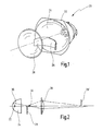
- the PES headlight 20 consists of a poly-ellipsoidal reflector 24, a light source 22, such as in the form of a halogen lamp from an aperture 26 and a lens 28.
- the aperture 26 is in Beam path between the light source 22 and the lens 28 is arranged.
- the commonly used aperture 26 shade the lower half of the beam, leaving the spotlight after exiting behind the lens 28 substantially directed downwards.
- the beam path of a PES headlight is shown in FIG.
- a lamp 22 is arranged in a first focal point 30 of the reflector 24 in a first focal point 30 of the reflector 24 . Due to the ellipsoidal shape of the reflector 24, the light is focused in a second focus 32, which lies just behind the aperture 26. After that happen the individual light rays the lens 28 and produce a Figure 26 'of the aperture 26 approximately at a distance of approx. 10 m.
- a headlamp To the light distribution of such a PES headlight a set of legal requirements. Also the Headlight manufacturers have their own specifications in order to statutory requirements or the specifications of vehicle manufacturers fulfill.
- the different zones and reference lighting points, which is illuminated by a vertical panel Such a headlamp are shown in Fig. 3.
- the line V-V denotes the vertical center line and H-H the horizontal centerline.
- the individual reference points are drawn in circles.
- HV value An important value for the evaluation of a PES headlamp is in particular the HV value.
- HV point 1 is the HV point 1 ⁇ 25 cm above the illuminated area in 25 m behind the lens. In the horizontal direction is the HV point just above the level of the cut-off through the gradation of the edge of the aperture 26 is generated.
- the illuminance at the HV point must be ⁇ 1 lux, preferably even lower.
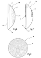
- a lens according to the invention, with all the required specifications are to be observed is shown in Fig. 4 and in total designated by the numeral 28.
- the lens 28 is a plano-convex lens, which is convex on its first surface 34 and on the second opposite surface 36 approximately plan is trained.
- the lens 28 has a circumferential fastening edge 38, which is no longer the optically effective surface belongs.
- the lens 28 is preferably made of glass, through Hot pressing was made, for example, from the glass B270 (according to Schott specification).
- the lens 28 now has, on its convex side, ie on its first surface 34, an edge region 40 which extends annularly inwards from the outer circumference D and to which a second region 42 adjoins which has an increased optical scattering effect or has increased surface roughness. While the edge region 40 is smooth, that is to say optically bare, the region 42 has an increased surface roughness with an average roughness depth r m of at most 10 micrometers, which is preferably of the order of magnitude between approximately 3 and 5 micrometers. In contrast, the smooth edge region 40 has a roughness depth that is more than an order of magnitude lower, for example in the range of about 400 nm.
- the edge region 40 has a diameter d, which extends over a range of D ⁇ d ⁇ 0.65 D extends, preferably via a range D ⁇ d ⁇ 0.75 D, more preferably over a range of about D ⁇ d ⁇ 0.8 D, where D is the outside diameter of the optically effective range.
- D is the outside diameter of the optically effective range.
- a suitable glass for example B270
- a melting furnace which takes place at a viscosity in the range from about 10 3 to about 10 4 poise. In the case of the glass mentioned, this can be carried out at a temperature of approximately 1110.degree.
- a portioning of individual amounts of glass which are suitable for a subsequent hot pressing process for lens production takes place.
- Such portioned glass masses are referred to as so-called "gobs".
- the portioning to produce a gobs is preferably carried out by means of a glass shear on a suitable outlet from the melting tank.
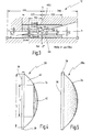
- the gob now reaches a gas bed or a levitation mold 52 according to FIGS.
- the gob 58 On which the gob 58 is held in suspension by gas flowing out of gas nozzles 54. Due to the effective gravitational forces and its relatively low viscosity, the gob assumes an approximate lens shape, as indicated in FIG.
- the gas exiting via the gas nozzles 54 is supplied via a feed channel 56 from below into the levitation mold 52.
- the supplied gas may be air or a protective gas such as nitrogen.
- the Gob 58 is then in a Press mold transferred, in Fig. 11 in total with the numeral 60th is indicated.
- the mold 60 has a first mold half 62, in which with a first Form surface 64 of the convex part of the lens 28 to be pressed is formed is.
- a second mold half 66 has a second mold surface 68, by means of which the flat side of the lens 28 is generated becomes. Also, in the above-arranged second mold half 66 a central channel 70 is provided, via which a vent can be done.
- the first mold surface 64 is now suitably configured, so that the produced in the hot pressing process Lens 28 on its convex side, the smooth edge portion 40 and the central region 42 with increased optical scattering effect receives.
- the molding surface 64 can thus be surface-treated in a suitable manner be roughened and at the predetermined location so as not to require later treatment Surface roughness or optical scattering effect on the finished To produce lens at the desired geometric location.
- the two Mold halves 62, 66 are formed by suitable methods, such as Turning, milling, EDM, laser machining etc. edited.
- the areas where the lens surface is smooth be polished or sanded if necessary to to achieve the desired surface roughness. Too smooth Surface must also be avoided, otherwise it during the hot pressing process would come to a sticking to the mold.
- the areas with increased surface roughness can be about by a blasting process (e.g., glass-blasting) through EDM process, by means of laser processing or in other Be generated manner.
- a suitable viscosity for the subsequent hot pressing process is set, which is approximately at 10 3.3 poise, which is a temperature when using the glass B270 from about 950 to 1000 ° C corresponds.
- the subsequent hot pressing operation is carried out in a viscosity range of about 10 8 to 10 12 poise, for example at about 10 9.6 poise in the case of the glass B270.
- FIG. 5 A modification of a lens according to the invention is shown in FIG. 5 represented and designated overall by the numeral 28a.
- the smooth edge region 40 clear from the central area 42 with increased optical Scattering or surface roughness is delimited (where however, the transition is as steady as possible to diffraction phenomena to avoid), has the lens shown in Fig. 5 28a a continuously graded surface 34.
- the optical Scattering increases steadily from the outer edge Center of the lens 28a towards.
- FIG Fig. 6 A further modification of a lens according to the invention is shown in FIG Fig. 6 shown and indicated generally by the numeral 28b.
- a smooth edge area 40 provided by an area 42 with increased followed by optical scattering or surface roughness.
- the surface roughness decreases larger diameter towards the middle.
- a small central area 44 of the lens 28b on the convex side smooth is a small central area 44 of the lens 28b on the convex side smooth.
- the lens 28b as shown in FIG. 6 approximately on her plan side be provided with a diffractive element 46.
- a diffractive element 46 This may be, for example, a film that on the plane side is glued.
- certain properties of the lens 28b favorably influenced by the diffraction effects. So can For example, a color fringe caused by the color dispersion of Lens is created to be reduced by a diffractive element.
- Fig. 7 is another variant of an inventive Lens shown and indicated generally by the numeral 28c.
- a smooth edge area provided on the convex side of the lens 28c turn a smooth edge area provided on the convex side of the lens 28c turn a smooth edge area provided.
- a diffractive element 46 the on the flat side of the lens 28c is applied, only in the upper one Half of the lens 28c provided. It may be, for example, here around concentrically arranged diffraction structures act.
- a nose 48 for positioning formed.
- the lens according to the invention additionally approximately at its convex Side with a ring structure 50 may be provided.
- a ring structure 50 may be provided.
- it can be about concentric rings at a distance of 1 mm act, with a depth in the range of about 1 to 10 microns. This steady transitions are guaranteed, such as Training as a sine wave.
- Such a ring structure 50 has virtually no visual impact and will only partially from the automotive industry from a design point of view required.
- the lens according to the invention in principle also from a suitable plastic by means of a press or Embossing process (preferably UV and hot stamping process) produced could be.
- a suitable plastic by means of a press or Embossing process (preferably UV and hot stamping process) produced could be.
- the plastics become to it transparent and long-term stable plastics preferred. Suitable are, for example, polymethylmethacrylimide (PMMI), the has a high temperature resistance, or cycloolefin copolymers (COC) or cycloolefin polymers (COP), the practically no water intake.
- PMMI polymethylmethacrylimide
- COC cycloolefin copolymers
- COP cycloolefin polymers
Landscapes
- Engineering & Computer Science (AREA)
- Chemical & Material Sciences (AREA)
- Materials Engineering (AREA)
- Organic Chemistry (AREA)
- General Engineering & Computer Science (AREA)
- Manufacturing & Machinery (AREA)
- Physics & Mathematics (AREA)
- Microelectronics & Electronic Packaging (AREA)
- Optics & Photonics (AREA)
- Mechanical Engineering (AREA)
- Non-Portable Lighting Devices Or Systems Thereof (AREA)
- Eyeglasses (AREA)
- Casting Or Compression Moulding Of Plastics Or The Like (AREA)
Abstract
Description
- Schmelzen eines Glases,
- Portionieren eines Gobs aus der Schmelze, Einstellen der Temperatur auf eine zum Heißpressen des Gobs geeignete Viskosität,
- Bereitstellen einer Form mit einer ersten Formfläche und mindestens einer zweiten Formfläche, wobei mindestens an der ersten Formfläche Bereiche mit unterschiedlicher Oberflächenrauigkeit gebildet sind,
- Zuführen des Gobs in die geöffnete Form,
- Heißpressen des Gobs zur Ausformung der Linse,
- Abkühlen der Linse bis auf Raumtemperatur.
- Fig. 1
- eine Explosionsdarstellung einer erfindungsgemäßen Beleuchtungseinrichtung in Form eines PES-Scheinwerfers;
- Fig. 2
- den Strahlengang des Scheinwerfers gemäß Fig. 1;
- Fig. 3
- einen mit Abstand vor der Beleuchtungseinrichtung gemäß Fig. 1 angeordneten Messschirm, aus dem die gemäß den einschlägigen Messvorschriften vorgegebenen Zonen entnehmbar sind;
- Fig. 4
- eine erste Ausführung einer erfindungsgemäßen Linse in der Seitenansicht;
- Fig. 5
- eine erste Abwandlung der Linse gemäß Fig. 4;
- Fig. 6
- eine zweite Abwandlung der Linse gemäß Fig. 4;
- Fig. 7
- eine dritte Abwandlung der Linse gemäß Fig. 4;
- Fig. 8
- eine Aufsicht auf die Linse gemäß Fig. 4 in schematischer Darstellung, in der zusätzliche ringförmige Strukturen erkennbar sind;
- Fig. 9
- eine Aufsicht auf eine Levitationsform im Zuge der Linsenherstellung zur Unterstützung eines Gobs auf einem Gasschleier;
- Fig. 10
- eine Seitenansicht der Levitationsform gemäß Fig. 9 nebst einem darüber durch einen Gasfluss in der Schwebe gehaltenen Gob; und
- Fig. 11
- eine schematische Schnittdarstellung einer Form zur Herstellung einer erfindungsgemäßen Linse durch Heißpressen.
Claims (24)
- Linse für Beleuchtungszwecke, insbesondere Linse (28, 28a, 28b, 28c) für einen Scheinwerfer (20) zur Abbildung des von einer Lichtquelle (22) ausgesandten und einem Reflektor (24) reflektierten Lichtes zur Erzeugung eines vorgegebenen Beleuchtungsmusters (12), mit zwei einander gegenüberliegenden Oberflächen (34, 36), dadurch gekennzeichnet, dass an mindestens einer ersten Oberfläche (34) Bereiche (40, 42, 44) mit unterschiedlicher optischer Streuwirkung vorgesehen sind.
- Linse nach Anspruch 1, dadurch gekennzeichnet, dass die Bereiche (40, 42, 44) mit unterschiedlicher optischer Streuwirkung als durch einen Heißpressvorgang von einer Form (60) auf die erste Oberfläche (34) übertragene Bereiche ausgebildet sind.
- Linse nach Anspruch 1 oder 2, dadurch gekennzeichnet, dass die erste Oberfläche (34) einen Randbereich (40) mit einer ersten optischen Streuwirkung und einen sich daran zur Mitte hin anschließenden Bereich (42) mit einer optischen Streuwirkung aufweist, die größer als die erste optische Streuwirkung ist.
- Linse nach Anspruch 3, dadurch gekennzeichnet, dass die Linse (28, 28b, 28c) im Randbereich (40) optisch blank ist.
- Linse nach Anspruch 3 oder 4, dadurch gekennzeichnet, dass der Randbereich (40) einen Durchmesser d aufweist, der sich über einen Bereich von D ≤ d ≤ 0,65 D erstreckt, vorzugsweise über einen Bereich D ≤ d ≤ 0,75 D erstreckt, besonders bevorzugt über einen Bereich von etwa D ≤ d ≤ 0,8 D erstreckt, wobei D der optisch wirksame Außendurchmesser der Linse (28, 28a, 28b, 28c) ist.
- Linse nach einem der vorhergehenden Ansprüche, dadurch gekennzeichnet, dass die optische Streuwirkung zumindest über einen Teilbereich der ersten Oberfläche (34) vom Rand zur Mitte hin zunimmt.
- Linse nach einem der vorhergehenden Ansprüche, dadurch gekennzeichnet, dass auf der ersten Oberfläche ein zentraler Bereich (44) mit geringerer optischer Streuwirkung als ein sich daran nach außen hin anschließender Bereich (42) vorgesehen ist.
- Linse nach einem der vorhergehenden Ansprüche, dadurch gekennzeichnet, dass die Bereiche (42) mit höherer optischer Streuwirkung eine mittlere Rauhtiefe rm von höchstens 10 Mikrometer aufweisen, während die Bereiche (40) mit geringerer optischer Streuwirkung eine mittlere Rauhtiefe von höchstens 1 Mikrometer aufweisen.
- Linse nach einem der vorhergehenden Ansprüche, dadurch gekennzeichnet, dass die erste Oberfläche (34) der Linse (28, 28a, 28b, 28c) konvex ausgebildet ist und die zweite Oberfläche (36) der Linse (28, 28a, 28b, 28c) annähernd plan ausgebildet ist.
- Linse nach einem der vorhergehenden Ansprüche, dadurch gekennzeichnet, dass die Linse (28, 28a, 28b) rotationssymmetrisch ausgebildet ist.
- Linse nach einem der Ansprüche 1 bis 9, dadurch gekennzeichnet, dass die Linse einen Befestigungsrand (38, 48) aufweist, der einen Einbau in einer vorgegebenen Lage in einen Scheinwerfer (20) erlaubt, und dass ein oberer Bereich (42) auf der ersten Oberfläche (34) eine von einem darunter liegenden unteren Bereich abweichende optische Streuwirkung oder Krümmung aufweist.
- Linse nach einem der vorhergehenden Ansprüche, dadurch gekennzeichnet, dass an zumindest einer der beiden Oberflächen (34, 36) eine diffraktive Struktur (46) vorgesehen ist.
- Linse nach Anspruch 12, dadurch gekennzeichnet, dass die diffraktive Struktur (46) auf der zweiten Oberfläche (36) der Linse (28b, 28c) angeordnet ist.
- Linse nach Anspruch 13, dadurch gekennzeichnet, dass die diffraktive Struktur als mit einer der Oberflächen (36) der Linse (28b, 28c) verbundenes Element, vorzugsweise in Form einer Folie oder dergleichen, ausgebildet ist.
- Beleuchtungseinrichtung (20), insbesondere Scheinwerfer für den Kfz-Bereich, mit einer Lichtquelle (22), einem Reflektor (24) und einer Linse (28, 28a, 28b, 28c) nach einem der vorhergehenden Ansprüche und einer zwischen Lichtquelle (22) und Reflektor (24) angeordneten Blende (26).
- Beleuchtungseinrichtung, insbesondere Scheinwerfer, mit einer Lichtquelle, die mindestens eine gerichtet abstrahlende LED aufweist, mit einer Linse nach einem der Ansprüche 1 bis 14 und einer zwischen Lichtquelle und Linse angeordneten Blende.
- Verfahren zur Herstellung einer Linse mit folgenden Schritten:Schmelzen eines Glases,Portionieren eines Gobs (58) aus der Schmelze,Einstellen der Temperatur auf eine zum Heißpressen des Gobs (58) geeignete Viskosität,Bereitstellen einer Form (60) mit einer ersten Formfläche (64) und mindestens einer zweiten Formfläche (68), wobei mindestens an der ersten Formfläche (64) Bereiche mit unterschiedlicher Oberflächenrauigkeit gebildet sind,Zuführen des Gobs (58) in die geöffnete Form (60),Heißpressen des Gobs (58) zur Ausformung der Linse,Abkühlen der Linse bis auf Raumtemperatur.
- Verfahren nach Anspruch 17, bei dem eine Form verwendet wird, bei der die erste Formfläche (64) einen Randbereich (40) mit einer ersten zum Blankpressen geeigneten Oberflächenrauigkeit aufweist, an die sich zur Mitte der Form hin ein Bereich (42) mit höherer Oberflächenrauigkeit anschließt.
- Verfahren nach Anspruch 17 oder 18, bei dem eine Form verwendet wird, bei der die erste Formfläche (64) eine Oberflächenrauigkeit aufweist, die zumindest über einen Teilbereich vom Rand zur Mitte hin zunimmt.
- Verfahren nach einem der Ansprüche 17 bis 19, bei dem eine Form (60) verwendet wird, bei der die Bereiche der ersten Formfläche (64) mit unterschiedlicher Oberflächenrauigkeit derart ausgebildet sind, dass beim Heißpressen der Linse (28, 28a, 28b, 28c) an der von der ersten Formfläche (64) abgeformten ersten Oberfläche der Linse Bereiche mit höherer Oberflächenrauigkeit mit einer mittleren Rauhtiefe rm von höchsten 10 Mikrometer ausgebildet werden.
- Verfahren nach einem der Ansprüche 17 bis 20, bei dem die Bereiche (40) mit niedrigerer Oberflächenrauigkeit zum Blankpressen der Linse verwendet werden.
- Verfahren nach einem der Ansprüche 17 bis 21, bei dem eine Form (60) verwendet wird, deren erste Formfläche (64) konvex ausgebildet ist, während die zweite Formfläche (68) annähernd plan ausgebildet ist.
- Verfahren nach einem der Ansprüche 17 bis 22, bei dem die Linse (28, 28a, 28b, 28c) innerhalb der Form (60) während des Heißpressvorgangs zumindest an einer ihrer Außenoberflächen bis auf eine Temperatur unterhalb der Glastransformationstemperatur Tg abgekühlt wird.
- Form zum Heißpressen einer Linse (28, 28a, 28b, 28c) mit einer ersten Formfläche (64) und mindestens einer zweiten Formfläche (68), wobei mindestens an der ersten Formfläche (64) Bereiche mit unterschiedlicher Oberflächenrauigkeit gebildet sind.
Applications Claiming Priority (2)
| Application Number | Priority Date | Filing Date | Title |
|---|---|---|---|
| DE102004018424.0A DE102004018424B4 (de) | 2004-04-08 | 2004-04-08 | Verfahren zur Herstellung einer Linse |
| DE102004018424 | 2004-04-08 |
Publications (3)
| Publication Number | Publication Date |
|---|---|
| EP1584863A2 true EP1584863A2 (de) | 2005-10-12 |
| EP1584863A3 EP1584863A3 (de) | 2006-12-06 |
| EP1584863B1 EP1584863B1 (de) | 2008-11-12 |
Family
ID=34895585
Family Applications (1)
| Application Number | Title | Priority Date | Filing Date |
|---|---|---|---|
| EP05006901A Expired - Lifetime EP1584863B1 (de) | 2004-04-08 | 2005-03-30 | Beleuchtungseinrichtung mit Linse und Herstellverfahren für eine solche |
Country Status (7)
| Country | Link |
|---|---|
| US (2) | US20050254254A1 (de) |
| EP (1) | EP1584863B1 (de) |
| JP (1) | JP2005302718A (de) |
| KR (1) | KR101009880B1 (de) |
| CN (1) | CN1680748A (de) |
| AT (1) | ATE414239T1 (de) |
| DE (2) | DE102004018424B4 (de) |
Cited By (11)
| Publication number | Priority date | Publication date | Assignee | Title |
|---|---|---|---|---|
| WO2007121695A1 (de) * | 2006-04-24 | 2007-11-01 | Docter Optics Gmbh | Scheinwerferlinse für einen kraftfahrzeugscheinwerfer |
| WO2008074304A1 (de) * | 2006-12-18 | 2008-06-26 | Docter Optics Gmbh | Herstellungsverfahren für eine scheinwerferlinse und scheinwerferlinse für einen kraftfahrzeugscheinwerfer |
| DE102007035025A1 (de) * | 2007-07-26 | 2009-01-29 | Docter Optics Gmbh | Verfahren zum Herstellen einer Scheinwerferlinse für einen Kraftfahrzeugscheinwerfer |
| DE102007037204A1 (de) * | 2007-08-07 | 2009-02-26 | Docter Optics Gmbh | Verfahren zum Herstellen eines optischen Linsenelementes, insbesondere einer Scheinwerferlinse für einen Kraftfahrzeugscheinwerfer |
| DE102007044517A1 (de) | 2007-09-18 | 2009-03-19 | Docter Optics Gmbh | Verfahren zum Herstellen einer Scheinwerferlinse für einen Fahrzeugscheinwerfer |
| WO2010054956A1 (de) * | 2008-11-14 | 2010-05-20 | Osram Gesellschaft mit beschränkter Haftung | Optische linse für eine beleuchtungseinheit und beleuchtungseinheit sowie fahrzeugscheinwerfer |
| CN101570155B (zh) * | 2008-05-04 | 2012-03-28 | 法雷奥视觉公司 | 用于机动车的双功能头灯 |
| WO2012146328A1 (de) * | 2011-04-29 | 2012-11-01 | Docter Optics Gmbh | Verfahren zum herstellen eines optischen linsenelementes, insbesondere einer scheinwerferlinse für einen kraftfahrzeugscheinwerfer |
| US8556482B2 (en) | 2007-07-26 | 2013-10-15 | Docter Optics Se | Method for producing a headlamp lens for a motor-vehicle headlamp |
| EP2924339A4 (de) * | 2012-11-20 | 2016-08-10 | Ichikoh Industries Ltd | Fahrzeugscheinwerfer |
| EP3379143A1 (de) * | 2017-03-21 | 2018-09-26 | Valeo Vision | Leuchtmodul mit korrektur der chromatischen abräsion |
Families Citing this family (50)
| Publication number | Priority date | Publication date | Assignee | Title |
|---|---|---|---|---|
| US20070162091A1 (en) * | 2006-01-06 | 2007-07-12 | Hodge Colin G | Phototherapy light with fresnel lens for infant care apparatus |
| US7563008B2 (en) * | 2006-03-28 | 2009-07-21 | Visteon Global Technologies, Inc. | LED projector headlamps using single or multi-faceted lenses |
| JP4597890B2 (ja) | 2006-03-29 | 2010-12-15 | 株式会社小糸製作所 | 車両用前照灯の灯具ユニット |
| US7390113B2 (en) * | 2006-04-20 | 2008-06-24 | Chungchou Institute Of Technology | Projector-type vehicle headlamp system |
| JP2008153176A (ja) * | 2006-12-20 | 2008-07-03 | Ichikoh Ind Ltd | 車両用ヘッドランプ |
| KR101274448B1 (ko) * | 2007-07-10 | 2013-06-18 | 현대자동차주식회사 | 차량용 헤드램프 장치 |
| WO2009028686A1 (ja) * | 2007-08-30 | 2009-03-05 | Nalux Co., Ltd. | 車両用灯具 |
| JP5315505B2 (ja) * | 2007-08-30 | 2013-10-16 | ナルックス株式会社 | 車両用灯具及びその製造方法 |
| WO2009028076A1 (ja) | 2007-08-30 | 2009-03-05 | Nalux Co., Ltd. | 車両用灯具 |
| USD611650S1 (en) * | 2008-01-11 | 2010-03-09 | Edroy Participatie B.V. | LED light |
| USD615696S1 (en) * | 2008-02-04 | 2010-05-11 | Electronic Controls Company | Reflector |
| JP4479805B2 (ja) * | 2008-02-15 | 2010-06-09 | ソニー株式会社 | レンズ、光源ユニット、バックライト装置及び表示装置 |
| DE102008012283B3 (de) * | 2008-03-03 | 2009-04-02 | Docter Optics Gmbh | Verfahren zum Herstellen einer Kraftfahrzeugscheinwerferlinse |
| DE102008049860A1 (de) | 2008-10-01 | 2010-04-08 | Docter Optics Gmbh | Verfahren zum Herstellen einer Kraftfahrzeugscheinwerferlinse |
| DE102008023551B4 (de) | 2008-05-14 | 2019-05-09 | Automotive Lighting Reutlingen Gmbh | Beleuchtungseinrichtung in Form eines Projektionsscheinwerfers für Kraftfahrzeuge |
| JP5169732B2 (ja) * | 2008-10-24 | 2013-03-27 | コニカミノルタアドバンストレイヤー株式会社 | ガラス成形体の製造方法及び上型の製造方法 |
| USD604450S1 (en) * | 2008-12-30 | 2009-11-17 | Jacob M Blumer | Light reflector |
| KR101243826B1 (ko) | 2009-02-17 | 2013-03-18 | 엘지디스플레이 주식회사 | Led 패키지 및 그 제조방법과 led 패키지를 갖는 광원 유닛 |
| DE102009017424B4 (de) * | 2009-04-15 | 2014-10-23 | Automotive Lighting Reutlingen Gmbh | Vorsatzoptik für eine Lichtquelle und Beleuchtungseinrichtung für ein Kraftfahrzeug mit einer solchen Vorsatzoptik |
| JP5618721B2 (ja) * | 2010-09-13 | 2014-11-05 | 株式会社小糸製作所 | レンズの製造方法 |
| KR101199109B1 (ko) * | 2010-09-17 | 2012-11-09 | 현대자동차주식회사 | 헤드램프용 비구면렌즈의 태양광 분산구조 |
| JP5719671B2 (ja) * | 2010-11-05 | 2015-05-20 | 株式会社小糸製作所 | 車両用灯具 |
| JP5780840B2 (ja) * | 2011-06-07 | 2015-09-16 | 株式会社小糸製作所 | 車両用灯具 |
| US8573809B2 (en) * | 2011-08-24 | 2013-11-05 | Panasonic Corporation | Illumination device |
| DE102011112285A1 (de) | 2011-09-05 | 2013-03-07 | Schott Ag | Lichtformung mittels LED-Lichtquelle |
| JP5798881B2 (ja) * | 2011-10-24 | 2015-10-21 | スタンレー電気株式会社 | プロジェクタレンズ及びその製造方法並びにこのプロジェクタレンズを用いた自動車用ヘッドランプ |
| JP5950385B2 (ja) * | 2012-01-25 | 2016-07-13 | 株式会社小糸製作所 | 車輌用前照灯 |
| DE102012106289B4 (de) * | 2012-07-12 | 2016-10-27 | Schott Ag | Stablinse und Verfahren zu ihrer Herstellung |
| DE202012102644U1 (de) * | 2012-07-17 | 2013-10-21 | Zumtobel Lighting Gmbh | Lichtabgabeanordnung und Leuchte mit einer Lichtabgabeanordnung |
| DE102012107427A1 (de) * | 2012-08-14 | 2014-05-22 | Hella Kgaa Hueck & Co. | Optische Fläche und Beleuchtungsvorrichtung für Fahrzeuge |
| TWI565443B (zh) * | 2012-10-30 | 2017-01-11 | 鴻海精密工業股份有限公司 | 電子香的製造方法 |
| US10162158B2 (en) * | 2013-11-21 | 2018-12-25 | Koito Manufacturing Co., Ltd. | Projection lens with peripheral thick part and vehicle lamp provided with the same |
| CN103672733A (zh) * | 2013-12-29 | 2014-03-26 | 哈尔滨固泰电子有限责任公司 | 消除色散的led汽车前雾透镜及消除色散的方法 |
| JP6299265B2 (ja) * | 2014-02-19 | 2018-03-28 | 市光工業株式会社 | 車両用前照灯 |
| JP6663164B2 (ja) | 2014-02-24 | 2020-03-11 | 株式会社小糸製作所 | 車両用灯具ユニット |
| TWI585340B (zh) * | 2014-04-16 | 2017-06-01 | 鴻海精密工業股份有限公司 | 點光源的擴散鏡片 |
| KR20170034392A (ko) * | 2014-07-23 | 2017-03-28 | 미오텍 퍼시픽 코포레이션 | 안개등 렌즈 및 조립체 |
| CN105333369B (zh) * | 2014-07-24 | 2019-08-09 | 市光法雷奥(佛山)汽车照明系统有限公司 | 用于机动车辆的牌照灯以及包含该牌照灯的机动车辆 |
| DE102014118745B4 (de) * | 2014-12-16 | 2022-03-17 | HELLA GmbH & Co. KGaA | Scheinwerfer für Fahrzeuge |
| DE102015202515A1 (de) * | 2015-02-12 | 2016-08-18 | Zumtobel Lighting Gmbh | Optisches Element zur Beeinflussung der Lichtabgabe von Leuchtmitteln |
| DE102015204665A1 (de) * | 2015-03-16 | 2016-09-22 | Zumtobel Lighting Gmbh | Optisches Element zur Beeinflussung der Lichtabgabe von Leuchtmitteln |
| DE102015204690A1 (de) * | 2015-03-16 | 2016-09-22 | Zumtobel Lighting Gmbh | Optisches Element zur Beeinflussung der Lichtabgabe von Leuchtmitteln |
| JP2017120745A (ja) * | 2015-12-28 | 2017-07-06 | パナソニックIpマネジメント株式会社 | 照明装置及び自動車 |
| JP6733464B2 (ja) * | 2016-09-28 | 2020-07-29 | 信越化学工業株式会社 | ハーフトーン位相シフトマスクブランク及びハーフトーン位相シフトマスク |
| AT520488B1 (de) * | 2017-10-04 | 2019-07-15 | Zkw Group Gmbh | Fahrzeugscheinwerfer |
| DE102017130937B3 (de) | 2017-12-21 | 2019-05-09 | Automotive Lighting Reutlingen Gmbh | Lichtmodul eines Kraftfahrzeugscheinwerfers, Scheinwerfer mit einem solchen Lichtmodul und Scheinwerferanordnung mit zwei solchen Scheinwerfern |
| US10627553B2 (en) * | 2018-01-15 | 2020-04-21 | Ford Global Technologies, Llc | Vehicle light assemblies |
| DE102018105958B4 (de) | 2018-03-15 | 2023-10-26 | HELLA GmbH & Co. KGaA | Verfahren zur Herstellung eines Werkzeugs für die Herstellung mikrostrukturier-ter optischer Bauteile und Werkzeug für die Herstellung mikrostrukturierter op-tischer Bauteile |
| US12221372B2 (en) * | 2022-08-18 | 2025-02-11 | AAC Optics (Chongqing) Co., Ltd. | Mold for molding glass product |
| CN118295190A (zh) * | 2023-01-03 | 2024-07-05 | 中强光电股份有限公司 | 光调节模块 |
Family Cites Families (45)
| Publication number | Priority date | Publication date | Assignee | Title |
|---|---|---|---|---|
| US1213154A (en) * | 1916-07-27 | 1917-01-23 | Henry D Cohen | Automobile-headlight glass. |
| US1397822A (en) * | 1920-10-14 | 1921-11-22 | Chauncey G Peters | Headlight diffraction-lens |
| US1561149A (en) * | 1923-02-09 | 1925-11-10 | Frederick Franklin Burya | Light-projecting lens |
| US2220145A (en) * | 1938-07-26 | 1940-11-05 | Cooke Hereward Lester | Headlight |
| US2463280A (en) * | 1943-02-16 | 1949-03-01 | Frank J Kaehni | Spectroscope grating having spaced zones of diffraction lines |
| US2512623A (en) * | 1944-06-27 | 1950-06-27 | Bristol Steel & Iron Works Inc | Headlight lens |
| US2855500A (en) * | 1954-07-09 | 1958-10-07 | John A Holman | Glare filter for head lamp |
| US2867718A (en) * | 1956-10-01 | 1959-01-06 | James B Anderson | Glare reducing shield |
| US3703636A (en) * | 1971-04-07 | 1972-11-21 | Roman A Schmitt | Anti-fog headlight with opaque mask |
| US4020338A (en) * | 1975-06-16 | 1977-04-26 | Auto Gard, Inc. | Auto headlight lens shield |
| US4209825A (en) * | 1977-12-27 | 1980-06-24 | Optronics, Inc. | Lamp |
| US4473872A (en) * | 1982-05-21 | 1984-09-25 | Gte Products Corporation | Par spot lamp |
| USD284792S (en) * | 1983-08-18 | 1986-07-22 | Gte Products Corporation | Spot lamp |
| FR2550847B1 (fr) * | 1983-08-18 | 1988-07-01 | Cibie Projecteurs | Projecteur a reflecteur elliptique et a faisceau coupe, pour vehicule automobile |
| HU191446B (en) * | 1984-09-21 | 1987-02-27 | Tungsram Rt,Hu | Reflector lamp |
| DE3602262C2 (de) * | 1985-11-07 | 1995-05-11 | Bosch Gmbh Robert | Refraktorelement für einen Kraftfahrzeugscheinwerfer für Abblendlicht oder Nebellicht |
| EP0221416B1 (de) * | 1985-11-07 | 1995-09-27 | Robert Bosch Gmbh | Scheinwerfer für Abblendlicht oder Nebellicht von Kraftfahrzeugen |
| USD301069S (en) * | 1985-12-19 | 1989-05-09 | Gte Products Corporation | Reflector-type electric lamp or the like |
| US4740875A (en) * | 1987-05-07 | 1988-04-26 | Gte Products Corporation | Motor vehicle headlight having lens with glare prevention means |
| USD321762S (en) * | 1989-02-17 | 1991-11-19 | North American Philips Corporation | Reflector spot lamp |
| JP2754690B2 (ja) * | 1989-03-31 | 1998-05-20 | 市光工業株式会社 | プロジェクタ型前照灯 |
| JPH0817045B2 (ja) * | 1989-10-06 | 1996-02-21 | 株式会社小糸製作所 | 自動車用ヘッドランプ |
| DE4031351C2 (de) * | 1990-10-04 | 2000-07-06 | Bosch Gmbh Robert | Projektionslinse als Bestandteil eines Kraftfahrzeugscheinwerfers für Abblendlicht oder Nebellicht |
| JP3164404B2 (ja) * | 1992-02-21 | 2001-05-08 | オリンパス光学工業株式会社 | ガラス光学素子の成形装置と成形方法 |
| IN179055B (de) * | 1992-04-15 | 1997-08-16 | Optical & Textile Ltd | |
| DE4215584C2 (de) * | 1992-05-12 | 2002-06-20 | Bosch Gmbh Robert | Beleuchtungseinrichtung mit einem Reflektor und mit optisch wirksamen Elementen |
| IT1261250B (it) * | 1993-09-03 | 1996-05-09 | Carello Spa | Dispositivo di illuminazione in particolare per autoveicoli |
| JP3974200B2 (ja) * | 1995-11-09 | 2007-09-12 | Hoya株式会社 | ガラス光学素子の成形方法 |
| USD379538S (en) * | 1996-05-14 | 1997-05-27 | Osram Sylvania Inc. | Electric par lamp |
| JP3361228B2 (ja) * | 1996-06-04 | 2003-01-07 | 富士写真光機株式会社 | 光学部品製造方法 |
| DE19633164C2 (de) * | 1996-08-17 | 2000-02-24 | Docter Optics Gmbh | Verfahren und Vorrichtung zum Blankpressen von optischen Bauteilen |
| WO1999000623A1 (en) * | 1997-06-30 | 1999-01-07 | Donnelly Corporation | Automotive lamp lens and lamp system utilizing diffractive optics and method for making the same |
| US5921572A (en) | 1997-07-31 | 1999-07-13 | Outback Bicycles, Inc. | Continuously compensating bicycle suspension system |
| DE19814480B4 (de) * | 1998-04-01 | 2006-07-20 | Automotive Lighting Reutlingen Gmbh | Scheinwerfer für Fahrzeuge nach dem Projektionsprinzip |
| DE19830298C2 (de) * | 1998-07-07 | 2002-06-27 | Bosch Gmbh Robert | Kraftfahrzeugscheinwerfer mit verstellbarer Abschirmvorrichtung |
| US6105220A (en) * | 1999-02-11 | 2000-08-22 | Cercueils Alliance Caskets Inc. | Structure for a casket shell |
| JP3922834B2 (ja) * | 1999-06-24 | 2007-05-30 | Hoya株式会社 | ガラス光学素子用成形型及び該成形型を用いたガラス光学素子の製造方法 |
| JP3886672B2 (ja) * | 1999-07-12 | 2007-02-28 | 株式会社小糸製作所 | 車両用前照灯 |
| US6480344B1 (en) * | 1999-11-22 | 2002-11-12 | Asahi Kogaku Kogyo Kabushiki Kaisha | Objective lens for optical pick-up |
| US20020118465A1 (en) * | 2001-02-28 | 2002-08-29 | Konica Corporation | Molding die for optical element, optical element and master die |
| JP4203709B2 (ja) * | 2001-02-28 | 2009-01-07 | コニカミノルタホールディングス株式会社 | 光学素子成形金型 |
| DE10226471B4 (de) * | 2002-06-14 | 2007-03-22 | Schott Ag | Optische Linse mit Weichzeicheneffekt |
| KR100525229B1 (ko) * | 2003-10-13 | 2005-10-28 | 삼성전기주식회사 | Dvd/cd 호환형의 광픽업용 대물렌즈 |
| CA2562438A1 (en) * | 2004-04-08 | 2005-10-27 | Federal-Mogul Corporation | Projector lamp headlight with chromatic aberration correction |
| US7488084B2 (en) * | 2004-10-29 | 2009-02-10 | Pentair Water Pool And Spa, Inc. | Selectable beam lens for underwater light |
-
2004
- 2004-04-08 DE DE102004018424.0A patent/DE102004018424B4/de not_active Expired - Fee Related
-
2005
- 2005-03-30 EP EP05006901A patent/EP1584863B1/de not_active Expired - Lifetime
- 2005-03-30 AT AT05006901T patent/ATE414239T1/de not_active IP Right Cessation
- 2005-03-30 DE DE502005005925T patent/DE502005005925D1/de not_active Expired - Lifetime
- 2005-04-05 JP JP2005108705A patent/JP2005302718A/ja active Pending
- 2005-04-06 US US11/099,973 patent/US20050254254A1/en not_active Abandoned
- 2005-04-08 KR KR1020050029317A patent/KR101009880B1/ko not_active Expired - Fee Related
- 2005-04-08 CN CNA2005100649056A patent/CN1680748A/zh active Pending
-
2010
- 2010-09-23 US US12/888,706 patent/US20110011133A1/en not_active Abandoned
Cited By (24)
| Publication number | Priority date | Publication date | Assignee | Title |
|---|---|---|---|---|
| US7798688B2 (en) | 2006-04-24 | 2010-09-21 | Docter Optics Gmbh | Headlight lens for a motor vehicle |
| DE112007000189B4 (de) * | 2006-04-24 | 2019-03-21 | Docter Optics Se | Scheinwerferlinse für einen Kraftfahrzeugscheinwerfer |
| WO2007121695A1 (de) * | 2006-04-24 | 2007-11-01 | Docter Optics Gmbh | Scheinwerferlinse für einen kraftfahrzeugscheinwerfer |
| US8517582B1 (en) | 2006-12-18 | 2013-08-27 | Docter Optics Se | Production method for a headlight lens and headlight lens for a motor vehicle headlight |
| US8251557B2 (en) | 2006-12-18 | 2012-08-28 | Docter Optics Gmbh | Production method for a headlight lens and headlight lens for a motor vehicle headlight |
| US8414170B2 (en) | 2006-12-18 | 2013-04-09 | Doctor Optics Gmbh | Production method for a headlight lens and headlight lens for a motor vehicle headlight |
| WO2008074304A1 (de) * | 2006-12-18 | 2008-06-26 | Docter Optics Gmbh | Herstellungsverfahren für eine scheinwerferlinse und scheinwerferlinse für einen kraftfahrzeugscheinwerfer |
| US8556482B2 (en) | 2007-07-26 | 2013-10-15 | Docter Optics Se | Method for producing a headlamp lens for a motor-vehicle headlamp |
| DE102007035025A1 (de) * | 2007-07-26 | 2009-01-29 | Docter Optics Gmbh | Verfahren zum Herstellen einer Scheinwerferlinse für einen Kraftfahrzeugscheinwerfer |
| DE102007037204B4 (de) * | 2007-08-07 | 2020-11-12 | Docter Optics Se | Verfahren zum Herstellen eines optischen Linsenelementes, insbesondere einer Scheinwerferlinse für einen Kraftfahrzeugscheinwerfer sowie Charge von hintereinander hergestellten Scheinwerferlinsen |
| DE102007037204A1 (de) * | 2007-08-07 | 2009-02-26 | Docter Optics Gmbh | Verfahren zum Herstellen eines optischen Linsenelementes, insbesondere einer Scheinwerferlinse für einen Kraftfahrzeugscheinwerfer |
| US9421706B2 (en) | 2007-08-07 | 2016-08-23 | Docter Optics Gmbh | Method for producing an optical lens element, particularly a headlight lens for a motor vehicle headlight |
| DE112008003157B4 (de) * | 2007-09-18 | 2012-01-19 | Docter Optics Gmbh | Verfahren zum Herstellen einer Scheinwerferlinse für einen Fahrzeugscheinwerfer |
| DE102007044517A1 (de) | 2007-09-18 | 2009-03-19 | Docter Optics Gmbh | Verfahren zum Herstellen einer Scheinwerferlinse für einen Fahrzeugscheinwerfer |
| CN101570155B (zh) * | 2008-05-04 | 2012-03-28 | 法雷奥视觉公司 | 用于机动车的双功能头灯 |
| WO2010054956A1 (de) * | 2008-11-14 | 2010-05-20 | Osram Gesellschaft mit beschränkter Haftung | Optische linse für eine beleuchtungseinheit und beleuchtungseinheit sowie fahrzeugscheinwerfer |
| DE102008057353B4 (de) | 2008-11-14 | 2020-06-10 | Osram Gmbh | Optische Linse für eine Beleuchtungseinheit und Beleuchtungseinheit sowie Fahrzeugscheinwerfer |
| US9358706B2 (en) | 2011-04-29 | 2016-06-07 | Docter Optics Se | Process for manufacturing a headlight lens for a motor vehicle headlight |
| WO2012146328A1 (de) * | 2011-04-29 | 2012-11-01 | Docter Optics Gmbh | Verfahren zum herstellen eines optischen linsenelementes, insbesondere einer scheinwerferlinse für einen kraftfahrzeugscheinwerfer |
| US9476559B2 (en) | 2012-11-20 | 2016-10-25 | Ichikoh Industries, Ltd. | Vehicle headlamp |
| EP2924339A4 (de) * | 2012-11-20 | 2016-08-10 | Ichikoh Industries Ltd | Fahrzeugscheinwerfer |
| EP3379143A1 (de) * | 2017-03-21 | 2018-09-26 | Valeo Vision | Leuchtmodul mit korrektur der chromatischen abräsion |
| FR3064339A1 (fr) * | 2017-03-21 | 2018-09-28 | Valeo Vision | Module lumineux avec correction de chromatisme |
| US10415784B2 (en) | 2017-03-21 | 2019-09-17 | Valeo Vision | Lighting module with chromatism correction |
Also Published As
| Publication number | Publication date |
|---|---|
| KR20060046628A (ko) | 2006-05-17 |
| EP1584863B1 (de) | 2008-11-12 |
| US20110011133A1 (en) | 2011-01-20 |
| DE102004018424A1 (de) | 2005-11-17 |
| JP2005302718A (ja) | 2005-10-27 |
| KR101009880B1 (ko) | 2011-01-19 |
| DE502005005925D1 (de) | 2008-12-24 |
| ATE414239T1 (de) | 2008-11-15 |
| CN1680748A (zh) | 2005-10-12 |
| EP1584863A3 (de) | 2006-12-06 |
| US20050254254A1 (en) | 2005-11-17 |
| DE102004018424B4 (de) | 2016-12-08 |
Similar Documents
| Publication | Publication Date | Title |
|---|---|---|
| DE102004018424B4 (de) | Verfahren zur Herstellung einer Linse | |
| AT517887B1 (de) | Mikroprojektions-Lichtmodul für Fahrzeugscheinwerfer | |
| DE112007002504B4 (de) | Scheinwerferlinse für einen Kraftfahrzeugscheinwerfer | |
| DE202004005936U1 (de) | Beleuchtungseinrichtung | |
| DE112006001850B4 (de) | Scheinwerferlinse für einen Kraftfahrzeugscheinwerfer | |
| DE10333370A1 (de) | Beleuchtungseinrichtung, Linse und Herstellung der Linse | |
| EP2484959B1 (de) | Modular aufgebautes Projektionslichtmodul eines Kraftfahrzeugscheinwerfers | |
| DE102008048379B4 (de) | Verfahren zur Herstellung eines Linsen-Arrays | |
| DE102019213502A1 (de) | Fahrzeugleuchte | |
| EP2885574B1 (de) | Optische fläche und beleuchtungsvorrichtung für fahrzeuge | |
| DE202009009763U1 (de) | Optische LED-Linse und Beleuchtungsvorrichtung derselben | |
| DE102011114636A1 (de) | Anordnung und Dimensionierung von Overhead-Elementen auf einer Projektionslinse eines Kraftfahrzeugscheinwerfers | |
| DE102009020593A1 (de) | Zur Erzeugung einer definierten Overhead-Beleuchtung eingerichteter Fahrzeugscheinwerfer | |
| EP3721133B1 (de) | Projektionseinrichtung für einen kraftfahrzeugscheinwerfer | |
| EP2500630B1 (de) | Transparente Optik bzw. Linse einer KFZ-Beleuchtungseinrichtung | |
| DE102019218776A1 (de) | Leuchte für Fahrzeug | |
| EP3721134B1 (de) | Projektionseinrichtung für einen kraftfahrzeugscheinwerfer | |
| DE102022126304A1 (de) | Fresnelprojektionslinse mit integrierter Funktion zur Bedienung der Overhead-Sign-Werte | |
| DE10231162B4 (de) | Fahrzeugleuchte mit Angabezeichen | |
| EP2372236A1 (de) | Optikelement zur Anordnung in einem Scheinwerfer eines Fahrzeugs | |
| DE102004062913B4 (de) | Beleuchtungseinrichtung mit Linse | |
| DE202016103287U1 (de) | Scheinwerfer für Schienenfahrzeuge | |
| AT519356B1 (de) | Lichtmodul für einen Kraftfahrzeugscheinwerfer | |
| DE102017115564A1 (de) | Fahrzeugbeleuchtungsbaugruppen mit unsichtbaren gerillten bereichen und verfahren zur herstellung derselben | |
| DE102009032455B4 (de) | Projektionsmodul für einen Kraftfahrzeugscheinwerfer mit einer Projektionslinse, deren Axialposition eingestellt werden kann, und Verfahren zur Herstellung des Projektionsmoduls |
Legal Events
| Date | Code | Title | Description |
|---|---|---|---|
| PUAI | Public reference made under article 153(3) epc to a published international application that has entered the european phase |
Free format text: ORIGINAL CODE: 0009012 |
|
| AK | Designated contracting states |
Kind code of ref document: A2 Designated state(s): AT BE BG CH CY CZ DE DK EE ES FI FR GB GR HU IE IS IT LI LT LU MC NL PL PT RO SE SI SK TR |
|
| AX | Request for extension of the european patent |
Extension state: AL BA HR LV MK YU |
|
| RIN1 | Information on inventor provided before grant (corrected) |
Inventor name: EBELING, POLINA Inventor name: KOERNER, STEFFEN Inventor name: PETERS, FRANK Inventor name: BONITZ, RALF Inventor name: LARM, HELMUT Inventor name: MOSELER, DORIS |
|
| PUAL | Search report despatched |
Free format text: ORIGINAL CODE: 0009013 |
|
| AK | Designated contracting states |
Kind code of ref document: A3 Designated state(s): AT BE BG CH CY CZ DE DK EE ES FI FR GB GR HU IE IS IT LI LT LU MC NL PL PT RO SE SI SK TR |
|
| AX | Request for extension of the european patent |
Extension state: AL BA HR LV MK YU |
|
| 17P | Request for examination filed |
Effective date: 20070118 |
|
| 17Q | First examination report despatched |
Effective date: 20070212 |
|
| AKX | Designation fees paid |
Designated state(s): AT BE BG CH CY CZ DE DK EE ES FI FR GB GR HU IE IS IT LI LT LU MC NL PL PT RO SE SI SK TR |
|
| GRAP | Despatch of communication of intention to grant a patent |
Free format text: ORIGINAL CODE: EPIDOSNIGR1 |
|
| GRAS | Grant fee paid |
Free format text: ORIGINAL CODE: EPIDOSNIGR3 |
|
| GRAA | (expected) grant |
Free format text: ORIGINAL CODE: 0009210 |
|
| AK | Designated contracting states |
Kind code of ref document: B1 Designated state(s): AT BE BG CH CY CZ DE DK EE ES FI FR GB GR HU IE IS IT LI LT LU MC NL PL PT RO SE SI SK TR |
|
| REG | Reference to a national code |
Ref country code: GB Ref legal event code: FG4D Free format text: NOT ENGLISH |
|
| REG | Reference to a national code |
Ref country code: CH Ref legal event code: EP |
|
| REG | Reference to a national code |
Ref country code: IE Ref legal event code: FG4D Free format text: LANGUAGE OF EP DOCUMENT: GERMAN |
|
| REF | Corresponds to: |
Ref document number: 502005005925 Country of ref document: DE Date of ref document: 20081224 Kind code of ref document: P |
|
| REG | Reference to a national code |
Ref country code: RO Ref legal event code: EPE |
|
| LTIE | Lt: invalidation of european patent or patent extension |
Effective date: 20081112 |
|
| PG25 | Lapsed in a contracting state [announced via postgrant information from national office to epo] |
Ref country code: LT Free format text: LAPSE BECAUSE OF FAILURE TO SUBMIT A TRANSLATION OF THE DESCRIPTION OR TO PAY THE FEE WITHIN THE PRESCRIBED TIME-LIMIT Effective date: 20081112 Ref country code: ES Free format text: LAPSE BECAUSE OF FAILURE TO SUBMIT A TRANSLATION OF THE DESCRIPTION OR TO PAY THE FEE WITHIN THE PRESCRIBED TIME-LIMIT Effective date: 20090223 |
|
| NLV1 | Nl: lapsed or annulled due to failure to fulfill the requirements of art. 29p and 29m of the patents act | ||
| PG25 | Lapsed in a contracting state [announced via postgrant information from national office to epo] |
Ref country code: PL Free format text: LAPSE BECAUSE OF FAILURE TO SUBMIT A TRANSLATION OF THE DESCRIPTION OR TO PAY THE FEE WITHIN THE PRESCRIBED TIME-LIMIT Effective date: 20081112 Ref country code: NL Free format text: LAPSE BECAUSE OF FAILURE TO SUBMIT A TRANSLATION OF THE DESCRIPTION OR TO PAY THE FEE WITHIN THE PRESCRIBED TIME-LIMIT Effective date: 20081112 Ref country code: SI Free format text: LAPSE BECAUSE OF FAILURE TO SUBMIT A TRANSLATION OF THE DESCRIPTION OR TO PAY THE FEE WITHIN THE PRESCRIBED TIME-LIMIT Effective date: 20081112 Ref country code: IS Free format text: LAPSE BECAUSE OF FAILURE TO SUBMIT A TRANSLATION OF THE DESCRIPTION OR TO PAY THE FEE WITHIN THE PRESCRIBED TIME-LIMIT Effective date: 20090312 Ref country code: FI Free format text: LAPSE BECAUSE OF FAILURE TO SUBMIT A TRANSLATION OF THE DESCRIPTION OR TO PAY THE FEE WITHIN THE PRESCRIBED TIME-LIMIT Effective date: 20081112 |
|
| PG25 | Lapsed in a contracting state [announced via postgrant information from national office to epo] |
Ref country code: EE Free format text: LAPSE BECAUSE OF FAILURE TO SUBMIT A TRANSLATION OF THE DESCRIPTION OR TO PAY THE FEE WITHIN THE PRESCRIBED TIME-LIMIT Effective date: 20081112 Ref country code: BG Free format text: LAPSE BECAUSE OF FAILURE TO SUBMIT A TRANSLATION OF THE DESCRIPTION OR TO PAY THE FEE WITHIN THE PRESCRIBED TIME-LIMIT Effective date: 20090212 Ref country code: DK Free format text: LAPSE BECAUSE OF FAILURE TO SUBMIT A TRANSLATION OF THE DESCRIPTION OR TO PAY THE FEE WITHIN THE PRESCRIBED TIME-LIMIT Effective date: 20081112 |
|
| PG25 | Lapsed in a contracting state [announced via postgrant information from national office to epo] |
Ref country code: PT Free format text: LAPSE BECAUSE OF FAILURE TO SUBMIT A TRANSLATION OF THE DESCRIPTION OR TO PAY THE FEE WITHIN THE PRESCRIBED TIME-LIMIT Effective date: 20090413 Ref country code: SE Free format text: LAPSE BECAUSE OF FAILURE TO SUBMIT A TRANSLATION OF THE DESCRIPTION OR TO PAY THE FEE WITHIN THE PRESCRIBED TIME-LIMIT Effective date: 20090212 |
|
| PLBE | No opposition filed within time limit |
Free format text: ORIGINAL CODE: 0009261 |
|
| STAA | Information on the status of an ep patent application or granted ep patent |
Free format text: STATUS: NO OPPOSITION FILED WITHIN TIME LIMIT |
|
| BERE | Be: lapsed |
Owner name: SCHOTT A.G. Effective date: 20090331 |
|
| PG25 | Lapsed in a contracting state [announced via postgrant information from national office to epo] |
Ref country code: SK Free format text: LAPSE BECAUSE OF FAILURE TO SUBMIT A TRANSLATION OF THE DESCRIPTION OR TO PAY THE FEE WITHIN THE PRESCRIBED TIME-LIMIT Effective date: 20081112 |
|
| 26N | No opposition filed |
Effective date: 20090813 |
|
| PG25 | Lapsed in a contracting state [announced via postgrant information from national office to epo] |
Ref country code: MC Free format text: LAPSE BECAUSE OF NON-PAYMENT OF DUE FEES Effective date: 20090331 |
|
| REG | Reference to a national code |
Ref country code: CH Ref legal event code: PL |
|
| GBPC | Gb: european patent ceased through non-payment of renewal fee |
Effective date: 20090330 |
|
| PG25 | Lapsed in a contracting state [announced via postgrant information from national office to epo] |
Ref country code: CH Free format text: LAPSE BECAUSE OF NON-PAYMENT OF DUE FEES Effective date: 20090331 Ref country code: LI Free format text: LAPSE BECAUSE OF NON-PAYMENT OF DUE FEES Effective date: 20090331 |
|
| PG25 | Lapsed in a contracting state [announced via postgrant information from national office to epo] |
Ref country code: BE Free format text: LAPSE BECAUSE OF NON-PAYMENT OF DUE FEES Effective date: 20090331 |
|
| REG | Reference to a national code |
Ref country code: FR Ref legal event code: TP |
|
| PG25 | Lapsed in a contracting state [announced via postgrant information from national office to epo] |
Ref country code: GB Free format text: LAPSE BECAUSE OF NON-PAYMENT OF DUE FEES Effective date: 20090330 |
|
| PGFP | Annual fee paid to national office [announced via postgrant information from national office to epo] |
Ref country code: IE Payment date: 20100325 Year of fee payment: 6 |
|
| PG25 | Lapsed in a contracting state [announced via postgrant information from national office to epo] |
Ref country code: AT Free format text: LAPSE BECAUSE OF NON-PAYMENT OF DUE FEES Effective date: 20090330 |
|
| PG25 | Lapsed in a contracting state [announced via postgrant information from national office to epo] |
Ref country code: GR Free format text: LAPSE BECAUSE OF FAILURE TO SUBMIT A TRANSLATION OF THE DESCRIPTION OR TO PAY THE FEE WITHIN THE PRESCRIBED TIME-LIMIT Effective date: 20090213 |
|
| PG25 | Lapsed in a contracting state [announced via postgrant information from national office to epo] |
Ref country code: IT Free format text: LAPSE BECAUSE OF FAILURE TO SUBMIT A TRANSLATION OF THE DESCRIPTION OR TO PAY THE FEE WITHIN THE PRESCRIBED TIME-LIMIT Effective date: 20081112 |
|
| PG25 | Lapsed in a contracting state [announced via postgrant information from national office to epo] |
Ref country code: LU Free format text: LAPSE BECAUSE OF NON-PAYMENT OF DUE FEES Effective date: 20090330 |
|
| PGFP | Annual fee paid to national office [announced via postgrant information from national office to epo] |
Ref country code: CZ Payment date: 20110328 Year of fee payment: 7 Ref country code: RO Payment date: 20110301 Year of fee payment: 7 |
|
| PG25 | Lapsed in a contracting state [announced via postgrant information from national office to epo] |
Ref country code: HU Free format text: LAPSE BECAUSE OF FAILURE TO SUBMIT A TRANSLATION OF THE DESCRIPTION OR TO PAY THE FEE WITHIN THE PRESCRIBED TIME-LIMIT Effective date: 20090513 |
|
| PG25 | Lapsed in a contracting state [announced via postgrant information from national office to epo] |
Ref country code: TR Free format text: LAPSE BECAUSE OF FAILURE TO SUBMIT A TRANSLATION OF THE DESCRIPTION OR TO PAY THE FEE WITHIN THE PRESCRIBED TIME-LIMIT Effective date: 20081112 |
|
| PG25 | Lapsed in a contracting state [announced via postgrant information from national office to epo] |
Ref country code: CY Free format text: LAPSE BECAUSE OF FAILURE TO SUBMIT A TRANSLATION OF THE DESCRIPTION OR TO PAY THE FEE WITHIN THE PRESCRIBED TIME-LIMIT Effective date: 20081112 |
|
| REG | Reference to a national code |
Ref country code: IE Ref legal event code: MM4A |
|
| PG25 | Lapsed in a contracting state [announced via postgrant information from national office to epo] |
Ref country code: IE Free format text: LAPSE BECAUSE OF NON-PAYMENT OF DUE FEES Effective date: 20110330 |
|
| REG | Reference to a national code |
Ref country code: DE Ref legal event code: R081 Ref document number: 502005005925 Country of ref document: DE Owner name: DOCTER OPTICS SE, DE Free format text: FORMER OWNER: ZWIESEL KRISTALLGLAS AG, 94227 ZWIESEL, DE Effective date: 20120104 |
|
| PG25 | Lapsed in a contracting state [announced via postgrant information from national office to epo] |
Ref country code: CZ Free format text: LAPSE BECAUSE OF NON-PAYMENT OF DUE FEES Effective date: 20120330 |
|
| PG25 | Lapsed in a contracting state [announced via postgrant information from national office to epo] |
Ref country code: RO Free format text: LAPSE BECAUSE OF NON-PAYMENT OF DUE FEES Effective date: 20120330 |
|
| REG | Reference to a national code |
Ref country code: DE Ref legal event code: R082 Ref document number: 502005005925 Country of ref document: DE Representative=s name: SCHNEIDERS & BEHRENDT RECHTSANWAELTE PATENTANW, DE Effective date: 20130321 Ref country code: DE Ref legal event code: R081 Ref document number: 502005005925 Country of ref document: DE Owner name: DOCTER OPTICS SE, DE Free format text: FORMER OWNER: DOCTER OPTICS GMBH, 07806 NEUSTADT, DE Effective date: 20130321 Ref country code: DE Ref legal event code: R082 Ref document number: 502005005925 Country of ref document: DE Representative=s name: SCHNEIDERS & BEHRENDT PARTMBB, RECHTS- UND PAT, DE Effective date: 20130321 |
|
| PGFP | Annual fee paid to national office [announced via postgrant information from national office to epo] |
Ref country code: FR Payment date: 20140319 Year of fee payment: 10 |
|
| REG | Reference to a national code |
Ref country code: FR Ref legal event code: ST Effective date: 20151130 |
|
| PG25 | Lapsed in a contracting state [announced via postgrant information from national office to epo] |
Ref country code: FR Free format text: LAPSE BECAUSE OF NON-PAYMENT OF DUE FEES Effective date: 20150331 |
|
| PGFP | Annual fee paid to national office [announced via postgrant information from national office to epo] |
Ref country code: DE Payment date: 20220331 Year of fee payment: 18 |
|
| REG | Reference to a national code |
Ref country code: DE Ref legal event code: R119 Ref document number: 502005005925 Country of ref document: DE |
|
| PG25 | Lapsed in a contracting state [announced via postgrant information from national office to epo] |
Ref country code: DE Free format text: LAPSE BECAUSE OF NON-PAYMENT OF DUE FEES Effective date: 20231003 |