EP1584418B1 - Befestigungswerkzeug mit Moduswahlschalter - Google Patents
Befestigungswerkzeug mit Moduswahlschalter Download PDFInfo
- Publication number
- EP1584418B1 EP1584418B1 EP05006843A EP05006843A EP1584418B1 EP 1584418 B1 EP1584418 B1 EP 1584418B1 EP 05006843 A EP05006843 A EP 05006843A EP 05006843 A EP05006843 A EP 05006843A EP 1584418 B1 EP1584418 B1 EP 1584418B1
- Authority
- EP
- European Patent Office
- Prior art keywords
- trigger
- switch
- state
- contact trip
- controller
- Prior art date
- Legal status (The legal status is an assumption and is not a legal conclusion. Google has not performed a legal analysis and makes no representation as to the accuracy of the status listed.)
- Not-in-force
Links
Images


Classifications
-
- B—PERFORMING OPERATIONS; TRANSPORTING
- B25—HAND TOOLS; PORTABLE POWER-DRIVEN TOOLS; MANIPULATORS
- B25C—HAND-HELD NAILING OR STAPLING TOOLS; MANUALLY OPERATED PORTABLE STAPLING TOOLS
- B25C1/00—Hand-held nailing tools; Nail feeding devices
- B25C1/06—Hand-held nailing tools; Nail feeding devices operated by electric power
Definitions
- the present invention generally relates to fastening tools according to the preambles of claims 1, 10, 18 and 23 and more particularly to a control unit for operating a fastening tool and a related methodology, according to the preamble of claim 27.
- Such tools and such a method are known from document WO 02 051 591 A .
- Power nailers are relatively common place in the construction trades. Often times, however, the power nailers that are available may not provide the user with a desired degree of flexibility and freedom due to the presence of hoses and such that couple the power nailer to a source of pneumatic power. Accordingly, there remains a need in the art for an improved power nailer.
- WO02/051591 describes a control module for a flywheel operated hand tool.
- the hand tool can be operated in two modes of operation, a continuous mode in which the flywheel is rotated continuously, and an intermittent mode in which the flywheel is only operated when required by a user.
- the intermittent mode is used for example to conserve battery power.
- the continuous mode the tool can be operated in two ways, firstly in a "trigger fire” mode in which a safety signal (i.e. the user depressing a contact trip) preceeds a trigger signal, and secondly in a "bottom fire” mode in which the trigger signal preceeds the safety signal.
- a fastening tool for installing fasteners into a workpiece comprising:
- a fastening tool for installing fasteners into a workpiece comprising:
- a fastening tool for installing fasteners into a workpiece, the fastening tool comprising:
- a fastening tool comprising:
- the present invention provides a fastening tool for installing fasteners into a workpiece.
- the fastening tool can include a contact trip switch, which is actuated in response to a first operator input, a trigger switch, which is actuated in response to a second operator input, a driver that is movable along an axis, a motor assembly and a controller.
- the motor assembly can have a flywheel, which can be driven by a motor, and an actuator that can be actuated to drive the driver into engagement with the flywheel to cause the driver to move along the axis.
- the controller can be configured to selectively activate the motor assembly to cause the driver to translate along the axis at least partially in response to actuation of the contact trip switch and the trigger switch.
- the controller can include a mode selector switch having a first switch state and a second switch state. Placement of the mode selector switch into the first switch state requires that the contact trip switch be actuated prior to actuation of the trigger switch before the controller actuates the actuator. Placement of the mode selector switch into the second switch state permits the controller to activate the actuator when both the contract trip switch and the trigger switch have been activated regardless of an order in which the contract trip switch and the trigger switch have been activated.
- the present invention provides a fastening tool for installing fasteners into a workpiece.
- the fastening tool can include a nosepiece, a contact trip, a tool body, which can be coupled to the nosepiece, a driver, a motor assembly, a trigger and a controller.
- the contact trip can be coupled to the nosepiece and can be movable between a first contact trip position and a second contact trip position.
- the contact trip can be biased into the first contact trip position and move into the second contact trip position in response to a first operator input.
- the driver can be housed in the tool body and movable along an axis through at least a portion of the nosepiece.
- the motor assembly can be configured to translate the driver along the axis.
- the trigger can be coupled to the tool body and can be movable between a first trigger position and a second trigger position.
- the trigger can be biased into the first trigger position and can move into the second trigger position in response to a second operator input.
- the controller can be configured to selectively activate the motor assembly and can include a mode selector having a first state and a second state. Placement of the mode selector into the first state requires that the contact trip be moved into the second contact trip position prior to movement of the trigger into the second trigger position to actuate the motor assembly and cause the driver to translate along the axis. Placement of the mode selector into the second state permits the controller to activate the motor assembly and cause the driver to translate along the axis regardless of an order in which the contact trip is moved into the second contact trip position and the trigger is moved into the second trigger position.
- the teachings of the present invention provide a method that can include: providing an electric fastening tool having a contact trip, a trigger, a driver that is moveable along an axis, and a mode selector switch, the mode selector switch having a sequential setting and a bump-feed setting; placing the mode selector switch into the bump-feed setting; and operating the tool such that a) the trigger is moved into an actuated state; b) the contact trip is moved into an actuated state after the trigger has been moved into the actuated state; and c) the driver is translated along the axis without first changing the trigger to an unactuated state.
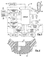
- an electric fastener delivery device which may be referred to herein as a nailer, is generally indicated by reference numeral 10. While the electric fastener delivery device is generally described in terms of a fastening tool 10 that drives nails into a workpiece, the electric fastener delivery device may be configured to deliver different fasteners, such as a staple or screw, or combinations of one or more of the different fasteners. Further, while the fastening tool 10 is generally described as an electric nailer, many of the features of the fastening tool 10 described below may be implemented in a pneumatic nailer or other devices, including rotary hammers, hole forming tools, such as punches, and riveting tools, such as those that are employed to install deformation rivets.
- the fastening tool 10 may include a housing 12, a motor assembly 14, a nosepiece 16, a trigger 18, a contact trip 20, a control unit 22, a magazine 24, and a battery 26, which provides electrical power to the various sensors (which are discussed in detail, below) as well as the motor assembly 14 and the control unit 22.
- the fastening tool 10 may include an external power cord (not shown) for connection to an external power supply (not shown) and/or an external hose or other hardware (not shown) for connection to a source of fluid pressure.
- the housing 12 may include a body portion 12a, which may be configured to house the motor assembly 14 and the control unit 22, and a handle 12b.
- the handle 12b may provide the housing 12 with a conventional pistol-grip appearance and may be unitarily formed with the body portion 12a or may be a discrete fabrication that is coupled to the body portion 12a, as by threaded fasteners (not shown).
- the handle 12b may be contoured so as to ergonomically fit a user's hand and/or may be equipped with a resilient and/or non-slip covering, such as an overmolded thermoplastic elastomer.
- the motor assembly 14 may include a driver 28 and a power source 30 that is configured to selectively transmit power to the driver 28 to cause the driver 28 to translate along an axis.
- the power source 30 includes an electric motor 32, a flywheel 34, which is coupled to an output shaft 32a of the electric motor 32, and a pinch roller assembly 36.
- the pinch roller assembly 36 may include an activation arm 38, a cam 40, a pivot pin 42, an actuator 44, a pinch roller 46 and a cam follower 48.
- the motor 32 may be operable for rotating the flywheel 34 (e.g., via a motor pulley 32a, a belt 32b and a flywheel pulley 34a).
- the actuator 44 may be operable for translating the cam 40 (e.g., in the direction of arrow A) so that the cam 40 and the cam follower 48 cooperate to rotate the activation arm 38 about the pivot pin 42 so that the pinch roller 46 may drive the driver 28 into engagement with the rotating flywheel 34.
- Engagement of the driver 28 to the flywheel 34 permits the flywheel 34 to transfer energy to the driver 28 which propels the driver 28 toward the nosepiece 16 along the axis.
- the nosepiece 16 may extend from the body portion 12a proximate the magazine 24 and may be conventionally configured to engage the magazine 24 so as to sequentially receive fasteners F therefrom.
- the nosepiece 16 may also serve in a conventional manner to guide the driver 28 and fastener F when the fastening tool 10 has been actuated to install the fastener F to a workpiece.
- the trigger 18 may be coupled to the housing 12 and is configured to receive an input from the user, typically by way of the user's finger, which may be employed in conjunction with a trigger switch 18a to generate a trigger signal that may be employed in whole or in part to initiate the cycling of the fastening tool 10 to install a fastener F to a workpiece (not shown).
- the contact trip 20 may be coupled to the nosepiece 16 for sliding movement thereon.
- the contact trip 20 is configured to slide rearwardly in response to contact with a workpiece and may interact either with the trigger 18 or a contact trip sensor 50.
- the contact trip 20 cooperates with the trigger 18 to permit the trigger 18 to actuate the trigger switch 18a to generate the trigger signal.
- the trigger 18 may include a primary trigger, which is actuated by a finger of the user, and a secondary trigger, which is actuated by sufficient rearward movement of the contact trip 20. Actuation of either one of the primary and secondary triggers will not, in and of itself, cause the trigger switch 18a to generate the trigger signal. Rather, both the primary and the secondary trigger must be placed in an actuated condition to cause the trigger 18 to generate the trigger signal.
- the control unit 22 may include a power source sensor 52, a controller 54, an indicator, such as a light 56 and/or a speaker 58, and a mode selector switch 60.
- the power source sensor 52 is configured to sense a condition in the power source 30 that is indicative of a level of kinetic energy of an element in the power source 30 and to generate a sensor signal in response thereto.
- the power source sensor 52 may be operable for sensing a speed of the output shaft 32a of the motor 32 or of the flywheel 34.
- the power source sensor 52 may sense the characteristic directly or indirectly.
- the speed of the motor output shaft 32a or flywheel 34 may be sensed directly, as through encoders, eddy current sensors or Hall effect sensors, or indirectly, as through the back electromotive force of the motor 32.
- back electromotive force which is produced when the motor 32 is not powered by the battery 26 but rather driven by the speed and inertia of the components of the motor assembly 14 (especially the flywheel 34 in the example provided).
- the mode selector switch 60 may be a switch that produces a mode selector switch signal that is indicative of a desired mode of operation of the fastening tool 10.
- One mode of operation may be, for example, a sequential fire mode wherein the contact trip 20 must first be abutted against a workpiece (so that the contact trip sensor 50 generates the contact trip sensor signal) and thereafter the trigger switch 18a is actuated to generate the trigger signal.
- Another mode of operation may be a mandatory bump feed mode wherein the trigger switch 18a is first actuated to generate the trigger signal and thereafter the contact trip 20 abutted against a workpiece so that the contact trip sensor 50 generates the contact trip sensor signal.
- Yet another mode of operation may be a combination mode that permits either sequential fire or bump feed wherein no particular sequence is required (i.e., the trigger sensor signal and the contact trip sensor signal may be made in either order or simultaneously).
- the mode selector switch 60 is a two-position switch that permits the user to select either the sequential fire mode or the combination mode that permits the user to operate the fastening tool 10 in either a sequential fire or bump feed manner.
- the controller 54 may be configured such that the fastening tool 10 will be operated in a given mode, such as the bump feed mode, only in response to the receipt of a specific signal from the mode selector switch 60.
- a given mode such as the bump feed mode
- the placement of the mode selector switch 60 in a first position causes a signal of a predetermined first voltage to be applied to the controller 54
- the placement of the mode selector switch 60 in a second position causes a signal of a predetermined second voltage to be applied to the controller 54.
- Limits may be placed on the voltage of one or both of the first and second voltages, such as ⁇ 0.2V, so that if the voltage of one or both of the signals is outside the limits the controller 54 may default to a given feed mode (e.g., to the sequential feed mode) or operational condition (e.g., inoperative).
- the mode selector switch 60 and the controller 54 may be configured such that a +5 volt supply is provided to mode selector switch 60, placement of the mode selector switch 60 in a position that corresponds to mandatory sequential feed causes a +5 volt signal to be returned to the controller 54, and placement of the mode selector switch 60 in a position that permits bump feed operation causes a +2.5 volt signal to be returned to the controller 54.
- the different voltage may be obtained, for example, by routing the +5 volt signal through one or more resistors R when the mode selector switch 60 is positioned in a position that permits bump feed operation.
- the controller 54 may determine if the voltage of the signal is within a prescribed limit, such as ⁇ 0.2 volts.
- the controller 54 will interpret the mode selector switch 60 as requiring sequential feed operation, whereas if the voltage of the signal is between +2.7 volts to +2.3 volts, the controller 54 will interpret the mode selector switch 60 as permitting bump feed operation. If the voltage of the signal is outside these windows (i.e., greater than +5.2 volts, between +4.8 volts and +2.7 volts, or lower than +2.3 volts in the example provided), the controller 54 may cause the fastening tool 10 to operate in a predetermined mode, such as one that requires sequential feed operation. The controller 54 may further provide the user with some indication (e.g., a light or audible alarm) of a fault in the operation of the fastening tool 10 that mandates the operation of the fastening tool 10 in the predetermined mode.
- some indication e.g., a light or audible alarm
- the lights 56 of the fastening tool may employ any type of lamp, including light emitting diodes (LEDs) may be employed to illuminate portions of the worksite, which may be limited to or extend beyond the workpiece, and/or communicate information to the user or a device (e.g., data terminal).
- Each light 56 may include one or more lamps, and the lamps may be of any color, such as white, amber or red, so as to illuminate the workpiece or provide a visual signal to the operator.
- the one or more of the lights 56 may be actuated by a discrete switch (not shown) or by the controller 54 upon the occurrence of a predetermined condition, such the actuation of the trigger switch 18a.
- the lights 56 may be further deactivated by switching the state of a discrete switch or by the controller 54 upon the occurrence of a predetermined condition, such as the elapsing of a predetermined amount of time.
- the light(s) 56 may be actuated by the controller 54 in response to the occurrence of a predetermined condition.
- the lights 56 may flash a predetermined number of times, e.g., four times, or in a predetermined pattern in response to the determination that a charge level of the battery 26 has fallen to a predetermined level or if the controller 54 determines that a fastener has jammed in the nosepiece 16. This latter condition may be determined, for example, through back-emf sensing of the motor 32.
- the light(s) 56 may be employed to transmit information optically or electrically to a reader.
- light generated by the light(s) 56 is received by an optical reader 500 to permit tool data, such as the total number of cycles operated, the type and frequency of any faults that may have occurred, the values presently assigned to various adjustable parameters, etc. to be downloaded from the fastening tool 10.
- a sensor 502 is coupled to a circuit 504 in the fastening tool 10 to which the light(s) 56 are coupled. The sensor 502 may be operable for sensing the current that passes through the light(s) 56 and/or the voltage on a leg of the circuit 504 that is coupled to the light(s) 56.
- the illumination of the light(s) 56 entails both a change in the amount of current passing there through and a change in the voltage on the leg of the circuit 504 that is coupled to the light(s) 56
- selective illumination of the light(s) 56 may be employed to cause a change in the current and/or voltage that may be sensed by the sensor 502.
- a signal produced by the sensor 502 in response to the changes in the current and/or voltage may be received by a reader that receives the signal that is produced by the sensor 502.
- the operation light(s) 56 may be employed to affect an electric characteristic, such as current draw or voltage, that may be sensed by the sensor 502 and employed by a reader to transmit data from the tool 10.
- the controller 54 may be coupled to the mode selector switch 60, the trigger switch 18a, the contact trip sensor 50, the motor 32, the power source sensor 52 and the actuator 44. In response to receipt of the trigger sensor signal and the contact trip sensor signal, the controller 54 determines whether the two signals have been generated at an appropriate time relative to the other (based on the mode selector switch 60 and the mode selector switch signal).
- the controller 54 does not enable electrical power to flow to the motor 32 but rather may activate an appropriate indicator, such as the lights 56 and/or the speaker 58.
- the lights 56 may be illuminated in a predetermined manner (e.g., sequence and/or color) and/or the speaker 58 may be employed to generate an audio signal so as to indicate to the user that the trigger switch 18a and the contact trip sensor 50 have not been activated in the proper sequence.
- the user may be required to deactivate one or both of the trigger switch 18a and the contact trip sensor 50.
- the controller 54 enables electrical power to flow to the motor 32, which causes the motor 32 to rotate the flywheel 34.
- the power source sensor 52 may be employed to permit the controller 54 to determine whether the fastening tool 10 has an energy level that exceeds a predetermined threshold.
- the power source sensor 52 is employed to sense a level of kinetic energy of an element in the motor assembly 14.
- the kinetic energy of the motor assembly 14 is evaluated based on the back electromotive force generated by the motor 32.
- Power to the motor 32 is interrupted, for example after the occurrence of a predetermined event, which may be the elapse of a predetermined amount of time, and the voltage of the electrical signal produced by the motor 32 is sensed.
- a predetermined event which may be the elapse of a predetermined amount of time
- the voltage of the electrical signal produced by the motor 32 is proportional to the speed of the motor output shaft 32c (and flywheel 34)
- the kinetic energy of the motor assembly 14 may be reliably determined by the controller 54.
- the rotational speed of an element such as the motor output shaft 32a or the flywheel 34, or the characteristics of a signal, such as its frequency of a signal or voltage, may be employed by themselves as a means of approximating kinetic energy.
- the kinetic energy of an element in the power source 30 may be "determined” in accordance with the teachings of the present invention and appended claims by solely determining the rotational speed of the element.
- the kinetic energy of an element in the power source 30 may be "determined” in accordance with the teachings of the present invention and appended claims by solely determining a voltage of the back electromotive force generated by the motor 32.
- a signal may be generated, for example by the controller 54, so that the actuator 44 may be actuated to drive the cam 40 in the direction of arrow A, which as described above, will initiate a sequence of events that cause the driver 28 to translate to install a fastener F into a workpiece.
- the lights 56 may be illuminated in a predetermined manner (e.g., sequence and/or color) and/or the speaker 58 may be employed to generate an audio signal so as to indicate to the user that the fastening tool 10 may not have sufficient energy to fully install the fastener F to the workpiece.
- a predetermined manner e.g., sequence and/or color
- the controller 54 may be configured such that the actuator 44 will not be actuated to drive the cam 40 in the direction of arrow A if the kinetic energy of the element of the motor assembly 14 does not exceed the predetermined threshold, or the controller 54 may be configured to permit the actuation of the actuator 44 upon the occurrence of a predetermined event, such as releasing and re-actuating the trigger 18, so that the user acknowledges and expressly overrides the controller 54.
- a predetermined event such as releasing and re-actuating the trigger 18, so that the user acknowledges and expressly overrides the controller 54.
- the controller 54 may further employ a secondary threshold that is representative of a different level of kinetic energy than that of the above-described threshold.
- the controller 54 may activate an indicator, such as the lights 56 or speaker 58 to provide a visual and/or audio signal that indicates to the user that the battery 26 may need recharging or that the fastening tool 10 may need servicing.
- the above-described threshold and the secondary threshold may be adjusted based on one or more predetermined conditions, such as a setting to which the fastener F is driven into the workpiece, the relative hardness of the workpiece, the length of the fastener F and/or a multi-position or variable switch that permits the user to manually adjust the threshold or thresholds.
- the fastening tool 10 may optionally include a boot 62 that removably engages a portion of the fastening tool 10 surrounding the mode selector switch 60.
- the boot 62 may be selectively coupled to the housing 12.
- the boot 62 may be configured to inhibit the user from changing the state of the mode selector switch 60 by inhibiting a switch actuator 60a from being moved into a position that would place the mode selector switch 60 into an undesired state.
- the boot 62 may protect the mode selector switch 60 (e.g., from impacts, dirt, dust and/or water) when the boot 62 is in an installed condition.
- the boot 62 may be shaped such that it only mates with the fastening tool 10 in a single orientation and is thus operable to secure the switch 60 in only a single predetermined position, such as either the first position or the second position, but not both.
- the boot 62 may also conceal the presence of the mode selector switch 60.
- the fastening tool 10 may also include a fastener sensor 64 for sensing the presence of one or more fasteners F in the fastening tool 10 and generating a fastener sensor signal in response thereto.
- the fastener sensor 64 may be a limit switch or proximity switch that is configured to directly sense the presence of a fastener F or of a portion of the magazine 24, such as a pusher 66 that conventionally urges the fasteners F contained in the magazine 24 upwardly toward the nosepiece 16.
- the fastener sensor 64 is a limit switch that is coupled to the nosepiece 16 and positioned so as to be contacted by the pusher 66 when a predetermined quantity of fasteners F are disposed in the magazine 24 and/or nosepiece 16.
- the predetermined quantity may be any integer that is greater than or equal to zero.
- the controller 54 may also activate an appropriate indicator, such as the lights 56 and/or speaker 58, to generate an appropriate visual and/or audio signal in response to receipt of the fastener sensor signal that is generated by the fastener sensor 64. Additionally or alternatively, the controller 54 may inhibit the cycling of the fastening tool 10 (e.g., by inhibiting the actuation of the actuator 44 so that the cam 40 is not driven in the direction of arrow A) in some situations.
- the controller 54 may inhibit the cycling of the fastening tool 10 when the fastener sensor 64 generates the fastener sensor signal (i.e., when the quantity of fasteners F in the magazine 24 is less than the predetermined quantity).
- the controller 54 may be configured to inhibit the cycling of the fastening tool 10 only after the magazine 24 and nosepiece 16 have been emptied.
- the controller 54 may "count down” by subtracting one (1) from the predetermined quantity each time the fastening tool 10 has been actuated to drive a fastener F into the workpiece. Consequently, the controller 54 may count down the number of fasteners F that remain in the magazine 24 and inhibit further cycling of the fastening tool 10 when the controller 54 determines that no fasteners F remain in the magazine 24 or nosepiece 16.
- the trigger switch 18a and the contact trip sensor 50 can be conventional power switches. Conventional power switches, however, tend to be relatively bulky and employ a relatively large air gap between the contacts of the power switch. Accordingly, packaging of the switches into the fastening tool 10, the generation of heat by and rejection of heat from the power switches, and the durability of the power switches due to arcing are issues attendant with the use of power switches.
- the trigger switch 18a and the contact trip sensor 50 can be microswitches that are incorporated into a circuit that employs solid-state componentry to activate the motor assembly 14 to thereby reduce or eliminate concerns for packaging, generation and rejection of heat and durability due to arcing.
- the controller 54 may include a control circuit 100.
- the control circuit 100 may include the trigger switch 18a, the contact trip sensor 50, a logic gate 106, an integrated circuit 108, a motor switch 110, a first actuator switch 112, and a second actuator switch 114.
- the switches 110, 112 and 114 may be any type of switch, including a MOSFET, a relay and/or a transistor.
- the motor switch 110 may be a power controlled device that may be disposed between the motor 32 and a power source, such as the battery 26 ( Fig. 1 ) or a DCDC power supply (not shown).
- the first and second actuator switches 112 and 114 may also be power controlled devised that are disposed between the actuator 44 and the power source.
- the first and second actuator switches 112 and 114 are illustrated as being disposed on opposite sides of the actuator 44 between the actuator 44 and the power source, but in the alternative could be situated in series between the actuator and the power source.
- the trigger switch 18a and the contact trip sensor 50 are coupled to both the logic gate 106 and the integrated circuit 108.
- the integrated circuit 108 may be responsive to the steady state condition of the trigger switch 18a and/or the contact trip sensor 50, or may be responsive to a change in one or both of their states (e.g., a transition from high-to-low or from low-to-high).
- Actuation of the trigger switch 18a produces a trigger switch signal that is transmitted to both the logic gate 106 and the integrated circuit 108.
- the logic condition is not satisfied and as such, the logic gate 106 will not transmit a signal to the first actuator switch 112 that will cause the logic gate 106 to change the state of the first actuator switch 112. Accordingly, the first actuator switch 112 is maintained in its normal state (i.e., open in the example provided).
- the integrated circuit 108 transmits a signal to the motor switch 110 in response to receipt of the trigger switch signal which causes the motor switch 110 to change states (i.e., close in the example provided), which completes an electrical circuit that permits the motor 32 to operate.
- Actuation of the contact trip sensor 50 produces a contact trip sensor signal that is transmitted to both the logic gate 106 and the integrated circuit 108. If the trigger switch 18a had continued to transmit the trigger switch signal, the logic condition is satisfied and as such, the logic gate 106 will transmit a signal to the first actuator switch 112 that will cause it to change states. Accordingly, the first actuator switch 112 is changed to a closed state in the example provided.
- the integrated circuit 108 Upon receipt of the contact trip sensor signal, the integrated circuit 108 transmits a signal to the second actuator switch 114 which causes the second actuator switch 114 to change states (i.e., close in the example provided), which in conjunction with the changing of the state of the first actuator switch 112, completes an electrical circuit to permit the actuator 44 to operate.
- switches such as the mode selector switch 60 and/or the power source sensor 52, may be coupled to the integrated circuit 108 to further control the operation of the various relays.
- the integrated circuit 108 may be configured to change the state of the motor switch 110 upon receipt of either the trigger switch signal or the contact trip sensor signal and thereafter change the state of the second actuator switch 114 upon receipt of the other one of the trigger switch signal and the contact trip sensor signal.
- the integrated circuit 108 may be configured so as to not generate a signal that would change the state of the second actuator switch 114 to thereby inhibit the operation of the fastening tool 10.
- the controller 54 may be provided with additional functionality to permit the fastening tool 10 to operate using battery packs of various different voltages, such as 18, 14, 14 and/or 9.6 volt battery packs.
- the controller 54 may employ pulse width modulation (PWM), DC/DC converters, or precise on-time control to control the operation of the motor 32 and/or the actuator 44, for example to ensure consistent speed of the flywheel 34/kinetic energy of the motor assembly 14 regardless of the voltage of the battery.
- PWM pulse width modulation
- DC/DC converters or precise on-time control to control the operation of the motor 32 and/or the actuator 44, for example to ensure consistent speed of the flywheel 34/kinetic energy of the motor assembly 14 regardless of the voltage of the battery.
- the controller 54 may be configured to sense or otherwise determine the actual or nominal voltage of the battery 26 at start-up (e.g., when the battery 26 is initially installed or electrically coupled to the controller 54).
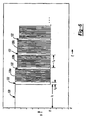
- Power may be supplied to the motor 32 over all or a portion of a cycle using a pulse-width modulation technique, an example of which is illustrated in Figure 6 .
- the cycle which may be initiated by a predetermined event, such as the actuation of the trigger 18, may include an initial power interval 120 and one or more supplemental power intervals (e.g., 126a, 126b, 126c).
- the initial power interval 120 may be an interval over which the full voltage of the battery 26 may be employed to power the motor 32.
- the length or duration (ti) of the initial power interval 120 may be determined through an algorithm or a look-up table in the memory of the controller 54 for example, based on the output of the battery 26 or on an operating characteristic, such as rotational speed, of a component in the motor assembly 14.
- the length or duration (ts) of each supplemental power interval may equal that of the initial power interval 120, or may be a predetermined constant, or may be varied based on the output of the battery 26 or on an operating characteristic of the motor assembly
- a dwell interval 122 may be employed between the initial power interval 120 and a first supplemental power interval 126a and/or between successive supplemental power intervals.
- the dwell intervals 122 may be of a varying length or duration (td), but in the particular example provided, the dwell intervals 122 are of a constant duration (td).
- power to the motor 32 may be interrupted so as to permit the motor 32 to "coast".
- the output of the power source sensor 52 may be employed during this time to evaluate the level of kinetic energy in the motor assembly 14 (e.g., to permit the controller 54 to determine whether the motor assembly 14 has sufficient energy to drive a fastener) and/or to determine one or more parameters by which the motor 32 may be powered or operated in a subsequent power interval.
- the controller 54 evaluates the back emf of the motor 32 to approximate the speed of the flywheel 34.
- the approximate speed of the flywheel 34 (or an equivalent thereof, such as the value of the back emf of the motor 32) may be employed in an algorithm or look-up table to determine the duty cycle (e.g., apparent voltage) of the next supplemental power interval.
- an algorithm or look-up table may be employed to calculate changes to the duration (ti) of the initial power interval 120. In this way, the value (ti) may be constantly updated as the battery 26 is discharged.
- the value (ti) may be reset (e.g., to a value that may be stored in a look-up table) when a battery 26 is initially coupled to the controller 54.
- the controller 54 may set (ti) equal to 180ms if the battery 26 has a nominal voltage of about 18 volts, or to 200ms if the battery 26 has a nominal voltage of about 14.4 volts, or to 240ms if the battery 26 has a nominal voltage of about 12 volts.
- the back-emf of the motor 32 may change with the temperature of the motor as is indicated by the line that is designated by reference numeral 200; the line 200 represents the actual rotational speed as a function of temperature when the back-emf of the motor is held constant.
- the control unit 22 may include a temperature sensor 202 for sensing a temperature of the motor 32 or another portion of the fastening tool, such as the controller 54, to permit the controller 54 to compensate for differences in the back-emf of the motor 32 that occur with changes in temperature.
- the temperature sensor 202 is coupled to the controller 54 and generates a temperature signal in response to a sensed temperature of the controller 54. As the controller 54 is in relatively close proximity to the motor 32, the temperature of the controller 54 approximates the temperature of the motor 32.
- the controller 54 may employ any known technique, such as a look-up table, mathematical relationship or an algorithm, to determine the effect of the sensed temperature on the back-emf of the motor 32.
- the line designated by reference numeral 210 in Figure 8 illustrates the actual speed of the motor 32 as a function of temperature when the approximate rotational speed (S) is held constant.
- ⁇ S BEF can be a term that is employed to modify the base speed of the motor 32 based upon the back-emf produced by the motor 32
- ⁇ S T can be the temperature-based speed differential described above.
- the voltage of the battery can be an actual battery voltage as opposed to a nominal battery voltage and the S BATV term can be derived as a function of the slope of a plot of motor speed versus battery voltage.
- the speed of the motor can be determined in a manner that is highly accurate over a wide temperature range.
- the fastening tool 10 has been described as providing electrical power to the electric motor 32 except for relatively short duration intervals (e.g., between pulses and/or to check the back-emf of the motor 32) throughout an operational cycle
- the controller 54 may control the operation of the motor 32 through feedback control wherein electric power is occasionally interrupted so as to allow the motor 32 and flywheel 34 to "coast".
- the controller 54 can occasionally monitor the kinetic energy of the motor assembly 14 and apply power to the motor if the kinetic energy of the motor assembly 14 falls below a predetermined threshold. Operation of the fastening tool in this manner can improve battery life.
Claims (27)
- Werkzeug (10) zum Eintreiben von Befestigungselementen für ein Anordnen von Befestigungselementen in einem Werkstück, wobei das Werkzeug zum Eintreiben von Befestigungselementen umfasst:einen Kontaktanschlagschalter (50), der in Reaktion auf eine erste Eingabe eines Benutzers betätigt wird,einen Auslöseschalter (18a), der in Reaktion auf eine zweite Eingabe eines Benutzers betätigt wird,ein Eintreibelement (28), das entlang einer Achse beweglich ist, undeine Motoranordnung (14) mit einem Schwungrad (34), das durch einen Motor angetrieben wird, und einem Betätiger (36), das betätigt werden kann, um das Eintreibelement in Eingriff mit dem Schwungrad zu drücken, so dass sich das Eintreibelement entlang der Achse bewegt,gekennzeichnet durch eine Steuerung (54), die aufgebaut ist, um wahlweise die Motoranordnung zu aktivieren, um das Eintreibelement zu veranlassen, sich zumindest teilweise entlang der Achse zu bewegen in Reaktion auf eine Betätigung des Auslöseanschlagschalters und des Betätigungsschalters, wobei die Steuerung einen Betriebsartenwählschalter (60) mit einem ersten Schalterzustand und einem zweiten Schalterzustand umfasst, wobei ein Einstellen des Betriebsartenwählschalters in den ersten Schalterzustand erfordert, dass der Kontaktanschlagschalter vor der Betätigung des Auslöseschalters betätigt wird, bevor die Steuerung den Betätiger betätigt, und wobei ein Einstellen des Betriebsartenwählschalters in den zweiten Schalterzustand der Steuerung erlaubt, den Betätiger zu aktivieren, wenn sowohl der Kontaktanschlagschalter als auch der Auslöseschalter aktiviert worden sind, unabhängig von einer Reihenfolge, in der der Kontaktanschlagschalter und der Auslöseschalter aktiviert worden sind.
- Werkzeug zum Eintreiben von Befestigungselementen nach Anspruch 1, wobei die Steuerung den Motor aktiviert, wenn der Kontaktanschlagschalter oder der Auslöseschalter betätigt worden sind.
- Werkzeug zum Eintreiben von Befestigungselementen nach Anspruch 1 oder 2, ferner mit einer Abdeckung (62), die wahlweise von dem Werkzeugkörper entfernt werden kann, wobei ein Verbinden der Abdeckung mit dem Werkzeugkörper den Betriebsartenwählschalter abdeckt und unsichtbar macht.
- Werkzeug zum Eintreiben von Befestigungselementen nach Anspruch 3, wobei der Betriebsartenwählschalter ein elektrischer Schalter ist, der ein Schaltsignal erzeugt, das abhängig ist von einer Stellung, in die der Betriebsartenwählschalter gesetzt wird.
- Werkzeug zum Eintreiben von Befestigungselementen nach Anspruch 3 oder 4, wobei ein Verbinden der Abdeckung mit dem Werkzeugkörper verhindert, dass ein Zustand des Betriebsartenwählschalters verändert wird.
- Werkzeug zum Eintreiben von Befestigungselementen nach einem der Ansprüche 3 bis 5, wobei die Abdeckung aus einem elastischen Material gebildet ist.
- Werkzeug zum Eintreiben von Befestigungselementen nach einem der vorhergehenden Ansprüche, wobei ein Positionieren des Betriebsartenwählschalters in dem ersten Schalterzustand der Steuerung ein erstes vorbestimmtes Signal zuführt, wobei ein Positionieren des Betriebsartenwählschalters in dem zweiten Schalterzustand der Steuerung ein zweites vorbestimmtes Signal zuführt, wobei das zweite vorbestimmte Signal unterschiedlich zu dem ersten vorbestimmten Signal ist.
- Werkzeug zum Eintreiben von Befestigungselementen nach Anspruch 7, wobei die Steuerung standardmäßig in einen Zustand übergeht, in dem die erste Eingabe eines Benutzers vor der zweiten Eingabe eines Benutzers empfangen werden muss, bevor die Steuerung die Stromquelle aktiviert, wenn das zweite vorbestimmte Signal nicht von dem Betriebsartenwählschalter empfangen wird.
- Werkzeug zum Eintreiben von Befestigungselementen nach Anspruch 7 oder 8, wobei das erste vorbestimmte Signal ein Signal mit einer ersten Spannung ist und das zweite vorbestimmte Signal ein Signal mit einer zweiten Spannung.
- Werkzeug (10) zum Eintreiben von Befestigungselementen für ein Anordnen von Befestigungselementen in einem Werkstück, wobei das Werkzeug zum Eintreiben von Befestigungselementen aufweist:ein Nasenstück (16),einen Kontaktanschlag (20), der mit dem Nasenstück verbunden ist und zwischen einer ersten Kontaktanschlagstellung und einer zweiten Kontaktanschlagstellung beweglich ist, wobei der Kontaktanschlag in die erste Kontaktanschlagstellung vorgespannt ist und sich in die zweite Kontaktanschlagstellung in Reaktion auf eine erste Eingabe eines Benutzers bewegt,einen Werkzeugkörper (12a), der mit dem Nasenstück verbunden ist,ein Eintreibelement (28), das in dem Werkzeugkörper aufgenommen und entlang einer Achse durch wenigstens einen Teil des Nasenstücks bewegbar ist,eine Motoranordnung (14) zum Verlagern des Eintreibelements entlang der Achse undeinen Auslöser (18), der mit dem Werkzeugkörper verbunden ist, wobei der Auslöser zwischen einer ersten Auslöserstellung und einer zweiten Auslöserstellung beweglich ist, wobei der Auslöser in die erste Auslöserstellung vorgespannt ist und sich in die zweite Auslöserstellung in Reaktion auf eine zweite Eingabe eines Benutzers bewegt,gekennzeichnet durch eine Steuerung (54), die aufgebaut ist, um die Motoranordnung wahlweise zu aktivieren, wobei die Steuerung eine Betriebsartenwähleinrichtung (60) mit einem ersten Zustand und einem zweiten Zustand umfasst, wobei ein Einstellen der Betriebsartenwähleinrichtung in dem ersten Zustand erfordert, dass der Kontaktanschlag vor einer Bewegung des Auslösers in die zweite Auslöserstellung in die zweite Kontaktanschlagstellung bewegt wird, um die Motoranordnung zu betätigen und das Eintreibelement zu veranlassen, sich entlang der Achse zu verlagern, und wobei ein Einstellen der Betriebsartenwähleinrichtung in dem zweiten Zustand der Steuerung erlaubt, die Motoranordnung zu aktivieren und das Eintreibelement zu veranlassen, sich entlang der Achse zu verlagern, unabhängig von einer Reihenfolge, in der der Kontaktanschlag in die zweite Kontaktanschlagstellung bewegt wird und der Auslöser in die zweite Auslöserstellung.
- Werkzeug zum Eintreiben von Befestigungselementen nach Anspruch 10, ferner mit einer Abdeckung (62), die wahlweise von dem Werkzeugkörper entfernt werden kann, wobei ein Verbinden der Abdeckung mit dem Werkzeugkörper die Betriebsartenwähleinrichtung abdeckt und unsichtbar macht.
- Werkzeug zum Eintreiben von Befestigungselementen nach Anspruch 11, wobei die Betriebsartenwähleinrichtung ein elektrischer Schalter ist, der ein Schaltsignal erzeugt, das abhängig ist von einer Stellung, in die die Betriebsartenwähleinrichtung gesetzt wird.
- Werkzeug zum Eintreiben von Befestigungselementen nach Anspruch 11 oder 12, wobei ein Verbinden der Abdeckung mit dem Werkzeugkörper verhindert, dass ein Zustand der Betriebsartenwähleinrichtung verändert wird.
- Werkzeug zum Eintreiben von Befestigungselementen nach einem der Ansprüche 11 bis 13, wobei die Abdeckung aus einem elastischen Material gebildet ist.
- Werkzeug zum Eintreiben von Befestigungselementen nach einem der Ansprüche 10 bis 14, wobei ein Positionieren der Betriebsartenwähleinrichtung in dem ersten Zustand der Steuerung ein erstes vorbestimmtes Signal zuführt, wobei ein Positionieren der Betriebsartenwähleinrichtung in dem zweiten Zustand der Steuerung ein zweites vorbestimmtes Signal zuführt, wobei sich das zweite vorbestimmte Signal von dem ersten vorbestimmten Signal unterscheidet.
- Werkzeug zum Eintreiben von Befestigungselementen nach Anspruch 15, wobei die Steuerung standardmäßig in einen Zustand übergeht, in dem der Kontaktanschlag vor einer Bewegung des Auslösers in die zweite Auslöserstellung in die zweite Kontaktanschlagstellung bewegt werden muss, um die Motoranordnung zu betätigen und das Eintreibelement zu veranlassen, sich entlang der Achse zu verlagern, wenn die Steuerung nicht das zweite vorbestimmte Signal empfängt.
- Werkzeug zum Eintreiben von Befestigungselementen nach Anspruch 15 oder 16, wobei das erste vorbestimmte Signal ein Signal mit einer ersten Spannung ist und wobei das zweite vorbestimmte Signal ein Signal mit einer zweiten Spannung ist.
- Werkzeug (10) zum Eintreiben von Befestigungselementen für ein Anordnen von Befestigungselementen in einem Werkstück, wobei das Werkzeug zum Eintreiben von Befestigungselementen aufweist:einen Werkzeugkörper (12a),einen Kontaktanschlag (20), der mit dem Werkzeugkörper verbunden ist und zwischen einer ersten Kontaktanschlagstellung und einer zweiten Kontaktanschlagstellung beweglich ist, wobei der Kontaktanschlag in die erste Kontaktanschlagstellung vorgespannt ist und sich in die zweite Kontaktanschlagstellung in Reaktion auf eine erste Eingabe eines Benutzers bewegt,ein Eintreibelement (28), das in dem Werkzeugkörper aufgenommen und entlang einer Achse beweglich ist,eine Motoranordnung (14) zum Verlagern des Eintreibelements entlang der Achse, wobei die Motoranordnung ein Schwungrad (34) und einen Betätiger (36) umfasst, wobei das Eintreibelement zwischen dem Schwungrad und dem Betätiger angeordnet ist, undeinen Auslöser (18), der mit dem Werkzeugkörper verbunden ist, wobei der Auslöser zwischen einer ersten Auslöserstellung und einer zweiten Auslöserstellung beweglich ist, wobei der Auslöser in die erste Auslöserstellung vorgespannt ist und sich in die zweite Auslöserstellung in Reaktion auf eine zweite Eingabe eines Benutzers bewegt,gekennzeichnet durch eine Steuerung (54), die aufgebaut ist, um den Betätiger wahlweise zu bewegen, um das Eintreibelement zwischen ein Betätiger und das Schwungrad zu drücken, wobei die Steuerung eine Betriebsartenwähleinrichtung (60) mit einem ersten Zustand und einem zweiten Zustand umfasst, wobei ein Einstellen der Betriebsartenwähleinrichtung in den ersten Zustand eine sequenzielle Betriebsweise des Werkzeugs zum Eintreiben von Befestigungselementen erfordert und wobei ein Einstellen der Betriebsartenwähleinrichtung in den zweiten Zustand erlaubt, das Werkzeug zum Eintreiben von Befestigungselementen in einer unterschiedlichen Betriebsweise zu betreiben.
- Werkzeug zum Eintreiben von Befestigungselementen nach Anspruch 18, wobei die unterschiedliche Betriebsweise eine Stoß-Zuführ-Betriebsweise ist.
- Werkzeug zum Eintreiben von Befestigungselementen nach Anspruch 18 oder 19, wobei ein Positionieren der Betriebsartenwähleinrichtung in dem ersten Zustand der Steuerung ein erstes vorbestimmtes Signal zuführt, und wobei ein Positionieren der Betriebsartenwähleinrichtung in dem zweiten Zustand der Steuerung ein zweites vorbestimmtes Signal zuführt, wobei sich das zweite vorbestimmte Signal von dem ersten vorbestimmten Signal unterscheidet.
- Werkzeug zum Eintreiben von Befestigungselementen nach Anspruch 20, wobei die Steuerung standarmäßig in einen Zustand übergeht, der nur die sequenzielle Zuführ-Betriebsart erlaubt, wenn die Steuerung nicht das zweite vorbestimmte Signal empfängt.
- Werkzeug zum Eintreiben von Befestigungselementen nach Anspruch 20 oder 21, wobei das erste und zweite vorbestimmte Signal elektrische Signale sind.
- Werkzeug (10) zum Eintreiben von Befestigungselementen mit:einem Werkzeugkörper (12a),einem Eintreibelement (28), das an dem Werkzeugkörper angebracht und entlang einer Achse beweglich ist,einer Motoranordnung (14), die aufgebaut ist, das Antriebselement entlang der Achse anzutreiben,einem Kontaktanschlag (20), der mit dem Werkzeugkörper verbunden und zwischen einem ersten Kontaktanschlagzustand und einem zweiten Kontaktanschlagzustand beweglich ist, wobei der Kontaktanschlag in den ersten Kontaktanschlagzustand vorgespannt und in den zweiten Kontaktanschlagzustand in Reaktion auf eine erste Eingabe eines Benutzers beweglich ist, undeinen Auslöser (18), der mit dem Werkzeugkörper verbunden und zwischen einem ersten Auslöserzustand und einem zweiten Auslöserzustand beweglich ist, wobei der Auslöser in den ersten Auslöserzustand vorgespannt und in den zweiten Auslöserzustand in Reaktion auf eine zweite Eingabe eines Benutzers beweglich ist,gekennzeichnet durch eine elektronische Steuerung (54), die mit der Motoranordnung verbunden und betätigbar ist, um die Motoranordnung zu betätigen, um das Eintreibelement entlang der Achse zu bewegen, wobei die elektronische Steuerung in einer ersten Betriebsweise betreibbar ist, in der die Motoranordnung nur betätigt wird, wenn der Kontaktanschlag vor einer Bewegung des Auslösers in den zweiten Auslöserzustand in den zweiten Kontaktanschlagzustand bewegt wird, und einer zweiten Betriebsweise, die der Motoranordnung erlaubt, betätigt zu werden, wenn der Auslöser vor einer Bewegung des Kontaktanschlags in den zweiten Kontaktanschlagzustand in den zweiten Auslöserzustand bewegr wird.
- Werkzeug zum Eintreiben von Befestigungselementen nach Anspruch 23, wobei die Motoranordnung einen Elektromotor (32) umfasst.
- Werkzeug zum Eintreiben von Befestigungselementen nach Anspruch 24, wobei der Elektromotor ein Schwungrad (34) antreibt.
- Werkzeug zum Eintreiben von Befestigungselementen nach Anspruch 25, wobei die Motoranordnung ferner einen Betätiger (36) mit einem Druckelement (46) umfasst und wobei ein Betätigen der Motoranordnung ein Bewegen des Druckelements umfasst, um das Eintreibelement in Kontakt mit dem Schwungrad zu treiben.
- Verfahren umfassend:Bereitstellen eines elektrischen Werkzeugs (10) zum Eintreiben von Befestigungselementen mit einem Kontaktanschlag (20), einem Auslöser (18), einem Eintreibelement (28), das entlang einer Achse beweglich ist, und einem Betriebsartenwählschalter (60), wobei der Betriebsartenwählschalter eine sequenzielle Einstellung und eine Stoß-Zuführ-Einstellung hat,gekennzeichnet durch ein Anordnen des Betriebsartenwählschalters in der Stoß-Zuführ-Einstellung, undBetreiben des Werkzeugs, so dassa) der Auslöser in einen betätigten Zustand bewegt wird,b) der Kontaktanschlag in einen betätigten Zustand bewegt wird, nachdem der Auslöser in den betätigten Zustand bewegt worden ist, undc) das Eintreibelement entlang der Achse verlagert wird, ohne zuvor den Auslöser in einen nicht betätigten Zustand zu verändern.
Applications Claiming Priority (2)
| Application Number | Priority Date | Filing Date | Title |
|---|---|---|---|
| US55934904P | 2004-04-02 | 2004-04-02 | |
| US559349P | 2004-04-02 |
Publications (2)
| Publication Number | Publication Date |
|---|---|
| EP1584418A1 EP1584418A1 (de) | 2005-10-12 |
| EP1584418B1 true EP1584418B1 (de) | 2008-05-07 |
Family
ID=34886352
Family Applications (4)
| Application Number | Title | Priority Date | Filing Date |
|---|---|---|---|
| EP05006843A Not-in-force EP1584418B1 (de) | 2004-04-02 | 2005-03-30 | Befestigungswerkzeug mit Moduswahlschalter |
| EP20050006836 Ceased EP1591208A1 (de) | 2004-04-02 | 2005-03-30 | Elektronisches Befestigungsgerät |
| EP05006981A Not-in-force EP1584419B1 (de) | 2004-04-02 | 2005-03-31 | Verfahren zum Benutzen eines Leistungstreibers |
| EP05006982A Not-in-force EP1582299B1 (de) | 2004-04-02 | 2005-03-31 | Verfahren zum Kontrollieren eines Leistungstreibers |
Family Applications After (3)
| Application Number | Title | Priority Date | Filing Date |
|---|---|---|---|
| EP20050006836 Ceased EP1591208A1 (de) | 2004-04-02 | 2005-03-30 | Elektronisches Befestigungsgerät |
| EP05006981A Not-in-force EP1584419B1 (de) | 2004-04-02 | 2005-03-31 | Verfahren zum Benutzen eines Leistungstreibers |
| EP05006982A Not-in-force EP1582299B1 (de) | 2004-04-02 | 2005-03-31 | Verfahren zum Kontrollieren eines Leistungstreibers |
Country Status (6)
| Country | Link |
|---|---|
| US (1) | US8347978B2 (de) |
| EP (4) | EP1584418B1 (de) |
| CN (9) | CN201054324Y (de) |
| AT (3) | ATE394200T1 (de) |
| DE (3) | DE602005006462D1 (de) |
| TW (4) | TW200607621A (de) |
Families Citing this family (464)
| Publication number | Priority date | Publication date | Assignee | Title |
|---|---|---|---|---|
| US9060770B2 (en) | 2003-05-20 | 2015-06-23 | Ethicon Endo-Surgery, Inc. | Robotically-driven surgical instrument with E-beam driver |
| US20070084897A1 (en) | 2003-05-20 | 2007-04-19 | Shelton Frederick E Iv | Articulating surgical stapling instrument incorporating a two-piece e-beam firing mechanism |
| US7322506B2 (en) * | 2004-04-02 | 2008-01-29 | Black & Decker Inc. | Electric driving tool with driver propelled by flywheel inertia |
| US11896225B2 (en) | 2004-07-28 | 2024-02-13 | Cilag Gmbh International | Staple cartridge comprising a pan |
| US8215531B2 (en) | 2004-07-28 | 2012-07-10 | Ethicon Endo-Surgery, Inc. | Surgical stapling instrument having a medical substance dispenser |
| US7669746B2 (en) | 2005-08-31 | 2010-03-02 | Ethicon Endo-Surgery, Inc. | Staple cartridges for forming staples having differing formed staple heights |
| US9237891B2 (en) | 2005-08-31 | 2016-01-19 | Ethicon Endo-Surgery, Inc. | Robotically-controlled surgical stapling devices that produce formed staples having different lengths |
| US11246590B2 (en) | 2005-08-31 | 2022-02-15 | Cilag Gmbh International | Staple cartridge including staple drivers having different unfired heights |
| US11484312B2 (en) | 2005-08-31 | 2022-11-01 | Cilag Gmbh International | Staple cartridge comprising a staple driver arrangement |
| US10159482B2 (en) | 2005-08-31 | 2018-12-25 | Ethicon Llc | Fastener cartridge assembly comprising a fixed anvil and different staple heights |
| US7934630B2 (en) | 2005-08-31 | 2011-05-03 | Ethicon Endo-Surgery, Inc. | Staple cartridges for forming staples having differing formed staple heights |
| US20070106317A1 (en) | 2005-11-09 | 2007-05-10 | Shelton Frederick E Iv | Hydraulically and electrically actuated articulation joints for surgical instruments |
| DE102005000157B3 (de) * | 2005-11-16 | 2007-04-05 | Hilti Ag | Befestigungsmittel-Zuführeinrichtung für ein handgeführtes kraftbetriebenes Eintreibgerät |
| US11278279B2 (en) | 2006-01-31 | 2022-03-22 | Cilag Gmbh International | Surgical instrument assembly |
| US11224427B2 (en) | 2006-01-31 | 2022-01-18 | Cilag Gmbh International | Surgical stapling system including a console and retraction assembly |
| US11793518B2 (en) | 2006-01-31 | 2023-10-24 | Cilag Gmbh International | Powered surgical instruments with firing system lockout arrangements |
| US8186555B2 (en) | 2006-01-31 | 2012-05-29 | Ethicon Endo-Surgery, Inc. | Motor-driven surgical cutting and fastening instrument with mechanical closure system |
| US20110024477A1 (en) | 2009-02-06 | 2011-02-03 | Hall Steven G | Driven Surgical Stapler Improvements |
| US20120292367A1 (en) | 2006-01-31 | 2012-11-22 | Ethicon Endo-Surgery, Inc. | Robotically-controlled end effector |
| US20110290856A1 (en) | 2006-01-31 | 2011-12-01 | Ethicon Endo-Surgery, Inc. | Robotically-controlled surgical instrument with force-feedback capabilities |
| US8708213B2 (en) | 2006-01-31 | 2014-04-29 | Ethicon Endo-Surgery, Inc. | Surgical instrument having a feedback system |
| US7845537B2 (en) | 2006-01-31 | 2010-12-07 | Ethicon Endo-Surgery, Inc. | Surgical instrument having recording capabilities |
| US8820603B2 (en) | 2006-01-31 | 2014-09-02 | Ethicon Endo-Surgery, Inc. | Accessing data stored in a memory of a surgical instrument |
| US7753904B2 (en) | 2006-01-31 | 2010-07-13 | Ethicon Endo-Surgery, Inc. | Endoscopic surgical instrument with a handle that can articulate with respect to the shaft |
| US8992422B2 (en) | 2006-03-23 | 2015-03-31 | Ethicon Endo-Surgery, Inc. | Robotically-controlled endoscopic accessory channel |
| US8322455B2 (en) | 2006-06-27 | 2012-12-04 | Ethicon Endo-Surgery, Inc. | Manually driven surgical cutting and fastening instrument |
| JP2008068355A (ja) * | 2006-09-14 | 2008-03-27 | Hitachi Koki Co Ltd | 電動式打込機 |
| JP4692932B2 (ja) * | 2006-09-14 | 2011-06-01 | 日立工機株式会社 | 電動式打込機 |
| US10568652B2 (en) | 2006-09-29 | 2020-02-25 | Ethicon Llc | Surgical staples having attached drivers of different heights and stapling instruments for deploying the same |
| US8348131B2 (en) | 2006-09-29 | 2013-01-08 | Ethicon Endo-Surgery, Inc. | Surgical stapling instrument with mechanical indicator to show levels of tissue compression |
| US7427008B2 (en) | 2006-10-25 | 2008-09-23 | Black & Decker Inc. | Depth adjusting device for a power tool |
| US20080110652A1 (en) * | 2006-11-14 | 2008-05-15 | Wan-Fu Wen | Method of Detecting Nail Storage State |
| US8684253B2 (en) | 2007-01-10 | 2014-04-01 | Ethicon Endo-Surgery, Inc. | Surgical instrument with wireless communication between a control unit of a robotic system and remote sensor |
| US8652120B2 (en) | 2007-01-10 | 2014-02-18 | Ethicon Endo-Surgery, Inc. | Surgical instrument with wireless communication between control unit and sensor transponders |
| US11291441B2 (en) | 2007-01-10 | 2022-04-05 | Cilag Gmbh International | Surgical instrument with wireless communication between control unit and remote sensor |
| US8540128B2 (en) | 2007-01-11 | 2013-09-24 | Ethicon Endo-Surgery, Inc. | Surgical stapling device with a curved end effector |
| US11039836B2 (en) | 2007-01-11 | 2021-06-22 | Cilag Gmbh International | Staple cartridge for use with a surgical stapling instrument |
| US7438209B1 (en) | 2007-03-15 | 2008-10-21 | Ethicon Endo-Surgery, Inc. | Surgical stapling instruments having a releasable staple-forming pocket |
| US7646157B2 (en) | 2007-03-16 | 2010-01-12 | Black & Decker Inc. | Driving tool and method for controlling same |
| US8893946B2 (en) | 2007-03-28 | 2014-11-25 | Ethicon Endo-Surgery, Inc. | Laparoscopic tissue thickness and clamp load measuring devices |
| US11857181B2 (en) | 2007-06-04 | 2024-01-02 | Cilag Gmbh International | Robotically-controlled shaft based rotary drive systems for surgical instruments |
| US8931682B2 (en) | 2007-06-04 | 2015-01-13 | Ethicon Endo-Surgery, Inc. | Robotically-controlled shaft based rotary drive systems for surgical instruments |
| US7556184B2 (en) * | 2007-06-11 | 2009-07-07 | Black & Decker Inc. | Profile lifter for a nailer |
| US7753245B2 (en) | 2007-06-22 | 2010-07-13 | Ethicon Endo-Surgery, Inc. | Surgical stapling instruments |
| JP5133000B2 (ja) * | 2007-06-28 | 2013-01-30 | 株式会社マキタ | 電動打ち込み工具 |
| JP5073380B2 (ja) * | 2007-06-28 | 2012-11-14 | 株式会社マキタ | 電動打ち込み工具 |
| US11849941B2 (en) | 2007-06-29 | 2023-12-26 | Cilag Gmbh International | Staple cartridge having staple cavities extending at a transverse angle relative to a longitudinal cartridge axis |
| EP2243600B1 (de) | 2007-10-05 | 2015-11-25 | Senco Brands, Inc | Eintreibwerkzeug mit Gasfeder für Befestigungsmittel und Verfahren für die Werkzeugkontrolle |
| US9179912B2 (en) | 2008-02-14 | 2015-11-10 | Ethicon Endo-Surgery, Inc. | Robotically-controlled motorized surgical cutting and fastening instrument |
| US7866527B2 (en) | 2008-02-14 | 2011-01-11 | Ethicon Endo-Surgery, Inc. | Surgical stapling apparatus with interlockable firing system |
| RU2493788C2 (ru) | 2008-02-14 | 2013-09-27 | Этикон Эндо-Серджери, Инк. | Хирургический режущий и крепежный инструмент, имеющий радиочастотные электроды |
| US8636736B2 (en) | 2008-02-14 | 2014-01-28 | Ethicon Endo-Surgery, Inc. | Motorized surgical cutting and fastening instrument |
| US8573465B2 (en) | 2008-02-14 | 2013-11-05 | Ethicon Endo-Surgery, Inc. | Robotically-controlled surgical end effector system with rotary actuated closure systems |
| US7819298B2 (en) | 2008-02-14 | 2010-10-26 | Ethicon Endo-Surgery, Inc. | Surgical stapling apparatus with control features operable with one hand |
| US8758391B2 (en) | 2008-02-14 | 2014-06-24 | Ethicon Endo-Surgery, Inc. | Interchangeable tools for surgical instruments |
| US10390823B2 (en) | 2008-02-15 | 2019-08-27 | Ethicon Llc | End effector comprising an adjunct |
| US8608044B2 (en) * | 2008-02-15 | 2013-12-17 | Ethicon Endo-Surgery, Inc. | Feedback and lockout mechanism for surgical instrument |
| US11272927B2 (en) | 2008-02-15 | 2022-03-15 | Cilag Gmbh International | Layer arrangements for surgical staple cartridges |
| CN100553889C (zh) * | 2008-06-20 | 2009-10-28 | 北京大风时代科技有限责任公司 | 一种具有杠杆的高速电磁钉枪 |
| US7934565B2 (en) * | 2008-08-14 | 2011-05-03 | Robert Bosch Gmbh | Cordless nailer with safety sensor |
| US9386983B2 (en) | 2008-09-23 | 2016-07-12 | Ethicon Endo-Surgery, Llc | Robotically-controlled motorized surgical instrument |
| US8210411B2 (en) | 2008-09-23 | 2012-07-03 | Ethicon Endo-Surgery, Inc. | Motor-driven surgical cutting instrument |
| US9005230B2 (en) | 2008-09-23 | 2015-04-14 | Ethicon Endo-Surgery, Inc. | Motorized surgical instrument |
| US11648005B2 (en) | 2008-09-23 | 2023-05-16 | Cilag Gmbh International | Robotically-controlled motorized surgical instrument with an end effector |
| US8608045B2 (en) | 2008-10-10 | 2013-12-17 | Ethicon Endo-Sugery, Inc. | Powered surgical cutting and stapling apparatus with manually retractable firing system |
| US8517239B2 (en) | 2009-02-05 | 2013-08-27 | Ethicon Endo-Surgery, Inc. | Surgical stapling instrument comprising a magnetic element driver |
| US8444036B2 (en) | 2009-02-06 | 2013-05-21 | Ethicon Endo-Surgery, Inc. | Motor driven surgical fastener device with mechanisms for adjusting a tissue gap within the end effector |
| BRPI1008667A2 (pt) | 2009-02-06 | 2016-03-08 | Ethicom Endo Surgery Inc | aperfeiçoamento do grampeador cirúrgico acionado |
| US8631986B2 (en) * | 2009-12-04 | 2014-01-21 | Robert Bosch Gmbh | Fastener driver with an operating switch |
| US8851354B2 (en) | 2009-12-24 | 2014-10-07 | Ethicon Endo-Surgery, Inc. | Surgical cutting instrument that analyzes tissue thickness |
| US8220688B2 (en) | 2009-12-24 | 2012-07-17 | Ethicon Endo-Surgery, Inc. | Motor-driven surgical cutting instrument with electric actuator directional control assembly |
| US8875804B2 (en) * | 2010-01-07 | 2014-11-04 | Black & Decker Inc. | Screwdriving tool having a driving tool with a removable contact trip assembly |
| ES2534354T3 (es) * | 2010-03-31 | 2015-04-21 | Alfing Montagetechnik Gmbh | Dispositivo de montaje y procedimiento de montaje |
| TWI385058B (zh) * | 2010-04-26 | 2013-02-11 | Basso Ind Corp | Electric nail gun drive device |
| DE102010030055A1 (de) * | 2010-06-15 | 2011-12-15 | Hilti Aktiengesellschaft | Elektrisch betreibbares Bolzensetzgerät und Verfahren zum Betreiben des Bolzensetzgerätes |
| US8783543B2 (en) | 2010-07-30 | 2014-07-22 | Ethicon Endo-Surgery, Inc. | Tissue acquisition arrangements and methods for surgical stapling devices |
| TWI381915B (zh) * | 2010-09-16 | 2013-01-11 | Basso Ind Corp | An electric nail gun with an error prevention function |
| US9566061B2 (en) | 2010-09-30 | 2017-02-14 | Ethicon Endo-Surgery, Llc | Fastener cartridge comprising a releasably attached tissue thickness compensator |
| US11812965B2 (en) | 2010-09-30 | 2023-11-14 | Cilag Gmbh International | Layer of material for a surgical end effector |
| US9364233B2 (en) | 2010-09-30 | 2016-06-14 | Ethicon Endo-Surgery, Llc | Tissue thickness compensators for circular surgical staplers |
| US9241714B2 (en) | 2011-04-29 | 2016-01-26 | Ethicon Endo-Surgery, Inc. | Tissue thickness compensator and method for making the same |
| US11298125B2 (en) | 2010-09-30 | 2022-04-12 | Cilag Gmbh International | Tissue stapler having a thickness compensator |
| US10945731B2 (en) | 2010-09-30 | 2021-03-16 | Ethicon Llc | Tissue thickness compensator comprising controlled release and expansion |
| US9386988B2 (en) | 2010-09-30 | 2016-07-12 | Ethicon End-Surgery, LLC | Retainer assembly including a tissue thickness compensator |
| US8740038B2 (en) | 2010-09-30 | 2014-06-03 | Ethicon Endo-Surgery, Inc. | Staple cartridge comprising a releasable portion |
| US11925354B2 (en) | 2010-09-30 | 2024-03-12 | Cilag Gmbh International | Staple cartridge comprising staples positioned within a compressible portion thereof |
| US9629814B2 (en) | 2010-09-30 | 2017-04-25 | Ethicon Endo-Surgery, Llc | Tissue thickness compensator configured to redistribute compressive forces |
| US9517063B2 (en) | 2012-03-28 | 2016-12-13 | Ethicon Endo-Surgery, Llc | Movable member for use with a tissue thickness compensator |
| US8695866B2 (en) | 2010-10-01 | 2014-04-15 | Ethicon Endo-Surgery, Inc. | Surgical instrument having a power control circuit |
| TWM403405U (en) * | 2010-11-03 | 2011-05-11 | Basso Ind Corp | Control structure of electrical nailing gun |
| TWI401143B (zh) * | 2010-11-03 | 2013-07-11 | Basso Ind Corp | Electric nail gun double switch device |
| AU2012250197B2 (en) | 2011-04-29 | 2017-08-10 | Ethicon Endo-Surgery, Inc. | Staple cartridge comprising staples positioned within a compressible portion thereof |
| US11207064B2 (en) | 2011-05-27 | 2021-12-28 | Cilag Gmbh International | Automated end effector component reloading system for use with a robotic system |
| US9072535B2 (en) | 2011-05-27 | 2015-07-07 | Ethicon Endo-Surgery, Inc. | Surgical stapling instruments with rotatable staple deployment arrangements |
| WO2012167241A1 (en) | 2011-06-02 | 2012-12-06 | Black & Decker Inc. | Control system for a fastening power tool |
| US8991675B2 (en) | 2011-12-19 | 2015-03-31 | De Poan Pneumatic Corp. | Dynamic clutch apparatus for electrical nail gun |
| US9044230B2 (en) | 2012-02-13 | 2015-06-02 | Ethicon Endo-Surgery, Inc. | Surgical cutting and fastening instrument with apparatus for determining cartridge and firing motion status |
| CN103286727B (zh) * | 2012-03-02 | 2015-06-10 | 南京德朔实业有限公司 | 可调节扭力的冲击扳手 |
| MX353040B (es) | 2012-03-28 | 2017-12-18 | Ethicon Endo Surgery Inc | Unidad retenedora que incluye un compensador de grosor de tejido. |
| BR112014024102B1 (pt) | 2012-03-28 | 2022-03-03 | Ethicon Endo-Surgery, Inc | Conjunto de cartucho de prendedores para um instrumento cirúrgico, e conjunto de atuador de extremidade para um instrumento cirúrgico |
| JP6105041B2 (ja) | 2012-03-28 | 2017-03-29 | エシコン・エンド−サージェリィ・インコーポレイテッドEthicon Endo−Surgery,Inc. | 低圧環境を画定するカプセルを含む組織厚コンペンセーター |
| JP5938652B2 (ja) | 2012-05-10 | 2016-06-22 | パナソニックIpマネジメント株式会社 | 電動工具 |
| DE102012208913A1 (de) * | 2012-05-25 | 2013-11-28 | Robert Bosch Gmbh | Schlagwerkeinheit |
| US11229995B2 (en) | 2012-05-31 | 2022-01-25 | Black Decker Inc. | Fastening tool nail stop |
| US9827658B2 (en) | 2012-05-31 | 2017-11-28 | Black & Decker Inc. | Power tool having latched pusher assembly |
| US9101358B2 (en) | 2012-06-15 | 2015-08-11 | Ethicon Endo-Surgery, Inc. | Articulatable surgical instrument comprising a firing drive |
| US9289256B2 (en) | 2012-06-28 | 2016-03-22 | Ethicon Endo-Surgery, Llc | Surgical end effectors having angled tissue-contacting surfaces |
| US20140001231A1 (en) | 2012-06-28 | 2014-01-02 | Ethicon Endo-Surgery, Inc. | Firing system lockout arrangements for surgical instruments |
| US11202631B2 (en) | 2012-06-28 | 2021-12-21 | Cilag Gmbh International | Stapling assembly comprising a firing lockout |
| BR112014032776B1 (pt) | 2012-06-28 | 2021-09-08 | Ethicon Endo-Surgery, Inc | Sistema de instrumento cirúrgico e kit cirúrgico para uso com um sistema de instrumento cirúrgico |
| US9204879B2 (en) | 2012-06-28 | 2015-12-08 | Ethicon Endo-Surgery, Inc. | Flexible drive member |
| US9649111B2 (en) | 2012-06-28 | 2017-05-16 | Ethicon Endo-Surgery, Llc | Replaceable clip cartridge for a clip applier |
| EP2866686A1 (de) | 2012-06-28 | 2015-05-06 | Ethicon Endo-Surgery, Inc. | Sperrvorrichtung für leeres klammermagazin |
| US20140001234A1 (en) | 2012-06-28 | 2014-01-02 | Ethicon Endo-Surgery, Inc. | Coupling arrangements for attaching surgical end effectors to drive systems therefor |
| US20140001224A1 (en) * | 2012-06-28 | 2014-01-02 | Black & Decker Inc. | Cordless fastening tool control system |
| US10414033B2 (en) | 2012-10-04 | 2019-09-17 | Black & Decker Inc. | Power tool hall effect mode selector switch |
| DE102012223011A1 (de) * | 2012-12-13 | 2014-06-18 | Hilti Aktiengesellschaft | Verfahren zum Betreiben eines handgeführten Arbeitsgeräts |
| MX364729B (es) | 2013-03-01 | 2019-05-06 | Ethicon Endo Surgery Inc | Instrumento quirúrgico con una parada suave. |
| BR112015021098B1 (pt) | 2013-03-01 | 2022-02-15 | Ethicon Endo-Surgery, Inc | Cobertura para uma junta de articulação e instrumento cirúrgico |
| US20140263535A1 (en) * | 2013-03-12 | 2014-09-18 | Techtronic Power Tools Technology Limited | Direct current fastening device and related control methods |
| US9888919B2 (en) | 2013-03-14 | 2018-02-13 | Ethicon Llc | Method and system for operating a surgical instrument |
| US9629629B2 (en) | 2013-03-14 | 2017-04-25 | Ethicon Endo-Surgey, LLC | Control systems for surgical instruments |
| US9867612B2 (en) | 2013-04-16 | 2018-01-16 | Ethicon Llc | Powered surgical stapler |
| BR112015026109B1 (pt) | 2013-04-16 | 2022-02-22 | Ethicon Endo-Surgery, Inc | Instrumento cirúrgico |
| DE102013106658A1 (de) | 2013-06-25 | 2015-01-08 | Illinois Tool Works Inc. | Eintreibwerkzeug zum Eintreiben von Befestigungsmitteln in ein Werkstück |
| DE102013106657A1 (de) * | 2013-06-25 | 2015-01-08 | Illinois Tool Works Inc. | Eintreibwerkzeug zum Eintreiben von Befestigungsmitteln in ein Werkstück |
| EP2826600A1 (de) * | 2013-07-16 | 2015-01-21 | HILTI Aktiengesellschaft | Steuerungsverfahren und Handwerkzeugmaschine |
| TWI458603B (zh) * | 2013-08-01 | 2014-11-01 | Basso Ind Corp | Power tools for heat dissipation devices |
| US9775609B2 (en) | 2013-08-23 | 2017-10-03 | Ethicon Llc | Tamper proof circuit for surgical instrument battery pack |
| MX369362B (es) | 2013-08-23 | 2019-11-06 | Ethicon Endo Surgery Llc | Dispositivos de retraccion de miembros de disparo para instrumentos quirurgicos electricos. |
| JP6297940B2 (ja) * | 2014-01-16 | 2018-03-20 | 株式会社マキタ | 電動機械器具 |
| US9962161B2 (en) | 2014-02-12 | 2018-05-08 | Ethicon Llc | Deliverable surgical instrument |
| BR112016019387B1 (pt) | 2014-02-24 | 2022-11-29 | Ethicon Endo-Surgery, Llc | Sistema de instrumento cirúrgico e cartucho de prendedores para uso com um instrumento cirúrgico de fixação |
| BR112016021943B1 (pt) | 2014-03-26 | 2022-06-14 | Ethicon Endo-Surgery, Llc | Instrumento cirúrgico para uso por um operador em um procedimento cirúrgico |
| US10028761B2 (en) | 2014-03-26 | 2018-07-24 | Ethicon Llc | Feedback algorithms for manual bailout systems for surgical instruments |
| US9826977B2 (en) | 2014-03-26 | 2017-11-28 | Ethicon Llc | Sterilization verification circuit |
| US9820738B2 (en) | 2014-03-26 | 2017-11-21 | Ethicon Llc | Surgical instrument comprising interactive systems |
| JP6636452B2 (ja) | 2014-04-16 | 2020-01-29 | エシコン エルエルシーEthicon LLC | 異なる構成を有する延在部を含む締結具カートリッジ |
| JP6532889B2 (ja) | 2014-04-16 | 2019-06-19 | エシコン エルエルシーEthicon LLC | 締結具カートリッジ組立体及びステープル保持具カバー配置構成 |
| US20150297225A1 (en) | 2014-04-16 | 2015-10-22 | Ethicon Endo-Surgery, Inc. | Fastener cartridges including extensions having different configurations |
| JP6612256B2 (ja) | 2014-04-16 | 2019-11-27 | エシコン エルエルシー | 不均一な締結具を備える締結具カートリッジ |
| US11517315B2 (en) | 2014-04-16 | 2022-12-06 | Cilag Gmbh International | Fastener cartridges including extensions having different configurations |
| US9801628B2 (en) | 2014-09-26 | 2017-10-31 | Ethicon Llc | Surgical staple and driver arrangements for staple cartridges |
| US20160066913A1 (en) | 2014-09-05 | 2016-03-10 | Ethicon Endo-Surgery, Inc. | Local display of tissue parameter stabilization |
| US11311294B2 (en) | 2014-09-05 | 2022-04-26 | Cilag Gmbh International | Powered medical device including measurement of closure state of jaws |
| BR112017004361B1 (pt) | 2014-09-05 | 2023-04-11 | Ethicon Llc | Sistema eletrônico para um instrumento cirúrgico |
| US10105142B2 (en) | 2014-09-18 | 2018-10-23 | Ethicon Llc | Surgical stapler with plurality of cutting elements |
| CN107427300B (zh) | 2014-09-26 | 2020-12-04 | 伊西康有限责任公司 | 外科缝合支撑物和辅助材料 |
| US11523821B2 (en) | 2014-09-26 | 2022-12-13 | Cilag Gmbh International | Method for creating a flexible staple line |
| US10076325B2 (en) | 2014-10-13 | 2018-09-18 | Ethicon Llc | Surgical stapling apparatus comprising a tissue stop |
| US9924944B2 (en) | 2014-10-16 | 2018-03-27 | Ethicon Llc | Staple cartridge comprising an adjunct material |
| US11141153B2 (en) | 2014-10-29 | 2021-10-12 | Cilag Gmbh International | Staple cartridges comprising driver arrangements |
| US10517594B2 (en) | 2014-10-29 | 2019-12-31 | Ethicon Llc | Cartridge assemblies for surgical staplers |
| US9844376B2 (en) | 2014-11-06 | 2017-12-19 | Ethicon Llc | Staple cartridge comprising a releasable adjunct material |
| US10736636B2 (en) | 2014-12-10 | 2020-08-11 | Ethicon Llc | Articulatable surgical instrument system |
| DE102014226162A1 (de) * | 2014-12-17 | 2016-06-23 | Robert Bosch Gmbh | Werkzeug und verfahren zur behandlung eines werkstücks mit einemwerkzeugelement eines werkzeugs |
| US10245027B2 (en) | 2014-12-18 | 2019-04-02 | Ethicon Llc | Surgical instrument with an anvil that is selectively movable about a discrete non-movable axis relative to a staple cartridge |
| US9844375B2 (en) | 2014-12-18 | 2017-12-19 | Ethicon Llc | Drive arrangements for articulatable surgical instruments |
| BR112017012996B1 (pt) | 2014-12-18 | 2022-11-08 | Ethicon Llc | Instrumento cirúrgico com uma bigorna que é seletivamente móvel sobre um eixo geométrico imóvel distinto em relação a um cartucho de grampos |
| US9844374B2 (en) | 2014-12-18 | 2017-12-19 | Ethicon Llc | Surgical instrument systems comprising an articulatable end effector and means for adjusting the firing stroke of a firing member |
| US10188385B2 (en) | 2014-12-18 | 2019-01-29 | Ethicon Llc | Surgical instrument system comprising lockable systems |
| US9987000B2 (en) | 2014-12-18 | 2018-06-05 | Ethicon Llc | Surgical instrument assembly comprising a flexible articulation system |
| US10085748B2 (en) | 2014-12-18 | 2018-10-02 | Ethicon Llc | Locking arrangements for detachable shaft assemblies with articulatable surgical end effectors |
| US10180463B2 (en) | 2015-02-27 | 2019-01-15 | Ethicon Llc | Surgical apparatus configured to assess whether a performance parameter of the surgical apparatus is within an acceptable performance band |
| US11154301B2 (en) | 2015-02-27 | 2021-10-26 | Cilag Gmbh International | Modular stapling assembly |
| US10182816B2 (en) | 2015-02-27 | 2019-01-22 | Ethicon Llc | Charging system that enables emergency resolutions for charging a battery |
| US9993248B2 (en) | 2015-03-06 | 2018-06-12 | Ethicon Endo-Surgery, Llc | Smart sensors with local signal processing |
| US10617412B2 (en) | 2015-03-06 | 2020-04-14 | Ethicon Llc | System for detecting the mis-insertion of a staple cartridge into a surgical stapler |
| US10687806B2 (en) | 2015-03-06 | 2020-06-23 | Ethicon Llc | Adaptive tissue compression techniques to adjust closure rates for multiple tissue types |
| US10441279B2 (en) | 2015-03-06 | 2019-10-15 | Ethicon Llc | Multiple level thresholds to modify operation of powered surgical instruments |
| JP2020121162A (ja) | 2015-03-06 | 2020-08-13 | エシコン エルエルシーEthicon LLC | 測定の安定性要素、クリープ要素、及び粘弾性要素を決定するためのセンサデータの時間依存性評価 |
| US9924961B2 (en) | 2015-03-06 | 2018-03-27 | Ethicon Endo-Surgery, Llc | Interactive feedback system for powered surgical instruments |
| US10245033B2 (en) | 2015-03-06 | 2019-04-02 | Ethicon Llc | Surgical instrument comprising a lockable battery housing |
| US9808246B2 (en) | 2015-03-06 | 2017-11-07 | Ethicon Endo-Surgery, Llc | Method of operating a powered surgical instrument |
| US9901342B2 (en) | 2015-03-06 | 2018-02-27 | Ethicon Endo-Surgery, Llc | Signal and power communication system positioned on a rotatable shaft |
| US10052044B2 (en) | 2015-03-06 | 2018-08-21 | Ethicon Llc | Time dependent evaluation of sensor data to determine stability, creep, and viscoelastic elements of measures |
| NZ751224A (en) | 2015-03-30 | 2020-01-31 | Kyocera Senco Ind Tools Inc | Lift mechanism for framing nailer |
| US10390825B2 (en) | 2015-03-31 | 2019-08-27 | Ethicon Llc | Surgical instrument with progressive rotary drive systems |
| US10286533B2 (en) | 2015-05-08 | 2019-05-14 | Black & Decker Inc. | Depth adjustment mechanism for a fastening tool |
| US10835249B2 (en) | 2015-08-17 | 2020-11-17 | Ethicon Llc | Implantable layers for a surgical instrument |
| US10238386B2 (en) | 2015-09-23 | 2019-03-26 | Ethicon Llc | Surgical stapler having motor control based on an electrical parameter related to a motor current |
| US10105139B2 (en) | 2015-09-23 | 2018-10-23 | Ethicon Llc | Surgical stapler having downstream current-based motor control |
| US10363036B2 (en) | 2015-09-23 | 2019-07-30 | Ethicon Llc | Surgical stapler having force-based motor control |
| US10327769B2 (en) | 2015-09-23 | 2019-06-25 | Ethicon Llc | Surgical stapler having motor control based on a drive system component |
| US10299878B2 (en) | 2015-09-25 | 2019-05-28 | Ethicon Llc | Implantable adjunct systems for determining adjunct skew |
| US10980539B2 (en) | 2015-09-30 | 2021-04-20 | Ethicon Llc | Implantable adjunct comprising bonded layers |
| US10172620B2 (en) | 2015-09-30 | 2019-01-08 | Ethicon Llc | Compressible adjuncts with bonding nodes |
| US11890015B2 (en) | 2015-09-30 | 2024-02-06 | Cilag Gmbh International | Compressible adjunct with crossing spacer fibers |
| US10736633B2 (en) | 2015-09-30 | 2020-08-11 | Ethicon Llc | Compressible adjunct with looping members |
| US10292704B2 (en) | 2015-12-30 | 2019-05-21 | Ethicon Llc | Mechanisms for compensating for battery pack failure in powered surgical instruments |
| US10265068B2 (en) | 2015-12-30 | 2019-04-23 | Ethicon Llc | Surgical instruments with separable motors and motor control circuits |
| US10368865B2 (en) | 2015-12-30 | 2019-08-06 | Ethicon Llc | Mechanisms for compensating for drivetrain failure in powered surgical instruments |
| JP6819045B2 (ja) * | 2016-01-26 | 2021-01-27 | 工機ホールディングス株式会社 | 打込機 |
| CN108882932B (zh) | 2016-02-09 | 2021-07-23 | 伊西康有限责任公司 | 具有非对称关节运动构造的外科器械 |
| US11213293B2 (en) | 2016-02-09 | 2022-01-04 | Cilag Gmbh International | Articulatable surgical instruments with single articulation link arrangements |
| US10588625B2 (en) | 2016-02-09 | 2020-03-17 | Ethicon Llc | Articulatable surgical instruments with off-axis firing beam arrangements |
| US10258331B2 (en) | 2016-02-12 | 2019-04-16 | Ethicon Llc | Mechanisms for compensating for drivetrain failure in powered surgical instruments |
| US11224426B2 (en) | 2016-02-12 | 2022-01-18 | Cilag Gmbh International | Mechanisms for compensating for drivetrain failure in powered surgical instruments |
| US10448948B2 (en) | 2016-02-12 | 2019-10-22 | Ethicon Llc | Mechanisms for compensating for drivetrain failure in powered surgical instruments |
| US10485542B2 (en) | 2016-04-01 | 2019-11-26 | Ethicon Llc | Surgical stapling instrument comprising multiple lockouts |
| US10617413B2 (en) | 2016-04-01 | 2020-04-14 | Ethicon Llc | Closure system arrangements for surgical cutting and stapling devices with separate and distinct firing shafts |
| US10828028B2 (en) | 2016-04-15 | 2020-11-10 | Ethicon Llc | Surgical instrument with multiple program responses during a firing motion |
| US10335145B2 (en) | 2016-04-15 | 2019-07-02 | Ethicon Llc | Modular surgical instrument with configurable operating mode |
| US11607239B2 (en) | 2016-04-15 | 2023-03-21 | Cilag Gmbh International | Systems and methods for controlling a surgical stapling and cutting instrument |
| US10426467B2 (en) | 2016-04-15 | 2019-10-01 | Ethicon Llc | Surgical instrument with detection sensors |
| US10405859B2 (en) | 2016-04-15 | 2019-09-10 | Ethicon Llc | Surgical instrument with adjustable stop/start control during a firing motion |
| US10357247B2 (en) | 2016-04-15 | 2019-07-23 | Ethicon Llc | Surgical instrument with multiple program responses during a firing motion |
| US11179150B2 (en) | 2016-04-15 | 2021-11-23 | Cilag Gmbh International | Systems and methods for controlling a surgical stapling and cutting instrument |
| US10492783B2 (en) | 2016-04-15 | 2019-12-03 | Ethicon, Llc | Surgical instrument with improved stop/start control during a firing motion |
| US10456137B2 (en) | 2016-04-15 | 2019-10-29 | Ethicon Llc | Staple formation detection mechanisms |
| US11317917B2 (en) | 2016-04-18 | 2022-05-03 | Cilag Gmbh International | Surgical stapling system comprising a lockable firing assembly |
| US10426469B2 (en) | 2016-04-18 | 2019-10-01 | Ethicon Llc | Surgical instrument comprising a primary firing lockout and a secondary firing lockout |
| US20170296173A1 (en) | 2016-04-18 | 2017-10-19 | Ethicon Endo-Surgery, Llc | Method for operating a surgical instrument |
| US11325235B2 (en) | 2016-06-28 | 2022-05-10 | Black & Decker, Inc. | Push-on support member for fastening tools |
| US11267114B2 (en) | 2016-06-29 | 2022-03-08 | Black & Decker, Inc. | Single-motion magazine retention for fastening tools |
| US10987790B2 (en) | 2016-06-30 | 2021-04-27 | Black & Decker Inc. | Cordless concrete nailer with improved power take-off mechanism |
| US11279013B2 (en) * | 2016-06-30 | 2022-03-22 | Black & Decker, Inc. | Driver rebound plate for a fastening tool |
| US10786891B2 (en) * | 2016-06-30 | 2020-09-29 | Koki Holding Co., Ltd. | Driver |
| US11400572B2 (en) | 2016-06-30 | 2022-08-02 | Black & Decker, Inc. | Dry-fire bypass for a fastening tool |
| DE102016217845A1 (de) * | 2016-09-19 | 2018-03-22 | Robert Bosch Gmbh | Verfahren zur Übertragung einer Ausgabe von mindestens einem externen Gerät zu mindestens einer Werkzeugmaschine und/oder mindestens einer Aufbewahrungsvorrichtung |
| US10542982B2 (en) | 2016-12-21 | 2020-01-28 | Ethicon Llc | Shaft assembly comprising first and second articulation lockouts |
| US20180168618A1 (en) | 2016-12-21 | 2018-06-21 | Ethicon Endo-Surgery, Llc | Surgical stapling systems |
| US10426471B2 (en) | 2016-12-21 | 2019-10-01 | Ethicon Llc | Surgical instrument with multiple failure response modes |
| US10610224B2 (en) | 2016-12-21 | 2020-04-07 | Ethicon Llc | Lockout arrangements for surgical end effectors and replaceable tool assemblies |
| CN110099619B (zh) | 2016-12-21 | 2022-07-15 | 爱惜康有限责任公司 | 用于外科端部执行器和可替换工具组件的闭锁装置 |
| US10758230B2 (en) | 2016-12-21 | 2020-09-01 | Ethicon Llc | Surgical instrument with primary and safety processors |
| US11134942B2 (en) | 2016-12-21 | 2021-10-05 | Cilag Gmbh International | Surgical stapling instruments and staple-forming anvils |
| US10695055B2 (en) | 2016-12-21 | 2020-06-30 | Ethicon Llc | Firing assembly comprising a lockout |
| US10639034B2 (en) | 2016-12-21 | 2020-05-05 | Ethicon Llc | Surgical instruments with lockout arrangements for preventing firing system actuation unless an unspent staple cartridge is present |
| JP7010956B2 (ja) | 2016-12-21 | 2022-01-26 | エシコン エルエルシー | 組織をステープル留めする方法 |
| US10537325B2 (en) | 2016-12-21 | 2020-01-21 | Ethicon Llc | Staple forming pocket arrangement to accommodate different types of staples |
| US10485543B2 (en) | 2016-12-21 | 2019-11-26 | Ethicon Llc | Anvil having a knife slot width |
| US10888322B2 (en) | 2016-12-21 | 2021-01-12 | Ethicon Llc | Surgical instrument comprising a cutting member |
| US20180168615A1 (en) | 2016-12-21 | 2018-06-21 | Ethicon Endo-Surgery, Llc | Method of deforming staples from two different types of staple cartridges with the same surgical stapling instrument |
| US10835246B2 (en) | 2016-12-21 | 2020-11-17 | Ethicon Llc | Staple cartridges and arrangements of staples and staple cavities therein |
| BR112019011947A2 (pt) | 2016-12-21 | 2019-10-29 | Ethicon Llc | sistemas de grampeamento cirúrgico |
| US10898186B2 (en) | 2016-12-21 | 2021-01-26 | Ethicon Llc | Staple forming pocket arrangements comprising primary sidewalls and pocket sidewalls |
| US10980536B2 (en) | 2016-12-21 | 2021-04-20 | Ethicon Llc | No-cartridge and spent cartridge lockout arrangements for surgical staplers |
| US11419606B2 (en) | 2016-12-21 | 2022-08-23 | Cilag Gmbh International | Shaft assembly comprising a clutch configured to adapt the output of a rotary firing member to two different systems |
| EP3558595B1 (de) | 2016-12-22 | 2023-10-11 | Kyocera Senco Industrial Tools, Inc. | Befestigungsmitteleindrehwerkzeug mit dreherpositionssensoren |
| CN106788125A (zh) * | 2016-12-29 | 2017-05-31 | 金夏生 | 电动钉枪的控制方法 |
| US10926385B2 (en) | 2017-02-24 | 2021-02-23 | Black & Decker, Inc. | Contact trip having magnetic filter |
| JP6833565B2 (ja) * | 2017-03-01 | 2021-02-24 | 株式会社マキタ | 打ち込み工具 |
| US10881399B2 (en) | 2017-06-20 | 2021-01-05 | Ethicon Llc | Techniques for adaptive control of motor velocity of a surgical stapling and cutting instrument |
| US10980537B2 (en) | 2017-06-20 | 2021-04-20 | Ethicon Llc | Closed loop feedback control of motor velocity of a surgical stapling and cutting instrument based on measured time over a specified number of shaft rotations |
| US11653914B2 (en) | 2017-06-20 | 2023-05-23 | Cilag Gmbh International | Systems and methods for controlling motor velocity of a surgical stapling and cutting instrument according to articulation angle of end effector |
| US10368864B2 (en) | 2017-06-20 | 2019-08-06 | Ethicon Llc | Systems and methods for controlling displaying motor velocity for a surgical instrument |
| US10390841B2 (en) | 2017-06-20 | 2019-08-27 | Ethicon Llc | Control of motor velocity of a surgical stapling and cutting instrument based on angle of articulation |
| US11071554B2 (en) | 2017-06-20 | 2021-07-27 | Cilag Gmbh International | Closed loop feedback control of motor velocity of a surgical stapling and cutting instrument based on magnitude of velocity error measurements |
| US10646220B2 (en) | 2017-06-20 | 2020-05-12 | Ethicon Llc | Systems and methods for controlling displacement member velocity for a surgical instrument |
| US11517325B2 (en) | 2017-06-20 | 2022-12-06 | Cilag Gmbh International | Closed loop feedback control of motor velocity of a surgical stapling and cutting instrument based on measured displacement distance traveled over a specified time interval |
| US10881396B2 (en) | 2017-06-20 | 2021-01-05 | Ethicon Llc | Surgical instrument with variable duration trigger arrangement |
| USD879809S1 (en) | 2017-06-20 | 2020-03-31 | Ethicon Llc | Display panel with changeable graphical user interface |
| US10307170B2 (en) | 2017-06-20 | 2019-06-04 | Ethicon Llc | Method for closed loop control of motor velocity of a surgical stapling and cutting instrument |
| US10779820B2 (en) | 2017-06-20 | 2020-09-22 | Ethicon Llc | Systems and methods for controlling motor speed according to user input for a surgical instrument |
| US10624633B2 (en) | 2017-06-20 | 2020-04-21 | Ethicon Llc | Systems and methods for controlling motor velocity of a surgical stapling and cutting instrument |
| US10813639B2 (en) | 2017-06-20 | 2020-10-27 | Ethicon Llc | Closed loop feedback control of motor velocity of a surgical stapling and cutting instrument based on system conditions |
| USD879808S1 (en) | 2017-06-20 | 2020-03-31 | Ethicon Llc | Display panel with graphical user interface |
| US10888321B2 (en) | 2017-06-20 | 2021-01-12 | Ethicon Llc | Systems and methods for controlling velocity of a displacement member of a surgical stapling and cutting instrument |
| USD890784S1 (en) | 2017-06-20 | 2020-07-21 | Ethicon Llc | Display panel with changeable graphical user interface |
| US11090046B2 (en) | 2017-06-20 | 2021-08-17 | Cilag Gmbh International | Systems and methods for controlling displacement member motion of a surgical stapling and cutting instrument |
| US10327767B2 (en) | 2017-06-20 | 2019-06-25 | Ethicon Llc | Control of motor velocity of a surgical stapling and cutting instrument based on angle of articulation |
| US11382638B2 (en) | 2017-06-20 | 2022-07-12 | Cilag Gmbh International | Closed loop feedback control of motor velocity of a surgical stapling and cutting instrument based on measured time over a specified displacement distance |
| US11266405B2 (en) | 2017-06-27 | 2022-03-08 | Cilag Gmbh International | Surgical anvil manufacturing methods |
| US11141154B2 (en) | 2017-06-27 | 2021-10-12 | Cilag Gmbh International | Surgical end effectors and anvils |
| US10772629B2 (en) | 2017-06-27 | 2020-09-15 | Ethicon Llc | Surgical anvil arrangements |
| US10993716B2 (en) | 2017-06-27 | 2021-05-04 | Ethicon Llc | Surgical anvil arrangements |
| US11324503B2 (en) | 2017-06-27 | 2022-05-10 | Cilag Gmbh International | Surgical firing member arrangements |
| US10856869B2 (en) | 2017-06-27 | 2020-12-08 | Ethicon Llc | Surgical anvil arrangements |
| USD869655S1 (en) | 2017-06-28 | 2019-12-10 | Ethicon Llc | Surgical fastener cartridge |
| US11389161B2 (en) | 2017-06-28 | 2022-07-19 | Cilag Gmbh International | Surgical instrument comprising selectively actuatable rotatable couplers |
| US11564686B2 (en) | 2017-06-28 | 2023-01-31 | Cilag Gmbh International | Surgical shaft assemblies with flexible interfaces |
| US11246592B2 (en) | 2017-06-28 | 2022-02-15 | Cilag Gmbh International | Surgical instrument comprising an articulation system lockable to a frame |
| USD854151S1 (en) | 2017-06-28 | 2019-07-16 | Ethicon Llc | Surgical instrument shaft |
| US10211586B2 (en) | 2017-06-28 | 2019-02-19 | Ethicon Llc | Surgical shaft assemblies with watertight housings |
| US11259805B2 (en) | 2017-06-28 | 2022-03-01 | Cilag Gmbh International | Surgical instrument comprising firing member supports |
| US10716614B2 (en) | 2017-06-28 | 2020-07-21 | Ethicon Llc | Surgical shaft assemblies with slip ring assemblies with increased contact pressure |
| US10765427B2 (en) | 2017-06-28 | 2020-09-08 | Ethicon Llc | Method for articulating a surgical instrument |
| USD906355S1 (en) | 2017-06-28 | 2020-12-29 | Ethicon Llc | Display screen or portion thereof with a graphical user interface for a surgical instrument |
| US10903685B2 (en) | 2017-06-28 | 2021-01-26 | Ethicon Llc | Surgical shaft assemblies with slip ring assemblies forming capacitive channels |
| US10786253B2 (en) | 2017-06-28 | 2020-09-29 | Ethicon Llc | Surgical end effectors with improved jaw aperture arrangements |
| USD851762S1 (en) | 2017-06-28 | 2019-06-18 | Ethicon Llc | Anvil |
| EP3420947B1 (de) | 2017-06-28 | 2022-05-25 | Cilag GmbH International | Chirurgisches instrument mit selektiv betätigbaren drehbaren kupplern |
| US10932772B2 (en) | 2017-06-29 | 2021-03-02 | Ethicon Llc | Methods for closed loop velocity control for robotic surgical instrument |
| US10398434B2 (en) | 2017-06-29 | 2019-09-03 | Ethicon Llc | Closed loop velocity control of closure member for robotic surgical instrument |
| US11007022B2 (en) | 2017-06-29 | 2021-05-18 | Ethicon Llc | Closed loop velocity control techniques based on sensed tissue parameters for robotic surgical instrument |
| US10258418B2 (en) | 2017-06-29 | 2019-04-16 | Ethicon Llc | System for controlling articulation forces |
| US10898183B2 (en) | 2017-06-29 | 2021-01-26 | Ethicon Llc | Robotic surgical instrument with closed loop feedback techniques for advancement of closure member during firing |
| JP7095698B2 (ja) * | 2017-07-31 | 2022-07-05 | 工機ホールディングス株式会社 | 打込機 |
| US11471155B2 (en) | 2017-08-03 | 2022-10-18 | Cilag Gmbh International | Surgical system bailout |
| US11304695B2 (en) | 2017-08-03 | 2022-04-19 | Cilag Gmbh International | Surgical system shaft interconnection |
| US11944300B2 (en) | 2017-08-03 | 2024-04-02 | Cilag Gmbh International | Method for operating a surgical system bailout |
| US10926368B2 (en) * | 2017-09-27 | 2021-02-23 | Ingersoll-Rand Industrial U.S., Inc. | Part illumination status lights |
| US10796471B2 (en) | 2017-09-29 | 2020-10-06 | Ethicon Llc | Systems and methods of displaying a knife position for a surgical instrument |
| USD917500S1 (en) | 2017-09-29 | 2021-04-27 | Ethicon Llc | Display screen or portion thereof with graphical user interface |
| US10729501B2 (en) | 2017-09-29 | 2020-08-04 | Ethicon Llc | Systems and methods for language selection of a surgical instrument |
| US11399829B2 (en) | 2017-09-29 | 2022-08-02 | Cilag Gmbh International | Systems and methods of initiating a power shutdown mode for a surgical instrument |
| USD907648S1 (en) | 2017-09-29 | 2021-01-12 | Ethicon Llc | Display screen or portion thereof with animated graphical user interface |
| US10765429B2 (en) | 2017-09-29 | 2020-09-08 | Ethicon Llc | Systems and methods for providing alerts according to the operational state of a surgical instrument |
| US10743872B2 (en) | 2017-09-29 | 2020-08-18 | Ethicon Llc | System and methods for controlling a display of a surgical instrument |
| USD907647S1 (en) | 2017-09-29 | 2021-01-12 | Ethicon Llc | Display screen or portion thereof with animated graphical user interface |
| US11134944B2 (en) | 2017-10-30 | 2021-10-05 | Cilag Gmbh International | Surgical stapler knife motion controls |
| US11090075B2 (en) | 2017-10-30 | 2021-08-17 | Cilag Gmbh International | Articulation features for surgical end effector |
| US10779903B2 (en) | 2017-10-31 | 2020-09-22 | Ethicon Llc | Positive shaft rotation lock activated by jaw closure |
| US10842490B2 (en) | 2017-10-31 | 2020-11-24 | Ethicon Llc | Cartridge body design with force reduction based on firing completion |
| US10966718B2 (en) | 2017-12-15 | 2021-04-06 | Ethicon Llc | Dynamic clamping assemblies with improved wear characteristics for use in connection with electromechanical surgical instruments |
| US10779826B2 (en) | 2017-12-15 | 2020-09-22 | Ethicon Llc | Methods of operating surgical end effectors |
| US11033267B2 (en) | 2017-12-15 | 2021-06-15 | Ethicon Llc | Systems and methods of controlling a clamping member firing rate of a surgical instrument |
| US11006955B2 (en) | 2017-12-15 | 2021-05-18 | Ethicon Llc | End effectors with positive jaw opening features for use with adapters for electromechanical surgical instruments |
| US10779825B2 (en) | 2017-12-15 | 2020-09-22 | Ethicon Llc | Adapters with end effector position sensing and control arrangements for use in connection with electromechanical surgical instruments |
| US10869666B2 (en) | 2017-12-15 | 2020-12-22 | Ethicon Llc | Adapters with control systems for controlling multiple motors of an electromechanical surgical instrument |
| US11197670B2 (en) | 2017-12-15 | 2021-12-14 | Cilag Gmbh International | Surgical end effectors with pivotal jaws configured to touch at their respective distal ends when fully closed |
| US10743875B2 (en) | 2017-12-15 | 2020-08-18 | Ethicon Llc | Surgical end effectors with jaw stiffener arrangements configured to permit monitoring of firing member |
| US10743874B2 (en) | 2017-12-15 | 2020-08-18 | Ethicon Llc | Sealed adapters for use with electromechanical surgical instruments |
| US10687813B2 (en) | 2017-12-15 | 2020-06-23 | Ethicon Llc | Adapters with firing stroke sensing arrangements for use in connection with electromechanical surgical instruments |
| US11071543B2 (en) | 2017-12-15 | 2021-07-27 | Cilag Gmbh International | Surgical end effectors with clamping assemblies configured to increase jaw aperture ranges |
| US10828033B2 (en) | 2017-12-15 | 2020-11-10 | Ethicon Llc | Handheld electromechanical surgical instruments with improved motor control arrangements for positioning components of an adapter coupled thereto |
| JP6796209B2 (ja) * | 2017-12-18 | 2020-12-02 | 日東工器株式会社 | 工具並びに工具の制御回路及び制御方法 |
| US10835330B2 (en) | 2017-12-19 | 2020-11-17 | Ethicon Llc | Method for determining the position of a rotatable jaw of a surgical instrument attachment assembly |
| US11045270B2 (en) | 2017-12-19 | 2021-06-29 | Cilag Gmbh International | Robotic attachment comprising exterior drive actuator |
| US11020112B2 (en) | 2017-12-19 | 2021-06-01 | Ethicon Llc | Surgical tools configured for interchangeable use with different controller interfaces |
| US10716565B2 (en) | 2017-12-19 | 2020-07-21 | Ethicon Llc | Surgical instruments with dual articulation drivers |
| US10729509B2 (en) | 2017-12-19 | 2020-08-04 | Ethicon Llc | Surgical instrument comprising closure and firing locking mechanism |
| USD910847S1 (en) | 2017-12-19 | 2021-02-16 | Ethicon Llc | Surgical instrument assembly |
| US11311290B2 (en) | 2017-12-21 | 2022-04-26 | Cilag Gmbh International | Surgical instrument comprising an end effector dampener |
| US11076853B2 (en) | 2017-12-21 | 2021-08-03 | Cilag Gmbh International | Systems and methods of displaying a knife position during transection for a surgical instrument |
| US11576668B2 (en) | 2017-12-21 | 2023-02-14 | Cilag Gmbh International | Staple instrument comprising a firing path display |
| US11129680B2 (en) | 2017-12-21 | 2021-09-28 | Cilag Gmbh International | Surgical instrument comprising a projector |
| US10842492B2 (en) | 2018-08-20 | 2020-11-24 | Ethicon Llc | Powered articulatable surgical instruments with clutching and locking arrangements for linking an articulation drive system to a firing drive system |
| US11253256B2 (en) | 2018-08-20 | 2022-02-22 | Cilag Gmbh International | Articulatable motor powered surgical instruments with dedicated articulation motor arrangements |
| US11324501B2 (en) | 2018-08-20 | 2022-05-10 | Cilag Gmbh International | Surgical stapling devices with improved closure members |
| US11045192B2 (en) | 2018-08-20 | 2021-06-29 | Cilag Gmbh International | Fabricating techniques for surgical stapler anvils |
| US10856870B2 (en) | 2018-08-20 | 2020-12-08 | Ethicon Llc | Switching arrangements for motor powered articulatable surgical instruments |
| USD914878S1 (en) | 2018-08-20 | 2021-03-30 | Ethicon Llc | Surgical instrument anvil |
| US11291440B2 (en) | 2018-08-20 | 2022-04-05 | Cilag Gmbh International | Method for operating a powered articulatable surgical instrument |
| US10912559B2 (en) | 2018-08-20 | 2021-02-09 | Ethicon Llc | Reinforced deformable anvil tip for surgical stapler anvil |
| US11207065B2 (en) | 2018-08-20 | 2021-12-28 | Cilag Gmbh International | Method for fabricating surgical stapler anvils |
| US10779821B2 (en) | 2018-08-20 | 2020-09-22 | Ethicon Llc | Surgical stapler anvils with tissue stop features configured to avoid tissue pinch |
| US11083458B2 (en) | 2018-08-20 | 2021-08-10 | Cilag Gmbh International | Powered surgical instruments with clutching arrangements to convert linear drive motions to rotary drive motions |
| US11039834B2 (en) | 2018-08-20 | 2021-06-22 | Cilag Gmbh International | Surgical stapler anvils with staple directing protrusions and tissue stability features |
| NZ771883A (en) | 2018-08-28 | 2023-04-28 | Kyocera Senco Ind Tools Inc | Forced air cooling from piston movements of nailer tool |
| USD900575S1 (en) | 2018-09-26 | 2020-11-03 | Milwaukee Electric Tool Corporation | Powered fastener driver |
| NZ773405A (en) | 2018-10-17 | 2023-07-28 | Kyocera Senco Ind Tools Inc | Working cylinder for power tool with piston lubricating system |
| EP3653342B1 (de) * | 2018-10-26 | 2024-01-17 | Max Co., Ltd. | Elektrowerkzeug |
| JP7200684B2 (ja) * | 2019-01-15 | 2023-01-10 | マックス株式会社 | 打ち込み工具 |
| US11130221B2 (en) | 2019-01-31 | 2021-09-28 | Milwaukee Electric Tool Corporation | Powered fastener driver |
| US11172929B2 (en) | 2019-03-25 | 2021-11-16 | Cilag Gmbh International | Articulation drive arrangements for surgical systems |
| US11147553B2 (en) | 2019-03-25 | 2021-10-19 | Cilag Gmbh International | Firing drive arrangements for surgical systems |
| US11696761B2 (en) | 2019-03-25 | 2023-07-11 | Cilag Gmbh International | Firing drive arrangements for surgical systems |
| US11147551B2 (en) | 2019-03-25 | 2021-10-19 | Cilag Gmbh International | Firing drive arrangements for surgical systems |
| US11432816B2 (en) | 2019-04-30 | 2022-09-06 | Cilag Gmbh International | Articulation pin for a surgical instrument |
| US11903581B2 (en) | 2019-04-30 | 2024-02-20 | Cilag Gmbh International | Methods for stapling tissue using a surgical instrument |
| US11471157B2 (en) | 2019-04-30 | 2022-10-18 | Cilag Gmbh International | Articulation control mapping for a surgical instrument |
| US11452528B2 (en) | 2019-04-30 | 2022-09-27 | Cilag Gmbh International | Articulation actuators for a surgical instrument |
| US11648009B2 (en) | 2019-04-30 | 2023-05-16 | Cilag Gmbh International | Rotatable jaw tip for a surgical instrument |
| US11426251B2 (en) | 2019-04-30 | 2022-08-30 | Cilag Gmbh International | Articulation directional lights on a surgical instrument |
| US11253254B2 (en) | 2019-04-30 | 2022-02-22 | Cilag Gmbh International | Shaft rotation actuator on a surgical instrument |
| TWI819002B (zh) * | 2019-06-11 | 2023-10-21 | 鑽全實業股份有限公司 | 電動釘槍及其開關檢測方法 |
| US11478241B2 (en) | 2019-06-28 | 2022-10-25 | Cilag Gmbh International | Staple cartridge including projections |
| US11771419B2 (en) | 2019-06-28 | 2023-10-03 | Cilag Gmbh International | Packaging for a replaceable component of a surgical stapling system |
| US11627959B2 (en) | 2019-06-28 | 2023-04-18 | Cilag Gmbh International | Surgical instruments including manual and powered system lockouts |
| US11298127B2 (en) | 2019-06-28 | 2022-04-12 | Cilag GmbH Interational | Surgical stapling system having a lockout mechanism for an incompatible cartridge |
| US11684434B2 (en) | 2019-06-28 | 2023-06-27 | Cilag Gmbh International | Surgical RFID assemblies for instrument operational setting control |
| US11426167B2 (en) | 2019-06-28 | 2022-08-30 | Cilag Gmbh International | Mechanisms for proper anvil attachment surgical stapling head assembly |
| US11241235B2 (en) | 2019-06-28 | 2022-02-08 | Cilag Gmbh International | Method of using multiple RFID chips with a surgical assembly |
| US11298132B2 (en) | 2019-06-28 | 2022-04-12 | Cilag GmbH Inlernational | Staple cartridge including a honeycomb extension |
| US11259803B2 (en) | 2019-06-28 | 2022-03-01 | Cilag Gmbh International | Surgical stapling system having an information encryption protocol |
| US11638587B2 (en) | 2019-06-28 | 2023-05-02 | Cilag Gmbh International | RFID identification systems for surgical instruments |
| US11291451B2 (en) | 2019-06-28 | 2022-04-05 | Cilag Gmbh International | Surgical instrument with battery compatibility verification functionality |
| US11246678B2 (en) | 2019-06-28 | 2022-02-15 | Cilag Gmbh International | Surgical stapling system having a frangible RFID tag |
| US11553971B2 (en) | 2019-06-28 | 2023-01-17 | Cilag Gmbh International | Surgical RFID assemblies for display and communication |
| US11051807B2 (en) | 2019-06-28 | 2021-07-06 | Cilag Gmbh International | Packaging assembly including a particulate trap |
| US11376098B2 (en) | 2019-06-28 | 2022-07-05 | Cilag Gmbh International | Surgical instrument system comprising an RFID system |
| US11464601B2 (en) | 2019-06-28 | 2022-10-11 | Cilag Gmbh International | Surgical instrument comprising an RFID system for tracking a movable component |
| US11224497B2 (en) | 2019-06-28 | 2022-01-18 | Cilag Gmbh International | Surgical systems with multiple RFID tags |
| US11523822B2 (en) | 2019-06-28 | 2022-12-13 | Cilag Gmbh International | Battery pack including a circuit interrupter |
| US11219455B2 (en) | 2019-06-28 | 2022-01-11 | Cilag Gmbh International | Surgical instrument including a lockout key |
| US11399837B2 (en) | 2019-06-28 | 2022-08-02 | Cilag Gmbh International | Mechanisms for motor control adjustments of a motorized surgical instrument |
| US11497492B2 (en) | 2019-06-28 | 2022-11-15 | Cilag Gmbh International | Surgical instrument including an articulation lock |
| US11660163B2 (en) | 2019-06-28 | 2023-05-30 | Cilag Gmbh International | Surgical system with RFID tags for updating motor assembly parameters |
| TWI788586B (zh) * | 2019-07-19 | 2023-01-01 | 鑽全實業股份有限公司 | 電動釘槍的控制系統及方法 |
| US11491623B2 (en) | 2019-10-02 | 2022-11-08 | Illinois Tool Works Inc. | Fastener driving tool |
| US11291447B2 (en) | 2019-12-19 | 2022-04-05 | Cilag Gmbh International | Stapling instrument comprising independent jaw closing and staple firing systems |
| US11576672B2 (en) | 2019-12-19 | 2023-02-14 | Cilag Gmbh International | Surgical instrument comprising a closure system including a closure member and an opening member driven by a drive screw |
| US11464512B2 (en) | 2019-12-19 | 2022-10-11 | Cilag Gmbh International | Staple cartridge comprising a curved deck surface |
| US11701111B2 (en) | 2019-12-19 | 2023-07-18 | Cilag Gmbh International | Method for operating a surgical stapling instrument |
| US11607219B2 (en) | 2019-12-19 | 2023-03-21 | Cilag Gmbh International | Staple cartridge comprising a detachable tissue cutting knife |
| US11911032B2 (en) | 2019-12-19 | 2024-02-27 | Cilag Gmbh International | Staple cartridge comprising a seating cam |
| US11234698B2 (en) | 2019-12-19 | 2022-02-01 | Cilag Gmbh International | Stapling system comprising a clamp lockout and a firing lockout |
| US11559304B2 (en) | 2019-12-19 | 2023-01-24 | Cilag Gmbh International | Surgical instrument comprising a rapid closure mechanism |
| US11529137B2 (en) | 2019-12-19 | 2022-12-20 | Cilag Gmbh International | Staple cartridge comprising driver retention members |
| US11304696B2 (en) | 2019-12-19 | 2022-04-19 | Cilag Gmbh International | Surgical instrument comprising a powered articulation system |
| US11844520B2 (en) | 2019-12-19 | 2023-12-19 | Cilag Gmbh International | Staple cartridge comprising driver retention members |
| US11931033B2 (en) | 2019-12-19 | 2024-03-19 | Cilag Gmbh International | Staple cartridge comprising a latch lockout |
| US11446029B2 (en) | 2019-12-19 | 2022-09-20 | Cilag Gmbh International | Staple cartridge comprising projections extending from a curved deck surface |
| US11504122B2 (en) | 2019-12-19 | 2022-11-22 | Cilag Gmbh International | Surgical instrument comprising a nested firing member |
| US11529139B2 (en) | 2019-12-19 | 2022-12-20 | Cilag Gmbh International | Motor driven surgical instrument |
| AU2021267838B2 (en) | 2020-05-07 | 2024-03-21 | Kyocera Senco Industrial Tools, Inc. | Power driving tool with latch position sensor |
| USD975851S1 (en) | 2020-06-02 | 2023-01-17 | Cilag Gmbh International | Staple cartridge |
| USD975278S1 (en) | 2020-06-02 | 2023-01-10 | Cilag Gmbh International | Staple cartridge |
| USD974560S1 (en) | 2020-06-02 | 2023-01-03 | Cilag Gmbh International | Staple cartridge |
| USD976401S1 (en) | 2020-06-02 | 2023-01-24 | Cilag Gmbh International | Staple cartridge |
| USD975850S1 (en) | 2020-06-02 | 2023-01-17 | Cilag Gmbh International | Staple cartridge |
| USD967421S1 (en) | 2020-06-02 | 2022-10-18 | Cilag Gmbh International | Staple cartridge |
| USD966512S1 (en) | 2020-06-02 | 2022-10-11 | Cilag Gmbh International | Staple cartridge |
| US20220031351A1 (en) | 2020-07-28 | 2022-02-03 | Cilag Gmbh International | Surgical instruments with differential articulation joint arrangements for accommodating flexible actuators |
| US11931025B2 (en) | 2020-10-29 | 2024-03-19 | Cilag Gmbh International | Surgical instrument comprising a releasable closure drive lock |
| US11534259B2 (en) | 2020-10-29 | 2022-12-27 | Cilag Gmbh International | Surgical instrument comprising an articulation indicator |
| US11779330B2 (en) | 2020-10-29 | 2023-10-10 | Cilag Gmbh International | Surgical instrument comprising a jaw alignment system |
| US11717289B2 (en) | 2020-10-29 | 2023-08-08 | Cilag Gmbh International | Surgical instrument comprising an indicator which indicates that an articulation drive is actuatable |
| USD980425S1 (en) | 2020-10-29 | 2023-03-07 | Cilag Gmbh International | Surgical instrument assembly |
| US11844518B2 (en) | 2020-10-29 | 2023-12-19 | Cilag Gmbh International | Method for operating a surgical instrument |
| US11452526B2 (en) | 2020-10-29 | 2022-09-27 | Cilag Gmbh International | Surgical instrument comprising a staged voltage regulation start-up system |
| US11896217B2 (en) | 2020-10-29 | 2024-02-13 | Cilag Gmbh International | Surgical instrument comprising an articulation lock |
| USD1013170S1 (en) | 2020-10-29 | 2024-01-30 | Cilag Gmbh International | Surgical instrument assembly |
| US11617577B2 (en) | 2020-10-29 | 2023-04-04 | Cilag Gmbh International | Surgical instrument comprising a sensor configured to sense whether an articulation drive of the surgical instrument is actuatable |
| US11517390B2 (en) | 2020-10-29 | 2022-12-06 | Cilag Gmbh International | Surgical instrument comprising a limited travel switch |
| US11849943B2 (en) | 2020-12-02 | 2023-12-26 | Cilag Gmbh International | Surgical instrument with cartridge release mechanisms |
| US11890010B2 (en) | 2020-12-02 | 2024-02-06 | Cllag GmbH International | Dual-sided reinforced reload for surgical instruments |
| US11744581B2 (en) | 2020-12-02 | 2023-09-05 | Cilag Gmbh International | Powered surgical instruments with multi-phase tissue treatment |
| US11737751B2 (en) | 2020-12-02 | 2023-08-29 | Cilag Gmbh International | Devices and methods of managing energy dissipated within sterile barriers of surgical instrument housings |
| US11627960B2 (en) | 2020-12-02 | 2023-04-18 | Cilag Gmbh International | Powered surgical instruments with smart reload with separately attachable exteriorly mounted wiring connections |
| US11944296B2 (en) | 2020-12-02 | 2024-04-02 | Cilag Gmbh International | Powered surgical instruments with external connectors |
| US11678882B2 (en) | 2020-12-02 | 2023-06-20 | Cilag Gmbh International | Surgical instruments with interactive features to remedy incidental sled movements |
| US11653920B2 (en) | 2020-12-02 | 2023-05-23 | Cilag Gmbh International | Powered surgical instruments with communication interfaces through sterile barrier |
| US11653915B2 (en) | 2020-12-02 | 2023-05-23 | Cilag Gmbh International | Surgical instruments with sled location detection and adjustment features |
| CN114598186B (zh) * | 2020-12-07 | 2023-12-15 | 南京泉峰科技有限公司 | 电动工具及电动工具启动方法 |
| US11730473B2 (en) | 2021-02-26 | 2023-08-22 | Cilag Gmbh International | Monitoring of manufacturing life-cycle |
| US11950777B2 (en) | 2021-02-26 | 2024-04-09 | Cilag Gmbh International | Staple cartridge comprising an information access control system |
| US11812964B2 (en) | 2021-02-26 | 2023-11-14 | Cilag Gmbh International | Staple cartridge comprising a power management circuit |
| US11696757B2 (en) | 2021-02-26 | 2023-07-11 | Cilag Gmbh International | Monitoring of internal systems to detect and track cartridge motion status |
| US11723657B2 (en) | 2021-02-26 | 2023-08-15 | Cilag Gmbh International | Adjustable communication based on available bandwidth and power capacity |
| US11751869B2 (en) | 2021-02-26 | 2023-09-12 | Cilag Gmbh International | Monitoring of multiple sensors over time to detect moving characteristics of tissue |
| US11793514B2 (en) | 2021-02-26 | 2023-10-24 | Cilag Gmbh International | Staple cartridge comprising sensor array which may be embedded in cartridge body |
| US11950779B2 (en) | 2021-02-26 | 2024-04-09 | Cilag Gmbh International | Method of powering and communicating with a staple cartridge |
| US11749877B2 (en) | 2021-02-26 | 2023-09-05 | Cilag Gmbh International | Stapling instrument comprising a signal antenna |
| US11701113B2 (en) | 2021-02-26 | 2023-07-18 | Cilag Gmbh International | Stapling instrument comprising a separate power antenna and a data transfer antenna |
| US11744583B2 (en) | 2021-02-26 | 2023-09-05 | Cilag Gmbh International | Distal communication array to tune frequency of RF systems |
| US11925349B2 (en) | 2021-02-26 | 2024-03-12 | Cilag Gmbh International | Adjustment to transfer parameters to improve available power |
| US11759202B2 (en) | 2021-03-22 | 2023-09-19 | Cilag Gmbh International | Staple cartridge comprising an implantable layer |
| US11826042B2 (en) | 2021-03-22 | 2023-11-28 | Cilag Gmbh International | Surgical instrument comprising a firing drive including a selectable leverage mechanism |
| US11723658B2 (en) | 2021-03-22 | 2023-08-15 | Cilag Gmbh International | Staple cartridge comprising a firing lockout |
| US11826012B2 (en) | 2021-03-22 | 2023-11-28 | Cilag Gmbh International | Stapling instrument comprising a pulsed motor-driven firing rack |
| US11717291B2 (en) | 2021-03-22 | 2023-08-08 | Cilag Gmbh International | Staple cartridge comprising staples configured to apply different tissue compression |
| US11806011B2 (en) | 2021-03-22 | 2023-11-07 | Cilag Gmbh International | Stapling instrument comprising tissue compression systems |
| US11737749B2 (en) | 2021-03-22 | 2023-08-29 | Cilag Gmbh International | Surgical stapling instrument comprising a retraction system |
| US11903582B2 (en) | 2021-03-24 | 2024-02-20 | Cilag Gmbh International | Leveraging surfaces for cartridge installation |
| US11744603B2 (en) | 2021-03-24 | 2023-09-05 | Cilag Gmbh International | Multi-axis pivot joints for surgical instruments and methods for manufacturing same |
| US11849945B2 (en) | 2021-03-24 | 2023-12-26 | Cilag Gmbh International | Rotary-driven surgical stapling assembly comprising eccentrically driven firing member |
| US11786243B2 (en) | 2021-03-24 | 2023-10-17 | Cilag Gmbh International | Firing members having flexible portions for adapting to a load during a surgical firing stroke |
| US11793516B2 (en) | 2021-03-24 | 2023-10-24 | Cilag Gmbh International | Surgical staple cartridge comprising longitudinal support beam |
| US11849944B2 (en) | 2021-03-24 | 2023-12-26 | Cilag Gmbh International | Drivers for fastener cartridge assemblies having rotary drive screws |
| US11896218B2 (en) | 2021-03-24 | 2024-02-13 | Cilag Gmbh International | Method of using a powered stapling device |
| US11857183B2 (en) | 2021-03-24 | 2024-01-02 | Cilag Gmbh International | Stapling assembly components having metal substrates and plastic bodies |
| US11786239B2 (en) | 2021-03-24 | 2023-10-17 | Cilag Gmbh International | Surgical instrument articulation joint arrangements comprising multiple moving linkage features |
| US11944336B2 (en) | 2021-03-24 | 2024-04-02 | Cilag Gmbh International | Joint arrangements for multi-planar alignment and support of operational drive shafts in articulatable surgical instruments |
| US11832816B2 (en) | 2021-03-24 | 2023-12-05 | Cilag Gmbh International | Surgical stapling assembly comprising nonplanar staples and planar staples |
| US11896219B2 (en) | 2021-03-24 | 2024-02-13 | Cilag Gmbh International | Mating features between drivers and underside of a cartridge deck |
| US20220378425A1 (en) | 2021-05-28 | 2022-12-01 | Cilag Gmbh International | Stapling instrument comprising a control system that controls a firing stroke length |
| CN113561137B (zh) * | 2021-05-28 | 2022-11-29 | 莱克电气绿能科技(苏州)有限公司 | 一种工具机开关联动器及工具机 |
| DE102021209654A1 (de) | 2021-09-02 | 2023-03-02 | Robert Bosch Gesellschaft mit beschränkter Haftung | Eintreibwerkzeug mit einem Human Machine Interface |
| US11957337B2 (en) | 2021-10-18 | 2024-04-16 | Cilag Gmbh International | Surgical stapling assembly with offset ramped drive surfaces |
| US11877745B2 (en) | 2021-10-18 | 2024-01-23 | Cilag Gmbh International | Surgical stapling assembly having longitudinally-repeating staple leg clusters |
| US11937816B2 (en) | 2021-10-28 | 2024-03-26 | Cilag Gmbh International | Electrical lead arrangements for surgical instruments |
Family Cites Families (93)
| Publication number | Priority date | Publication date | Assignee | Title |
|---|---|---|---|---|
| DE8232406U1 (de) | 1983-04-28 | Seitel, Heinz, 5650 Solingen | Hammerschlag-, Nagel-, Niet- oder Klammer-Gerät, beispielsweise motorisch, magnetisch oder federbetriebener Tacker oder Hammer | |
| US1487098A (en) * | 1921-11-23 | 1924-03-18 | Max S Goldsmith | Concrete floor construction |
| US2525588A (en) * | 1946-12-12 | 1950-10-10 | Leroy F Cameron | Illuminated electric drill and the like |
| US2832857A (en) * | 1954-03-15 | 1958-04-29 | Wadsworth Electric Mfg Co | Locking plate for circuit breakers, switches and the like |
| US2795663A (en) * | 1954-03-26 | 1957-06-11 | Thomas C Estes | Toggle switch clamp |
| US3252641A (en) * | 1961-06-07 | 1966-05-24 | Speedfast Corp | Safety device for fluid actuated fastener driving machines |
| US3700987A (en) * | 1971-03-29 | 1972-10-24 | E Systems Inc | Pulse modulation motor control |
| CA1030701A (en) | 1973-10-04 | 1978-05-09 | James E. Smith | Electric impact tool |
| US4042036A (en) * | 1973-10-04 | 1977-08-16 | Smith James E | Electric impact tool |
| US4763347A (en) * | 1983-02-02 | 1988-08-09 | General Electric Company | Control system, electronically commutated motor system, blower apparatus and methods |
| US4204622A (en) * | 1975-05-23 | 1980-05-27 | Cunningham James D | Electric impact tool |
| US4129240A (en) * | 1977-07-05 | 1978-12-12 | Duo-Fast Corporation | Electric nailer |
| US4171572A (en) * | 1977-12-22 | 1979-10-23 | Star Dental Manufacturing Co., Inc. | Light control apparatus for a dental handpiece |
| US4298072A (en) * | 1979-08-31 | 1981-11-03 | Senco Products, Inc. | Control arrangement for electro-mechanical tool |
| US4292574A (en) * | 1980-04-18 | 1981-09-29 | Anatole J. Sipin Company | Personal air sampler with electric motor driven by intermittent full-power pulses under control, between pulses, of motor's back electromotive force |
| DE3043264A1 (de) * | 1980-11-15 | 1982-07-08 | Robert Bosch Gmbh, 7000 Stuttgart | Elektronische zweihandsicherung fuer werkzeuge |
| DE3125494A1 (de) | 1981-06-29 | 1983-01-13 | Rudolf Riester Gmbh & Co Kg, Fabrik Med. Apparate, 7455 Jungingen | Diagnosegeraet mit/beleuchtung und abschaltautomatik |
| US4547226A (en) * | 1982-08-04 | 1985-10-15 | Igi Biotechnology, Inc. | Preparation of high fructose syrups from citrus residues |
| DE3240857A1 (de) | 1982-11-05 | 1984-05-10 | Horst 2741 Kutenholz Erzmoneit | Programmierbare ein-aus-schaltverzoegerung fuer elektrische schaltkreise |
| US4928868A (en) * | 1983-03-17 | 1990-05-29 | Duo-Fast Corporation | Fastener driving tool |
| US4544090A (en) * | 1983-03-29 | 1985-10-01 | Sencorp | Elastomeric driver return assembly for an electro-mechanical fastener driving tool |
| JPS59182747U (ja) * | 1983-05-19 | 1984-12-05 | アルプス電気株式会社 | インタ−フエ−ス回路 |
| US4572053A (en) * | 1984-02-27 | 1986-02-25 | Teleflex Incorporated | Ordnance ejector system |
| US4622500A (en) * | 1985-07-11 | 1986-11-11 | The Machlett Laboratories, Inc. | Electric motor controller |
| US4724992A (en) * | 1985-11-07 | 1988-02-16 | Olympic Company, Ltd. | Electric tacker |
| US4679719A (en) * | 1985-12-27 | 1987-07-14 | Senco Products, Inc. | Electronic control for a pneumatic fastener driving tool |
| US4715522A (en) * | 1986-12-05 | 1987-12-29 | Jordan Rodney B | Nail reserve indicator |
| US4838278A (en) * | 1987-02-26 | 1989-06-13 | Hewlett-Packard Company | Paced QRS complex classifier |
| US4767043A (en) * | 1987-07-06 | 1988-08-30 | Stanley-Bostitch, Inc. | Fastener driving device with improved countersink adjusting mechanism |
| JPH0161018U (de) * | 1987-10-15 | 1989-04-18 | ||
| US4978045A (en) * | 1987-11-16 | 1990-12-18 | Canon Kabushiki Kaisha | Sheet stapler |
| US4964558A (en) * | 1989-05-26 | 1990-10-23 | Sencorp | Electro-mechanical fastener driving tool |
| JPH03128625A (ja) | 1989-10-13 | 1991-05-31 | Tooa:Kk | 連動制御装置 |
| US5018057A (en) * | 1990-01-17 | 1991-05-21 | Lamp Technologies, Inc. | Touch initiated light module |
| US5038481A (en) | 1990-05-04 | 1991-08-13 | Lonnie Smith | Saber saw tracking light |
| US5035354A (en) * | 1990-05-15 | 1991-07-30 | Duo-Fast Corporation | Safety dual-interlock system for fastener driving tool |
| DE9010716U1 (de) | 1990-07-18 | 1990-09-20 | Lap Gmbh Laser Applikationen, 2120 Lueneburg, De | |
| JP2507688B2 (ja) * | 1990-08-02 | 1996-06-12 | 株式会社東芝 | 直流モ―タ駆動回路 |
| GB9025131D0 (en) * | 1990-11-19 | 1991-01-02 | Ofrex Group Holdings Plc | Improvements in or relating to a stapling machine |
| US5219578A (en) | 1991-02-25 | 1993-06-15 | Innovet, Inc. | Composition and method for immunostimulation in mammals |
| US5169225A (en) * | 1991-11-25 | 1992-12-08 | Milwaukee Electric Tool Corporation | Power tool with light |
| GB9126338D0 (en) * | 1991-12-11 | 1992-02-12 | Glynwed Eng | Fastener applicator |
| US5291578A (en) * | 1992-06-15 | 1994-03-01 | First Switch, Inc. | Apparatus for controlling a vehicle fuel pump |
| US5511715A (en) * | 1993-02-03 | 1996-04-30 | Sencorp | Flywheel-driven fastener driving tool and drive unit |
| CO4130343A1 (es) * | 1993-02-03 | 1995-02-13 | Sencorp | Herramienta electromecanica para guiar grapas |
| JPH06246645A (ja) | 1993-02-18 | 1994-09-06 | Kazuo Yamazaki | マルチ電動工具プラス〆 |
| JP2568736Y2 (ja) * | 1993-12-06 | 1998-04-15 | マックス株式会社 | 可搬形電動ステープル打機 |
| US5495161A (en) * | 1994-01-05 | 1996-02-27 | Sencorp | Speed control for a universal AC/DC motor |
| DE4405648C2 (de) | 1994-02-22 | 1998-08-20 | Fraunhofer Ges Forschung | Anordnung zur Prozeßüberwachung bei fluidisch betriebenen Eintreibegeräten |
| DE4405661C2 (de) | 1994-02-22 | 1998-01-29 | Fraunhofer Ges Forschung | Verfahren und Vorrichtung zum mechanischen Fügen von nichtmetallischen Werkstücken |
| US5427002A (en) * | 1994-04-19 | 1995-06-27 | Edman; Brian R. | Power drive unit for hand tools |
| US5526460A (en) | 1994-04-25 | 1996-06-11 | Black & Decker Inc. | Impact wrench having speed control circuit |
| US5412546A (en) * | 1994-07-20 | 1995-05-02 | Huang; Chen S. | Power wrench |
| US5551621A (en) * | 1994-08-10 | 1996-09-03 | Stanley-Bostitch, Inc. | Convertible contact/sequential trip trigger with double actuation prevention structure |
| CN1046453C (zh) * | 1994-10-21 | 1999-11-17 | 森考产品公司 | 气动紧固件驱动工具及其电子控制系统 |
| US5545989A (en) * | 1995-01-19 | 1996-08-13 | Conner Peripherals, Inc. | Non-destructive in-situ landing velocity determination of magnetic rigid disk drives using back EMF from the spindle motor during shutdown |
| JP3287172B2 (ja) * | 1995-04-05 | 2002-05-27 | マックス株式会社 | 釘打ち機のトリガ装置 |
| US6123241A (en) * | 1995-05-23 | 2000-09-26 | Applied Tool Development Corporation | Internal combustion powered tool |
| US5747953A (en) * | 1996-03-29 | 1998-05-05 | Stryker Corporation | Cordless, battery operated surical tool |
| JPH106303A (ja) | 1996-06-25 | 1998-01-13 | Sekisui House Ltd | 電動ノコギリ |
| US5723832A (en) * | 1996-07-11 | 1998-03-03 | Hall; James K. | Switch guard for electric switch assembly |
| US5794831A (en) * | 1996-07-12 | 1998-08-18 | Illinois Tool Works Inc. | Fastener detection and firing control system for powered fastener driving tools |
| JPH1034566A (ja) | 1996-07-24 | 1998-02-10 | Kyushu Hitachi Maxell Ltd | 照明付き電動工具 |
| JPH1034564A (ja) | 1996-07-24 | 1998-02-10 | Kyushu Hitachi Maxell Ltd | 小型電気機器および該小型電気機器用電池パック |
| JPH1034565A (ja) | 1996-07-24 | 1998-02-10 | Kyushu Hitachi Maxell Ltd | 照明付き電動工具 |
| JPH1044064A (ja) | 1996-07-27 | 1998-02-17 | Kyushu Hitachi Maxell Ltd | 照明付き電動工具 |
| EP0829329A1 (de) | 1996-09-10 | 1998-03-18 | Hewlett-Packard Company | Eine Trägheitskraft benützender, schwacher Motorantrieb zum Heften |
| DE19756360A1 (de) | 1997-03-03 | 1998-09-10 | Philips Patentverwaltung | Weisse Lumineszenzdiode |
| AU740537B2 (en) | 1997-07-10 | 2001-11-08 | Avos Developments Limited | Illumination for power tools |
| US5923145A (en) * | 1997-08-15 | 1999-07-13 | S-B Power Tool Company | Controller for variable speed motor |
| JPH11111002A (ja) | 1997-10-03 | 1999-04-23 | Sekisui Chem Co Ltd | 電動工具 |
| DE29719020U1 (de) | 1997-10-25 | 1997-12-11 | Boehrs Horst | Handwerkliches Arbeitsgerät |
| KR100271138B1 (ko) * | 1998-01-22 | 2001-03-02 | 윤덕용 | 잉크젯 프린트 헤드 및 그 제조 방법 |
| DE19803936A1 (de) | 1998-01-30 | 1999-08-05 | Patent Treuhand Ges Fuer Elektrische Gluehlampen Mbh | Ausdehnungskompensiertes optoelektronisches Halbleiter-Bauelement, insbesondere UV-emittierende Leuchtdiode und Verfahren zu seiner Herstellung |
| US5941441A (en) * | 1998-03-10 | 1999-08-24 | Ilagan; Artemio M. | Electric nailing gun |
| DE29807070U1 (de) | 1998-04-21 | 1998-06-10 | Boehrs Horst | Handwerkliches Arbeitsgerät |
| US5954458A (en) * | 1998-07-10 | 1999-09-21 | Test Rite Products Corporation | Cordless drill with adjustable light |
| US6296065B1 (en) * | 1998-12-30 | 2001-10-02 | Black & Decker Inc. | Dual-mode non-isolated corded system for transportable cordless power tools |
| US6168287B1 (en) * | 1999-03-09 | 2001-01-02 | Kuo-Chen Liu | Combination of an electric-powered tool and an illuminating device received in the tool |
| US6536536B1 (en) * | 1999-04-29 | 2003-03-25 | Stephen F. Gass | Power tools |
| JP2001025982A (ja) * | 1999-07-13 | 2001-01-30 | Makita Corp | 操作性が向上した照明装置付き電動工具とその使用方法 |
| US6371348B1 (en) * | 1999-08-06 | 2002-04-16 | Stanley Fastening Systems, Lp | Fastener driving device with enhanced sequential actuation |
| US6206538B1 (en) * | 1999-08-30 | 2001-03-27 | David B. Lemoine | Miser light for cordless battery operated hand tools |
| US6213372B1 (en) * | 2000-08-14 | 2001-04-10 | Mu-Yu Chen | Drive device for a nailing machine |
| WO2002016085A1 (en) | 2000-08-25 | 2002-02-28 | Barber John P | Impact device |
| US6796475B2 (en) | 2000-12-22 | 2004-09-28 | Senco Products, Inc. | Speed controller for flywheel operated hand tool |
| US20020185514A1 (en) * | 2000-12-22 | 2002-12-12 | Shane Adams | Control module for flywheel operated hand tool |
| US6755336B2 (en) * | 2000-12-22 | 2004-06-29 | Kevin A. Harper | Return mechanism for a cyclic tool |
| US6669072B2 (en) * | 2000-12-22 | 2003-12-30 | Senco Products, Inc. | Flywheel operated nailer |
| US6604664B2 (en) | 2001-01-16 | 2003-08-12 | Illinois Tool Works Inc. | Safe trigger with time delay for pneumatic fastener driving tools |
| US20020117531A1 (en) * | 2001-02-07 | 2002-08-29 | Schell Craig A. | Fastener tool |
| US6465750B1 (en) * | 2001-07-29 | 2002-10-15 | Hewlett-Packard Company | Cover for nonfunctional buttons |
| US6705503B1 (en) * | 2001-08-20 | 2004-03-16 | Tricord Solutions, Inc. | Electrical motor driven nail gun |
-
2005
- 2005-03-30 EP EP05006843A patent/EP1584418B1/de not_active Not-in-force
- 2005-03-30 AT AT05006843T patent/ATE394200T1/de not_active IP Right Cessation
- 2005-03-30 DE DE602005006462T patent/DE602005006462D1/de active Active
- 2005-03-30 EP EP20050006836 patent/EP1591208A1/de not_active Ceased
- 2005-03-31 US US11/095,723 patent/US8347978B2/en active Active
- 2005-03-31 AT AT05006981T patent/ATE396837T1/de not_active IP Right Cessation
- 2005-03-31 EP EP05006981A patent/EP1584419B1/de not_active Not-in-force
- 2005-03-31 AT AT05006982T patent/ATE396836T1/de not_active IP Right Cessation
- 2005-03-31 DE DE602005007091T patent/DE602005007091D1/de active Active
- 2005-03-31 EP EP05006982A patent/EP1582299B1/de not_active Not-in-force
- 2005-03-31 DE DE602005007086T patent/DE602005007086D1/de active Active
- 2005-04-01 TW TW094110595A patent/TW200607621A/zh unknown
- 2005-04-01 TW TW094110588A patent/TW200607619A/zh unknown
- 2005-04-01 TW TW094110590A patent/TW200607620A/zh unknown
- 2005-04-01 CN CNU2005900000415U patent/CN201054324Y/zh not_active Expired - Lifetime
- 2005-04-01 CN CNU2005900000398U patent/CN201175896Y/zh not_active Expired - Fee Related
- 2005-04-01 CN CNU2008201326535U patent/CN201264235Y/zh not_active Expired - Fee Related
- 2005-04-01 TW TW094110593A patent/TW200603959A/zh unknown
- 2005-04-01 CN CNU200590000042XU patent/CN201130603Y/zh not_active Expired - Fee Related
- 2005-04-01 CN CNU2005900000400U patent/CN201111459Y/zh not_active Expired - Fee Related
- 2005-04-04 CN CNA2005100817795A patent/CN1788940A/zh active Pending
- 2005-04-04 CN CNA2005100817808A patent/CN1788941A/zh active Pending
- 2005-04-04 CN CNA2005100817780A patent/CN1799779A/zh active Pending
- 2005-04-04 CN CNA2005100817812A patent/CN1799780A/zh active Pending
Also Published As
| Publication number | Publication date |
|---|---|
| CN201111459Y (zh) | 2008-09-10 |
| CN201264235Y (zh) | 2009-07-01 |
| US20050217875A1 (en) | 2005-10-06 |
| TW200603959A (en) | 2006-02-01 |
| EP1582299A1 (de) | 2005-10-05 |
| DE602005007091D1 (de) | 2008-07-10 |
| TW200607620A (en) | 2006-03-01 |
| TW200607619A (en) | 2006-03-01 |
| CN1788940A (zh) | 2006-06-21 |
| CN1799779A (zh) | 2006-07-12 |
| EP1584419B1 (de) | 2008-05-28 |
| DE602005006462D1 (de) | 2008-06-19 |
| ATE396837T1 (de) | 2008-06-15 |
| CN201054324Y (zh) | 2008-04-30 |
| US8347978B2 (en) | 2013-01-08 |
| ATE394200T1 (de) | 2008-05-15 |
| CN201175896Y (zh) | 2009-01-07 |
| CN1788941A (zh) | 2006-06-21 |
| CN1799780A (zh) | 2006-07-12 |
| TW200607621A (en) | 2006-03-01 |
| DE602005007086D1 (de) | 2008-07-10 |
| EP1584419A1 (de) | 2005-10-12 |
| ATE396836T1 (de) | 2008-06-15 |
| EP1591208A1 (de) | 2005-11-02 |
| EP1584418A1 (de) | 2005-10-12 |
| EP1582299B1 (de) | 2008-05-28 |
| CN201130603Y (zh) | 2008-10-08 |
Similar Documents
| Publication | Publication Date | Title |
|---|---|---|
| EP1584418B1 (de) | Befestigungswerkzeug mit Moduswahlschalter | |
| US7137541B2 (en) | Fastening tool with mode selector switch | |
| US9533408B2 (en) | Fastening tool | |
| US7285877B2 (en) | Electronic fastening tool | |
| US7646157B2 (en) | Driving tool and method for controlling same | |
| EP3150335B1 (de) | Elektrowerkzeug mit einer steuereinheit | |
| EP1943061B1 (de) | Verfahren und vorrichtung zur bereitstellung eines drehmomentbegrenzungsfeedbacks in einem schlagbohrer | |
| US20130186661A1 (en) | Power Tool | |
| US11097408B2 (en) | Driving tool | |
| EP1733406A2 (de) | Verfahren zur steuerung eines leistungstreibers | |
| CN101855823B (zh) | 用于电动工具的电路系统 |
Legal Events
| Date | Code | Title | Description |
|---|---|---|---|
| PUAI | Public reference made under article 153(3) epc to a published international application that has entered the european phase |
Free format text: ORIGINAL CODE: 0009012 |
|
| AK | Designated contracting states |
Kind code of ref document: A1 Designated state(s): AT BE BG CH CY CZ DE DK EE ES FI FR GB GR HU IE IS IT LI LT LU MC NL PL PT RO SE SI SK TR |
|
| AX | Request for extension of the european patent |
Extension state: AL BA HR LV MK YU |
|
| 17P | Request for examination filed |
Effective date: 20051102 |
|
| RIN1 | Information on inventor provided before grant (corrected) |
Inventor name: CRUISE, NATHAN J. Inventor name: BASKAR, ASHOK S. Inventor name: BRADENBAUGH CHARLES L. Inventor name: SCHELL, CRAIG A. Inventor name: BERRY, ROBERT ALAN |
|
| AKX | Designation fees paid |
Designated state(s): AT BE BG CH CY CZ DE DK EE ES FI FR GB GR HU IE IS IT LI LT LU MC NL PL PT RO SE SI SK TR |
|
| GRAP | Despatch of communication of intention to grant a patent |
Free format text: ORIGINAL CODE: EPIDOSNIGR1 |
|
| GRAS | Grant fee paid |
Free format text: ORIGINAL CODE: EPIDOSNIGR3 |
|
| GRAA | (expected) grant |
Free format text: ORIGINAL CODE: 0009210 |
|
| AK | Designated contracting states |
Kind code of ref document: B1 Designated state(s): AT BE BG CH CY CZ DE DK EE ES FI FR GB GR HU IE IS IT LI LT LU MC NL PL PT RO SE SI SK TR |
|
| REG | Reference to a national code |
Ref country code: GB Ref legal event code: FG4D |
|
| REG | Reference to a national code |
Ref country code: CH Ref legal event code: EP |
|
| REG | Reference to a national code |
Ref country code: IE Ref legal event code: FG4D Free format text: LANGUAGE OF EP DOCUMENT: FRENCH |
|
| REF | Corresponds to: |
Ref document number: 602005006462 Country of ref document: DE Date of ref document: 20080619 Kind code of ref document: P |
|
| REG | Reference to a national code |
Ref country code: SE Ref legal event code: TRGR |
|
| PG25 | Lapsed in a contracting state [announced via postgrant information from national office to epo] |
Ref country code: SI Free format text: LAPSE BECAUSE OF FAILURE TO SUBMIT A TRANSLATION OF THE DESCRIPTION OR TO PAY THE FEE WITHIN THE PRESCRIBED TIME-LIMIT Effective date: 20080507 |
|
| PG25 | Lapsed in a contracting state [announced via postgrant information from national office to epo] |
Ref country code: NL Free format text: LAPSE BECAUSE OF FAILURE TO SUBMIT A TRANSLATION OF THE DESCRIPTION OR TO PAY THE FEE WITHIN THE PRESCRIBED TIME-LIMIT Effective date: 20080507 Ref country code: ES Free format text: LAPSE BECAUSE OF FAILURE TO SUBMIT A TRANSLATION OF THE DESCRIPTION OR TO PAY THE FEE WITHIN THE PRESCRIBED TIME-LIMIT Effective date: 20080818 Ref country code: FI Free format text: LAPSE BECAUSE OF FAILURE TO SUBMIT A TRANSLATION OF THE DESCRIPTION OR TO PAY THE FEE WITHIN THE PRESCRIBED TIME-LIMIT Effective date: 20080507 |
|
| NLV1 | Nl: lapsed or annulled due to failure to fulfill the requirements of art. 29p and 29m of the patents act | ||
| PG25 | Lapsed in a contracting state [announced via postgrant information from national office to epo] |
Ref country code: AT Free format text: LAPSE BECAUSE OF FAILURE TO SUBMIT A TRANSLATION OF THE DESCRIPTION OR TO PAY THE FEE WITHIN THE PRESCRIBED TIME-LIMIT Effective date: 20080507 Ref country code: PL Free format text: LAPSE BECAUSE OF FAILURE TO SUBMIT A TRANSLATION OF THE DESCRIPTION OR TO PAY THE FEE WITHIN THE PRESCRIBED TIME-LIMIT Effective date: 20080507 |
|
| PG25 | Lapsed in a contracting state [announced via postgrant information from national office to epo] |
Ref country code: IS Free format text: LAPSE BECAUSE OF FAILURE TO SUBMIT A TRANSLATION OF THE DESCRIPTION OR TO PAY THE FEE WITHIN THE PRESCRIBED TIME-LIMIT Effective date: 20080907 |
|
| PG25 | Lapsed in a contracting state [announced via postgrant information from national office to epo] |
Ref country code: CZ Free format text: LAPSE BECAUSE OF FAILURE TO SUBMIT A TRANSLATION OF THE DESCRIPTION OR TO PAY THE FEE WITHIN THE PRESCRIBED TIME-LIMIT Effective date: 20080507 Ref country code: PT Free format text: LAPSE BECAUSE OF FAILURE TO SUBMIT A TRANSLATION OF THE DESCRIPTION OR TO PAY THE FEE WITHIN THE PRESCRIBED TIME-LIMIT Effective date: 20081007 Ref country code: DK Free format text: LAPSE BECAUSE OF FAILURE TO SUBMIT A TRANSLATION OF THE DESCRIPTION OR TO PAY THE FEE WITHIN THE PRESCRIBED TIME-LIMIT Effective date: 20080507 Ref country code: LT Free format text: LAPSE BECAUSE OF FAILURE TO SUBMIT A TRANSLATION OF THE DESCRIPTION OR TO PAY THE FEE WITHIN THE PRESCRIBED TIME-LIMIT Effective date: 20080507 |
|
| PG25 | Lapsed in a contracting state [announced via postgrant information from national office to epo] |
Ref country code: SK Free format text: LAPSE BECAUSE OF FAILURE TO SUBMIT A TRANSLATION OF THE DESCRIPTION OR TO PAY THE FEE WITHIN THE PRESCRIBED TIME-LIMIT Effective date: 20080507 Ref country code: BE Free format text: LAPSE BECAUSE OF FAILURE TO SUBMIT A TRANSLATION OF THE DESCRIPTION OR TO PAY THE FEE WITHIN THE PRESCRIBED TIME-LIMIT Effective date: 20080507 Ref country code: RO Free format text: LAPSE BECAUSE OF FAILURE TO SUBMIT A TRANSLATION OF THE DESCRIPTION OR TO PAY THE FEE WITHIN THE PRESCRIBED TIME-LIMIT Effective date: 20080507 |
|
| PLBE | No opposition filed within time limit |
Free format text: ORIGINAL CODE: 0009261 |
|
| STAA | Information on the status of an ep patent application or granted ep patent |
Free format text: STATUS: NO OPPOSITION FILED WITHIN TIME LIMIT |
|
| 26N | No opposition filed |
Effective date: 20090210 |
|
| PG25 | Lapsed in a contracting state [announced via postgrant information from national office to epo] |
Ref country code: EE Free format text: LAPSE BECAUSE OF FAILURE TO SUBMIT A TRANSLATION OF THE DESCRIPTION OR TO PAY THE FEE WITHIN THE PRESCRIBED TIME-LIMIT Effective date: 20080507 Ref country code: BG Free format text: LAPSE BECAUSE OF FAILURE TO SUBMIT A TRANSLATION OF THE DESCRIPTION OR TO PAY THE FEE WITHIN THE PRESCRIBED TIME-LIMIT Effective date: 20080807 |
|
| PG25 | Lapsed in a contracting state [announced via postgrant information from national office to epo] |
Ref country code: IT Free format text: LAPSE BECAUSE OF FAILURE TO SUBMIT A TRANSLATION OF THE DESCRIPTION OR TO PAY THE FEE WITHIN THE PRESCRIBED TIME-LIMIT Effective date: 20080507 |
|
| PGFP | Annual fee paid to national office [announced via postgrant information from national office to epo] |
Ref country code: SE Payment date: 20090327 Year of fee payment: 5 |
|
| PG25 | Lapsed in a contracting state [announced via postgrant information from national office to epo] |
Ref country code: MC Free format text: LAPSE BECAUSE OF NON-PAYMENT OF DUE FEES Effective date: 20090331 |
|
| REG | Reference to a national code |
Ref country code: CH Ref legal event code: PL |
|
| PGFP | Annual fee paid to national office [announced via postgrant information from national office to epo] |
Ref country code: GB Payment date: 20090403 Year of fee payment: 5 |
|
| REG | Reference to a national code |
Ref country code: FR Ref legal event code: ST Effective date: 20091130 |
|
| REG | Reference to a national code |
Ref country code: IE Ref legal event code: MM4A |
|
| PG25 | Lapsed in a contracting state [announced via postgrant information from national office to epo] |
Ref country code: CH Free format text: LAPSE BECAUSE OF NON-PAYMENT OF DUE FEES Effective date: 20090331 Ref country code: IE Free format text: LAPSE BECAUSE OF NON-PAYMENT OF DUE FEES Effective date: 20090330 Ref country code: LI Free format text: LAPSE BECAUSE OF NON-PAYMENT OF DUE FEES Effective date: 20090331 |
|
| PG25 | Lapsed in a contracting state [announced via postgrant information from national office to epo] |
Ref country code: FR Free format text: LAPSE BECAUSE OF NON-PAYMENT OF DUE FEES Effective date: 20091123 |
|
| PG25 | Lapsed in a contracting state [announced via postgrant information from national office to epo] |
Ref country code: GR Free format text: LAPSE BECAUSE OF FAILURE TO SUBMIT A TRANSLATION OF THE DESCRIPTION OR TO PAY THE FEE WITHIN THE PRESCRIBED TIME-LIMIT Effective date: 20080808 |
|
| EUG | Se: european patent has lapsed | ||
| GBPC | Gb: european patent ceased through non-payment of renewal fee |
Effective date: 20100330 |
|
| PG25 | Lapsed in a contracting state [announced via postgrant information from national office to epo] |
Ref country code: GB Free format text: LAPSE BECAUSE OF NON-PAYMENT OF DUE FEES Effective date: 20100330 |
|
| PG25 | Lapsed in a contracting state [announced via postgrant information from national office to epo] |
Ref country code: LU Free format text: LAPSE BECAUSE OF NON-PAYMENT OF DUE FEES Effective date: 20090330 |
|
| PG25 | Lapsed in a contracting state [announced via postgrant information from national office to epo] |
Ref country code: HU Free format text: LAPSE BECAUSE OF FAILURE TO SUBMIT A TRANSLATION OF THE DESCRIPTION OR TO PAY THE FEE WITHIN THE PRESCRIBED TIME-LIMIT Effective date: 20081108 |
|
| PG25 | Lapsed in a contracting state [announced via postgrant information from national office to epo] |
Ref country code: TR Free format text: LAPSE BECAUSE OF FAILURE TO SUBMIT A TRANSLATION OF THE DESCRIPTION OR TO PAY THE FEE WITHIN THE PRESCRIBED TIME-LIMIT Effective date: 20080507 |
|
| PG25 | Lapsed in a contracting state [announced via postgrant information from national office to epo] |
Ref country code: CY Free format text: LAPSE BECAUSE OF FAILURE TO SUBMIT A TRANSLATION OF THE DESCRIPTION OR TO PAY THE FEE WITHIN THE PRESCRIBED TIME-LIMIT Effective date: 20080507 |
|
| PG25 | Lapsed in a contracting state [announced via postgrant information from national office to epo] |
Ref country code: SE Free format text: LAPSE BECAUSE OF NON-PAYMENT OF DUE FEES Effective date: 20100331 |
|
| PGFP | Annual fee paid to national office [announced via postgrant information from national office to epo] |
Ref country code: DE Payment date: 20150327 Year of fee payment: 11 |
|
| REG | Reference to a national code |
Ref country code: DE Ref legal event code: R119 Ref document number: 602005006462 Country of ref document: DE |
|
| PG25 | Lapsed in a contracting state [announced via postgrant information from national office to epo] |
Ref country code: DE Free format text: LAPSE BECAUSE OF NON-PAYMENT OF DUE FEES Effective date: 20161001 |