EP1583182A1 - Connecteur electrique - Google Patents
Connecteur electrique Download PDFInfo
- Publication number
- EP1583182A1 EP1583182A1 EP03815139A EP03815139A EP1583182A1 EP 1583182 A1 EP1583182 A1 EP 1583182A1 EP 03815139 A EP03815139 A EP 03815139A EP 03815139 A EP03815139 A EP 03815139A EP 1583182 A1 EP1583182 A1 EP 1583182A1
- Authority
- EP
- European Patent Office
- Prior art keywords
- main body
- rear holder
- locking
- housing main
- connector
- Prior art date
- Legal status (The legal status is an assumption and is not a legal conclusion. Google has not performed a legal analysis and makes no representation as to the accuracy of the status listed.)
- Granted
Links
Images


Classifications
-
- H—ELECTRICITY
- H01—ELECTRIC ELEMENTS
- H01R—ELECTRICALLY-CONDUCTIVE CONNECTIONS; STRUCTURAL ASSOCIATIONS OF A PLURALITY OF MUTUALLY-INSULATED ELECTRICAL CONNECTING ELEMENTS; COUPLING DEVICES; CURRENT COLLECTORS
- H01R13/00—Details of coupling devices of the kinds covered by groups H01R12/70 or H01R24/00 - H01R33/00
- H01R13/40—Securing contact members in or to a base or case; Insulating of contact members
- H01R13/42—Securing in a demountable manner
- H01R13/422—Securing in resilient one-piece base or case, e.g. by friction; One-piece base or case formed with resilient locking means
- H01R13/4223—Securing in resilient one-piece base or case, e.g. by friction; One-piece base or case formed with resilient locking means comprising integral flexible contact retaining fingers
-
- H—ELECTRICITY
- H01—ELECTRIC ELEMENTS
- H01R—ELECTRICALLY-CONDUCTIVE CONNECTIONS; STRUCTURAL ASSOCIATIONS OF A PLURALITY OF MUTUALLY-INSULATED ELECTRICAL CONNECTING ELEMENTS; COUPLING DEVICES; CURRENT COLLECTORS
- H01R13/00—Details of coupling devices of the kinds covered by groups H01R12/70 or H01R24/00 - H01R33/00
- H01R13/40—Securing contact members in or to a base or case; Insulating of contact members
- H01R13/42—Securing in a demountable manner
-
- H—ELECTRICITY
- H01—ELECTRIC ELEMENTS
- H01R—ELECTRICALLY-CONDUCTIVE CONNECTIONS; STRUCTURAL ASSOCIATIONS OF A PLURALITY OF MUTUALLY-INSULATED ELECTRICAL CONNECTING ELEMENTS; COUPLING DEVICES; CURRENT COLLECTORS
- H01R13/00—Details of coupling devices of the kinds covered by groups H01R12/70 or H01R24/00 - H01R33/00
- H01R13/62—Means for facilitating engagement or disengagement of coupling parts or for holding them in engagement
- H01R13/627—Snap or like fastening
- H01R13/6271—Latching means integral with the housing
- H01R13/6272—Latching means integral with the housing comprising a single latching arm
-
- H—ELECTRICITY
- H01—ELECTRIC ELEMENTS
- H01R—ELECTRICALLY-CONDUCTIVE CONNECTIONS; STRUCTURAL ASSOCIATIONS OF A PLURALITY OF MUTUALLY-INSULATED ELECTRICAL CONNECTING ELEMENTS; COUPLING DEVICES; CURRENT COLLECTORS
- H01R13/00—Details of coupling devices of the kinds covered by groups H01R12/70 or H01R24/00 - H01R33/00
- H01R13/62—Means for facilitating engagement or disengagement of coupling parts or for holding them in engagement
- H01R13/639—Additional means for holding or locking coupling parts together, after engagement, e.g. separate keylock, retainer strap
Definitions
- the present invention relates to an electrical connector including a pair of connectors each having connection terminals installed therein, said connectors being detachably coupled with each other to establish the electrical connection.
- connection terminals are installed in a housing main body such that the connection terminals are held in position by means of clamping lances formed integrally with the housing main body to prevent the connector terminals from being drawn backwardly.
- clamping lances formed integrally with the housing main body to prevent the connector terminals from being drawn backwardly.
- this housing main body is liable to be large in size and a height of the housing main body is increased.
- the present invention has for its object to provide an electrical connector, in which the above mentioned problems can be effectively removed and upon coupling first and second connectors with each other, a rear holder of the first connector can be positively locked to a housing main body of the first connector by locking the rear holder to a housing main body of the second connector.
- an electrical connector comprising first and second connectors each including connector terminals which are coupled with each other by coupling the first and second connectors with each other, characterized in that a rear holder for preventing the connector terminals installed in the first connector from being withdrawn backwardly is engaged with a rear portion of a housing main body of the first connector, and that said rear holder includes a locking mechanism for locking the rear holder with the second connector.
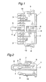
- Figs. 1 and 2 are a plan view and a cross sectional view, respectively showing a rear holder 1 of a first embodiment of the electrical connector according to the present invention.
- the rear holder 1 comprises a rear holder main body 2 including a plurality of resilient clamping lances 3 which protrude forwardly such that each clamping lances are inserted into respective one of a plurality of terminal receiving holes formed in a housing main body to clamp respective connection terminals.
- a resilient locking arm 4 which is formed in U-shape having a folded portion situating forwardly.
- An upper arm 5 of the locking arm 4 extends backwardly and has a locking claw 6 formed thereon.
- a lock releasing portion 7 which is connected to the rear holder main body 2 by means of a resilient arm 8.
- a reference numeral 9 denotes a completely engaging claw and a reference numeral 10 shows a preliminarily engaging claw.
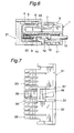
- Fig. 3 is a cross sectional view showing a first connector, in which the rear holder 1 has been inserted into a housing main body 11 from a backside and has been clamped therein.
- the housing main body 11 In the housing main body 11, there are formed two rows of terminal receiving holes 12, the upper row including eight holes and the lower row containing nine holes.
- a female connector terminal 14 having an electric wire 13 connected thereto is inserted into the terminal receiving hole 12 such that a front end of the connector terminal 14 is urged against a stopper portion 15, and therefore the connector terminal 14 could not be moved forwardly any more.
- the locking lance 3 is inserted into the terminal receiving hole 12 such that the locking lance 3 is urged against a rear edge of a connecting portion of the connection terminal 14.
- Fig. 4 is a cross sectional view showing a front end portion of a housing main body 21 of a cooperating connector which is to be coupled with the first connector, while a rear portion of the housing main body 21 is not shown in the drawing.
- the housing main body 21 has installed therein a plurality of male type connection terminals 22 each of which is to be connected to respective one of the female type connection terminals 14 installed in the housing main body 11 of the first connector.
- a locking portion 23 which is to be engaged with the locking claw 6 of the rear holder 1.
- Fig. 5 is a cross sectional view illustrating a condition in which the first and second connectors are engaged with each other.
- the housing main body 11 is inserted into the cooperating housing main body 21 and the connection terminals 14 and 22 are engaged with each other to establish the electrical connection.
- the locking arm 4 of the rear holder 1 is resiliently bent downward to pass under the locking portion 23 of the housing main body 21, and then the locking arm 4 is returned into the original posture and a locking claw 6 at the locking arm 4 is engaged with the locking portion 23 to establish the locking.
- the rear holder 1 and housing main body 21 of the second connector are locked, while the housing main body 11 of the first connector is clamped between the rear holder 1 and the housing main body 21.
- the lock releasing portion 7 provided at a free end of the locking arm 4 is pushed downward as illustrated in Fig. 6 by a finger to move the locking arm 4 downward and the locking claw 6 is removed from the locking portion 23. Then, the housing main body 11 may be drawn from the housing main body 21.
- Figs. 7 and 8 are a plan view and a cross sectional view, respectively depicting a second embodiment of the rear holder 31.
- a rear holder main body 32 has formed therein clamping lances 33 and a locking arm 34 whose free end extends forwardly, and a locking claw 35 is formed at the free end of the locking arm 34.
- a lock releasing portion 36 which is coupled with the rear holder main body 32 via a resilient arm 37.
- Fig. 9 is a cross sectional view showing a condition in which connection terminals 14 are installed in a housing main body 41 and the rear holder 31 has been inserted into the housing main body 41. Connecting portions of the female type connection terminals 14 inserted into terminal receiving holes 42 are clamped by the clamping lances 33 of the rear holder 31. In the housing main body 41, there is provided a subsidiary arm 43 for reinforcing the resilient force of the locking arm 34 by pushing the locking arm 34 upwardly.
- the complete or final engagement of the rear holder 31 is attained via the preliminary engagement, but preliminarily engaging claw and completely engaging claw provided on the rear holder 31 are not shown in the drawings.
- Fig. 10 is a longitudinal cross sectional view illustrating a condition in which the housing main body 41 of the first connector and the housing main body 21 of the second connector have been coupled with each other.
- the locking claw 35 of the locking arm 34 provided on the rear holder 31 have been engaged with the locking portion 23 of the housing main body 21 of the second connector, and the rear holder 31 and housing main body 21 are locked with each other.
- Fig. 11 depicts a condition in which the locking is released by pushing the lock releasing portion 36 downward to move the locking arm 34 downward against the force of the subsidiary arm 43.
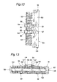
- Figs. 12, 13 and 14 are a plan view, front view and an enlarged side view, respectively showing a rear holder 51 of a third embodiment of the electrical connector according to the invention.
- a rear holder main body 52 of the rear holder 51 there are formed a plurality of clamping lances 53.
- At a middle upper portion of the rear holder main body 52 there are formed two resilient locking arms 54 which extend forwardly.
- Locking claws 55 are provided at front ends of these locking arms 54, interlocking portions 56 are provided on sides of these locking arms 54, and lock releasing portions 57 are provided on upper surfaces of root portions of these locking arms 54.
- On both sides of the rear holder main body 52 there are formed completely engaging claws 58, and on top and bottom surfaces of the rear holder main body 52 there are formed preliminarily engaging claws 59.
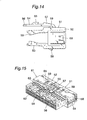
- Figs. 15, 16 and 17 are a perspective view, plan view and an enlarged cross sectional view, respectively showing a condition in which the rear holder 51 has been inserted halfway into a housing main body 61 of a first connector into a preliminarily engaged position.
- Within the housing main body 61 there are formed two rows of terminal receiving holes 62 such that each of the upper and lower rows includes twenty holes.
- On an upper surface of the housing main body 61 there are formed interlocking portions 63 which are to be coupled with the interlocking portions 56 formed on the locking arms 54 of the rear holder 51, said interlocking portions serving to restrict an upward movement of the locking arms 54.
- elongated recesses 64 which cooperate with the completely engaging claws 58 of the rear holder 51
- elongated recesses 65 which cooperate with the preliminarily engaging claws 59 of the rear holder 51.
- Figs. 18, 19 and 20 are a perspective view, a plan view and an enlarged cross sectional view, respectively showing a completely engaged condition.
- the rear holder 51 is further pushed forwardly into the housing main body 61 into the completely engaged position.
- rear edges of the connecting portions 67a are pushed by the clamping lances 53 and are inserted into front ends of the terminal receiving holes 62. Since the connection terminals 67 are urged against the inner walls of the terminal receiving holes 62, the connection terminals could not be drawn forwardly.
- the interlocking portions 56 of the locking arms 54 are engaged with the interlocking portions 63 formed on the housing main body 61, and therefore undesired upward movement of the locking arms 54 can be prevented.
- Fig. 21 is a cross sectional view illustrating a condition, in which the housing main body 61 of the first connector has been engaged with a housing main body 71 of a cooperating second connector.
- the housing main body 71 has installed therein a plurality of male type connection terminals 72 each of which is connected to respective one of the female type connection terminals 67 installed in the housing main body 61 of the first connector.
- In the housing main body 71 there are formed locking portions 73 which are engaged with the locking claws 55' of the locking arms 54 of the rear holder 51.
- the housing main body 61 of the first connector has been inserted into the housing main body 71 of the cooperating second connector and the connection terminals 67 and 72 have been engaged with each other to establish the electrical connection.
- the locking arms 54 of the rear holder 51 is resiliently bent downward to pass under the locking portions 73 of the housing main body 71, and then the locking arm 54 is returned into the original posture and locking claws 55 at the locking arms 54 are engaged with the locking portions 73 to establish the locking. In this manner, the rear holder 51 and housing main body 71 of the second connector are locked with each other effectively.
- the lock releasing portion 57 provided on the locking arms 54 are pushed downward by fingers to move the locking arms 54 downward and the locking claws 55 are removed from the locking portions 73. Then, the housing main body 61 of the first connector may be drawn from the housing main body 71 of the second connector.
- the rear holder 1, 31, 51 provided in the housing main body 11, 41, 61 of the first connector is locked with the housing main body 21, 71 of the second cooperating connector, but according to the invention, the rear holder may be locked with a rear holder provided at a rear portion of the housing main body of the cooperating second connector.
- the two housing main bodies could not be separated from each other and the rear holder could not be removed from the housing main body of the first connector.
- a height of the housing can be reduced as compared with a case in which the locking mechanism is provided on the housing main bodies. Since the housing main body of the first connector is clamped between the rear holder and the housing main body of the second connector, undesired play of the connection terminals installed within the housing main body of the first connector can be reduced.
- the rear holder could not be coupled with the second connector as long as the rear holder has not been completely inserted into the housing main body of the first connector, a user can know an incomplete insertion of the rear holder into the housing main body of the first connector.
Landscapes
- Connector Housings Or Holding Contact Members (AREA)
- Details Of Connecting Devices For Male And Female Coupling (AREA)
Applications Claiming Priority (3)
| Application Number | Priority Date | Filing Date | Title |
|---|---|---|---|
| JP2003003995 | 2003-01-10 | ||
| JP2003003995A JP4047731B2 (ja) | 2003-01-10 | 2003-01-10 | 電気コネクタ |
| PCT/JP2003/011305 WO2004064200A1 (fr) | 2003-01-10 | 2003-09-04 | Connecteur electrique |
Publications (3)
| Publication Number | Publication Date |
|---|---|
| EP1583182A1 true EP1583182A1 (fr) | 2005-10-05 |
| EP1583182A4 EP1583182A4 (fr) | 2007-08-29 |
| EP1583182B1 EP1583182B1 (fr) | 2012-02-15 |
Family
ID=32708934
Family Applications (1)
| Application Number | Title | Priority Date | Filing Date |
|---|---|---|---|
| EP03815139A Expired - Lifetime EP1583182B1 (fr) | 2003-01-10 | 2003-09-04 | Connecteur electrique |
Country Status (8)
| Country | Link |
|---|---|
| US (1) | US7393233B2 (fr) |
| EP (1) | EP1583182B1 (fr) |
| JP (1) | JP4047731B2 (fr) |
| KR (1) | KR101030154B1 (fr) |
| CN (1) | CN100477402C (fr) |
| AT (1) | ATE545972T1 (fr) |
| BR (1) | BR0317357A (fr) |
| WO (1) | WO2004064200A1 (fr) |
Families Citing this family (15)
| Publication number | Priority date | Publication date | Assignee | Title |
|---|---|---|---|---|
| KR101143202B1 (ko) * | 2003-06-18 | 2012-05-18 | 에프씨아이 아시아 테크놀로지 피티이 리미티드 | 전기 커넥터 |
| JP4168104B2 (ja) | 2006-09-21 | 2008-10-22 | 日本航空電子工業株式会社 | コネクタ |
| KR100838786B1 (ko) * | 2006-12-14 | 2008-06-19 | 한국단자공업 주식회사 | 커넥터하우징 |
| JP2008287898A (ja) * | 2007-05-15 | 2008-11-27 | Mitsubishi Cable Ind Ltd | コネクタ |
| KR100982943B1 (ko) * | 2008-06-12 | 2010-09-17 | 한국단자공업 주식회사 | 부품체결장치 및 이를 포함하는 커넥터조립체 |
| DE102011002135B4 (de) * | 2011-04-18 | 2012-12-13 | Tyco Electronics Amp Gmbh | Steckerelement mit zweiter Kontaktsicherung |
| JP5776468B2 (ja) * | 2011-09-22 | 2015-09-09 | 住友電装株式会社 | コネクタ |
| JP6138428B2 (ja) * | 2012-05-29 | 2017-05-31 | 矢崎総業株式会社 | コネクタ |
| US20150214663A1 (en) * | 2014-01-29 | 2015-07-30 | Hyundai Motor Company | Connector assembly for vehicle |
| JP6286385B2 (ja) * | 2015-04-10 | 2018-02-28 | 矢崎総業株式会社 | コネクタ |
| WO2018003466A1 (fr) * | 2016-06-29 | 2018-01-04 | 株式会社オートネットワーク技術研究所 | Module de borne et connecteur |
| US9876312B1 (en) * | 2017-04-06 | 2018-01-23 | Amphenol East Asia Electronic Technology (Shen Zhen) Co., Ltd. | Double locking mechanism between plate end and cable end of ethernet vehicle connector |
| WO2019131264A1 (fr) * | 2017-12-26 | 2019-07-04 | 住友電装株式会社 | Connecteur |
| US10186803B1 (en) | 2018-04-05 | 2019-01-22 | Delphi Technologies, Llc | Electrical connector with connector lock |
| US20220393402A1 (en) * | 2021-06-03 | 2022-12-08 | Molex, Llc | First electrical connector, second electrical connector and electrical connector assembly |
Citations (2)
| Publication number | Priority date | Publication date | Assignee | Title |
|---|---|---|---|---|
| EP0189979A1 (fr) * | 1985-01-28 | 1986-08-06 | General Motors Corporation | Connecteur électrique |
| EP0519815A1 (fr) * | 1991-06-21 | 1992-12-23 | Labinal | Connecteur électrique |
Family Cites Families (7)
| Publication number | Priority date | Publication date | Assignee | Title |
|---|---|---|---|---|
| JP2849897B2 (ja) * | 1993-12-01 | 1999-01-27 | 矢崎総業株式会社 | 簡易防水コネクタ |
| JP3064176B2 (ja) * | 1994-03-08 | 2000-07-12 | 矢崎総業株式会社 | コネクタのロック解除構造 |
| JP3556879B2 (ja) * | 2000-03-15 | 2004-08-25 | 住友電装株式会社 | コネクタ |
| JP3752982B2 (ja) * | 2000-08-29 | 2006-03-08 | 住友電装株式会社 | 防水コネクタ |
| JP2002252063A (ja) * | 2001-02-26 | 2002-09-06 | Jst Mfg Co Ltd | ロック機構付コネクタ・アセンブリー |
| JP3999535B2 (ja) * | 2002-03-04 | 2007-10-31 | 三菱電線工業株式会社 | 電気コネクタ |
| JP3714278B2 (ja) * | 2002-05-07 | 2005-11-09 | 住友電装株式会社 | コネクタハウジング |
-
2003
- 2003-01-10 JP JP2003003995A patent/JP4047731B2/ja not_active Expired - Fee Related
- 2003-09-04 AT AT03815139T patent/ATE545972T1/de active
- 2003-09-04 CN CNB038257793A patent/CN100477402C/zh not_active Expired - Fee Related
- 2003-09-04 EP EP03815139A patent/EP1583182B1/fr not_active Expired - Lifetime
- 2003-09-04 US US10/541,519 patent/US7393233B2/en not_active Expired - Fee Related
- 2003-09-04 WO PCT/JP2003/011305 patent/WO2004064200A1/fr active Application Filing
- 2003-09-04 BR BR0317357-7A patent/BR0317357A/pt not_active IP Right Cessation
- 2003-09-04 KR KR1020057012802A patent/KR101030154B1/ko active IP Right Grant
Patent Citations (2)
| Publication number | Priority date | Publication date | Assignee | Title |
|---|---|---|---|---|
| EP0189979A1 (fr) * | 1985-01-28 | 1986-08-06 | General Motors Corporation | Connecteur électrique |
| EP0519815A1 (fr) * | 1991-06-21 | 1992-12-23 | Labinal | Connecteur électrique |
Non-Patent Citations (1)
| Title |
|---|
| See also references of WO2004064200A1 * |
Also Published As
| Publication number | Publication date |
|---|---|
| WO2004064200A1 (fr) | 2004-07-29 |
| BR0317357A (pt) | 2005-11-08 |
| ATE545972T1 (de) | 2012-03-15 |
| US7393233B2 (en) | 2008-07-01 |
| JP4047731B2 (ja) | 2008-02-13 |
| CN1720645A (zh) | 2006-01-11 |
| US20060160433A1 (en) | 2006-07-20 |
| KR20050107740A (ko) | 2005-11-15 |
| JP2004220824A (ja) | 2004-08-05 |
| CN100477402C (zh) | 2009-04-08 |
| EP1583182A4 (fr) | 2007-08-29 |
| EP1583182B1 (fr) | 2012-02-15 |
| KR101030154B1 (ko) | 2011-04-18 |
Similar Documents
| Publication | Publication Date | Title |
|---|---|---|
| JP6664425B2 (ja) | 端子位置保証装置を有する電気コネクタ | |
| US7252556B2 (en) | Electrical connector having locking claw | |
| EP1560298B1 (fr) | Connecteur cloisonné et montage de connecteurs | |
| JP3596729B2 (ja) | コネクタ嵌合構造 | |
| JP3467202B2 (ja) | コネクタのロック機構 | |
| EP1583182B1 (fr) | Connecteur electrique | |
| US9698514B2 (en) | Connector | |
| JP3553805B2 (ja) | コネクタ嵌合構造 | |
| US7114997B2 (en) | Electrical connector | |
| JP2522324Y2 (ja) | コネクタ | |
| EP1635425B1 (fr) | Terminal de connexion | |
| EP1005111A2 (fr) | Connecteur | |
| JP7251398B2 (ja) | コネクタ | |
| EP1548894B1 (fr) | Connecteur | |
| JP3763422B2 (ja) | コネクタ | |
| JP3101203B2 (ja) | リテーナを有する電気コネクタ | |
| US6334790B2 (en) | Electrical connection and housing having a lance in a terminal accommodation chamber | |
| US5928014A (en) | Electrical connector having a pair of connector housings | |
| JPH09289059A (ja) | コネクタ | |
| US6488547B2 (en) | Connector with longitudinally spaced locks for retaining terminal fittings | |
| JPH1055843A (ja) | コネクタ、ターミナル及びターミナル係止解除治具 | |
| JP3999535B2 (ja) | 電気コネクタ | |
| JP3449909B2 (ja) | コネクタ | |
| JP2021022475A (ja) | コネクタ | |
| JP2004241313A (ja) | 電気コネクタ |
Legal Events
| Date | Code | Title | Description |
|---|---|---|---|
| PUAI | Public reference made under article 153(3) epc to a published international application that has entered the european phase |
Free format text: ORIGINAL CODE: 0009012 |
|
| 17P | Request for examination filed |
Effective date: 20050704 |
|
| AK | Designated contracting states |
Kind code of ref document: A1 Designated state(s): AT BE BG CH CY CZ DE DK EE ES FI FR GB GR HU IE IT LI LU MC NL PT SE SI SK TR |
|
| A4 | Supplementary search report drawn up and despatched |
Effective date: 20070801 |
|
| RAP1 | Party data changed (applicant data changed or rights of an application transferred) |
Owner name: RYOSEI ELECTRO-CIRCUIT SYSTEMS, LTD. Owner name: FCI |
|
| 17Q | First examination report despatched |
Effective date: 20100802 |
|
| RAP1 | Party data changed (applicant data changed or rights of an application transferred) |
Owner name: FCI Owner name: RYOSEI ELECTRO-CIRCUIT SYSTEMS, LTD. |
|
| RAP1 | Party data changed (applicant data changed or rights of an application transferred) |
Owner name: RYOSEI ELECTRO-CIRCUIT SYSTEMS, LTD. Owner name: FCI AUTOMOTIVE HOLDING |
|
| GRAP | Despatch of communication of intention to grant a patent |
Free format text: ORIGINAL CODE: EPIDOSNIGR1 |
|
| RBV | Designated contracting states (corrected) |
Designated state(s): AT BE BG CH CY CZ DE DK EE ES FI FR GB GR HU IE IT LI LU MC NL PT RO SE SI SK TR |
|
| GRAS | Grant fee paid |
Free format text: ORIGINAL CODE: EPIDOSNIGR3 |
|
| GRAA | (expected) grant |
Free format text: ORIGINAL CODE: 0009210 |
|
| RAP1 | Party data changed (applicant data changed or rights of an application transferred) |
Owner name: FCI AUTOMOTIVE HOLDING Owner name: MITSUBISHI CABLE INDUSTRIES, LTD. |
|
| AK | Designated contracting states |
Kind code of ref document: B1 Designated state(s): AT BE BG CH CY CZ DE DK EE ES FI FR GB GR HU IE IT LI LU MC NL PT RO SE SI SK TR |
|
| REG | Reference to a national code |
Ref country code: CH Ref legal event code: EP Ref country code: GB Ref legal event code: FG4D |
|
| REG | Reference to a national code |
Ref country code: IE Ref legal event code: FG4D |
|
| REG | Reference to a national code |
Ref country code: AT Ref legal event code: REF Ref document number: 545972 Country of ref document: AT Kind code of ref document: T Effective date: 20120315 |
|
| REG | Reference to a national code |
Ref country code: DE Ref legal event code: R096 Ref document number: 60340031 Country of ref document: DE Effective date: 20120412 |
|
| REG | Reference to a national code |
Ref country code: NL Ref legal event code: VDEP Effective date: 20120215 |
|
| PG25 | Lapsed in a contracting state [announced via postgrant information from national office to epo] |
Ref country code: NL Free format text: LAPSE BECAUSE OF FAILURE TO SUBMIT A TRANSLATION OF THE DESCRIPTION OR TO PAY THE FEE WITHIN THE PRESCRIBED TIME-LIMIT Effective date: 20120215 |
|
| PG25 | Lapsed in a contracting state [announced via postgrant information from national office to epo] |
Ref country code: BE Free format text: LAPSE BECAUSE OF FAILURE TO SUBMIT A TRANSLATION OF THE DESCRIPTION OR TO PAY THE FEE WITHIN THE PRESCRIBED TIME-LIMIT Effective date: 20120215 Ref country code: PT Free format text: LAPSE BECAUSE OF FAILURE TO SUBMIT A TRANSLATION OF THE DESCRIPTION OR TO PAY THE FEE WITHIN THE PRESCRIBED TIME-LIMIT Effective date: 20120615 Ref country code: GR Free format text: LAPSE BECAUSE OF FAILURE TO SUBMIT A TRANSLATION OF THE DESCRIPTION OR TO PAY THE FEE WITHIN THE PRESCRIBED TIME-LIMIT Effective date: 20120516 Ref country code: FI Free format text: LAPSE BECAUSE OF FAILURE TO SUBMIT A TRANSLATION OF THE DESCRIPTION OR TO PAY THE FEE WITHIN THE PRESCRIBED TIME-LIMIT Effective date: 20120215 |
|
| REG | Reference to a national code |
Ref country code: AT Ref legal event code: MK05 Ref document number: 545972 Country of ref document: AT Kind code of ref document: T Effective date: 20120215 |
|
| PG25 | Lapsed in a contracting state [announced via postgrant information from national office to epo] |
Ref country code: CY Free format text: LAPSE BECAUSE OF FAILURE TO SUBMIT A TRANSLATION OF THE DESCRIPTION OR TO PAY THE FEE WITHIN THE PRESCRIBED TIME-LIMIT Effective date: 20120215 |
|
| PG25 | Lapsed in a contracting state [announced via postgrant information from national office to epo] |
Ref country code: SE Free format text: LAPSE BECAUSE OF FAILURE TO SUBMIT A TRANSLATION OF THE DESCRIPTION OR TO PAY THE FEE WITHIN THE PRESCRIBED TIME-LIMIT Effective date: 20120215 Ref country code: CZ Free format text: LAPSE BECAUSE OF FAILURE TO SUBMIT A TRANSLATION OF THE DESCRIPTION OR TO PAY THE FEE WITHIN THE PRESCRIBED TIME-LIMIT Effective date: 20120215 Ref country code: RO Free format text: LAPSE BECAUSE OF FAILURE TO SUBMIT A TRANSLATION OF THE DESCRIPTION OR TO PAY THE FEE WITHIN THE PRESCRIBED TIME-LIMIT Effective date: 20120215 Ref country code: SI Free format text: LAPSE BECAUSE OF FAILURE TO SUBMIT A TRANSLATION OF THE DESCRIPTION OR TO PAY THE FEE WITHIN THE PRESCRIBED TIME-LIMIT Effective date: 20120215 Ref country code: DK Free format text: LAPSE BECAUSE OF FAILURE TO SUBMIT A TRANSLATION OF THE DESCRIPTION OR TO PAY THE FEE WITHIN THE PRESCRIBED TIME-LIMIT Effective date: 20120215 Ref country code: EE Free format text: LAPSE BECAUSE OF FAILURE TO SUBMIT A TRANSLATION OF THE DESCRIPTION OR TO PAY THE FEE WITHIN THE PRESCRIBED TIME-LIMIT Effective date: 20120215 |
|
| PG25 | Lapsed in a contracting state [announced via postgrant information from national office to epo] |
Ref country code: SK Free format text: LAPSE BECAUSE OF FAILURE TO SUBMIT A TRANSLATION OF THE DESCRIPTION OR TO PAY THE FEE WITHIN THE PRESCRIBED TIME-LIMIT Effective date: 20120215 |
|
| PLBE | No opposition filed within time limit |
Free format text: ORIGINAL CODE: 0009261 |
|
| STAA | Information on the status of an ep patent application or granted ep patent |
Free format text: STATUS: NO OPPOSITION FILED WITHIN TIME LIMIT |
|
| 26N | No opposition filed |
Effective date: 20121116 |
|
| PG25 | Lapsed in a contracting state [announced via postgrant information from national office to epo] |
Ref country code: AT Free format text: LAPSE BECAUSE OF FAILURE TO SUBMIT A TRANSLATION OF THE DESCRIPTION OR TO PAY THE FEE WITHIN THE PRESCRIBED TIME-LIMIT Effective date: 20120215 |
|
| REG | Reference to a national code |
Ref country code: DE Ref legal event code: R097 Ref document number: 60340031 Country of ref document: DE Effective date: 20121116 |
|
| PG25 | Lapsed in a contracting state [announced via postgrant information from national office to epo] |
Ref country code: ES Free format text: LAPSE BECAUSE OF FAILURE TO SUBMIT A TRANSLATION OF THE DESCRIPTION OR TO PAY THE FEE WITHIN THE PRESCRIBED TIME-LIMIT Effective date: 20120526 Ref country code: MC Free format text: LAPSE BECAUSE OF NON-PAYMENT OF DUE FEES Effective date: 20120930 |
|
| REG | Reference to a national code |
Ref country code: CH Ref legal event code: PL |
|
| REG | Reference to a national code |
Ref country code: IE Ref legal event code: MM4A |
|
| PG25 | Lapsed in a contracting state [announced via postgrant information from national office to epo] |
Ref country code: IE Free format text: LAPSE BECAUSE OF NON-PAYMENT OF DUE FEES Effective date: 20120904 Ref country code: CH Free format text: LAPSE BECAUSE OF NON-PAYMENT OF DUE FEES Effective date: 20120930 Ref country code: LI Free format text: LAPSE BECAUSE OF NON-PAYMENT OF DUE FEES Effective date: 20120930 Ref country code: BG Free format text: LAPSE BECAUSE OF FAILURE TO SUBMIT A TRANSLATION OF THE DESCRIPTION OR TO PAY THE FEE WITHIN THE PRESCRIBED TIME-LIMIT Effective date: 20120515 |
|
| PG25 | Lapsed in a contracting state [announced via postgrant information from national office to epo] |
Ref country code: IT Free format text: LAPSE BECAUSE OF NON-PAYMENT OF DUE FEES Effective date: 20120904 |
|
| REG | Reference to a national code |
Ref country code: FR Ref legal event code: TQ Owner name: FCI AUTOMOTIVE HOLDING, FR Effective date: 20131223 Ref country code: FR Ref legal event code: TQ Owner name: FURUKAWA AUTOMOTIVE SYSTEMS INC., JP Effective date: 20131223 Ref country code: FR Ref legal event code: TQ Owner name: THE FURUKAWA ELECTRIC CO., LTD., JP Effective date: 20131223 |
|
| PG25 | Lapsed in a contracting state [announced via postgrant information from national office to epo] |
Ref country code: TR Free format text: LAPSE BECAUSE OF FAILURE TO SUBMIT A TRANSLATION OF THE DESCRIPTION OR TO PAY THE FEE WITHIN THE PRESCRIBED TIME-LIMIT Effective date: 20120215 |
|
| PG25 | Lapsed in a contracting state [announced via postgrant information from national office to epo] |
Ref country code: LU Free format text: LAPSE BECAUSE OF NON-PAYMENT OF DUE FEES Effective date: 20120904 |
|
| REG | Reference to a national code |
Ref country code: DE Ref legal event code: R081 Ref document number: 60340031 Country of ref document: DE Owner name: FCI AUTOMOTIVE HOLDING, FR Free format text: FORMER OWNER: RYOSEI ELECTRO-CIRCUIT SYSTEMS,, FCI ASIA TECHNOLOGY PTE LTD., , SG Effective date: 20120216 Ref country code: DE Ref legal event code: R081 Ref document number: 60340031 Country of ref document: DE Owner name: FURUKAWA AUTOMOTIVE SYSTEMS INC., JP Free format text: FORMER OWNER: RYOSEI ELECTRO-CIRCUIT SYSTEMS,, FCI ASIA TECHNOLOGY PTE LTD., , SG Effective date: 20120216 Ref country code: DE Ref legal event code: R081 Ref document number: 60340031 Country of ref document: DE Owner name: FURUKAWA ELECTRIC CO. LTD, JP Free format text: FORMER OWNER: FCI AUTOMOTIVE HOLDING, MITSUBISHI CABLE INDUSTRIES, LT, , JP Effective date: 20140603 Ref country code: DE Ref legal event code: R081 Ref document number: 60340031 Country of ref document: DE Owner name: FURUKAWA AUTOMOTIVE SYSTEMS INC., JP Free format text: FORMER OWNER: FCI AUTOMOTIVE HOLDING, MITSUBISHI CABLE INDUSTRIES, LT, , JP Effective date: 20140603 Ref country code: DE Ref legal event code: R081 Ref document number: 60340031 Country of ref document: DE Owner name: FURUKAWA ELECTRIC CO. LTD, JP Free format text: FORMER OWNER: RYOSEI ELECTRO-CIRCUIT SYSTEMS,, FCI ASIA TECHNOLOGY PTE LTD., , SG Effective date: 20120216 Ref country code: DE Ref legal event code: R081 Ref document number: 60340031 Country of ref document: DE Owner name: FCI AUTOMOTIVE HOLDING, FR Free format text: FORMER OWNER: FCI AUTOMOTIVE HOLDING, MITSUBISHI CABLE INDUSTRIES, LT, , JP Effective date: 20140603 Ref country code: DE Ref legal event code: R081 Ref document number: 60340031 Country of ref document: DE Owner name: DELPHI INTERNATIONAL OPERATIONS LUXEMBOURG S.A, LU Free format text: FORMER OWNER: RYOSEI ELECTRO-CIRCUIT SYSTEMS,, FCI ASIA TECHNOLOGY PTE LTD., , SG Effective date: 20120216 Ref country code: DE Ref legal event code: R081 Ref document number: 60340031 Country of ref document: DE Owner name: DELPHI INTERNATIONAL OPERATIONS LUXEMBOURG S.A, LU Free format text: FORMER OWNER: FCI AUTOMOTIVE HOLDING, MITSUBISHI CABLE INDUSTRIES, LT, , JP Effective date: 20140603 Ref country code: DE Ref legal event code: R081 Ref document number: 60340031 Country of ref document: DE Owner name: DELPHI INTERNATIONAL OPERATIONS LUXEMBOURG S.A, LU Free format text: FORMER OWNERS: FCI AUTOMOTIVE HOLDING, GUYANCOURT, FR; MITSUBISHI CABLE INDUSTRIES, LTD., TOKYO, CHIYODA-KU, JP Effective date: 20140603 Ref country code: DE Ref legal event code: R081 Ref document number: 60340031 Country of ref document: DE Owner name: FURUKAWA AUTOMOTIVE SYSTEMS INC., JP Free format text: FORMER OWNERS: FCI AUTOMOTIVE HOLDING, GUYANCOURT, FR; MITSUBISHI CABLE INDUSTRIES, LTD., TOKYO, CHIYODA-KU, JP Effective date: 20140603 Ref country code: DE Ref legal event code: R081 Ref document number: 60340031 Country of ref document: DE Owner name: FURUKAWA ELECTRIC CO. LTD, JP Free format text: FORMER OWNERS: FCI AUTOMOTIVE HOLDING, GUYANCOURT, FR; MITSUBISHI CABLE INDUSTRIES, LTD., TOKYO, CHIYODA-KU, JP Effective date: 20140603 Ref country code: DE Ref legal event code: R081 Ref document number: 60340031 Country of ref document: DE Owner name: FURUKAWA AUTOMOTIVE SYSTEMS INC., JP Free format text: FORMER OWNERS: RYOSEI ELECTRO-CIRCUIT SYSTEMS, LTD., TOKIO/TOKYO, JP; FCI ASIA TECHNOLOGY PTE LTD., NGEE ANN CITY, SG Effective date: 20120216 Ref country code: DE Ref legal event code: R081 Ref document number: 60340031 Country of ref document: DE Owner name: FURUKAWA ELECTRIC CO. LTD, JP Free format text: FORMER OWNERS: RYOSEI ELECTRO-CIRCUIT SYSTEMS, LTD., TOKIO/TOKYO, JP; FCI ASIA TECHNOLOGY PTE LTD., NGEE ANN CITY, SG Effective date: 20120216 Ref country code: DE Ref legal event code: R081 Ref document number: 60340031 Country of ref document: DE Owner name: DELPHI INTERNATIONAL OPERATIONS LUXEMBOURG S.A, LU Free format text: FORMER OWNERS: RYOSEI ELECTRO-CIRCUIT SYSTEMS, LTD., TOKIO/TOKYO, JP; FCI ASIA TECHNOLOGY PTE LTD., NGEE ANN CITY, SG Effective date: 20120216 |
|
| PG25 | Lapsed in a contracting state [announced via postgrant information from national office to epo] |
Ref country code: HU Free format text: LAPSE BECAUSE OF FAILURE TO SUBMIT A TRANSLATION OF THE DESCRIPTION OR TO PAY THE FEE WITHIN THE PRESCRIBED TIME-LIMIT Effective date: 20030904 |
|
| REG | Reference to a national code |
Ref country code: FR Ref legal event code: TQ Owner name: FURUKAWA AUTOMOTIVE SYSTEMS INC., JP Effective date: 20140715 Ref country code: FR Ref legal event code: TQ Owner name: THE FURUKAWA ELECTRIC CO., LTD., JP Effective date: 20140715 Ref country code: FR Ref legal event code: TQ Owner name: DELPHI INTERNATIONAL OPERATIONS LUXEMBOURG S.A, LU Effective date: 20140715 |
|
| REG | Reference to a national code |
Ref country code: DE Ref legal event code: R081 Ref document number: 60340031 Country of ref document: DE Owner name: FURUKAWA AUTOMOTIVE SYSTEMS INC., JP Free format text: FORMER OWNER: FCI AUTOMOTIVE HOLDING, FURUKAWA AUTOMOTIVE SYSTEMS INC, FURUKAWA ELECTRIC CO. LTD, , JP Effective date: 20141106 Ref country code: DE Ref legal event code: R081 Ref document number: 60340031 Country of ref document: DE Owner name: DELPHI INTERNATIONAL OPERATIONS LUXEMBOURG S.A, LU Free format text: FORMER OWNER: FCI AUTOMOTIVE HOLDING, FURUKAWA AUTOMOTIVE SYSTEMS INC, FURUKAWA ELECTRIC CO. LTD, , JP Effective date: 20141106 Ref country code: DE Ref legal event code: R081 Ref document number: 60340031 Country of ref document: DE Owner name: FURUKAWA ELECTRIC CO. LTD, JP Free format text: FORMER OWNER: FCI AUTOMOTIVE HOLDING, FURUKAWA AUTOMOTIVE SYSTEMS INC, FURUKAWA ELECTRIC CO. LTD, , JP Effective date: 20141106 Ref country code: DE Ref legal event code: R081 Ref document number: 60340031 Country of ref document: DE Owner name: FURUKAWA ELECTRIC CO. LTD, JP Free format text: FORMER OWNERS: FCI AUTOMOTIVE HOLDING, GUYANCOURT, FR; FURUKAWA AUTOMOTIVE SYSTEMS INC., SHIGA, JP; FURUKAWA ELECTRIC CO. LTD, TOKIO/TOKYO, JP Effective date: 20141106 Ref country code: DE Ref legal event code: R081 Ref document number: 60340031 Country of ref document: DE Owner name: FURUKAWA AUTOMOTIVE SYSTEMS INC., JP Free format text: FORMER OWNERS: FCI AUTOMOTIVE HOLDING, GUYANCOURT, FR; FURUKAWA AUTOMOTIVE SYSTEMS INC., SHIGA, JP; FURUKAWA ELECTRIC CO. LTD, TOKIO/TOKYO, JP Effective date: 20141106 Ref country code: DE Ref legal event code: R081 Ref document number: 60340031 Country of ref document: DE Owner name: DELPHI INTERNATIONAL OPERATIONS LUXEMBOURG S.A, LU Free format text: FORMER OWNERS: FCI AUTOMOTIVE HOLDING, GUYANCOURT, FR; FURUKAWA AUTOMOTIVE SYSTEMS INC., SHIGA, JP; FURUKAWA ELECTRIC CO. LTD, TOKIO/TOKYO, JP Effective date: 20141106 |
|
| REG | Reference to a national code |
Ref country code: GB Ref legal event code: 732E Free format text: REGISTERED BETWEEN 20141218 AND 20141223 |
|
| REG | Reference to a national code |
Ref country code: FR Ref legal event code: PLFP Year of fee payment: 13 |
|
| PGFP | Annual fee paid to national office [announced via postgrant information from national office to epo] |
Ref country code: GB Payment date: 20150928 Year of fee payment: 13 |
|
| PGFP | Annual fee paid to national office [announced via postgrant information from national office to epo] |
Ref country code: FR Payment date: 20150917 Year of fee payment: 13 |
|
| PGFP | Annual fee paid to national office [announced via postgrant information from national office to epo] |
Ref country code: DE Payment date: 20150929 Year of fee payment: 13 |
|
| REG | Reference to a national code |
Ref country code: DE Ref legal event code: R119 Ref document number: 60340031 Country of ref document: DE |
|
| GBPC | Gb: european patent ceased through non-payment of renewal fee |
Effective date: 20160904 |
|
| REG | Reference to a national code |
Ref country code: FR Ref legal event code: ST Effective date: 20170531 |
|
| PG25 | Lapsed in a contracting state [announced via postgrant information from national office to epo] |
Ref country code: DE Free format text: LAPSE BECAUSE OF NON-PAYMENT OF DUE FEES Effective date: 20170401 Ref country code: GB Free format text: LAPSE BECAUSE OF NON-PAYMENT OF DUE FEES Effective date: 20160904 Ref country code: FR Free format text: LAPSE BECAUSE OF NON-PAYMENT OF DUE FEES Effective date: 20160930 |