EP1582165A1 - Behandlungsinstrument mit Wärmeerzeuger - Google Patents
Behandlungsinstrument mit Wärmeerzeuger Download PDFInfo
- Publication number
- EP1582165A1 EP1582165A1 EP05005029A EP05005029A EP1582165A1 EP 1582165 A1 EP1582165 A1 EP 1582165A1 EP 05005029 A EP05005029 A EP 05005029A EP 05005029 A EP05005029 A EP 05005029A EP 1582165 A1 EP1582165 A1 EP 1582165A1
- Authority
- EP
- European Patent Office
- Prior art keywords
- heat
- generating body
- temperature
- power supply
- electric power
- Prior art date
- Legal status (The legal status is an assumption and is not a legal conclusion. Google has not performed a legal analysis and makes no representation as to the accuracy of the status listed.)
- Granted
Links
Images


Classifications
-
- A—HUMAN NECESSITIES
- A61—MEDICAL OR VETERINARY SCIENCE; HYGIENE
- A61B—DIAGNOSIS; SURGERY; IDENTIFICATION
- A61B18/00—Surgical instruments, devices or methods for transferring non-mechanical forms of energy to or from the body
- A61B18/04—Surgical instruments, devices or methods for transferring non-mechanical forms of energy to or from the body by heating
- A61B18/08—Surgical instruments, devices or methods for transferring non-mechanical forms of energy to or from the body by heating by means of electrically-heated probes
- A61B18/082—Probes or electrodes therefor
- A61B18/085—Forceps, scissors
Definitions
- the present invention relates to an operative instrument for heating an anatomy and coagulating or incising the same.
- a known operative instrument heats an anatomy for coagulating or incising the same.
- the known operative instruments include, for example, a heat treatment instrument, a high-frequency treatment instrument, and an ultrasonic treatment instrument.
- the heat treatment instrument heats an anatomy clamped at the extremities of forceps provided with a heat-generating body, such as a heater, for coagulating or incising the same.
- the high-frequency treatment instrument clamps an anatomy between a pair of forceps and supplies a high-frequency current to the anatomy therebetween for heating and thereby coagulating or incising the same.
- the ultrasonic treatment instrument provides ultrasonic vibrations to the extremities of the forceps to generate frictional heat within an anatomy clamped therebetween for coagulating or incising the same.
- heat treatment instrument having a pair of grippers as described in Japanese Patent No. 3349139, or a treatment instrument provided with a heater wire at a working surface of a jaw member as described in WO01/12090 are proposed as the heat treatment instrument.
- the heat coagulation and incision forceps stated in the above-described Patent No. 3349139 is provided with a heat-generating body on one of the grippers to coagulate and incise the gripped anatomy by causing the heat-generating body to generate heat.
- the heat coagulation and incision forceps are controlled to maintain a constant temperature by a power supply unit so that the heat-generating body generates heat to keep the heat-generating body at a constant temperature.
- a power supply unit so that the heat-generating body generates heat to keep the heat-generating body at a constant temperature.
- electric power according to the temperature difference between the heat-generating body and a preset temperature is supplied to the heat-generating body. Since the initial temperature of the heat-generating body is low and hence the temperature difference with respect to the preset temperature is significantly large at the beginning of energization, large electric power is supplied to the heat-generating body to increase the temperature of the heat-generating body rapidly.
- the treatment instrument stated in the above described WO01/12090 employs the heat wire formed of an electric resistor, such as nichrome wire, as the heat-generating body, and is adapted to coagulate and incise the anatomy by heat generated by the heater wire.
- an electric resistor such as nichrome wire
- an operative instrument stated in JP-A-10-286260 is used for treatment of an anatomy by heat generation.
- aerial heat dissipation preventing control is employed for preventing early deterioration of the heat-generating body.
- An operative instrument of the present invention includes a heat-generating body that generates heat to be applied to an anatomy in a treating section for treating the anatomy at an extremity of forceps.
- a power supply unit supplies substantially constant electric power to the heat-generating body from the beginning of heating until the heat-generating body reaches a predetermined temperature. Since the heat-generating body is heated by substantially constant electric power from the beginning until it reaches the predetermined temperature, sufficient electric power for the anatomy to achieve a temperature for incising operation in a short period is supplied also after the anatomy is held at the temperature for the coagulating operation.
- One of the methods for keeping electric power applied to the heat-generating body substantively constant is to keep electric voltage or electric current applied to the heat-generating body constant. Accordingly, even though the value of resistance of the heat-generating body varies to some extent due to rising of the temperature, the electric power applied to the heat-generating body is kept substantially constant.
- One of the methods to keep electric power applied to the heat-generating body substantively constant is to control one or both of the applied electric voltage and the applied electric current to keep the applied electric power constant.
- values of voltage or current at the beginning of application may be determined by energizing the heat-generating body for monitoring at least when application is initiated.
- the value of resistance of the heat-generating body is used for monitoring the temperature.
- the temperature of the heat-generating body can be detected by detecting changes in resistance value with the power supply unit. Accordingly, whether or not the heat-generating body reaches the predetermined temperature can be judged.
- the temperature of the heat-generating body rapidly increases. Therefore, when changes in voltage, current, or value of resistance within a given time period exceed a predetermined value, it is preferable to stop energization of the heat-generating body.
- the heat-generating body After the heat-generating body has reached the predetermined temperature, power supply to the heat-generating body may be stopped. Accordingly, the temperature of the heat-generating body is gradually lowered, but heating is started at a constant electric power by turning a switch on again.
- the constant temperature control for keeping the temperature of the heat-generating body at the preset temperature may be performed.
- the heat-generating body After the heat-generating body has reached the predetermined temperature, the heat-generating body can be energized intermittently. In such intermittent energization, it is further preferable to apply constant voltage, current and electric power. In this arrangement, heat generation of the heat-generating body can be controlled by a duty cycle ratio control mode.
- the supplied electric power is gradually increased to the predetermined electric power for a short time immediately after energization.
- heat distortion of the heat-generating body is decreased, thereby improving durability of the operative instrument.
- the heat-generating body is a heat-generating element having a thin film resistance or a thick film resistance having a temperature coefficient on the surface formed as a heat-generating pattern.
- a change in electric resistance with respect to a change in temperature of its own are larger in comparison with the heater wire such as the nichrome wire. Therefore, the temperature can be detected easily from the resistance, and hence the temperature can be controlled easily.
- Fig. 1 to Fig. 16 relate to a first embodiment of the invention.
- Fig. 1 is a general block diagram showing an operative instrument according to the first embodiment;
- Fig. 2 is a cross-sectional view taken along a line A-A in Fig. 1;
- Fig. 3 is a cross-sectional view showing a modification of Fig. 2;
- Fig. 4 is a drawing viewed in the direction indicated by an arrow B in Fig. 1;
- Fig. 5 is a drawing viewed in the direction indicated by an arrow C in Fig. 1; and
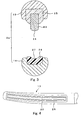
- Fig. 6 is a perspective view of a heat-generating body.
- Fig. 7 is a circuit block diagram of a power supply unit in Fig. 1 and Fig. 8 to Fig.
- Fig. 12 are graphs showing an output control performed by a control circuit in Fig. 7.
- Fig. 8 is a graph showing an output voltage with respect to time.
- Fig. 9 is a graph showing an output current with respect to time;
- Fig. 10 is a graph showing an output electric power with respect to time;
- Fig. 11 is a graph showing an electric resistance of the heat-generating body with respect to time;
- Fig. 12 is a graph showing the temperature of an anatomy with respect to time.
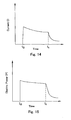
- Fig. 13 to Fig. 16 are graphs showing modifications of the output control.
- Fig. 13 is a graph showing an output voltage with respect to time;
- Fig. 14 is a graph showing an output current with respect to time;
- Fig. 15 is a graph showing an output electric power with respect to time;
- Fig. 16 is a graph showing an electric resistance of the heat-generating body with respect to time.
- an operative instrument 1 of the first embodiment includes forceps 2 that provide heat to an anatomy which they grip to effect coagulating and incising that anatomy.
- a power supply unit 3 that can be disconnectably connected to the forceps 2 outputs electric power of a power source (electric energy) to the forceps 2 to drive and control the same.
- the forceps 2 are adapted in such a manner that a connector (not shown) provided at the rear end of a connecting cord 4 extending therefrom can be disconnectably connected to the power supply unit 3.
- a foot switch 5 can be connected to the power supply unit 3. The operator can turn the power source to the forceps 2 ON and OFF by turning the foot switch 5 ON and OFF.
- a front panel of the power supply unit 3 is provided with a display device for displaying a current value or a voltage value of the power source supplied to the forceps 2 and an operating tab for entering various setting values on a panel input/display unit, described later.
- the forceps 2 mainly include a pair of handles 11, 12 to be held and operated by the operator's hand, a pair of jaws 13, 14 for gripping an anatomy to be treated for coagulation and incision, and a pair of pincers members 15, 16.
- the jaws 13, 14 constitute a treating section 2a of the forceps 2.
- the pair of pincers members 15, 16 extend between the handles 11, 12 and the jaws 13, 14, respectively.
- the pincers members 15, 16 are overlapped substantially in a state of crossing at the midsections thereof. Furthermore, the crossed portion of the pincers members 15, 16 is provided with a pivot pin 17 for rotatably joining the pincers members 15, 16.
- the handles 11, 12 are provided with finger insertion rings 18, 19.
- the forceps 2 are so constructed that back and forth movement of a thumb and an annular finger inserted into the respective rings 18, 19 causes the jaws 13, 14 to open and close correspondingly, so that they can grip, separate, and pressurize the anatomy.
- the pair of handles 11, 12 and the pair of pincers members 15, 16 constitute an operating section 2b of the forceps 2.
- the jaw 13 includes a heat-generating body, described later, embedded therein for providing heat to the anatomy.
- a power supply line 21 for supplying electric power to the heat-generating body is provided within the pincers member 15.
- a heat-generating element having a thin film resistance or a thick film resistance on the surface thereof as a heat-generating pattern is employed, as described later.
- the power supply line 21 extends from the jaw 13 to the handle 11, and is adapted to be electrically connected to the power supply unit 3 from a cord connecting portion 22 on the rear side of the ring 18 via the connecting cord 4 to the power supply unit 3.
- the operative instrument 1 is configured in such a manner that, after the forceps 2 have griped the anatomy via the treating section 2a, electric power is supplied from the power supply unit 3 to the heat-generating body to generate heat, and the heat is provided to the gripped anatomy for coagulation and incision.
- the treating section 2a includes, as shown in Fig. 2, the jaw 13 provided with a heat-generating body 23 for providing heat to the anatomy at a position opposed to the jaw 14.
- the heat-generating body 23 is formed of a material having high heat conductivity, such as copper or molybdenum.
- the heat-generating body 23 is formed with a tissue pressing portion 24 having a relatively dull or coarse shape on the surface facing the jaw 14.
- the upper side of the heat-generating body 23 is covered by a heat-insulating member 25 formed of a material having low heat conductivity and high heat resistance, such as PTFE (polyfluoroethylene, or polytetrafluoroethylene) or PEEK (polyetheretherketone).
- PTFE polyfluoroethylene, or polytetrafluoroethylene
- PEEK polyetheretherketone
- the heat-insulating member 25 is fixed to the jaw 13 by being fitted in a recess of the jaw 13. Accordingly, the heat-generating body 23 provides generated heat efficiently to the anatomy, and prevents the jaw 13 formed of metal material such as stainless from becoming excessively heated.
- the heat-generating body 23 is provided with coating formed of non-adhesive material such as PTFE, not shown, at the contact area with respect to the anatomy for preventing attachment of the anatomy thereto.
- non-adhesive material such as PTFE
- the jaw 14 is integrally provided with a receiving member 26 at the position opposed to the heat-generating body 23.
- the receiving member 26 is formed of resin material such as silicon rubber or PTFE.
- the treating section 2a may have a modified structure as shown in Fig. 3.
- the jaw 13 is formed with the tissue pressing portion 24 of the heat-generating body 23 formed into a shape which is more dull or coarse than the one shown in Fig. 2.
- the receiving member 26 of the jaw 14 is formed with a recess 27 that engages the tissue pressing portion 24 of the heat-generating body 23.
- the upper surface of the heat-generating body 23 provided on the jaw 13 is formed with a thin film substrate 23A formed with a pattern 28 of a resistance heat-generating body by means of a thin film forming method (such as PVD: Physical Vapor Deposition or CVD :Chemical Vapor Deposition), or a thick film forming method (screen printing).
- a thin film forming method such as PVD: Physical Vapor Deposition or CVD :Chemical Vapor Deposition
- CVD Chemical Vapor Deposition
- the pattern 28 includes a heat-generating area 28a that generates heat by being energized and a lead wire mounting portion 28b which is a non-heat-generating area.
- the pattern 28 is formed of high-melting point metal such as molybdenum, which increases in electric resistance in proportion to the temperature, that is, which has a so-called positive temperature coefficient.
- the power supply line 21 disposed within the pincers member 15 is provided with a lead wire 29 for supplying electric power to the pattern 28.
- the distal end of the lead wire 29 is connected to the lead wire mounting portion 28b of the pattern 28 by soldering or by thermo-compression bonding.
- two of the patterns 28 are formed on the heat-generating body 23, and the two patterns 28 are electrically connected to the power supply unit 3 respectively so that output control can be made independently.
- the power supply unit 3 includes an output circuit 31 for supplying electric power for causing the heat-generating body 23 to generate heat, a voltage detecting unit 32 for detecting voltage applied to the heat-generating body 23 (pattern 28), a current detecting unit 33 for detecting a current flowing in the heat-generating body 23, a calculating circuit 34 for calculating various parameters such as voltage, current, electric power, and value of resistance, a panel input/display unit 35 for displaying a current value or a voltage value of the power source supplied to the heat-generating body 23 or entering various preset values, and a control circuit 36 for controlling the output circuit 31 based on the result of calculation made by the calculation circuit 34 according to the various preset values preset by the panel input/display unit 35.
- the foot switch 5 is connected to the control circuit 36, and ON and OFF of the output circuit 31 is controlled in accordance with ON and OFF of the foot switch 5.
- control circuit 36 controls ON and OFF operation of the output circuit 31 in accordance with positions of the foot switch 5 and controls the output circuit 31 by comparing various preset values entered via the panel input/display unit 35 and respective parameters (voltage V, current I, electric power P, electric resistance R) as results of calculation by the calculation circuit 34, output control, described later, is provided for the heat-generating body 23 (pattern 28).
- the operative instrument 1 in this arrangement is controlled as shown by the graphs in Fig. 8 to Fig. 12.
- the operator enters a preset voltage V-set and an upper limit temperature T-limit through the panel input/display unit 35.
- the operator holds the forceps 2, positions the anatomy between the jaws 13, 14 and, in this state, operates the operating section 2b to the closing direction, so that the anatomy is clamped and gripped between the heat-generating body 23 and the receiving member 26. Subsequently, the operator turns the foot switch 5 to ON.
- Electric power is supplied to the heat-generating body 23 of the forceps 2 from the power supply unit 3 via the connecting cord 4, the cord connecting portion 22, and the lead wire 29, and the heat-generating body 23 generates heat.
- the anatomy cannot be held at the temperature for coagulating operation for a sufficient time period, and reaches too rapidly the temperature for incision operation. Therefore, coagulation of the anatomy cannot be performed properly. In other words, in the constant temperature control in the related art, it is difficult to perform incision quickly in a state in which the anatomy is sufficiently coagulated.
- control is performed in such a manner that the voltage V to be applied to the heat-generating body 23 is kept constant (constant voltage control), and output from the output circuit 31 is stopped when the heat-generating body 23 reaches the preset upper limit temperature T-limit.
- the preset voltage V-set is applied to the heat-generating body 23 of the forceps 2, as shown in Fig. 8.
- the heat-generating body 23 starts heat generation and increases in temperature, and the electric resistance R of the pattern 28 increases as shown in Fig. 11.
- the control circuit 36 stops output from the output circuit 31.
- the control circuit 36 converts the threshold R-limit of the pattern 28 from T-limit.
- the temperature of the heat-generating body 23 does not exceed the preset upper limit temperature T-limit.
- the current I flowing to the heat-generating body 23 out of electric power output from the power supply unit 3 is gradually reduced.
- the electric power P supplied to the heat-generating body 23 is reduced with time although it is just a small amount.
- the substantially constant electric power P is supplied to the heat-generating body 23.
- the temperature of the anatomy increases with initiation of heat generation of the heat-generating body 23 as shown in Fig. 12. Subsequently, the rate of increase in temperature of the anatomy in the vicinity of about 100 to 150 °C is lower. This is because the electric power P supplied to the heat-generating body 23 is consumed as energy that vaporizes water contained in the anatomy. During this period, sufficient coagulating operation takes place in the anatomy. Upon completion of evaporation of water contained in the anatomy, the temperature of the anatomy starts increasing again. When the anatomy reaches the temperature for incising operation (about 200°C), incision of the tissue is performed.
- the operative instrument 1 can perform incision quickly in a state in which the anatomy is sufficiently coagulated. Therefore, the time required for the entire operation is reduced. Also, since the operative instrument 1 uses the heat-generating body 23 (pattern 28) having a positive temperature coefficient, it can control the temperature more precisely.
- the temperature of the heat-generating body of the operative instrument 1 does not increase excessively, it can be used repeatedly. Accordingly, reduction of the cost of the operative instrument 1 is realized.
- control circuit 36 may be adapted in such a manner that the amount of change in current per unit time ⁇ t,
- the delta ⁇ represents a difference.
- the operative instrument 1 can prevent output from the power supply unit 3 in a state in which the forceps 2 are not gripping the anatomy, safety during treatment is improved.
- the operative instrument 1 can also prevent a rapid change in temperature of the heat-generating body 23.
- the operative instrument 1 can perform the constant temperature control as shown in Fig. 13 to Fig. 16.
- the voltage V applied to the heat-generating body 23 is kept constant (constant voltage control), in which the heat-generating body 23 is kept at a constant preset temperature T-set after the heat-generating body 23 reaches a predetermined changing temperature T-change.
- the control circuit 36 operates in such a manner that the pattern 28 is kept at a constant electric resistance R-set (a value of resistance of the pattern 28 at the preset temperature T-set) after the electric resistance R of the pattern 28 reaches a threshold R-change (a value of resistance of the pattern 28 at the changing temperature T-change) (time period t1 in Fig. 13 to Fig. 16).
- the operative instrument 1 can perform quick incision while keeping a sufficient coagulating capacity as in the case of the output control described in conjunction with Fig. 8 to Fig. 12.
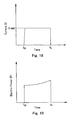
- Fig. 17 to Fig. 20 is a graph of output control performed by the control circuit according to a second embodiment of the invention.
- Fig. 17 is a graph of output voltage with respect to time;
- Fig. 18 is a graph of output current with respect to time;
- Fig. 19 is a graph of output electric power with respect to time;
- Fig. 20 is a graph of electric resistance of the heat-generating body with respect to time.
- the operative instrument 1 of the second embodiment is controlled in such a manner that the current I flowing in the heat-generating body 23 is kept constant (constant current control), and output is stopped when the heat-generating body 23 reaches the upper limit temperature T-limit.
- control circuit 36 is configured to flow a preset current I-set to the heat-generating body 23 by turning the foot switch 5 ON (time to in Fig. 17 to Fig. 20), so that the heat-generating body 23 starts generating heat and hence the temperature increases. As the temperature of the heat-generating body 23 increases, the electric resistance R of the pattern 28 increases as well.
- the control circuit 36 stops the output from the output circuit 31 when the electric resistance R of the pattern 28 reaches the preset threshold R-limit (a value of resistance of the pattern 28 at the upper limit temperature T-limit) (time t1 in Fig. 17 to Fig. 20). Accordingly, the temperature of the heat-generating body 23 does not exceed the preset upper limit temperature T-limit. During output, the voltage V applied to the heat-generating body 23 gradually increases.
- Fig. 23 is a graph of output electric power with respect to time
- Fig. 24 is a graph of electric resistance of the heat-generating body with respect to time.
- the third embodiment is based on constant electric power control. Since other structures are the same as in the first embodiment, description will not be made again and the same structures are represented by the same reference numerals in description.
- the electric power P supplied to the heat-generating body 23 is kept constant (constant electric power control), and output is stopped when the heat-generating body 23 reaches the preset upper limit temperature T-limit as shown in Fig. 21 to Fig. 24.
- a preset electric power P-set is supplied to the heat-generating body 23 by turning the foot switch 5 ON (time to in Fig. 21 to Fig. 24), and the heat-generating body 23 starts generating heat and hence the temperature increases.
- the electric resistance R of the pattern 28 increases with increase in temperature of the heat-generating body 23.
- control circuit 36 stops output from the output circuit 31 when the electric resistance R of the pattern 28 reaches the preset threshold R-limit (value of resistance of the pattern at the upper limit temperature T-limit) (time t1 in Fig. 21 to Fig. 24).
- the temperature of the heat-generating body 23 does not exceed the preset upper limit temperature T-limit.
- the electric power P supplied to the heat-generating body 23 is constant during output. incision operation in a short time. Accordingly, the operative instrument 1 can perform quick incision while keeping a sufficient coagulating capacity.
- the second embodiment can prevent power output in a state in which the forceps 2 are not gripping the anatomy as in the first embodiment, safety during treatment is improved.
- the operative instrument 1 according to the second embodiment prevents rapid changes in temperature of the heat-generating body 23.
- the second embodiment in the same manner as with the first embodiment described above, it is also possible to input the preset current I-set, the changing temperature T-change, and the preset temperature T-set via the panel input/display unit 35, and then perform constant current control followed by constant temperature control.
- the operative instrument 1 of the second embodiment can achieve the same effect as the first embodiment.
- Fig. 21 to Fig. 24 are graphs of output control performed by a control circuit according to a third embodiment of the invention.
- Fig. 21 is a graph showing output voltage with respect to time;
- Fig. 22 is a graph of output current with respect to
- the operative instrument 1 can perform quick incision while keeping a sufficient coagulating capacity.
- V-start (P-set * V-m / I-m) 1/2
- V-m represents voltage to be applied to the heat-generating body 23 for supplying the monitoring current I-m.
- constant electric power control by the control circuit 36 is started by applying the starting voltage value V-start.
- an excessive voltage V is not applied to the heat-generating body 23 when starting the power output.
- the operative instrument 1 according to the third embodiment may be configured in such a manner that the monitoring current I-m is constantly supplied and constant electric power control is started immediately after the foot switch 5 is turned ON.
- the operative instrument 1 according to the third embodiment since output in a state in which the forceps are not gripping the anatomy can be prevented as in the first embodiment, safety during treatment is improved.
- the operative instrument 1 according to the third embodiment prevents rapid changes in temperature of the heat-generating body 23.
- the operative instrument 1 as in the case of the first embodiment described above, it is also possible to input the preset electric power P-set, the changing temperature T-change, and the preset temperature T-set via the panel input/display unit 35, and then perform constant electric power control followed by constant temperature control.
- the operative instrument is controlled in such a manner that output voltage immediately after starting heat generation is gradually increased during constant voltage control of the heat-generating body.
- Fig. 25 to Fig. 27 are graphs in which output voltage and output electric power immediately after starting heat generation are controlled.
- Fig. 25 is a graph of output voltage to the heat-generating body in the constant voltage control;
- Fig. 26 is a graph of a first modification of Fig. 25;
- Fig. 27 is a graph of a second modification of Fig. 25.
- the operative instrument is configured in such a manner that voltage gradually increases for a predetermined time period T1 immediately after starting output and reaches a predetermined voltage V1 after T1 has elapsed in the constant voltage control (T1 is on the order of 1ms to 1s).
- the operative instrument further divides change in voltage immediately after starting output timewise, so that it changes smoothly immediately after starting output and when reaching the predetermined voltage V1.
- the operative instrument may be controlled by changing output electric power immediately after starting output.
- the operative instrument is configured to increase the temperature of the heat-generating body efficiently by performing constant voltage control when outputting electric power, and then to perform control of applying voltage in pulses.
- Fig. 28 to Fig. 35 are graphs of electric power supply control in which constant voltage control is performed when outputting electric power to efficiently increase the temperature of the heat-generating body, by applying voltage in pulses.
- Fig. 28 is a graph of voltage control with respect to time.
- Fig. 29 is a graph of a first modification of Fig. 28;
- Fig. 30 is a graph of a second modification of Fig. 28;
- Fig. 31 is a graph of voltage control with respect to time when a thermal load is high; and
- Fig. 32 is a graph of voltage control with respect to time when the thermal load is low.
- Fig. 33 is a graph of cumulative makeup heat quantity control with respect to time;
- Fig. 34 is a graph of the temperature control of the heat-generating body or the anatomy with respect to time; and
- Fig. 35 is a graph of voltage control with respect to time.
- the operative instrument is driven by constant voltage control for the time period T1 after the power supply unit has started outputting and increase the temperature of the heat-generating body.
- control is switched to pulse control and energy to be supplied to the heat-generating body is reduced by constant voltage control.
- the operative instrument raises the temperature of the anatomy modestly or gradually, and hence carbonization of the anatomy is prevented, so that reliable coagulation is ensured.
- the parameter of output may be electric power control as shown in Fig. 29.
- Switching from constant voltage control to pulse control may be achieved by providing a function for monitoring the temperature of the heat-generating body or the temperature of the anatomy to the power source and switching output control of the power source from constant voltage control to pulse control at a time when the temperature reaches a given threshold A as shown in Fig 30.
- the threshold may be not only the temperature, but also the time period from the moment when output is started, or the value of the cumulative makeup heat quantity from the moment when output is started.
- the operative instrument can achieve a desired temperature rapidly by constant voltage or constant electric power control. After having reached the desired temperature, the operative instrument outputs power by pulse control for preventing excessive heating of the anatomy, and hence reliable coagulation is achieved while minimizing heat supply to the anatomy.
- the operative instrument can achieve reliable coagulation without causing carbonization of the anatomy.
- Duty ratio the ratio between ON-OFF durations of pulse control
- the operative instrument is configured so that the operator can select Duty ratio by setting of the power source depending on the magnitude of the thermal load applied to the heat-generating body.
- the operative instrument is configured in such a manner that the ratio of ON duration of Duty ratio is increased when the thermal load is high as shown in Fig. 31, and the ratio of ON duration is decreased when the thermal load is low as shown in Fig. 32 by the selection of setting of the power source by the operator.
- the operative instrument can select an optimal setting depending on the anatomy or the treatment instrument, and hence reliable coagulation of the anatomy is possible without causing carbonization.
- the operative instrument may be configured in such a manner that a function for monitoring cumulative heat quantity to be outputted to the anatomy (not shown) is provided to the power supply unit.
- thresholds A1, A2 may be provided in temperature of the heat-generating body or the temperature of the anatomy.
- the operative instrument can stop output from the power supply unit automatically, and hence reliable coagulation is achieved without causing carbonization of the anatomy.
- the operative instrument can be configured by combining controls from Fig. 28 to Fig. 34.
- the operative instrument increases the temperature of the heat-generating body by constant voltage control from the moment when output is started to a given timing t1.
- the operative instrument converts control from constant voltage control to pulse control when the given timing t1 has elapsed.
- the timing t1 may be set by providing a threshold to the temperature of the heat-generating body or the anatomy as described in conjunction with Fig. 30, or by providing a threshold to the cumulative makeup heat quantity as described in conjunction with Fig. 33.
- the pulse control is adapted in such a manner that the operator can select Duty ratio as described in conjunction with Fig. 31 and Fig. 32.
- the operative instrument is adapted to continue pulse control after the pulse control is stared until a given timing t2, and then after the timing t2, to switch the constant voltage control again, so that incision of the anatomy is performed in association with increase in temperature of the heat-generating body.
- Setting of the timing t2 may be performed by providing a threshold to the temperature or the makeup heat quantity as in the case of the timing t1, or may be set in advance.
- the parameter of output may be voltage, current, or electric power.
- the operative instrument switches control of constant voltage, pulse, and constant voltage automatically, and can perform treatment to carry out raising the temperature of the heat-generating body, coagulating the anatomy, and incising the anatomy in ordered fashion.
- the operative instrument can achieve reliable coagulation and incision simultaneously while minimizing thermal damage of the anatomy.
Landscapes
- Health & Medical Sciences (AREA)
- Surgery (AREA)
- Engineering & Computer Science (AREA)
- Life Sciences & Earth Sciences (AREA)
- Biomedical Technology (AREA)
- Otolaryngology (AREA)
- Nuclear Medicine, Radiotherapy & Molecular Imaging (AREA)
- Plasma & Fusion (AREA)
- Physics & Mathematics (AREA)
- Heart & Thoracic Surgery (AREA)
- Medical Informatics (AREA)
- Molecular Biology (AREA)
- Animal Behavior & Ethology (AREA)
- General Health & Medical Sciences (AREA)
- Public Health (AREA)
- Veterinary Medicine (AREA)
- Surgical Instruments (AREA)
Applications Claiming Priority (2)
| Application Number | Priority Date | Filing Date | Title |
|---|---|---|---|
| JP2004071405 | 2004-03-12 | ||
| JP2004071405A JP4624697B2 (ja) | 2004-03-12 | 2004-03-12 | 手術用処置具 |
Publications (2)
| Publication Number | Publication Date |
|---|---|
| EP1582165A1 true EP1582165A1 (de) | 2005-10-05 |
| EP1582165B1 EP1582165B1 (de) | 2015-07-08 |
Family
ID=34879870
Family Applications (1)
| Application Number | Title | Priority Date | Filing Date |
|---|---|---|---|
| EP05005029.3A Expired - Fee Related EP1582165B1 (de) | 2004-03-12 | 2005-03-08 | Behandlungsinstrument mit Wärmeerzeuger |
Country Status (3)
| Country | Link |
|---|---|
| US (2) | US20050222560A1 (de) |
| EP (1) | EP1582165B1 (de) |
| JP (1) | JP4624697B2 (de) |
Cited By (6)
| Publication number | Priority date | Publication date | Assignee | Title |
|---|---|---|---|---|
| EP1829493A1 (de) * | 2004-12-24 | 2007-09-05 | Olympus Medical Systems Corp. | Wärmeerzeugendes behandlungsgerät |
| EP2653125A1 (de) * | 2010-12-14 | 2013-10-23 | Olympus Corporation | Therapeutische vorrichtung und steuerungsverfahren dafür |
| CN103932784A (zh) * | 2012-07-31 | 2014-07-23 | 温州智创科技有限公司 | 一种带镊尖清洁功能的电凝镊系统 |
| CN103932783A (zh) * | 2012-07-31 | 2014-07-23 | 温州智创科技有限公司 | 一种新型智能电凝镊系统 |
| CN103997979A (zh) * | 2011-12-12 | 2014-08-20 | 奥林巴斯医疗株式会社 | 处置系统以及处置系统的控制方法 |
| US9155884B2 (en) | 2011-12-12 | 2015-10-13 | Olympus Corporation | Treatment system and actuation method for treatment system |
Families Citing this family (192)
| Publication number | Priority date | Publication date | Assignee | Title |
|---|---|---|---|---|
| US7364577B2 (en) | 2002-02-11 | 2008-04-29 | Sherwood Services Ag | Vessel sealing system |
| US7473253B2 (en) | 2001-04-06 | 2009-01-06 | Covidien Ag | Vessel sealer and divider with non-conductive stop members |
| US7367976B2 (en) | 2003-11-17 | 2008-05-06 | Sherwood Services Ag | Bipolar forceps having monopolar extension |
| US7628791B2 (en) | 2005-08-19 | 2009-12-08 | Covidien Ag | Single action tissue sealer |
| CA2561034C (en) | 2005-09-30 | 2014-12-09 | Sherwood Services Ag | Flexible endoscopic catheter with an end effector for coagulating and transfecting tissue |
| US8298232B2 (en) | 2006-01-24 | 2012-10-30 | Tyco Healthcare Group Lp | Endoscopic vessel sealer and divider for large tissue structures |
| US8882766B2 (en) | 2006-01-24 | 2014-11-11 | Covidien Ag | Method and system for controlling delivery of energy to divide tissue |
| US8475453B2 (en) | 2006-10-06 | 2013-07-02 | Covidien Lp | Endoscopic vessel sealer and divider having a flexible articulating shaft |
| US20090076506A1 (en) * | 2007-09-18 | 2009-03-19 | Surgrx, Inc. | Electrosurgical instrument and method |
| US8623276B2 (en) | 2008-02-15 | 2014-01-07 | Covidien Lp | Method and system for sterilizing an electrosurgical instrument |
| US8357158B2 (en) | 2008-04-22 | 2013-01-22 | Covidien Lp | Jaw closure detection system |
| US8469956B2 (en) | 2008-07-21 | 2013-06-25 | Covidien Lp | Variable resistor jaw |
| US8142473B2 (en) | 2008-10-03 | 2012-03-27 | Tyco Healthcare Group Lp | Method of transferring rotational motion in an articulating surgical instrument |
| US8197479B2 (en) | 2008-12-10 | 2012-06-12 | Tyco Healthcare Group Lp | Vessel sealer and divider |
| US8246618B2 (en) | 2009-07-08 | 2012-08-21 | Tyco Healthcare Group Lp | Electrosurgical jaws with offset knife |
| US8430876B2 (en) | 2009-08-27 | 2013-04-30 | Tyco Healthcare Group Lp | Vessel sealer and divider with knife lockout |
| US9024237B2 (en) | 2009-09-29 | 2015-05-05 | Covidien Lp | Material fusing apparatus, system and method of use |
| US8512371B2 (en) | 2009-10-06 | 2013-08-20 | Covidien Lp | Jaw, blade and gap manufacturing for surgical instruments with small jaws |
| US8480671B2 (en) | 2010-01-22 | 2013-07-09 | Covidien Lp | Compact jaw including split pivot pin |
| US8556929B2 (en) | 2010-01-29 | 2013-10-15 | Covidien Lp | Surgical forceps capable of adjusting seal plate width based on vessel size |
| US8597295B2 (en) | 2010-04-12 | 2013-12-03 | Covidien Lp | Surgical instrument with non-contact electrical coupling |
| US8439913B2 (en) | 2010-04-29 | 2013-05-14 | Covidien Lp | Pressure sensing sealing plate |
| US8469991B2 (en) | 2010-06-02 | 2013-06-25 | Covidien Lp | Apparatus for performing an electrosurgical procedure |
| US8409247B2 (en) | 2010-06-02 | 2013-04-02 | Covidien Lp | Apparatus for performing an electrosurgical procedure |
| US8430877B2 (en) | 2010-06-02 | 2013-04-30 | Covidien Lp | Apparatus for performing an electrosurgical procedure |
| US8491624B2 (en) | 2010-06-02 | 2013-07-23 | Covidien Lp | Apparatus for performing an electrosurgical procedure |
| US8409246B2 (en) | 2010-06-02 | 2013-04-02 | Covidien Lp | Apparatus for performing an electrosurgical procedure |
| US8298233B2 (en) | 2010-08-20 | 2012-10-30 | Tyco Healthcare Group Lp | Surgical instrument configured for use with interchangeable hand grips |
| US8814864B2 (en) | 2010-08-23 | 2014-08-26 | Covidien Lp | Method of manufacturing tissue sealing electrodes |
| US9113940B2 (en) | 2011-01-14 | 2015-08-25 | Covidien Lp | Trigger lockout and kickback mechanism for surgical instruments |
| US8900232B2 (en) | 2011-05-06 | 2014-12-02 | Covidien Lp | Bifurcated shaft for surgical instrument |
| US8685009B2 (en) | 2011-05-16 | 2014-04-01 | Covidien Lp | Thread-like knife for tissue cutting |
| US9844384B2 (en) | 2011-07-11 | 2017-12-19 | Covidien Lp | Stand alone energy-based tissue clips |
| JP5820649B2 (ja) | 2011-07-25 | 2015-11-24 | オリンパス株式会社 | 治療用処置装置 |
| JP5767053B2 (ja) * | 2011-08-05 | 2015-08-19 | オリンパス株式会社 | 治療用処置装置 |
| US8968306B2 (en) | 2011-08-09 | 2015-03-03 | Covidien Lp | Surgical forceps |
| US9060780B2 (en) | 2011-09-29 | 2015-06-23 | Covidien Lp | Methods of manufacturing shafts for surgical instruments |
| CN102429701A (zh) * | 2011-11-01 | 2012-05-02 | 福州施可瑞光电科技有限公司 | 超声碎石方法及超声碎石钳 |
| US8968309B2 (en) | 2011-11-10 | 2015-03-03 | Covidien Lp | Surgical forceps |
| EP2745793B1 (de) * | 2011-12-12 | 2016-02-24 | Olympus Corporation | Behandlungssystem |
| US8864753B2 (en) | 2011-12-13 | 2014-10-21 | Covidien Lp | Surgical Forceps Connected to Treatment Light Source |
| USD680220S1 (en) | 2012-01-12 | 2013-04-16 | Coviden IP | Slider handle for laparoscopic device |
| US9113897B2 (en) | 2012-01-23 | 2015-08-25 | Covidien Lp | Partitioned surgical instrument |
| US8747434B2 (en) | 2012-02-20 | 2014-06-10 | Covidien Lp | Knife deployment mechanisms for surgical forceps |
| US9011435B2 (en) | 2012-02-24 | 2015-04-21 | Covidien Lp | Method for manufacturing vessel sealing instrument with reduced thermal spread |
| US8887373B2 (en) | 2012-02-24 | 2014-11-18 | Covidien Lp | Vessel sealing instrument with reduced thermal spread and method of manufacture therefor |
| US8920461B2 (en) | 2012-05-01 | 2014-12-30 | Covidien Lp | Surgical forceps with bifurcated flanged jaw components |
| US8968311B2 (en) | 2012-05-01 | 2015-03-03 | Covidien Lp | Surgical instrument with stamped double-flag jaws and actuation mechanism |
| US9034009B2 (en) | 2012-05-01 | 2015-05-19 | Covidien Lp | Surgical forceps |
| US9820765B2 (en) | 2012-05-01 | 2017-11-21 | Covidien Lp | Surgical instrument with stamped double-flange jaws |
| US9668807B2 (en) | 2012-05-01 | 2017-06-06 | Covidien Lp | Simplified spring load mechanism for delivering shaft force of a surgical instrument |
| US9375258B2 (en) | 2012-05-08 | 2016-06-28 | Covidien Lp | Surgical forceps |
| US9039731B2 (en) | 2012-05-08 | 2015-05-26 | Covidien Lp | Surgical forceps including blade safety mechanism |
| US9113901B2 (en) | 2012-05-14 | 2015-08-25 | Covidien Lp | Modular surgical instrument with contained electrical or mechanical systems |
| US9192432B2 (en) | 2012-05-29 | 2015-11-24 | Covidien Lp | Lever latch assemblies for surgical improvements |
| US8679140B2 (en) | 2012-05-30 | 2014-03-25 | Covidien Lp | Surgical clamping device with ratcheting grip lock |
| US8968313B2 (en) | 2012-06-12 | 2015-03-03 | Covidien Lp | Electrosurgical instrument with a knife blade stop |
| US9510891B2 (en) | 2012-06-26 | 2016-12-06 | Covidien Lp | Surgical instruments with structures to provide access for cleaning |
| US9011436B2 (en) | 2012-06-26 | 2015-04-21 | Covidien Lp | Double-length jaw system for electrosurgical instrument |
| US9770255B2 (en) | 2012-06-26 | 2017-09-26 | Covidien Lp | One-piece handle assembly |
| US9039691B2 (en) | 2012-06-29 | 2015-05-26 | Covidien Lp | Surgical forceps |
| US9072524B2 (en) | 2012-06-29 | 2015-07-07 | Covidien Lp | Surgical forceps |
| US10368945B2 (en) | 2012-07-17 | 2019-08-06 | Covidien Lp | Surgical instrument for energy-based tissue treatment |
| US9833285B2 (en) | 2012-07-17 | 2017-12-05 | Covidien Lp | Optical sealing device with cutting ability |
| US8939975B2 (en) | 2012-07-17 | 2015-01-27 | Covidien Lp | Gap control via overmold teeth and hard stops |
| US9301798B2 (en) | 2012-07-19 | 2016-04-05 | Covidien Lp | Surgical forceps including reposable end effector assemblies |
| US9192421B2 (en) | 2012-07-24 | 2015-11-24 | Covidien Lp | Blade lockout mechanism for surgical forceps |
| US9636168B2 (en) | 2012-08-09 | 2017-05-02 | Covidien Lp | Electrosurgical instrument including nested knife assembly |
| US9433461B2 (en) | 2012-09-07 | 2016-09-06 | Covidien Lp | Instruments, systems, and methods for sealing tissue structures |
| US9439711B2 (en) | 2012-10-02 | 2016-09-13 | Covidien Lp | Medical devices for thermally treating tissue |
| US9687290B2 (en) | 2012-10-02 | 2017-06-27 | Covidien Lp | Energy-based medical devices |
| US9549749B2 (en) | 2012-10-08 | 2017-01-24 | Covidien Lp | Surgical forceps |
| US9526564B2 (en) | 2012-10-08 | 2016-12-27 | Covidien Lp | Electric stapler device |
| US9681908B2 (en) | 2012-10-08 | 2017-06-20 | Covidien Lp | Jaw assemblies for electrosurgical instruments and methods of manufacturing jaw assemblies |
| US9375259B2 (en) | 2012-10-24 | 2016-06-28 | Covidien Lp | Electrosurgical instrument including an adhesive applicator assembly |
| US9572529B2 (en) | 2012-10-31 | 2017-02-21 | Covidien Lp | Surgical devices and methods utilizing optical coherence tomography (OCT) to monitor and control tissue sealing |
| US10206583B2 (en) | 2012-10-31 | 2019-02-19 | Covidien Lp | Surgical devices and methods utilizing optical coherence tomography (OCT) to monitor and control tissue sealing |
| US10772674B2 (en) | 2012-11-15 | 2020-09-15 | Covidien Lp | Deployment mechanisms for surgical instruments |
| US9375205B2 (en) | 2012-11-15 | 2016-06-28 | Covidien Lp | Deployment mechanisms for surgical instruments |
| US9498281B2 (en) | 2012-11-27 | 2016-11-22 | Covidien Lp | Surgical apparatus |
| JP5988868B2 (ja) * | 2012-12-27 | 2016-09-07 | オリンパス株式会社 | 治療用処置装置 |
| US9375256B2 (en) | 2013-02-05 | 2016-06-28 | Covidien Lp | Electrosurgical forceps |
| US10265119B2 (en) | 2013-02-15 | 2019-04-23 | Covidien Lp | Electrosurgical forceps |
| US9713491B2 (en) | 2013-02-19 | 2017-07-25 | Covidien Lp | Method for manufacturing an electrode assembly configured for use with an electrosurigcal instrument |
| US9375262B2 (en) | 2013-02-27 | 2016-06-28 | Covidien Lp | Limited use medical devices |
| US9456863B2 (en) | 2013-03-11 | 2016-10-04 | Covidien Lp | Surgical instrument with switch activation control |
| US10070916B2 (en) | 2013-03-11 | 2018-09-11 | Covidien Lp | Surgical instrument with system and method for springing open jaw members |
| US9655673B2 (en) | 2013-03-11 | 2017-05-23 | Covidien Lp | Surgical instrument |
| US9877775B2 (en) | 2013-03-12 | 2018-01-30 | Covidien Lp | Electrosurgical instrument with a knife blade stop |
| US9468453B2 (en) | 2013-05-03 | 2016-10-18 | Covidien Lp | Endoscopic surgical forceps |
| USD728786S1 (en) | 2013-05-03 | 2015-05-05 | Covidien Lp | Vessel sealer with mechanical cutter and pistol-grip-style trigger |
| US9622810B2 (en) | 2013-05-10 | 2017-04-18 | Covidien Lp | Surgical forceps |
| EP3003177B1 (de) | 2013-05-31 | 2021-03-10 | Covidien LP | Chirurgische vorrichtung mit einer endeffektorbaugruppe zur gewebeüberwachung bei chirurgischen eingriffen |
| US9649151B2 (en) | 2013-05-31 | 2017-05-16 | Covidien Lp | End effector assemblies and methods of manufacturing end effector assemblies for treating and/or cutting tissue |
| US9554845B2 (en) | 2013-07-18 | 2017-01-31 | Covidien Lp | Surgical forceps for treating and cutting tissue |
| CN105451677B (zh) | 2013-08-02 | 2018-02-13 | 奥林巴斯株式会社 | 生物体组织接合系统 |
| EP3030179B1 (de) | 2013-08-07 | 2019-05-08 | Covidien LP | Bipolares chirurgisches instrument |
| USD744644S1 (en) | 2013-08-07 | 2015-12-01 | Covidien Lp | Disposable housing for open vessel sealer with mechanical cutter |
| USD726910S1 (en) | 2013-08-07 | 2015-04-14 | Covidien Lp | Reusable forceps for open vessel sealer with mechanical cutter |
| USD736920S1 (en) | 2013-08-07 | 2015-08-18 | Covidien Lp | Open vessel sealer with mechanical cutter |
| US10405874B2 (en) | 2013-08-13 | 2019-09-10 | Covidien Lp | Surgical instrument |
| US9439717B2 (en) | 2013-08-13 | 2016-09-13 | Covidien Lp | Surgical forceps including thermal spread control |
| US9943357B2 (en) | 2013-09-16 | 2018-04-17 | Covidien Lp | Split electrode for use in a bipolar electrosurgical instrument |
| US9445865B2 (en) | 2013-09-16 | 2016-09-20 | Covidien Lp | Electrosurgical instrument with end-effector assembly including electrically-conductive, tissue-engaging surfaces and switchable bipolar electrodes |
| US9717548B2 (en) | 2013-09-24 | 2017-08-01 | Covidien Lp | Electrode for use in a bipolar electrosurgical instrument |
| US10231772B2 (en) | 2013-09-25 | 2019-03-19 | Covidien Lp | Wire retention unit for a surgical instrument |
| US10610289B2 (en) | 2013-09-25 | 2020-04-07 | Covidien Lp | Devices, systems, and methods for grasping, treating, and dividing tissue |
| US9642671B2 (en) | 2013-09-30 | 2017-05-09 | Covidien Lp | Limited-use medical device |
| US9974601B2 (en) | 2013-11-19 | 2018-05-22 | Covidien Lp | Vessel sealing instrument with suction system |
| US10231776B2 (en) | 2014-01-29 | 2019-03-19 | Covidien Lp | Tissue sealing instrument with tissue-dissecting electrode |
| US11090109B2 (en) | 2014-02-11 | 2021-08-17 | Covidien Lp | Temperature-sensing electrically-conductive tissue-contacting plate configured for use in an electrosurgical jaw member, electrosurgical system including same, and methods of controlling vessel sealing using same |
| US10130413B2 (en) | 2014-02-11 | 2018-11-20 | Covidien Lp | Temperature-sensing electrically-conductive tissue-contacting plate and methods of manufacturing same |
| US10342601B2 (en) | 2014-04-02 | 2019-07-09 | Covidien Lp | Electrosurgical devices including transverse electrode configurations |
| US10278768B2 (en) | 2014-04-02 | 2019-05-07 | Covidien Lp | Electrosurgical devices including transverse electrode configurations |
| US9687295B2 (en) | 2014-04-17 | 2017-06-27 | Covidien Lp | Methods of manufacturing a pair of jaw members of an end-effector assembly for a surgical instrument |
| US20150324317A1 (en) | 2014-05-07 | 2015-11-12 | Covidien Lp | Authentication and information system for reusable surgical instruments |
| US10660694B2 (en) | 2014-08-27 | 2020-05-26 | Covidien Lp | Vessel sealing instrument and switch assemblies thereof |
| US10820939B2 (en) | 2014-09-15 | 2020-11-03 | Covidien Lp | Vessel-sealing device including force-balance interface and electrosurgical system including same |
| US10080605B2 (en) | 2014-09-17 | 2018-09-25 | Covidien Lp | Deployment mechanisms for surgical instruments |
| US9987076B2 (en) | 2014-09-17 | 2018-06-05 | Covidien Lp | Multi-function surgical instruments |
| US10039592B2 (en) | 2014-09-17 | 2018-08-07 | Covidien Lp | Deployment mechanisms for surgical instruments |
| US9918785B2 (en) | 2014-09-17 | 2018-03-20 | Covidien Lp | Deployment mechanisms for surgical instruments |
| US10080606B2 (en) | 2014-09-17 | 2018-09-25 | Covidien Lp | Method of forming a member of an end effector |
| US9877777B2 (en) | 2014-09-17 | 2018-01-30 | Covidien Lp | Surgical instrument having a bipolar end effector assembly and a deployable monopolar assembly |
| US10258360B2 (en) | 2014-09-25 | 2019-04-16 | Covidien Lp | Surgical instruments |
| JP5959789B1 (ja) | 2014-10-15 | 2016-08-02 | オリンパス株式会社 | エネルギ処置具のための制御装置、及びエネルギ処置システム |
| US10463422B2 (en) | 2014-12-18 | 2019-11-05 | Covidien Lp | Surgical instrument with stopper assembly |
| US10172612B2 (en) | 2015-01-21 | 2019-01-08 | Covidien Lp | Surgical instruments with force applier and methods of use |
| CN104605916A (zh) * | 2015-01-27 | 2015-05-13 | 谈帅 | 一种肝胆手术止血钳 |
| CN107405167B (zh) * | 2015-02-27 | 2020-06-16 | 奥林巴斯株式会社 | 医疗用处置装置和医疗用处置装置的工作方法 |
| US10653476B2 (en) | 2015-03-12 | 2020-05-19 | Covidien Lp | Mapping vessels for resecting body tissue |
| US10206736B2 (en) | 2015-03-13 | 2019-02-19 | Covidien Lp | Surgical forceps with scalpel functionality |
| CN107427323B (zh) | 2015-03-31 | 2021-02-02 | 圣犹达医疗用品心脏病学部门有限公司 | 高热敏性消融导管和导管尖端 |
| US10758257B2 (en) | 2015-04-24 | 2020-09-01 | Covidien Lp | Vessel sealing device with fine dissection function |
| WO2016169038A1 (en) | 2015-04-24 | 2016-10-27 | Covidien Lp | Multifunctional vessel sealing and divider device |
| US10441340B2 (en) | 2015-05-27 | 2019-10-15 | Covidien Lp | Surgical forceps |
| US9956022B2 (en) | 2015-05-27 | 2018-05-01 | Covidien Lp | Surgical forceps and methods of manufacturing the same |
| US9974602B2 (en) | 2015-05-27 | 2018-05-22 | Covidien Lp | Surgical instruments and devices and methods facilitating the manufacture of the same |
| US9848935B2 (en) | 2015-05-27 | 2017-12-26 | Covidien Lp | Surgical instruments including components and features facilitating the assembly and manufacturing thereof |
| US10226269B2 (en) | 2015-05-27 | 2019-03-12 | Covidien Lp | Surgical forceps |
| US10722293B2 (en) | 2015-05-29 | 2020-07-28 | Covidien Lp | Surgical device with an end effector assembly and system for monitoring of tissue before and after a surgical procedure |
| US10213221B2 (en) | 2015-10-28 | 2019-02-26 | Covidien Lp | Surgical instruments including cam surfaces |
| US10154877B2 (en) | 2015-11-04 | 2018-12-18 | Covidien Lp | Endoscopic surgical instrument |
| US10172672B2 (en) | 2016-01-11 | 2019-01-08 | Covidien Lp | Jaw force control for electrosurgical forceps |
| US10695123B2 (en) | 2016-01-29 | 2020-06-30 | Covidien Lp | Surgical instrument with sensor |
| US10864003B2 (en) | 2016-02-05 | 2020-12-15 | Covidien Lp | Articulation assemblies for use with endoscopic surgical instruments |
| US10537381B2 (en) | 2016-02-26 | 2020-01-21 | Covidien Lp | Surgical instrument having a bipolar end effector assembly and a deployable monopolar assembly |
| USD828554S1 (en) | 2016-03-09 | 2018-09-11 | Covidien Lp | Contoured blade trigger for an electrosurgical instrument |
| USD819815S1 (en) | 2016-03-09 | 2018-06-05 | Covidien Lp | L-shaped blade trigger for an electrosurgical instrument |
| US10517665B2 (en) | 2016-07-14 | 2019-12-31 | Covidien Lp | Devices and methods for tissue sealing and mechanical clipping |
| CN109640853B (zh) | 2016-08-04 | 2021-10-22 | 奥林巴斯株式会社 | 控制装置 |
| US10631887B2 (en) | 2016-08-15 | 2020-04-28 | Covidien Lp | Electrosurgical forceps for video assisted thoracoscopic surgery and other surgical procedures |
| US10441305B2 (en) | 2016-08-18 | 2019-10-15 | Covidien Lp | Surgical forceps |
| US10772642B2 (en) | 2016-08-18 | 2020-09-15 | Covidien Lp | Surgical forceps |
| EP3522809B1 (de) | 2016-10-04 | 2021-11-24 | St. Jude Medical, Cardiology Division, Inc. | Ablationskatheterspitze |
| WO2018078797A1 (ja) * | 2016-10-28 | 2018-05-03 | オリンパス株式会社 | 医療用処置装置、及び医療用処置装置の作動方法 |
| US11207091B2 (en) | 2016-11-08 | 2021-12-28 | Covidien Lp | Surgical instrument for grasping, treating, and/or dividing tissue |
| US10813695B2 (en) | 2017-01-27 | 2020-10-27 | Covidien Lp | Reflectors for optical-based vessel sealing |
| US11229480B2 (en) | 2017-02-02 | 2022-01-25 | Covidien Lp | Latching mechanism for in-line activated electrosurgical device |
| US10881445B2 (en) | 2017-02-09 | 2021-01-05 | Covidien Lp | Adapters, systems incorporating the same, and methods for providing an electrosurgical forceps with clip-applying functionality |
| EP3595561B1 (de) | 2017-03-13 | 2021-12-01 | Covidien LP | Elektrochirurgisches instrument mit auslösungsgesteuerter schneidfunktion |
| US11172980B2 (en) | 2017-05-12 | 2021-11-16 | Covidien Lp | Electrosurgical forceps for grasping, treating, and/or dividing tissue |
| US10973567B2 (en) | 2017-05-12 | 2021-04-13 | Covidien Lp | Electrosurgical forceps for grasping, treating, and/or dividing tissue |
| US10512501B2 (en) | 2017-06-08 | 2019-12-24 | Covidien Lp | Electrosurgical apparatus |
| US10653475B2 (en) | 2017-06-08 | 2020-05-19 | Covidien Lp | Knife lockout for electrosurgical forceps |
| USD854149S1 (en) | 2017-06-08 | 2019-07-16 | Covidien Lp | End effector for open vessel sealer |
| USD854684S1 (en) | 2017-06-08 | 2019-07-23 | Covidien Lp | Open vessel sealer with mechanical cutter |
| USD859658S1 (en) | 2017-06-16 | 2019-09-10 | Covidien Lp | Vessel sealer for tonsillectomy |
| US10932808B2 (en) | 2017-08-29 | 2021-03-02 | Ethicon Llc | Methods, systems, and devices for controlling electrosurgical tools |
| US10888370B2 (en) * | 2017-08-29 | 2021-01-12 | Ethicon Llc | Methods, systems, and devices for controlling electrosurgical tools |
| US11154348B2 (en) | 2017-08-29 | 2021-10-26 | Covidien Lp | Surgical instruments and methods of assembling surgical instruments |
| US10905493B2 (en) | 2017-08-29 | 2021-02-02 | Ethicon Llc | Methods, systems, and devices for controlling electrosurgical tools |
| US11123132B2 (en) | 2018-04-09 | 2021-09-21 | Covidien Lp | Multi-function surgical instruments and assemblies therefor |
| US10828756B2 (en) | 2018-04-24 | 2020-11-10 | Covidien Lp | Disassembly methods facilitating reprocessing of multi-function surgical instruments |
| US11033289B2 (en) | 2018-05-02 | 2021-06-15 | Covidien Lp | Jaw guard for surgical forceps |
| US11109930B2 (en) | 2018-06-08 | 2021-09-07 | Covidien Lp | Enhanced haptic feedback system |
| US11896291B2 (en) | 2018-07-02 | 2024-02-13 | Covidien Lp | Electrically-insulative shafts, methods of manufacturing electrically-insulative shafts, and energy-based surgical instruments incorporating electrically-insulative shafts |
| US11612403B2 (en) | 2018-10-03 | 2023-03-28 | Covidien Lp | Multi-function surgical transection instrument |
| US11376062B2 (en) | 2018-10-12 | 2022-07-05 | Covidien Lp | Electrosurgical forceps |
| US11471211B2 (en) | 2018-10-12 | 2022-10-18 | Covidien Lp | Electrosurgical forceps |
| US10881452B2 (en) | 2018-10-16 | 2021-01-05 | Covidien Lp | Method of assembling an end effector for a surgical instrument |
| US11350982B2 (en) | 2018-12-05 | 2022-06-07 | Covidien Lp | Electrosurgical forceps |
| US11246648B2 (en) | 2018-12-10 | 2022-02-15 | Covidien Lp | Surgical forceps with bilateral and unilateral jaw members |
| US11147613B2 (en) | 2019-03-15 | 2021-10-19 | Covidien Lp | Surgical instrument with increased lever stroke |
| US11523861B2 (en) | 2019-03-22 | 2022-12-13 | Covidien Lp | Methods for manufacturing a jaw assembly for an electrosurgical forceps |
| US11576696B2 (en) | 2019-03-29 | 2023-02-14 | Covidien Lp | Engagement features and methods for attaching a drive rod to a knife blade in an articulating surgical instrument |
| US11490916B2 (en) | 2019-03-29 | 2022-11-08 | Covidien Lp | Engagement features and methods for attaching a drive rod to a knife blade in an articulating surgical instrument |
| US11490917B2 (en) | 2019-03-29 | 2022-11-08 | Covidien Lp | Drive rod and knife blade for an articulating surgical instrument |
| US11607267B2 (en) | 2019-06-10 | 2023-03-21 | Covidien Lp | Electrosurgical forceps |
| US11376030B2 (en) | 2020-02-10 | 2022-07-05 | Covidien Lp | Devices and methods facilitating the manufacture of surgical instruments |
| US11622804B2 (en) | 2020-03-16 | 2023-04-11 | Covidien Lp | Forceps with linear trigger mechanism |
| US11844562B2 (en) | 2020-03-23 | 2023-12-19 | Covidien Lp | Electrosurgical forceps for grasping, treating, and/or dividing tissue |
Citations (6)
| Publication number | Priority date | Publication date | Assignee | Title |
|---|---|---|---|---|
| US4031898A (en) * | 1974-12-03 | 1977-06-28 | Siegfried Hiltebrandt | Surgical instrument for coagulation purposes |
| US4196734A (en) * | 1978-02-16 | 1980-04-08 | Valleylab, Inc. | Combined electrosurgery/cautery system and method |
| WO2001012090A1 (en) * | 1999-08-13 | 2001-02-22 | The Trustees Of Columbia University In The City Of New York | Electrothermal device for coagulating, sealing and cutting tissue during surgery |
| WO2002032333A1 (en) * | 2000-10-17 | 2002-04-25 | Broncus Technologies, Inc. | Control system and process for application of energy to airway walls and other mediums |
| US20030171747A1 (en) * | 1999-01-25 | 2003-09-11 | Olympus Optical Co., Ltd. | Medical treatment instrument |
| WO2004002346A1 (en) * | 2002-06-28 | 2004-01-08 | Oratec Interventions, Inc. | Method and apparatus for controlling a temperature-controlled probe |
Family Cites Families (36)
| Publication number | Priority date | Publication date | Assignee | Title |
|---|---|---|---|---|
| GB1521460A (en) * | 1974-08-30 | 1978-08-16 | Raychem Corp | Self-limiting electrically resistive article and process for its manufacture |
| GB8418796D0 (en) * | 1984-07-24 | 1984-08-30 | Ellis C R | Instruments for treating nails |
| DE3546697C2 (de) * | 1984-09-13 | 1992-02-06 | Olympus Optical Co., Ltd., Tokio/Tokyo, Jp | |
| JPS61288852A (ja) * | 1985-06-15 | 1986-12-19 | オリンパス光学工業株式会社 | 焼灼止血装置 |
| JP2673968B2 (ja) * | 1990-07-10 | 1997-11-05 | キヤノン株式会社 | 温度制御装置 |
| US5277201A (en) * | 1992-05-01 | 1994-01-11 | Vesta Medical, Inc. | Endometrial ablation apparatus and method |
| US5445635A (en) * | 1992-05-01 | 1995-08-29 | Hemostatic Surgery Corporation | Regulated-current power supply and methods for resistively-heated surgical instruments |
| JPH0663056A (ja) * | 1992-08-14 | 1994-03-08 | Central Kogyo Kk | 医療用高周波焼灼装置 |
| US6409722B1 (en) * | 1998-07-07 | 2002-06-25 | Medtronic, Inc. | Apparatus and method for creating, maintaining, and controlling a virtual electrode used for the ablation of tissue |
| US5707369A (en) * | 1995-04-24 | 1998-01-13 | Ethicon Endo-Surgery, Inc. | Temperature feedback monitor for hemostatic surgical instrument |
| US6461357B1 (en) * | 1997-02-12 | 2002-10-08 | Oratec Interventions, Inc. | Electrode for electrosurgical ablation of tissue |
| US6033399A (en) * | 1997-04-09 | 2000-03-07 | Valleylab, Inc. | Electrosurgical generator with adaptive power control |
| JPH10286260A (ja) * | 1997-04-15 | 1998-10-27 | Olympus Optical Co Ltd | 焼灼止血装置 |
| JP3911334B2 (ja) * | 1998-01-08 | 2007-05-09 | オリンパス株式会社 | 焼灼止血装置 |
| US6322584B2 (en) * | 1998-07-31 | 2001-11-27 | Surx, Inc. | Temperature sensing devices and methods to shrink tissues |
| US6436096B1 (en) * | 1998-11-27 | 2002-08-20 | Olympus Optical Co., Ltd. | Electrosurgical apparatus with stable coagulation |
| JP2001340349A (ja) * | 2000-06-01 | 2001-12-11 | Olympus Optical Co Ltd | 手術器械 |
| US6692489B1 (en) * | 1999-07-21 | 2004-02-17 | Team Medical, Llc | Electrosurgical mode conversion system |
| JP2001190561A (ja) * | 2000-01-12 | 2001-07-17 | Olympus Optical Co Ltd | 凝固処置具 |
| JP2001269352A (ja) * | 2000-03-23 | 2001-10-02 | Olympus Optical Co Ltd | 発熱処置具用電源 |
| US6350969B1 (en) * | 2000-11-10 | 2002-02-26 | Jona Group, Ltd. | Self-regulating heater |
| US6740085B2 (en) * | 2000-11-16 | 2004-05-25 | Olympus Corporation | Heating treatment system |
| WO2002069821A1 (en) * | 2001-03-06 | 2002-09-12 | Thermemed Corp. | Vaporous delivery of thermal energy to tissue sites |
| US6648883B2 (en) * | 2001-04-26 | 2003-11-18 | Medtronic, Inc. | Ablation system and method of use |
| US6923804B2 (en) * | 2001-07-12 | 2005-08-02 | Neothermia Corporation | Electrosurgical generator |
| US6926716B2 (en) * | 2001-11-09 | 2005-08-09 | Surgrx Inc. | Electrosurgical instrument |
| US6695837B2 (en) * | 2002-03-13 | 2004-02-24 | Starion Instruments Corporation | Power supply for identification and control of electrical surgical tools |
| US6929643B2 (en) * | 2002-04-15 | 2005-08-16 | Olympus Corporation | Resectoscope apparatus and electric operation apparatus |
| US7458969B2 (en) * | 2002-05-06 | 2008-12-02 | Olympus Corporation | Therapeutic device for tissue from living body |
| US7108694B2 (en) * | 2002-11-08 | 2006-09-19 | Olympus Corporation | Heat-emitting treatment device |
| US7169146B2 (en) * | 2003-02-14 | 2007-01-30 | Surgrx, Inc. | Electrosurgical probe and method of use |
| US7326202B2 (en) * | 2003-03-07 | 2008-02-05 | Starion Instruments Corporation | Tubular resistance heater with electrically insulating high thermal conductivity core for use in a tissue welding device |
| US7011656B2 (en) * | 2003-11-14 | 2006-03-14 | Starion Instruments Corporation | Thermal cautery devices with improved heating profiles |
| US7169145B2 (en) * | 2003-11-21 | 2007-01-30 | Megadyne Medical Products, Inc. | Tuned return electrode with matching inductor |
| US7329255B2 (en) * | 2003-12-23 | 2008-02-12 | Starion Instruments Corporation | System for regulating heating in a tissue sealing and cutting device |
| US7094231B1 (en) * | 2004-01-22 | 2006-08-22 | Ellman Alan G | Dual-mode electrosurgical instrument |
-
2004
- 2004-03-12 JP JP2004071405A patent/JP4624697B2/ja not_active Expired - Fee Related
-
2005
- 2005-03-08 EP EP05005029.3A patent/EP1582165B1/de not_active Expired - Fee Related
- 2005-03-11 US US11/077,861 patent/US20050222560A1/en not_active Abandoned
-
2010
- 2010-08-09 US US12/852,766 patent/US20100305558A1/en not_active Abandoned
Patent Citations (6)
| Publication number | Priority date | Publication date | Assignee | Title |
|---|---|---|---|---|
| US4031898A (en) * | 1974-12-03 | 1977-06-28 | Siegfried Hiltebrandt | Surgical instrument for coagulation purposes |
| US4196734A (en) * | 1978-02-16 | 1980-04-08 | Valleylab, Inc. | Combined electrosurgery/cautery system and method |
| US20030171747A1 (en) * | 1999-01-25 | 2003-09-11 | Olympus Optical Co., Ltd. | Medical treatment instrument |
| WO2001012090A1 (en) * | 1999-08-13 | 2001-02-22 | The Trustees Of Columbia University In The City Of New York | Electrothermal device for coagulating, sealing and cutting tissue during surgery |
| WO2002032333A1 (en) * | 2000-10-17 | 2002-04-25 | Broncus Technologies, Inc. | Control system and process for application of energy to airway walls and other mediums |
| WO2004002346A1 (en) * | 2002-06-28 | 2004-01-08 | Oratec Interventions, Inc. | Method and apparatus for controlling a temperature-controlled probe |
Cited By (14)
| Publication number | Priority date | Publication date | Assignee | Title |
|---|---|---|---|---|
| EP1829493A4 (de) * | 2004-12-24 | 2008-04-09 | Olympus Medical Systems Corp | Wärmeerzeugendes behandlungsgerät |
| EP1829493A1 (de) * | 2004-12-24 | 2007-09-05 | Olympus Medical Systems Corp. | Wärmeerzeugendes behandlungsgerät |
| EP2653125A1 (de) * | 2010-12-14 | 2013-10-23 | Olympus Corporation | Therapeutische vorrichtung und steuerungsverfahren dafür |
| US9833278B2 (en) | 2010-12-14 | 2017-12-05 | Olympus Corporation | Medical treatment apparatus and method of controlling the same |
| EP2653125A4 (de) * | 2010-12-14 | 2015-01-14 | Olympus Corp | Therapeutische vorrichtung und steuerungsverfahren dafür |
| CN103997979B (zh) * | 2011-12-12 | 2016-07-06 | 奥林巴斯株式会社 | 处置系统以及处置系统的动作方法 |
| CN103997979A (zh) * | 2011-12-12 | 2014-08-20 | 奥林巴斯医疗株式会社 | 处置系统以及处置系统的控制方法 |
| EP2769694A4 (de) * | 2011-12-12 | 2015-06-24 | Olympus Medical Systems Corp | Behandlungssystem und verfahren zur steuerung eines behandlungssystems |
| US9155884B2 (en) | 2011-12-12 | 2015-10-13 | Olympus Corporation | Treatment system and actuation method for treatment system |
| US9414882B2 (en) | 2011-12-12 | 2016-08-16 | Olympus Corporation | Treatment system and actuation method for treatment system |
| CN103932784A (zh) * | 2012-07-31 | 2014-07-23 | 温州智创科技有限公司 | 一种带镊尖清洁功能的电凝镊系统 |
| CN103932784B (zh) * | 2012-07-31 | 2016-03-23 | 温州智创科技有限公司 | 一种带镊尖清洁功能的电凝镊系统 |
| CN103932783B (zh) * | 2012-07-31 | 2016-08-17 | 温州智创科技有限公司 | 一种智能电凝镊系统 |
| CN103932783A (zh) * | 2012-07-31 | 2014-07-23 | 温州智创科技有限公司 | 一种新型智能电凝镊系统 |
Also Published As
| Publication number | Publication date |
|---|---|
| EP1582165B1 (de) | 2015-07-08 |
| US20100305558A1 (en) | 2010-12-02 |
| US20050222560A1 (en) | 2005-10-06 |
| JP2005253789A (ja) | 2005-09-22 |
| JP4624697B2 (ja) | 2011-02-02 |
Similar Documents
| Publication | Publication Date | Title |
|---|---|---|
| EP1582165B1 (de) | Behandlungsinstrument mit Wärmeerzeuger | |
| US9937001B2 (en) | Therapeutic treatment apparatus | |
| JP5544046B2 (ja) | 処置システムおよび処置システムの作動方法 | |
| WO2018167878A1 (ja) | エネルギー源装置 | |
| US9808305B2 (en) | Energy treatment apparatus | |
| JP4734058B2 (ja) | 医療用処置装置 | |
| EP3108838B1 (de) | Haltende behandlungsvorrichtung | |
| JP2002325772A (ja) | 電気手術装置 | |
| WO2017018205A1 (ja) | エネルギー処置システム、エネルギー制御装置及びエネルギー処置具 | |
| JP5425344B2 (ja) | 処置システム及び処置システムの作動方法 | |
| JP5814685B2 (ja) | 治療用処置装置 | |
| US9504515B2 (en) | Treatment device | |
| WO2013015251A1 (ja) | 治療用処置装置 | |
| EP3199117A1 (de) | Thermotherapeutische vorrichtung und steuerungsverfahren dafür | |
| JPWO2013088891A1 (ja) | 処置システム及び処置システムの作動方法 | |
| WO2006068243A1 (ja) | 発熱処置装置 | |
| WO2013021806A1 (ja) | 治療用処置装置 | |
| US10314636B2 (en) | Treatment apparatus and method for controlling the same | |
| US10034703B2 (en) | Control device for energy treatment tool, and energy treatment system | |
| CN113840575B (zh) | 医疗装置和控制方法 | |
| WO2016093086A1 (ja) | 処置装置 | |
| JP2012249807A (ja) | 治療用処置装置及びその制御方法 | |
| JP2005160733A (ja) | 手術用処置具 | |
| WO2019224924A1 (ja) | 処置システム、制御方法、及び制御プログラム | |
| JP2005230189A (ja) | 手術用処置装置 |
Legal Events
| Date | Code | Title | Description |
|---|---|---|---|
| PUAI | Public reference made under article 153(3) epc to a published international application that has entered the european phase |
Free format text: ORIGINAL CODE: 0009012 |
|
| AK | Designated contracting states |
Kind code of ref document: A1 Designated state(s): AT BE BG CH CY CZ DE DK EE ES FI FR GB GR HU IE IS IT LI LT LU MC NL PL PT RO SE SI SK TR |
|
| AX | Request for extension of the european patent |
Extension state: AL BA HR LV MK YU |
|
| 17P | Request for examination filed |
Effective date: 20051017 |
|
| AKX | Designation fees paid |
Designated state(s): DE FR GB |
|
| GRAP | Despatch of communication of intention to grant a patent |
Free format text: ORIGINAL CODE: EPIDOSNIGR1 |
|
| INTG | Intention to grant announced |
Effective date: 20150122 |
|
| GRAS | Grant fee paid |
Free format text: ORIGINAL CODE: EPIDOSNIGR3 |
|
| GRAP | Despatch of communication of intention to grant a patent |
Free format text: ORIGINAL CODE: EPIDOSNIGR1 |
|
| GRAA | (expected) grant |
Free format text: ORIGINAL CODE: 0009210 |
|
| INTG | Intention to grant announced |
Effective date: 20150521 |
|
| AK | Designated contracting states |
Kind code of ref document: B1 Designated state(s): DE FR GB |
|
| REG | Reference to a national code |
Ref country code: GB Ref legal event code: FG4D |
|
| REG | Reference to a national code |
Ref country code: DE Ref legal event code: R096 Ref document number: 602005046886 Country of ref document: DE |
|
| REG | Reference to a national code |
Ref country code: DE Ref legal event code: R097 Ref document number: 602005046886 Country of ref document: DE |
|
| PLBE | No opposition filed within time limit |
Free format text: ORIGINAL CODE: 0009261 |
|
| STAA | Information on the status of an ep patent application or granted ep patent |
Free format text: STATUS: NO OPPOSITION FILED WITHIN TIME LIMIT |
|
| 26N | No opposition filed |
Effective date: 20160411 |
|
| GBPC | Gb: european patent ceased through non-payment of renewal fee |
Effective date: 20160308 |
|
| REG | Reference to a national code |
Ref country code: FR Ref legal event code: ST Effective date: 20161130 |
|
| PG25 | Lapsed in a contracting state [announced via postgrant information from national office to epo] |
Ref country code: FR Free format text: LAPSE BECAUSE OF NON-PAYMENT OF DUE FEES Effective date: 20160331 Ref country code: GB Free format text: LAPSE BECAUSE OF NON-PAYMENT OF DUE FEES Effective date: 20160308 |
|
| PGFP | Annual fee paid to national office [announced via postgrant information from national office to epo] |
Ref country code: DE Payment date: 20190321 Year of fee payment: 15 |
|
| REG | Reference to a national code |
Ref country code: DE Ref legal event code: R119 Ref document number: 602005046886 Country of ref document: DE |
|
| PG25 | Lapsed in a contracting state [announced via postgrant information from national office to epo] |
Ref country code: DE Free format text: LAPSE BECAUSE OF NON-PAYMENT OF DUE FEES Effective date: 20201001 |