EP1580862B1 - Commande master/slave des modules reliés parallèles de batterie solaire - Google Patents
Commande master/slave des modules reliés parallèles de batterie solaire Download PDFInfo
- Publication number
- EP1580862B1 EP1580862B1 EP20050006140 EP05006140A EP1580862B1 EP 1580862 B1 EP1580862 B1 EP 1580862B1 EP 20050006140 EP20050006140 EP 20050006140 EP 05006140 A EP05006140 A EP 05006140A EP 1580862 B1 EP1580862 B1 EP 1580862B1
- Authority
- EP
- European Patent Office
- Prior art keywords
- power
- master machine
- inverter
- converters
- power converters
- Prior art date
- Legal status (The legal status is an assumption and is not a legal conclusion. Google has not performed a legal analysis and makes no representation as to the accuracy of the status listed.)
- Expired - Fee Related
Links
Images


Classifications
-
- H—ELECTRICITY
- H02—GENERATION; CONVERSION OR DISTRIBUTION OF ELECTRIC POWER
- H02M—APPARATUS FOR CONVERSION BETWEEN AC AND AC, BETWEEN AC AND DC, OR BETWEEN DC AND DC, AND FOR USE WITH MAINS OR SIMILAR POWER SUPPLY SYSTEMS; CONVERSION OF DC OR AC INPUT POWER INTO SURGE OUTPUT POWER; CONTROL OR REGULATION THEREOF
- H02M7/00—Conversion of ac power input into dc power output; Conversion of dc power input into ac power output
- H02M7/42—Conversion of dc power input into ac power output without possibility of reversal
- H02M7/44—Conversion of dc power input into ac power output without possibility of reversal by static converters
- H02M7/48—Conversion of dc power input into ac power output without possibility of reversal by static converters using discharge tubes with control electrode or semiconductor devices with control electrode
- H02M7/493—Conversion of dc power input into ac power output without possibility of reversal by static converters using discharge tubes with control electrode or semiconductor devices with control electrode the static converters being arranged for operation in parallel
-
- H—ELECTRICITY
- H02—GENERATION; CONVERSION OR DISTRIBUTION OF ELECTRIC POWER
- H02J—CIRCUIT ARRANGEMENTS OR SYSTEMS FOR SUPPLYING OR DISTRIBUTING ELECTRIC POWER; SYSTEMS FOR STORING ELECTRIC ENERGY
- H02J3/00—Circuit arrangements for ac mains or ac distribution networks
- H02J3/38—Arrangements for parallely feeding a single network by two or more generators, converters or transformers
- H02J3/381—Dispersed generators
-
- H—ELECTRICITY
- H02—GENERATION; CONVERSION OR DISTRIBUTION OF ELECTRIC POWER
- H02J—CIRCUIT ARRANGEMENTS OR SYSTEMS FOR SUPPLYING OR DISTRIBUTING ELECTRIC POWER; SYSTEMS FOR STORING ELECTRIC ENERGY
- H02J2300/00—Systems for supplying or distributing electric power characterised by decentralized, dispersed, or local generation
- H02J2300/20—The dispersed energy generation being of renewable origin
- H02J2300/22—The renewable source being solar energy
- H02J2300/24—The renewable source being solar energy of photovoltaic origin
- H02J2300/26—The renewable source being solar energy of photovoltaic origin involving maximum power point tracking control for photovoltaic sources
-
- H—ELECTRICITY
- H02—GENERATION; CONVERSION OR DISTRIBUTION OF ELECTRIC POWER
- H02J—CIRCUIT ARRANGEMENTS OR SYSTEMS FOR SUPPLYING OR DISTRIBUTING ELECTRIC POWER; SYSTEMS FOR STORING ELECTRIC ENERGY
- H02J2300/00—Systems for supplying or distributing electric power characterised by decentralized, dispersed, or local generation
- H02J2300/40—Systems for supplying or distributing electric power characterised by decentralized, dispersed, or local generation wherein a plurality of decentralised, dispersed or local energy generation technologies are operated simultaneously
-
- Y—GENERAL TAGGING OF NEW TECHNOLOGICAL DEVELOPMENTS; GENERAL TAGGING OF CROSS-SECTIONAL TECHNOLOGIES SPANNING OVER SEVERAL SECTIONS OF THE IPC; TECHNICAL SUBJECTS COVERED BY FORMER USPC CROSS-REFERENCE ART COLLECTIONS [XRACs] AND DIGESTS
- Y02—TECHNOLOGIES OR APPLICATIONS FOR MITIGATION OR ADAPTATION AGAINST CLIMATE CHANGE
- Y02E—REDUCTION OF GREENHOUSE GAS [GHG] EMISSIONS, RELATED TO ENERGY GENERATION, TRANSMISSION OR DISTRIBUTION
- Y02E10/00—Energy generation through renewable energy sources
- Y02E10/50—Photovoltaic [PV] energy
- Y02E10/56—Power conversion systems, e.g. maximum power point trackers
Definitions
- the present invention relates to a power generation system, administration apparatus, administration method of the power generation system and, more particularly, to state administration of a power converter in a power generation system which includes a plurality of sets of direct current power sources and power converters which are connected to the direct current power sources to convert a direct current power into an alternative current power and in which the power converters are connected in parallel to supply the alternative current power to a system power supply.
- Solar power generation using solar batteries employs various forms corresponding to output scales ranging from several watts (W) to several thousand kilowatts (kW).
- a representative system using a solar battery is a solar power generation system which collects a direct current power generated by a solar battery array including a plurality of solar battery modules connected in series and in parallel. The direct current power is converted (DC-AC-converted) into an alternative current power by a power converter such as an inverter and supplied to the loads of subscriber's houses or a commercial alternative current power grid (to also be simply referred to as a "power grid” hereinafter).
- An inverter used in such a solar power generation system normally has a capacity of 3 to 5 kW and is mainly attached to the outer wall or entrance of a house. Assume that the capacity of the solar battery array is large, or a plurality of solar battery arrays are installed at different locations. For example, assume that a 3-kW solar battery array is installed on the south side of the roof of a house, and another solar battery array having the same capacity is installed on the north side. In such a case, a plurality of inverters connected in parallel are used.
- inverter-integrated solar battery modules also called AC modules
- each solar battery module has an inverter with a corresponding capacity (about 100 W) and outputs an alternative current power.
- a solar power generation system is expected to be built by using a solar battery array which includes several tens of AC modules connected in parallel. Even in this arrangement, the inverters are connected in parallel.
- any islanding operation (islanding operation state) of the inverter must be avoided. For this purpose, this state must quickly be detected on the power generation system side, and the operation of the power generation system must be stopped.
- a passive schema and active schema can be used.
- the passive schema the electrical parameters of the system are monitored in the inverter, and the islanding operation state is detected on the basis of a change in parameter values in case of power outage.
- a variation disurbance signal
- the islanding operation state is detected by detecting an inverter output variation which is conspicuous in case of power outage.
- the disturbance signals cause mutual interference.
- the islanding operation detection sensitivity may decrease, and it may become impossible to detect the islanding operation state.
- a master/slave selector switch is arranged in each of power conditioners connected in parallel.
- this switch is operated upon installing the inverters to determine whether to use each inverter as a master machine or slave machine.
- the islanding operation detection schema is executed by only the master machine. With this arrangement, any decrease in islanding operation detection sensitivity is prevented.
- the inverter set as the master machine is not activated so the control to be executed by the master machine cannot be executed. That is, the islanding operation detection function does not operate, and safety suffers.
- Such problems are not limited to solar power generation systems and are common to power generation systems using any other direct current power sources.
- Document EP-A-1 047 179 discloses a method whereby a plurality of inverters for converting DC power outputted from a DC power supply, such as solar cells or fuel cells, to AC power are operated efficiently without being biased to particular inverters.
- the number of inverters to be run is determined in correspondence with at least one output value of the DC output or AC output, and the determined number of inverters are selected and made to run from among the plurality of inverters on the basis of a predetermined rule.
- It is an object of the present invention to provide a reliable power generation system which includes a plurality of sets of direct current power sources and power converters which are connected to the direct current power sources to convert a direct current power into an alternative current power and in which the power converters are connected in parallel to supply the alternative current power to a system power supply.
- an administration apparatus corresponding to the operation state setting means of the above-described power generation system, an administration method accordingto claim 11 of the power generation system, a computer program according to claim 12 which implements the administration method by a computer apparatus, and a storage medium according to claim 13 which stores the computer program.
- a power generation system according to the first embodiment of the present invention will be described below with reference to the accompanying drawings.
- the power generation system will be described below by using an example of a solar power generation system which uses a solar battery module as a power generation system.
- a solar battery module not only the solar battery module but also any other means such as a fuel cell or storage battery capable of supplying a direct current power can be used for the power generation system of the present invention.
- Fig. 3 is a block diagram showing the overall arrangement of the solar power generation system of this embodiment.
- five solar battery modules 10A to 10E are used as power generation systems.
- An AC module arrangement is used in which one inverter (power converter) 20 is connected to one solar battery module.
- the alternative current outputs from five inverters 20A to 20E are connected in parallel by a power line 40, as shown in Fig. 3 , and connected to a commercial power grid 30.
- the inverters 20A to 20E are connected by a communication line 50 and communicate with each other, thereby setting one master machine and four slave machines. Only the master machine executes the islanding operation detection operation.
- no inverter is set as the master machine in advance.
- Voc is the open-circuit voltage measured under standard test conditions (spectrum AM: 1.5, intensity: 1 kW/m 2 , and solar battery temperature: 25°C; to be referred to as STC hereinafter), Isc is the short-circuit current measured under STC, Pm is the maximum power measured under STC, Vpm is the optimum operating voltage, i.e., operating voltage when the output power is Pm, and Ipm is the optimum operating current, i.e., operating current when the output power is Pm. They are defined by JIS (Japanese Industrial Standard) C8680.
- the solar battery module usable in the power generation system of the present invention is not limited to the amorphous silicon solar battery. Any other solar battery module formed by using crystal silicon or a compound semiconductor such as CuInSe 2 can be used.
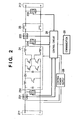
- Fig. 2 is a block diagram showing the internal structure of the inverter 20 used in this embodiment.
- An input terminal 211 receives a direct current power output from a solar battery module 10 described above.
- An output terminal 212 outputs the power converted into an alternative current power to a system or alternative current load.
- a DC-AC conversion circuit 24 includes a smoothing capacitor, reactor, diode, and switching elements.
- An interactive relay 25 turns on/off the alternative current output.
- An input voltage detector 232 detects the voltage input from the input terminal.
- An input current detector 231 detects the input current.
- An output voltage detector 234 detects the voltage which is DC-AC-converted by the DC-AC conversion circuit and to be output.
- An output current detector 233 detects the current to be output.
- a system voltage detector 235 detects the voltage of the power grid 30 connected to the output terminal.
- a control circuit 26 includes a microprocessor and the like.
- the control circuit 26 executes control (maximum power tracking control) to extract the maximum power from the solar battery array in accordance with the value of the voltage or current detected by the direct current voltage detector 232 or alternative current detector 231, control of the switching elements of the DC-AC conversion circuit, and coordination protection such as OV (Over Voltage), OF (Over Frequency), and islanding operation detection.
- a control power supply generation circuit 28 converts the output power from the solar battery module input from the input terminal into a predetermined voltage and supplies it as the control power supply to operate the control circuit.
- control circuit 26 a one-chip microcomputer is used. This microcomputer is formed by mounting the functions of a CPU, memory, A/D converter, 16-bit timer, and I/O ports in one chip. When external components such as a quartz oscillator and capacitor are connected, various kinds of control necessary for controlling the power converter can be executed.
- the control circuit 26 of this embodiment has two communication terminals 29 to mutually communicate with the plurality of inverters connected in parallel in the system.
- a master machine setting terminal is assigned as a terminal to set, of the plurality of inverters, a master machine for islanding operation detection, and a GND terminal is set as the GROUND of a signal.
- the master machine setting terminal is connected to a predetermined I/O port of the microcomputer. After the microcomputer is powered on, the master machine setting terminal is set as a read terminal by the initial setting operation of the program incorporated in the microcomputer.
- the GND terminal is connected to the digital signal GROUND terminal of the microcomputer.
- a form which uses a one-chip microcomputer as the control circuit 26 has been described above. Not only the form using the one-chip microcomputer but a circuit which combines discrete components, IC, and passive components can also be used.
- the operation of the inverter will be described next.
- the solar batteries generate no power.
- all inverters are inactive. In this case, no master machine is set yet.
- the solar battery modules are irradiated with sunlight, and output voltages from them rise.
- the control power supply of the inverter connected to the solar battery module is turned on.
- the microcomputer of the control circuit 26 When the control power supply is turned on, the microcomputer of the control circuit 26 is activated.
- the microcomputer reads out the program stored in advance in the ROM and executes initial setting.
- the master machine setting terminal is set as the read terminal, as described above.
- the output voltage from each solar battery module is monitored.
- the standby state is set until the output voltage exceeds the operation start voltage (activation voltage) of the inverter (step S101).
- step S103 When the output voltage from the solar battery module exceeds the activation voltage, it is confirmed first whether the state of the master machine setting terminal is Low (step S103). When no inverter is set as the master machine, all master machine setting terminals are Low. When the master machine setting terminal is Low, the inverter sets the I/O terminal of the connected microcomputer as a write terminal (step S104) and sets the output of the master machine setting terminal to High (step S105).
- inverter A whose solar battery module has reached the operation start voltage at the earliest timing is set as the master machine.
- the master machine setting terminal is always kept at High. Since the master machine setting terminal is already set to High, the remaining inverters connected can recognize that another inverter is set as the master machine.
- the inverter A sets the master flag to 1 in the control program (step S106) to set itself as the master machine which executes the islanding operation detection active schema and starts the inverter operation.
- the inverter (to be referred to as an "inverter B" hereinafter) which is activated next confirms the state of the master machine setting terminal (step S102) when it is determined in step S101 that the output voltage from the solar battery module B connected to the inverter exceeds the activation voltage. In this case, the terminal has already been set to High by the inverter A. Hence, the inverter B which reads the master machine setting terminal receives a High signal and recognizes that another inverter is set as the master machine. After that, the inverter B sets the slave flag to 1 in the control program (step S107) to set itself as a slave machine which does not execute the islanding operation detection active schema and starts the inverter operation.
- the inverter which is activated first is set as the master machine.
- the master machine which executes the islanding operation detection active schema is always present in the power generation system. Hence, any state in which the master machine is not operating due to a failure or the like in the system can be avoided, and a safer power generation system can be provided.
- a power generation system according to the second embodiment of the present invention will be described below.
- the system of the second embodiment is also a solar power generation system, as in the above-described first embodiment.
- a description of the same parts as in the first embodiment will be omitted, and characteristic parts of this embodiment will mainly be described.
- An inverter has nine communication terminals, as shown in Fig. 4 , to mutually communicate with remaining inverters connected in parallel.
- the data communication terminal and address communication terminal are connected to the serial communication port of the microcomputer.
- the data transmission request terminal, data transmission permission terminal, master machine setting terminal, reserve master machine setting terminal, and all inverter stop terminal are connected to the I/O ports of the microcomputer.
- the signal GND is connected to the I/O ports and the GND terminal of the microcomputer.
- the terminals connected to the I/O ports are set as a read terminal by the initial setting operation of the program incorporated in the microcomputer.
- each inverter stands by until the output voltage from the solar battery module exceeds the activation voltage (step S501).
- the state of the master machine setting terminal is confirmed (step S502).
- the master machine setting terminal is Low (YES in step S503), the inverter obtains the master right.
- the inverter sets the I/O terminal of the connected microcomputer as a write terminal (step S504) and sets the output of the master machine setting terminal to High (step S505).
- the inverter (to be referred to as an "inverter A" hereinafter) which is activated first is set as the master machine.
- the master machine setting terminal is kept at High.
- the solar battery modules of the remaining inverters connected reach the operation start voltage, and the states of the master machine setting terminals are confirmed, they are already High.
- the inverters can recognize that another inverter is already set as the master machine.
- the inverter A set as the master machine sets the master flag to 1 in the program (step S506) to set itself as the master machine which executes the islanding operation detection operation of active schema and starts the inverter operation.
- inverter B (to be referred to as an "inverter B" hereinafter) which is activated next will be described next.
- the inverter B also confirms the master machine setting terminal when the output voltage from the solar battery module exceeds the activation voltage (steps S501 and S502). In this case, the terminal has already been set to High by the inverter A. Hence, the inverter B which reads the master machine setting terminal receives a High signal (NO in step S503).
- the inverter B confirms the reserve master machine setting terminal (step S507). At this time point, no inverter is set as the reserve master machine yet. Hence, the terminal is Low (YES in step S508). When the reserve master machine setting terminal is Low, the inverter B obtains the reserve master right. The inverter sets the I/O terminal of the connected microcomputer as a write terminal (step S509) and sets the output of the reserve master machine setting terminal to High (step S510). The inverter B is set as the reserve master machine.
- the reserve master machine setting terminal is kept at High.
- the solar battery modules of the remaining inverters (inverters C to E) connected reach the activation voltage, and reserve master machine setting terminals are read, they are High.
- the inverters can recognize that another inverter is already set as the reserve master machine.
- the inverter B set as the reserve master machine sets the reserve master flag to 1 in the program (step S511) to set itself as the reserve master machine which executes the islanding operation detection operation of active schema when a failure occurs in the master machine, or the operation of the master machine stops due to shading and starts the inverter operation.
- the inverter B transmits the ID number of its own to the master machine through the data communication terminal to notify the master machine that the inverter B is set as the reserve master machine.
- inverter C The operation of the third inverter (to be referred to as an "inverter C" hereinafter) which is activated next will be described.
- the inverter C also confirms the master machine setting terminal when the output voltage from the solar battery module exceeds the activation voltage (steps S501 and S502). In this case, the terminal has already been set to High by the inverter A. Hence, the inverter C which reads the master machine setting terminal receives a High signal (NO in step S503). Next, the inverter C confirms the reserve master machine setting terminal (step S507). In this case as well, the terminal has already been set to High by the inverter B. Hence, the inverter C which reads the reserve master machine setting terminal receives a High signal (NO in step S508).
- the inverter C can recognize that other inverters are already set as the master machine and reserve master machine.
- the inverter C is set as a slave machine.
- the inverter C sets the slave flag to 1 in the program (step S512) to set itself as a slave machine which does not execute the islanding operation detection operation of active schema and starts the inverter operation.
- the inverter C transmits the ID number of its own to the master machine and reserve master machine through the data communication line to notify them that the inverter C has started operating as a slave machine.
- a High signal is output from the inverter (inverter A) set as the master machine to the master machine setting terminal.
- the reserve master machine inverter B
- the reserve master machine always monitors the state of the master machine setting terminal and grasps the operation state of the master machine.
- the state of the master machine setting terminal changes from High to Low.
- the reserve master machine can recognize that the master machine has stopped.
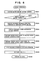
- the reserve master machine confirms the state of the master machine setting terminal (step S601). Upon confirming that output from the master machine setting terminal is Low (YES in step S602), and the master machine has stopped, the reserve master machine first executes the islanding operation detection operation of active schema as a temporary master machine (step S603) to maintain the safety of the power generation system. Then, the reserve master machine executes an operation of determining a new master machine.
- Each slave machine transmits the ID of its own to the reserve master machine at the start of inverter operation, as described above. For this reason, the reserve master machine knows the inverters currently connected to the power generation system as slave machines.
- the reserve master machine sequentially communicates with each inverter connected to the power generation system as a slave machine by using the data communication line, thereby collecting information of the currently generated power of each inverter (step S604).
- the reserve master machine compares the collected generated energies of the inverters and specifies the inverter having the highest generated power and the inverter having the second highest generated power. The generated power of the reserve master machine itself may also be compared.
- the reserve master machine selects the inverter having the highest generated power as the master machine and transmits the master right signal to the inverter selected as the master machine by using the data communication line (step S605). In addition, the reserve master machine selects the inverter having the second highest generated power as the reserve master machine and transmits the reserve master right signal by using the data communication line (step S606).
- the inverter selected as the master machine sets the I/O terminal of the microcomputer, which is connected to the master machine setting terminal, as a write terminal and sets the output of the master machine setting terminal to High. Then, the inverter sets the master flag to 1 in the program to set itself as the master machine which executes the islanding operation detection operation of active schema and starts the islanding operation detection operation.
- the inverter selected as the reserve master machine sets the I/O terminal of the microcomputer, which is connected to the reserve master machine setting terminal, as a write terminal and sets the output of the reserve master machine setting terminal to High. Then, the inverter sets the reserve master flag to 1 in the program to set itself as the reserve master machine which temporarily executes the islanding operation detection active schema when a failure occurs in the master machine and determines a new master machine and continue the operation.
- the inverter When the inverter which was set as the reserve master machine does not select itself as either the master machine or reserve master machine, the inverter sets the reserve master machine setting terminal to Low, stops the islanding operation detection operation of active schema (step S607), sets the I/O terminal of the microcomputer, which is connected to the reserve master machine setting terminal, as a read terminal, sets the slave flag to 1 in the program (step S608), and continues the operation as a slave machine which does not execute the islanding operation detection operation (step S609).
- a High signal is output from the inverter set as the reserve master machine to the reserve master machine setting terminal.
- the master machine always monitors the state of the reserve master machine setting terminal and grasps the state of the reserve master machine. When the reserve master machine stops, the state of the reserve master machine setting terminal changes from High to Low. Hence, by monitoring this terminal, the master machine can confirm that the reserve master machine has stopped.
- the master machine confirms the state of the reserve master machine setting terminal (step S701). Upon confirming that output from the reserve master machine setting terminal is Low (YES in step S702), and the reserve master machine has stopped, the master machine executes an operation of determining a new reserve master machine.
- Each slave machine transmits the ID of its own to the master machine at the start of inverter operation, as described above. For this reason, the master machine knows the inverters currently connected to the power generation system as slave machines.
- the master machine sequentially communicates with each inverter connected to the power generation system as a slave machine by using the data communication line, thereby collecting information of the currently generated power of each inverter (step S703).
- the master machine compares the collected generated energies of the inverters and specifies an inverter having the highest generated power.
- the master machine selects the inverter having the highest generated power as the reserve master machine and transmits the reserve master right signal to the inverter selected as the reserve master machine by using the data communication line (step S704).
- the inverter selected as the reserve master machine sets the I/O terminal of the microcomputer, which is connected to the reserve master machine setting terminal, as a write terminal and sets the output of the reserve master machine setting terminal to High. Then, the inverter sets the reserve master flag to 1 in the program to set itself as the reserve master machine which temporarily executes the islanding operation detection operation when a failure occurs in the master machine and determines a new master machine and continue the operation.
- the master machine and reserve master machine monitor each other's states. Even when one of them stops due to a failure or shading, any state in which the islanding operation detection operation is not executed in the power generation system can be avoided, and a safer power generation system can be provided.
- an inverter having the highest generated power i.e., an inverter which hardly stops operation is set as a new master machine, a stable power generation system can be provided.
- the inverters communicate with each other, and the reserve master machine or master machine sets the new master machine or reserve master machine.
- An administration apparatus such as a personal computer may separately be prepared. The administration apparatus may execute control to collect the information of each inverter and set the new master machine or reserve master machine.
- a power generation system according to the third embodiment of the present invention will be described below.
- the system of the third embodiment is also a solar power generation system, as in the above-described first and second embodiments.
- a description of the same parts as in the first and second embodiments will be omitted, and characteristic parts of this embodiment will mainly be described.
- inverters which are connected in parallel communicate with each other to set the master machine and reserve master machine, as in the second embodiment.
- the new master machine is set.
- the generated power of the master machine decreases, i.e., before the master machine stops, a new master machine is set.
- an inverter executes MPPT control to search for the maximum power point of a solar battery module.
- the inverter stops the MPPT control and executes a constant voltage operation at a predetermined voltage.
- the direct current voltage input to the inverter must be at least about 160 V.
- the inverter does not execute the MPPT control. Instead, the inverter starts the constant voltage operation mode with priority on maintaining the output voltage and executes setting such that a predetermined solar battery voltage of 160 V is obtained.
- the output voltage from the solar battery module decreases.
- the optimum operating voltage of the solar battery module decreases.
- the inverter switches to the constant voltage operation mode to operate the solar battery module at a constant voltage.
- the master machine communicates with each slave machine by using the data communication line, thereby collecting information of the generated power of each slave machine and sets an inverter having the highest generated power as a new master machine, as in the second embodiment described with reference to Fig. 6 .
- the inverter which has stopped serving as the master machine sets the master machine setting terminal of its own to Low and sets the I/O terminal of the microcomputer, which is connected to the master machine setting terminal, as a read terminal. Then, the inverter sets the master flag to 0 in the program to stop the islanding operation detection operation and operates as a slave machine.
- the inverter set as a new master machine sets the I/O terminal of the microcomputer, which is connected to the master machine setting terminal, as a write terminal and sets the output of the master machine setting terminal to High. Then, the inverter sets the master flag to 1 in the program, starts the islanding operation detection operation of active schema, and starts operating as a master machine.
- an inverter having the highest generated power in the slave machines may be set as a new reserve master machine.
- the master machine can be switched before it stops. Hence, any state in which islanding operation detection is not executed in the system can be avoided, and a safer power generation system can be provided.
- the present invention can be applied to a power generation system comprising a plurality of devices or to a management apparatus comprising a single device.
- the invention can be implemented by supplying a software program, which implements the functions of the foregoing embodiments (program codes corresponding to the above mentioned flowcharts of Fig. 1 , Fig. 2 and/or Figs. 5 to 7 ), directly or indirectly to a system or apparatus, reading the supplied program code with a computer of the system or apparatus, and then executing the program code.
- program codes corresponding to the above mentioned flowcharts of Fig. 1 , Fig. 2 and/or Figs. 5 to 7
- the mode of implementation need not rely upon a program.
- the program code installed in the computer also implements the present invention.
- the claims of the present invention also cover a computer program for the purpose of implementing the functions of the present invention.
- the program may be executed in any form, such as an object code, a program executed by an interpreter, or scrip data supplied to an operating system.
- Example of storage media that can be used for supplying the program are a floppy disk, a hard disk, an optical disk, a magneto-optical disk, a CD-ROM, a CD-R, a CD-RW, a magnetic tape, a non-volatile type memory card, a ROM, and a DVD (DVD-ROM and a DVD-R).
- a client computer can be connected to a website on the Internet using a browser of the client computer, and the computer program of the present invention or an automatically-installable compressed file of the program can be downloaded to a recording medium such as a hard disk.
- the program of the present invention can be supplied by dividing the program code constituting the program into a plurality of files and downloading the files from different websites.
- a WWW World Wide Web
- a storage medium such as a CD-ROM
- an operating system or the like running on the computer may perform all or a part of the actual processing so that the functions of the foregoing embodiments can be implemented by this processing.
- a CPU or the like mounted on the function expansion board or function expansion unit performs all or a part of the actual processing so that the functions of the foregoing embodiments can be implemented by this processing.
Claims (13)
- Système de production de puissance incluant une pluralité d'ensembles de sources (10A - 10E) de puissance à courant direct et de convertisseurs (20A - 20E) de puissance qui sont raccordés aux sources de puissance à courant direct afin de convertir une puissance à courant direct en une puissance à courant alternatif, les convertisseurs de puissance étant raccordés en parallèle pour fournir la puissance à courant alternatif à une alimentation (30) de système, constitué :d'un moyen (26) d'établissement d'état de fonctionnement destiné à établir, à partir des convertisseurs (20A - 20E) de puissance, un convertisseur de puissance en tant que machine maître qui est conçue pour détecter un état de fonctionnement en îlot dans lequel une alimentation en provenance de l'alimentation de système est stoppée, et pour exécuter un établissement de sorte à provoquer une non-détection de l'état de fonctionnement en îlot par les convertisseurs de puissance restants,dans lequel, lorsque la machine maître n'est pas présente parmi les convertisseurs de puissance en fonctionnement, ledit moyen (26) d'établissement d'état de fonctionnement est conçu pour sélectionner une autre machine maître à partir des convertisseurs de puissance en fonctionnement conformément à une condition prédéterminée, et caractérisé en ce queledit moyen (26) d'établissement d'état de fonctionnement est conçu pour établir par avance une machine maître de réserve qui fonctionne en tant que l'autre machine maître lorsque la machine maître n'est pas présente parmi les convertisseurs de puissance en fonctionnement.
- Système selon la revendication 1, caractérisé en ce que chaque convertisseur (20A - 20E) de puissance est constitué d'un moyen (29) de communication, et en ce que le convertisseur de puissance établi en tant que la machine maître transmet, aux convertisseurs de puissance restants en utilisant ledit moyen de communication un signal prédéterminé représentant que le convertisseur de puissance est établi en tant que la machine maître.
- Système selon la revendication 1, caractérisé en ce que chaque convertisseur (20A - 20E) de puissance est constitué dudit moyen (26) d'établissement d'état de fonctionnement, et en ce qu'au moins l'un des convertisseurs de puissance, excepté la machine maître, surveille un état de la machine maître.
- Système selon l'une quelconque des revendications 1 à 3, caractérisé en ce que la condition prédéterminée est un ordre de démarrage de fonctionnement.
- Système selon l'une quelconque des revendications 1 à 3, caractérisé en ce que la condition prédéterminée est un multiple d'une puissance de sortie.
- Système selon la revendication 1, caractérisé en ce que chaque convertisseur (20A - 20E) de puissance est constitué dudit moyen (26) d'établissement d'état de fonctionnement, et en ce que la machine maître ainsi que la machine maître de réserve surveillent les états de l'une et de l'autre.
- Système selon l'une quelconque des revendications 1 à 6, caractérisé en ce que les convertisseurs (20A - 20E) de puissance ont au moins deux modes de fonctionnement incluant un mode de fonctionnement à commande de puissance maximum ainsi qu'un mode de fonctionnement à tension constante, et en ce que ledit moyen d'établissement d'état de fonctionnement établit que le convertisseur de puissance fonctionne en tant que l'autre machine maître lorsque la machine maître commute du mode de fonctionnement à commande de puissance maximum vers le mode de fonctionnement à tension constante.
- Système selon l'une quelconque des revendications 1 à 7, caractérisé en ce que la détection de l'état de fonctionnement en îlot est faite par un schéma actif.
- Système selon l'une quelconque des revendications 1 à 8, caractérisé en ce que la source (10A - 10E) de puissance à courant direct inclut une batterie solaire.
- Dispositif d'administration d'un système de production de puissance incluant une pluralité d'ensembles de sources (10A - 10E) de puissance à courant direct et de convertisseurs (20A - 20E) de puissance qui sont raccordés aux sources de puissance à courant direct afin de convertir une puissance à courant direct en une puissance à courant alternatif, les convertisseurs de puissance étant raccordés en parallèle pour fournir la puissance à courant alternatif à une alimentation (30) de système, où
à partir des convertisseurs (20A - 20E) de puissance, un convertisseur de puissance est établi en tant qu'une machine maître qui détecte un état de fonctionnement en îlot dans lequel une alimentation en provenance de l'alimentation de système est stoppée, et un établissement est exécuté de sorte à provoquer une non-détection de l'état de fonctionnement en îlot par les convertisseurs de puissance restants, et
lorsque la machine maître n'est pas présente parmi les convertisseurs de puissance en fonctionnement, une autre machine maître est sélectionnée à partir des convertisseurs de puissance en fonctionnement conformément à une condition prédéterminée, et caractérisé en ce que
une machine maître de réserve est établie par avance et elle fonctionne en tant que l'autre machine maître lorsque la machine maître n'est pas présente parmi les convertisseurs de puissance en fonctionnement. - Procédé d'administration d'un système de production de puissance incluant une pluralité d'ensembles de sources de puissance à courant direct et de convertisseurs de puissance qui sont raccordés aux sources de puissance à courant direct pour convertir une puissance à courant direct en une puissance à courant alternatif, les convertisseurs de puissance étant raccordés en parallèle pour fournir la puissance de courant alternatif à une alimentation de système, constitué :d'une étape d'établissement destinée à établir, à partir des convertisseurs de puissance, un convertisseur de puissance en tant qu'une machine maître qui détecte un état de fonctionnement en îlot dans lequel une alimentation en provenance de l'alimentation de système est stoppée, et à exécuter un établissement de sorte à provoquer une non-détection de l'état de fonctionnement en îlot par les convertisseurs de puissance restants, etd'une étape de sélection consistant à sélectionner, lorsque la machine maître n'est pas présente parmi les convertisseurs de puissance en fonctionnement, une autre machine maître à partir des convertisseurs de puissance en fonctionnement conformément à une condition prédéterminée, et caractérisé parune étape d'établissement supplémentaire destinée à établir par avance une machine maître de réserve qui fonctionne en tant que l'autre machine maître lorsque la machine maître n'est pas présente parmi les convertisseurs de puissance en fonctionnement.
- Programme informatique provoquant la mise en oeuvre par un dispositif d'ordinateur d'un procédé d'administration de système de production de puissance selon la revendication 11.
- Support de stockage stockant un programme informatique selon la revendication 12.
Applications Claiming Priority (2)
| Application Number | Priority Date | Filing Date | Title |
|---|---|---|---|
| JP2004085237 | 2004-03-23 | ||
| JP2004085237A JP4217644B2 (ja) | 2004-03-23 | 2004-03-23 | 発電システム、発電システムの管理装置及び管理方法 |
Publications (2)
| Publication Number | Publication Date |
|---|---|
| EP1580862A1 EP1580862A1 (fr) | 2005-09-28 |
| EP1580862B1 true EP1580862B1 (fr) | 2008-07-30 |
Family
ID=34858413
Family Applications (1)
| Application Number | Title | Priority Date | Filing Date |
|---|---|---|---|
| EP20050006140 Expired - Fee Related EP1580862B1 (fr) | 2004-03-23 | 2005-03-21 | Commande master/slave des modules reliés parallèles de batterie solaire |
Country Status (4)
| Country | Link |
|---|---|
| US (1) | US7456523B2 (fr) |
| EP (1) | EP1580862B1 (fr) |
| JP (1) | JP4217644B2 (fr) |
| DE (1) | DE602005008501D1 (fr) |
Cited By (2)
| Publication number | Priority date | Publication date | Assignee | Title |
|---|---|---|---|---|
| CN102545207A (zh) * | 2011-12-22 | 2012-07-04 | 河海大学 | 基于预测-校正内点法的vsc-hvdc交直流最优潮流方法 |
| CN103795091A (zh) * | 2014-01-14 | 2014-05-14 | 河海大学 | 基于预测校正内点法的混合直流输电系统最优潮流方法 |
Families Citing this family (145)
| Publication number | Priority date | Publication date | Assignee | Title |
|---|---|---|---|---|
| JP4365332B2 (ja) * | 2005-02-17 | 2009-11-18 | 大阪瓦斯株式会社 | 発電設備の単独運転検出装置 |
| US10693415B2 (en) | 2007-12-05 | 2020-06-23 | Solaredge Technologies Ltd. | Testing of a photovoltaic panel |
| US11881814B2 (en) | 2005-12-05 | 2024-01-23 | Solaredge Technologies Ltd. | Testing of a photovoltaic panel |
| US7565968B2 (en) * | 2006-03-13 | 2009-07-28 | Lindley Michael B | Portable survival kit |
| JP2008059084A (ja) * | 2006-08-29 | 2008-03-13 | Toshiba Kyaria Kk | 系統連系インバータ |
| JP2008079407A (ja) * | 2006-09-20 | 2008-04-03 | Toshiba Fuel Cell Power Systems Corp | 単独運転防止装置及び方法 |
| US8751053B2 (en) * | 2006-10-19 | 2014-06-10 | Tigo Energy, Inc. | Method and system to provide a distributed local energy production system with high-voltage DC bus |
| US9112379B2 (en) | 2006-12-06 | 2015-08-18 | Solaredge Technologies Ltd. | Pairing of components in a direct current distributed power generation system |
| US11728768B2 (en) | 2006-12-06 | 2023-08-15 | Solaredge Technologies Ltd. | Pairing of components in a direct current distributed power generation system |
| US11296650B2 (en) | 2006-12-06 | 2022-04-05 | Solaredge Technologies Ltd. | System and method for protection during inverter shutdown in distributed power installations |
| US8013472B2 (en) | 2006-12-06 | 2011-09-06 | Solaredge, Ltd. | Method for distributed power harvesting using DC power sources |
| US8618692B2 (en) | 2007-12-04 | 2013-12-31 | Solaredge Technologies Ltd. | Distributed power system using direct current power sources |
| US8319471B2 (en) | 2006-12-06 | 2012-11-27 | Solaredge, Ltd. | Battery power delivery module |
| US11309832B2 (en) | 2006-12-06 | 2022-04-19 | Solaredge Technologies Ltd. | Distributed power harvesting systems using DC power sources |
| US8963369B2 (en) | 2007-12-04 | 2015-02-24 | Solaredge Technologies Ltd. | Distributed power harvesting systems using DC power sources |
| US8473250B2 (en) | 2006-12-06 | 2013-06-25 | Solaredge, Ltd. | Monitoring of distributed power harvesting systems using DC power sources |
| US11569659B2 (en) | 2006-12-06 | 2023-01-31 | Solaredge Technologies Ltd. | Distributed power harvesting systems using DC power sources |
| US11888387B2 (en) | 2006-12-06 | 2024-01-30 | Solaredge Technologies Ltd. | Safety mechanisms, wake up and shutdown methods in distributed power installations |
| US9130401B2 (en) | 2006-12-06 | 2015-09-08 | Solaredge Technologies Ltd. | Distributed power harvesting systems using DC power sources |
| US11855231B2 (en) | 2006-12-06 | 2023-12-26 | Solaredge Technologies Ltd. | Distributed power harvesting systems using DC power sources |
| US9088178B2 (en) | 2006-12-06 | 2015-07-21 | Solaredge Technologies Ltd | Distributed power harvesting systems using DC power sources |
| US11735910B2 (en) | 2006-12-06 | 2023-08-22 | Solaredge Technologies Ltd. | Distributed power system using direct current power sources |
| US8319483B2 (en) | 2007-08-06 | 2012-11-27 | Solaredge Technologies Ltd. | Digital average input current control in power converter |
| US11687112B2 (en) | 2006-12-06 | 2023-06-27 | Solaredge Technologies Ltd. | Distributed power harvesting systems using DC power sources |
| US8947194B2 (en) | 2009-05-26 | 2015-02-03 | Solaredge Technologies Ltd. | Theft detection and prevention in a power generation system |
| US8816535B2 (en) | 2007-10-10 | 2014-08-26 | Solaredge Technologies, Ltd. | System and method for protection during inverter shutdown in distributed power installations |
| US8384243B2 (en) | 2007-12-04 | 2013-02-26 | Solaredge Technologies Ltd. | Distributed power harvesting systems using DC power sources |
| US20110005567A1 (en) * | 2007-04-06 | 2011-01-13 | Sunovia Energy Technologies Inc. | Modular solar panel system |
| DE102007022879A1 (de) * | 2007-05-14 | 2008-11-27 | Sma Solar Technology Ag | Wechselrichter zur Netzeinspeisung in ein Wechselstromnetz |
| US20090020151A1 (en) * | 2007-07-16 | 2009-01-22 | Pvi Solutions, Inc. | Method and apparatus for converting a direct current to alternating current utilizing a plurality of inverters |
| US7755916B2 (en) | 2007-10-11 | 2010-07-13 | Solarbridge Technologies, Inc. | Methods for minimizing double-frequency ripple power in single-phase power conditioners |
| JP5059556B2 (ja) * | 2007-11-08 | 2012-10-24 | ニチコン株式会社 | 電力供給装置 |
| US9291696B2 (en) | 2007-12-05 | 2016-03-22 | Solaredge Technologies Ltd. | Photovoltaic system power tracking method |
| US8049523B2 (en) | 2007-12-05 | 2011-11-01 | Solaredge Technologies Ltd. | Current sensing on a MOSFET |
| EP2232690B1 (fr) | 2007-12-05 | 2016-08-31 | Solaredge Technologies Ltd. | Onduleurs connectés en parallèle |
| US11264947B2 (en) | 2007-12-05 | 2022-03-01 | Solaredge Technologies Ltd. | Testing of a photovoltaic panel |
| CN101933209B (zh) | 2007-12-05 | 2015-10-21 | 太阳能安吉有限公司 | 分布式电力装置中的安全机构、醒来和关闭方法 |
| WO2009118682A2 (fr) | 2008-03-24 | 2009-10-01 | Solaredge Technolgies Ltd. | Commutation sous intensité nulle |
| WO2009146065A2 (fr) * | 2008-04-04 | 2009-12-03 | Harrington Francis P | Module d'interface d'énergie et système de conversion de puissance |
| WO2009136358A1 (fr) | 2008-05-05 | 2009-11-12 | Solaredge Technologies Ltd. | Circuit combinateur de puissance de courant continu |
| US8625315B2 (en) * | 2008-05-09 | 2014-01-07 | Etm Electromatic Inc | Inverter modulator with variable switching frequency |
| JP5406470B2 (ja) * | 2008-06-20 | 2014-02-05 | キヤノン株式会社 | バッファ駆動装置 |
| US8098055B2 (en) * | 2008-08-01 | 2012-01-17 | Tigo Energy, Inc. | Step-up converter systems and methods |
| EP2189859A1 (fr) * | 2008-11-21 | 2010-05-26 | SMA Solar Technology AG | Installation de production d'énergie dotée plusieurs de générateurs de courant équipés de convertisseurs, par exemple, installations PV et/ou éoliennes |
| US8279642B2 (en) | 2009-07-31 | 2012-10-02 | Solarbridge Technologies, Inc. | Apparatus for converting direct current to alternating current using an active filter to reduce double-frequency ripple power of bus waveform |
| JP4823345B2 (ja) | 2009-09-18 | 2011-11-24 | 三菱重工業株式会社 | 電池システム |
| US8207637B2 (en) * | 2009-10-09 | 2012-06-26 | Solarbridge Technologies, Inc. | System and apparatus for interconnecting an array of power generating assemblies |
| US8462518B2 (en) | 2009-10-12 | 2013-06-11 | Solarbridge Technologies, Inc. | Power inverter docking system for photovoltaic modules |
| US8334618B2 (en) * | 2009-11-13 | 2012-12-18 | Eaton Corporation | Method and area electric power system detecting islanding by employing controlled reactive power injection by a number of inverters |
| US8710699B2 (en) | 2009-12-01 | 2014-04-29 | Solaredge Technologies Ltd. | Dual use photovoltaic system |
| US8824178B1 (en) | 2009-12-31 | 2014-09-02 | Solarbridge Technologies, Inc. | Parallel power converter topology |
| CN102118043B (zh) * | 2009-12-31 | 2013-12-04 | 比亚迪股份有限公司 | 用于对动力电池充电的太阳能充电器 |
| JP5737660B2 (ja) | 2010-01-25 | 2015-06-17 | エンフェイズ エナジー インコーポレイテッド | 分散型電力源を相互接続するための方法及び装置 |
| US9806445B2 (en) | 2010-01-25 | 2017-10-31 | Enphase Energy, Inc. | Method and apparatus for interconnecting distributed power sources |
| US8766696B2 (en) | 2010-01-27 | 2014-07-01 | Solaredge Technologies Ltd. | Fast voltage level shifter circuit |
| US8837097B2 (en) * | 2010-06-07 | 2014-09-16 | Eaton Corporation | Protection, monitoring or indication apparatus for a direct current electrical generating apparatus or a plurality of strings |
| DE102010026299A1 (de) * | 2010-07-06 | 2012-01-12 | Phoenix Contact Gmbh & Co. Kg | Verfahren zur Steuerung von PV-Anlagen in einem Stromversorgungsnetz |
| JP5585288B2 (ja) * | 2010-08-10 | 2014-09-10 | 株式会社明電舎 | 風力発電システム及び風力発電システムの発電出力スケジュール制御方法 |
| JP5539099B2 (ja) | 2010-08-13 | 2014-07-02 | キヤノン株式会社 | 磁気勾配計、および磁気センシング方法 |
| US9160408B2 (en) | 2010-10-11 | 2015-10-13 | Sunpower Corporation | System and method for establishing communication with an array of inverters |
| US8279649B2 (en) | 2010-10-11 | 2012-10-02 | Solarbridge Technologies, Inc. | Apparatus and method for controlling a power inverter |
| US8503200B2 (en) | 2010-10-11 | 2013-08-06 | Solarbridge Technologies, Inc. | Quadrature-corrected feedforward control apparatus and method for DC-AC power conversion |
| US10230310B2 (en) | 2016-04-05 | 2019-03-12 | Solaredge Technologies Ltd | Safety switch for photovoltaic systems |
| GB2485527B (en) | 2010-11-09 | 2012-12-19 | Solaredge Technologies Ltd | Arc detection and prevention in a power generation system |
| US10673229B2 (en) | 2010-11-09 | 2020-06-02 | Solaredge Technologies Ltd. | Arc detection and prevention in a power generation system |
| US10673222B2 (en) | 2010-11-09 | 2020-06-02 | Solaredge Technologies Ltd. | Arc detection and prevention in a power generation system |
| US9118213B2 (en) | 2010-11-24 | 2015-08-25 | Kohler Co. | Portal for harvesting energy from distributed electrical power sources |
| US8842454B2 (en) | 2010-11-29 | 2014-09-23 | Solarbridge Technologies, Inc. | Inverter array with localized inverter control |
| US9467063B2 (en) | 2010-11-29 | 2016-10-11 | Sunpower Corporation | Technologies for interleaved control of an inverter array |
| GB2486408A (en) | 2010-12-09 | 2012-06-20 | Solaredge Technologies Ltd | Disconnection of a string carrying direct current |
| KR101208252B1 (ko) * | 2010-12-21 | 2012-12-04 | 성균관대학교산학협력단 | 태양에너지 발전시스템의 최대전력점 추종을 위한 전류 지령치 생성방법 및 장치 |
| DE102011007929B4 (de) * | 2011-01-03 | 2015-06-11 | Sma Solar Technology Ag | Verfahren zum Betrieb eines Wechselrichters und Steuereinrichtung |
| GB2483317B (en) | 2011-01-12 | 2012-08-22 | Solaredge Technologies Ltd | Serially connected inverters |
| US9043039B2 (en) * | 2011-02-24 | 2015-05-26 | Tigo Energy, Inc. | System and method for arc detection and intervention in solar energy systems |
| US8193788B2 (en) | 2011-04-27 | 2012-06-05 | Solarbridge Technologies, Inc. | Method and device for controlling a configurable power supply to provide AC and/or DC power output |
| US9065354B2 (en) | 2011-04-27 | 2015-06-23 | Sunpower Corporation | Multi-stage power inverter for power bus communication |
| US8611107B2 (en) | 2011-04-27 | 2013-12-17 | Solarbridge Technologies, Inc. | Method and system for controlling a multi-stage power inverter |
| EP2665618B1 (fr) * | 2011-05-04 | 2020-11-04 | Siemens Aktiengesellschaft | Procédé et dispositif de fourniture d'énergie électrique |
| FR2976541B1 (fr) * | 2011-06-15 | 2013-06-14 | Renault Sa | Procede et systeme de commande de gestion de l'alimentation electrique d'un vehicule apres arret du groupe motopropulseur |
| JP5646752B2 (ja) * | 2011-06-28 | 2014-12-24 | 京セラ株式会社 | 系統連系インバータ装置およびその制御方法 |
| US8922185B2 (en) | 2011-07-11 | 2014-12-30 | Solarbridge Technologies, Inc. | Device and method for global maximum power point tracking |
| US8570005B2 (en) | 2011-09-12 | 2013-10-29 | Solaredge Technologies Ltd. | Direct current link circuit |
| US8284574B2 (en) | 2011-10-17 | 2012-10-09 | Solarbridge Technologies, Inc. | Method and apparatus for controlling an inverter using pulse mode control |
| KR101868350B1 (ko) * | 2011-10-26 | 2018-06-19 | 엘지전자 주식회사 | 태양광발전장치 및 이의 운전방법 |
| FR2982099B1 (fr) | 2011-10-27 | 2013-11-15 | St Microelectronics Tours Sas | Commande d'un interrupteur dans un convertisseur de puissance |
| GB2498365A (en) | 2012-01-11 | 2013-07-17 | Solaredge Technologies Ltd | Photovoltaic module |
| GB2498791A (en) | 2012-01-30 | 2013-07-31 | Solaredge Technologies Ltd | Photovoltaic panel circuitry |
| US9853565B2 (en) | 2012-01-30 | 2017-12-26 | Solaredge Technologies Ltd. | Maximized power in a photovoltaic distributed power system |
| GB2498790A (en) | 2012-01-30 | 2013-07-31 | Solaredge Technologies Ltd | Maximising power in a photovoltaic distributed power system |
| TWI449295B (zh) * | 2012-02-08 | 2014-08-11 | Darfon Electronics Corp | 離網型主從式太陽能換流器系統及其控制方法 |
| US8941377B2 (en) | 2012-02-10 | 2015-01-27 | Canon Kabushiki Kaisha | Optically pumped magnetometer and magnetic sensing method |
| GB2499991A (en) | 2012-03-05 | 2013-09-11 | Solaredge Technologies Ltd | DC link circuit for photovoltaic array |
| JP5414001B2 (ja) * | 2012-03-09 | 2014-02-12 | Necインフロンティア株式会社 | キャッシュ情報交換方法、キャッシュ情報交換システム及び代理装置 |
| US9964609B2 (en) | 2012-04-18 | 2018-05-08 | Canon Kabushiki Kaisha | Optically pumped magnetometer |
| EP3499695A1 (fr) | 2012-05-25 | 2019-06-19 | Solaredge Technologies Ltd. | Circuit pour sources interconnectées de courant continu |
| US10115841B2 (en) | 2012-06-04 | 2018-10-30 | Solaredge Technologies Ltd. | Integrated photovoltaic panel circuitry |
| USD708143S1 (en) | 2012-06-07 | 2014-07-01 | Enphase Energy, Inc. | Drop cable connector |
| USD707632S1 (en) | 2012-06-07 | 2014-06-24 | Enphase Energy, Inc. | Trunk connector |
| US9276635B2 (en) | 2012-06-29 | 2016-03-01 | Sunpower Corporation | Device, system, and method for communicating with a power inverter using power line communications |
| JP2014023211A (ja) * | 2012-07-13 | 2014-02-03 | Denso Corp | 充電装置 |
| WO2014059236A1 (fr) * | 2012-10-11 | 2014-04-17 | Windstrip Llc | Système d'alimentation hybride à entrées multiples et sortie unique |
| US8648498B1 (en) * | 2012-11-19 | 2014-02-11 | Renewable Power Conversion, Inc | Photovoltaic power system with distributed photovoltaic string to polyphase AC power converters |
| JP6097947B2 (ja) * | 2012-11-30 | 2017-03-22 | 株式会社Tbk | 発電システム及びその制御方法 |
| US9620994B2 (en) | 2013-01-17 | 2017-04-11 | Eaton Corporation | Method and system of anti-islanding of a microgrid in a grid-connected microgrid system |
| WO2014115557A1 (fr) * | 2013-01-28 | 2014-07-31 | 日本電気株式会社 | Routeur d'énergie et procédé de commande du fonctionnement de celui-ci, système de réseau d'énergie et support non temporaire lisible par ordinateur stockant un programme |
| US9548619B2 (en) | 2013-03-14 | 2017-01-17 | Solaredge Technologies Ltd. | Method and apparatus for storing and depleting energy |
| US9941813B2 (en) | 2013-03-14 | 2018-04-10 | Solaredge Technologies Ltd. | High frequency multi-level inverter |
| US9584044B2 (en) | 2013-03-15 | 2017-02-28 | Sunpower Corporation | Technologies for converter topologies |
| US9564835B2 (en) | 2013-03-15 | 2017-02-07 | Sunpower Corporation | Inverter communications using output signal |
| EP3506370B1 (fr) | 2013-03-15 | 2023-12-20 | Solaredge Technologies Ltd. | Mécanisme de dérivation |
| DE102013205427A1 (de) * | 2013-03-27 | 2014-10-16 | Siemens Aktiengesellschaft | Einspeisevorrichtung zum Einspeisen von elektrischem Strom in ein Stromnetz sowie Verfahren zum Betreiben einer solchen Einspeisevorrichtung |
| CN103236716A (zh) * | 2013-05-13 | 2013-08-07 | 浙江昱能光伏科技集成有限公司 | 离网型的直流转交流系统 |
| JP6113615B2 (ja) * | 2013-09-19 | 2017-04-12 | 株式会社東芝 | 制御装置、電力変換装置、制御方法、プログラム及び制御システム |
| WO2015058791A1 (fr) * | 2013-10-22 | 2015-04-30 | Abb Technology Ltd | Procédé permettant de commander la puissance électrique dans un microréseau et agencement comprenant des générateurs distribués |
| JP6229458B2 (ja) * | 2013-11-26 | 2017-11-15 | 株式会社ノーリツ | 発電システム |
| CN103647297B (zh) * | 2013-12-11 | 2015-12-02 | 上海电机学院 | 一种风光互补发电分散储能控制电路 |
| JP6257339B2 (ja) * | 2014-01-15 | 2018-01-10 | キヤノン株式会社 | 給電システム及び情報処理方法 |
| UA107542C2 (uk) | 2014-01-24 | 2015-01-12 | Товариство З Обмеженою Відповідальністю "Техінвест-Еко" | Спосіб та пристрій для відбору електричної енергії від фотоелектричного модуля |
| US9318974B2 (en) | 2014-03-26 | 2016-04-19 | Solaredge Technologies Ltd. | Multi-level inverter with flying capacitor topology |
| US20150288183A1 (en) | 2014-04-06 | 2015-10-08 | CleanSpark Technologies LLC | Establishing communication and power sharing links between components of a distributed energy system |
| JP6289270B2 (ja) * | 2014-05-29 | 2018-03-07 | 三菱電機株式会社 | 電力供給システム及びパワーコンディショナ |
| JP6391370B2 (ja) | 2014-08-29 | 2018-09-19 | キヤノン株式会社 | 光ポンピング磁力計及び磁気センシング方法 |
| JPWO2016047095A1 (ja) * | 2014-09-26 | 2017-07-06 | パナソニックIpマネジメント株式会社 | 電源装置 |
| JP6517494B2 (ja) | 2014-10-30 | 2019-05-22 | 株式会社東芝 | 電力変換装置、制御方法およびコンピュータプログラム |
| CN105743136B (zh) * | 2014-12-11 | 2017-12-22 | 南京南瑞继保电气有限公司 | 一种孤岛状态下抑制多个换流站进入无源控制模式的方法 |
| JP2016187290A (ja) * | 2015-03-27 | 2016-10-27 | パナソニックIpマネジメント株式会社 | 電力供給システム及び電力変換装置 |
| US10374424B2 (en) | 2015-08-18 | 2019-08-06 | Argentum Electronics, Inc. | Wide range power distribution systems and methods |
| WO2017029628A1 (fr) | 2015-08-18 | 2017-02-23 | Argentum Electronics, Inc. | Combineur de puissance à large plage |
| JPWO2017038061A1 (ja) * | 2015-09-01 | 2018-07-19 | パナソニックIpマネジメント株式会社 | 燃料電池システム及びその集合体 |
| CN105162165A (zh) * | 2015-09-24 | 2015-12-16 | 华南理工大学 | 一种变流器集散化改造的双馈异步发电系统 |
| CN105186567B (zh) * | 2015-09-24 | 2017-10-20 | 华南理工大学 | 一种故障时不停机的变速恒频发电系统 |
| US10599113B2 (en) | 2016-03-03 | 2020-03-24 | Solaredge Technologies Ltd. | Apparatus and method for determining an order of power devices in power generation systems |
| US11081608B2 (en) | 2016-03-03 | 2021-08-03 | Solaredge Technologies Ltd. | Apparatus and method for determining an order of power devices in power generation systems |
| CN107153212B (zh) | 2016-03-03 | 2023-07-28 | 太阳能安吉科技有限公司 | 用于映射发电设施的方法 |
| US11018623B2 (en) | 2016-04-05 | 2021-05-25 | Solaredge Technologies Ltd. | Safety switch for photovoltaic systems |
| US11177663B2 (en) | 2016-04-05 | 2021-11-16 | Solaredge Technologies Ltd. | Chain of power devices |
| US10418817B2 (en) | 2016-07-29 | 2019-09-17 | Cummins Power Generation Ip, Inc. | Synchronization of parallel gensets with source arbitration |
| US10291028B2 (en) | 2016-07-29 | 2019-05-14 | Cummins Power Generation Ip, Inc. | Masterless distributed power transfer control |
| JP2019084601A (ja) | 2017-11-02 | 2019-06-06 | キヤノン株式会社 | 情報処理装置、把持システムおよび情報処理方法 |
| JP2019092275A (ja) * | 2017-11-14 | 2019-06-13 | 株式会社日立製作所 | 電力管理システム |
| JP6638848B1 (ja) * | 2019-07-04 | 2020-01-29 | 富士電機株式会社 | 電力変換装置、制御装置、サーバ、およびシステム |
| KR20210108464A (ko) * | 2019-09-05 | 2021-09-02 | 도시바 미쓰비시덴키 산교시스템 가부시키가이샤 | 무정전 전원 시스템 |
| CN111244975B (zh) * | 2020-03-09 | 2021-07-30 | 特变电工西安电气科技有限公司 | 一种基于主从微电网系统离网运行模式的稳定控制方法 |
| KR102549305B1 (ko) * | 2022-04-12 | 2023-06-30 | 리얼테크(주) | 마이크로그리드 시스템 및 그 제어 방법 |
| CN114690840B (zh) * | 2022-05-31 | 2022-09-02 | 深圳戴普森新能源技术有限公司 | 带有前置功率监测并进行平衡的mppt控制系统 |
Family Cites Families (9)
| Publication number | Priority date | Publication date | Assignee | Title |
|---|---|---|---|---|
| JPH08147890A (ja) * | 1994-11-21 | 1996-06-07 | Canon Inc | 記録再生装置 |
| CN1161678C (zh) | 1998-03-30 | 2004-08-11 | 三洋电机株式会社 | 太阳能发电装置 |
| JP3876562B2 (ja) | 1999-03-16 | 2007-01-31 | Jfeスチール株式会社 | 自然エネルギ発電装置の系統連係方法 |
| JP2000305634A (ja) | 1999-04-20 | 2000-11-02 | Sanyo Electric Co Ltd | 系統連系システム |
| US6285572B1 (en) | 1999-04-20 | 2001-09-04 | Sanyo Electric Co., Ltd. | Method of operating a power supply system having parallel-connected inverters, and power converting system |
| US6396170B1 (en) * | 2000-03-29 | 2002-05-28 | Powerware Corporation | Method and apparatus for coordinating uninterruptible power supply modules to provide scalable, redundant power |
| US6522030B1 (en) * | 2000-04-24 | 2003-02-18 | Capstone Turbine Corporation | Multiple power generator connection method and system |
| US7000049B1 (en) * | 2000-12-28 | 2006-02-14 | Juniper Networks, Inc. | Systems and methods for reliably selecting bus mastership in a fault tolerant manner |
| JP2004208494A (ja) * | 2002-12-11 | 2004-07-22 | Canon Inc | 信号発生器の制御方法 |
-
2004
- 2004-03-23 JP JP2004085237A patent/JP4217644B2/ja not_active Expired - Fee Related
-
2005
- 2005-03-21 DE DE200560008501 patent/DE602005008501D1/de active Active
- 2005-03-21 US US11/084,044 patent/US7456523B2/en not_active Expired - Fee Related
- 2005-03-21 EP EP20050006140 patent/EP1580862B1/fr not_active Expired - Fee Related
Cited By (3)
| Publication number | Priority date | Publication date | Assignee | Title |
|---|---|---|---|---|
| CN102545207A (zh) * | 2011-12-22 | 2012-07-04 | 河海大学 | 基于预测-校正内点法的vsc-hvdc交直流最优潮流方法 |
| CN102545207B (zh) * | 2011-12-22 | 2014-08-06 | 河海大学 | 基于预测-校正内点法的vsc-hvdc交直流最优潮流方法 |
| CN103795091A (zh) * | 2014-01-14 | 2014-05-14 | 河海大学 | 基于预测校正内点法的混合直流输电系统最优潮流方法 |
Also Published As
| Publication number | Publication date |
|---|---|
| US20050213272A1 (en) | 2005-09-29 |
| US7456523B2 (en) | 2008-11-25 |
| JP4217644B2 (ja) | 2009-02-04 |
| EP1580862A1 (fr) | 2005-09-28 |
| DE602005008501D1 (de) | 2008-09-11 |
| JP2005278257A (ja) | 2005-10-06 |
Similar Documents
| Publication | Publication Date | Title |
|---|---|---|
| EP1580862B1 (fr) | Commande master/slave des modules reliés parallèles de batterie solaire | |
| US9041252B2 (en) | Advanced renewable energy harvesting | |
| US6801442B2 (en) | Power conversion apparatus, power conversion system, and islanding operation detection method | |
| Wang et al. | Design considerations of sub-mW indoor light energy harvesting for wireless sensor systems | |
| KR101295529B1 (ko) | 태양전지판의 고장진단 원격감시 시스템 | |
| JP2004147465A (ja) | 変換装置 | |
| JP6236582B2 (ja) | 適合するしきい値を有する太陽電池の電子的管理システム | |
| AU2002329062A1 (en) | Power conversion apparatus, power conversion system, and islanding operation detection method | |
| CN101523230A (zh) | 太阳能逆变器以及用于将太阳能转换成电能的装置 | |
| JP2010186795A (ja) | 光電池装置、および故障判定方法 | |
| AU2018278210B2 (en) | Maximum power point tracking hybrid control of an energy storage system | |
| KR20070009497A (ko) | 절연형 직류발전 모듈이 구성된 태양광 발전장치 및 그태양광 발전장치가 구비된 태양광 발전 관리시스템 | |
| US9853474B2 (en) | Battery pack and driving method thereof | |
| KR101857916B1 (ko) | 전압 인가 제어 시스템을 이용한 태양광 발전장치의 스트링별 발전전력 제어 모니터링 시스템 | |
| EP3046202B1 (fr) | Dispositif photovoltaïque | |
| JP6109528B2 (ja) | 電力制御装置および電力制御方法 | |
| KR20200079360A (ko) | 건물 에너지 관리 시스템 및 이를 적용한 에너지 독립형 건물 | |
| KR100962338B1 (ko) | 전력값 제어 모듈 및 이를 구비한 태양 전지판 장치, 태양 전지판의 전력값 제어 방법 | |
| KR101957197B1 (ko) | 태양광발전 시스템 | |
| KR101965820B1 (ko) | 태양광발전 데이터 수집 장치 | |
| KR102281897B1 (ko) | Daq 및 daq를 이용한 클러스터링 기반의 전력 계측을 통한 독립형 태양광 원격 운영시스템 | |
| KR20190023173A (ko) | 전기 에너지 통합 관리 시스템 및 그 관리 방법 |
Legal Events
| Date | Code | Title | Description |
|---|---|---|---|
| PUAI | Public reference made under article 153(3) epc to a published international application that has entered the european phase |
Free format text: ORIGINAL CODE: 0009012 |
|
| AK | Designated contracting states |
Kind code of ref document: A1 Designated state(s): AT BE BG CH CY CZ DE DK EE ES FI FR GB GR HU IE IS IT LI LT LU MC NL PL PT RO SE SI SK TR |
|
| AX | Request for extension of the european patent |
Extension state: AL BA HR LV MK YU |
|
| 17P | Request for examination filed |
Effective date: 20060328 |
|
| AKX | Designation fees paid |
Designated state(s): DE ES FR IT NL |
|
| 17Q | First examination report despatched |
Effective date: 20060803 |
|
| GRAP | Despatch of communication of intention to grant a patent |
Free format text: ORIGINAL CODE: EPIDOSNIGR1 |
|
| RIC1 | Information provided on ipc code assigned before grant |
Ipc: G05F 1/67 20060101ALI20071004BHEP Ipc: H02M 7/493 20070101AFI20071004BHEP Ipc: H02J 3/38 20060101ALI20071004BHEP |
|
| GRAS | Grant fee paid |
Free format text: ORIGINAL CODE: EPIDOSNIGR3 |
|
| GRAA | (expected) grant |
Free format text: ORIGINAL CODE: 0009210 |
|
| AK | Designated contracting states |
Kind code of ref document: B1 Designated state(s): DE ES FR IT NL |
|
| REF | Corresponds to: |
Ref document number: 602005008501 Country of ref document: DE Date of ref document: 20080911 Kind code of ref document: P |
|
| PG25 | Lapsed in a contracting state [announced via postgrant information from national office to epo] |
Ref country code: ES Free format text: LAPSE BECAUSE OF FAILURE TO SUBMIT A TRANSLATION OF THE DESCRIPTION OR TO PAY THE FEE WITHIN THE PRESCRIBED TIME-LIMIT Effective date: 20081110 Ref country code: NL Free format text: LAPSE BECAUSE OF FAILURE TO SUBMIT A TRANSLATION OF THE DESCRIPTION OR TO PAY THE FEE WITHIN THE PRESCRIBED TIME-LIMIT Effective date: 20080730 |
|
| PLBE | No opposition filed within time limit |
Free format text: ORIGINAL CODE: 0009261 |
|
| STAA | Information on the status of an ep patent application or granted ep patent |
Free format text: STATUS: NO OPPOSITION FILED WITHIN TIME LIMIT |
|
| 26N | No opposition filed |
Effective date: 20090506 |
|
| PG25 | Lapsed in a contracting state [announced via postgrant information from national office to epo] |
Ref country code: IT Free format text: LAPSE BECAUSE OF FAILURE TO SUBMIT A TRANSLATION OF THE DESCRIPTION OR TO PAY THE FEE WITHIN THE PRESCRIBED TIME-LIMIT Effective date: 20080730 |
|
| REG | Reference to a national code |
Ref country code: FR Ref legal event code: ST Effective date: 20091130 |
|
| PG25 | Lapsed in a contracting state [announced via postgrant information from national office to epo] |
Ref country code: FR Free format text: LAPSE BECAUSE OF NON-PAYMENT OF DUE FEES Effective date: 20091123 |
|
| PGFP | Annual fee paid to national office [announced via postgrant information from national office to epo] |
Ref country code: DE Payment date: 20130331 Year of fee payment: 9 |
|
| REG | Reference to a national code |
Ref country code: DE Ref legal event code: R119 Ref document number: 602005008501 Country of ref document: DE |
|
| REG | Reference to a national code |
Ref country code: DE Ref legal event code: R119 Ref document number: 602005008501 Country of ref document: DE Effective date: 20141001 |
|
| PG25 | Lapsed in a contracting state [announced via postgrant information from national office to epo] |
Ref country code: DE Free format text: LAPSE BECAUSE OF NON-PAYMENT OF DUE FEES Effective date: 20141001 |