EP1580355A1 - Türschloss mit ein verstärktes Element - Google Patents
Türschloss mit ein verstärktes Element Download PDFInfo
- Publication number
- EP1580355A1 EP1580355A1 EP05002127A EP05002127A EP1580355A1 EP 1580355 A1 EP1580355 A1 EP 1580355A1 EP 05002127 A EP05002127 A EP 05002127A EP 05002127 A EP05002127 A EP 05002127A EP 1580355 A1 EP1580355 A1 EP 1580355A1
- Authority
- EP
- European Patent Office
- Prior art keywords
- door lock
- groove
- cover
- hardness
- reinforced
- Prior art date
- Legal status (The legal status is an assumption and is not a legal conclusion. Google has not performed a legal analysis and makes no representation as to the accuracy of the status listed.)
- Granted
Links
- 230000000295 complement effect Effects 0.000 claims abstract description 3
- 239000000463 material Substances 0.000 claims description 6
- 239000002184 metal Substances 0.000 claims description 5
- 229910001208 Crucible steel Inorganic materials 0.000 claims description 3
- 230000006835 compression Effects 0.000 description 6
- 238000007906 compression Methods 0.000 description 6
- 210000000038 chest Anatomy 0.000 description 5
- 230000001681 protective effect Effects 0.000 description 4
- 210000000481 breast Anatomy 0.000 description 3
- 230000000903 blocking effect Effects 0.000 description 2
- 238000006073 displacement reaction Methods 0.000 description 2
- 238000003780 insertion Methods 0.000 description 2
- 230000037431 insertion Effects 0.000 description 2
- 239000000470 constituent Substances 0.000 description 1
- 230000000694 effects Effects 0.000 description 1
- 238000009432 framing Methods 0.000 description 1
- 210000002445 nipple Anatomy 0.000 description 1
- 230000000284 resting effect Effects 0.000 description 1
- 210000001835 viscera Anatomy 0.000 description 1
Images


Classifications
-
- E—FIXED CONSTRUCTIONS
- E05—LOCKS; KEYS; WINDOW OR DOOR FITTINGS; SAFES
- E05B—LOCKS; ACCESSORIES THEREFOR; HANDCUFFS
- E05B9/00—Lock casings or latch-mechanism casings ; Fastening locks or fasteners or parts thereof to the wing
- E05B9/02—Casings of latch-bolt or deadbolt locks
-
- E—FIXED CONSTRUCTIONS
- E05—LOCKS; KEYS; WINDOW OR DOOR FITTINGS; SAFES
- E05B—LOCKS; ACCESSORIES THEREFOR; HANDCUFFS
- E05B17/00—Accessories in connection with locks
- E05B17/20—Means independent of the locking mechanism for preventing unauthorised opening, e.g. for securing the bolt in the fastening position
- E05B17/2084—Means to prevent forced opening by attack, tampering or jimmying
-
- E—FIXED CONSTRUCTIONS
- E05—LOCKS; KEYS; WINDOW OR DOOR FITTINGS; SAFES
- E05B—LOCKS; ACCESSORIES THEREFOR; HANDCUFFS
- E05B9/00—Lock casings or latch-mechanism casings ; Fastening locks or fasteners or parts thereof to the wing
- E05B9/08—Fastening locks or fasteners or parts thereof, e.g. the casings of latch-bolt locks or cylinder locks to the wing
- E05B9/084—Fastening of lock cylinders, plugs or cores
-
- E—FIXED CONSTRUCTIONS
- E05—LOCKS; KEYS; WINDOW OR DOOR FITTINGS; SAFES
- E05B—LOCKS; ACCESSORIES THEREFOR; HANDCUFFS
- E05B63/00—Locks or fastenings with special structural characteristics
- E05B63/0017—Locks with sliding bolt without provision for latching
Definitions
- the present invention relates to a door lock having a trunk crossed by a barrel provided with a rotating bit provided to push back a suitable groove, under the action of an elastic return means, to come into engagement with teeth presented by a tail of a bolt of conviction.
- Another solution consists in fixing plates of protection on both sides of the door to be protected, substantially at the level of the lock.
- the disadvantage is that these plates being immediately accessible to the burglar, the protection conferred by them is relatively minimal.
- the present invention aims to overcome the disadvantages previously mentioned, and consists of a door lock comprising a trunk crossed by a barrel equipped with a rotary bit provided for push a suitable groove, under the action of an elastic return means, to come into engagement with teeth presented by a tail of a bolt of condemnation, characterized in that the trunk is made using two complementary flasks each comprising at least one hardness zone reinforced located respectively opposite the groove and facing the tail of the bolt.
- each flange comprises two separate covers, one of which is made of a material with increased hardness.
- each bonnet with reinforced hardness is made of cast steel, and each associated cover is made using a sheet metal stamped metal.
- each reinforced hardness hood has a greater thickness than the associated cover.
- each bonnet with reinforced hardness is extended by at least one lug of reduced thickness for fixing the associated hood.
- the thickness of each leg is chosen substantially equal to the difference in thickness measured between hardened bonnet and associated hood.
- each bonnet with reinforced hardness has an internal face equipped with at least one protuberance adapted to protect the throat.
- the groove may have a protruding element overhanging the groove.
- the latter is preferably surmounted by a nipple on which is the elastic return means, and the projecting element has advantageously a recess serving as a housing for the return means elastic.
- the inner face of the reinforced hardness hood facing the throat can be equipped with two longitudinal ribs framing the throat.
- a lock according to the invention can include a breastplate intended to cover a first part of the barrel opening out of the room to be protected, a blocking element suitable for enclose a second part of the barrel opening inside the room to protect, and fastening means provided to cross the trunk and allow the attachment of the armor to the locking element, said armor being intended to come into contact with the flange located outside the room to be protected by via a rear face equipped with at least two lugs located in the extension of the cuirass and each traversed by an axial bore, and each of these pins being adapted to be housed in a recess corresponding dug in the thickness of the flange located opposite the face back of the cuirass.
- the fastening means not being accessible since outside the premises, the burglar can only access the barrel after having fractured the cuirass.
- each recess comprises a bottom crossed by an orifice intended to be located opposite the axial bore presented by the corresponding ergot.
- the rear face is preferably provided with a nose designed to extend under the chest.
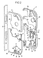
- a door lock 1 according to the invention, as shown in Figures 1 to 3, comprises a box 2 made with two flanges 3 assembled to each other.
- each flange 3 is decomposed, on the one hand, into a top cover 3a, and secondly, a lower cover 3b hardness strengthened.
- Each of the upper covers 3a is made using a sheet metal stamped metal, and each of the lower hardened reinforced bonnet 3b is made of cast steel.
- each lower cover 3b with increased hardness has a thickness greater than that of the upper cover 3a associated.
- each of the two lower covers 3b is extended towards the high by a leg 4 of reduced thickness, intended to be covered by the upper cover 3a associated, and used for fixing said upper cover 3a associated.
- one of the two legs 4 is extended by a pin 5 adapted to come and stay in a mortise 6 presented by the other leg 4.
- each of the two legs 4 carries a perforation 7 in which can be inserted a fixing screw 8 to connect the two legs 4 to each other.
- the thickness of each leg 4 is chosen substantially equal to the difference in thickness measured between said lower cover 3b and said associated upper cover 3a.
- the chest 2 is attached to a headrest 9, and contains the parts well known to those skilled in the art usually used to ensure the locking and unlocking a locking bolt 10.
- Each lower cover 3b has, in the lower part, a central opening 11 adapted to the section of a barrel 12, the latter having a first part 13 and a second part 14 separated one from the other by a medial blade 15 rotating in rotation.
- Each hood lower 3b also has a clearance 16 under the opening Central 11.
- each lower cover 3b has two recesses 17 arranged on either side of the central opening 11, each recess 17 being hollowed out in the thickness of the lower cover 3b and having a bottom 18 traversed by an orifice 19.
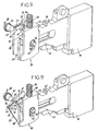
- the bit 15 is housed in said case 2, and the first part 13 and the second portion 14 of the barrel 12 protrude respectively on one side and the other of the said safe 2.
- the first part 13 is intended to protrude outside the premises to be protected (not shown), and that the second portion 14 is intended to protrude from inside the premises to be protected.
- the bit 15 is intended to cooperate with a groove 20 when it is rotated with a key 21 introduced in the barrel 12.
- a cuirass 22 is made of a material at the hardness higher than that of the material in which the barrel 12 is shaped, and has a front face 24 intended to be oriented towards the outside, a side wall 25 designed to cover the first portion 13 of the barrel 12, and a rear face 26 intended to come into contact with the lower cover 3b located at outside the premises to be protected.
- each of these two lugs 27 is traversed by a bore axial threaded.
- the rear face 26 is provided with a nose 30 whose length is substantially equal to the thickness of the trunk 2. This nose 30 is also traversed by a tapped axial bore 31.
- each of the two pins 27 is housed in the recess 17 corresponding to the lower cover 3b located opposite the armor 15, and the nose 30 passes through the clearance 16 provided under the opening central 11 of the trunk 2. In doing so, each lug 27 abuts against the bottom 18 of the recess 17, and the axial bore 29 of each lug 27 is arranged opposite the orifice 19 presented by said corresponding bottom 18.
- a blocking element 32 is then reported around the second part 14 of the cylinder 12.
- This locking element 32 is produced under the form of a washer having a central opening 33 adapted to the section barrel 12, two lateral orifices 34 arranged on either side of the central opening 33, and an orifice 35 located below said opening 33.
- Each of the two orifices 34 is placed in the alignment of a on the other hand, openings 19 presented by the recesses 17, and on the other hand, axial bores 29 presented by the pins 27.
- the orifice 35 is placed in alignment with the axial bore 31 presented by the nose 30.
- a fixing screw 37 provided with a head 38 can then be inserted in each of the orifices 34, 35. As can be deduced from the 3, these fixing screws 37 are respectively screwed into the bores axial 29 of the lugs 27 and in the axial bore 31 of the nose 30, and allow finally to press the locking element 32 against the lower cover 3b which face him.
- a protection device is therefore particularly advantageous since, in addition to the fact that the pins 27 are located outside the trunk 2 and are therefore not likely to interfere with the deflection of the bit 15, the fixing screws 37 which ensure the attachment of the armor 22 to the locking element 32 are not directly accessible from the outside. Indeed, these fixing screws 37 do not can be damaged only to the extent that the burglar has previously destroyed the pins 27 which are masked by the 17. In addition, even in this case, the armor 22 remains solidary of the locking element 32 via the nose 30 which extends under the chest 2. Finally, the armor 22 is protected against attempts of tearing downwardly and upwardly, respectively, to the lugs 27 held blocked in the recesses 17, and the nose 30 housed in the clearance 16.
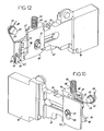
- a recess is dug in the lower part of the cuirass 22 in the vicinity of its rear face 26, and this recess is filled by means of a material 39 with higher hardness that of the material used to shape the cuirass 22.
- this groove 20 is constituted by a plate having an inner face 40 arranged on one side of the tail 41 of the bolt 10.
- This groove 20 has an oblong slot 42 crossed by a transverse axis 43 integral with the trunk 2.
- the groove 20 comprises, on the one hand, a shoulder 44 protruding into which is hollowed a recess 45 in order to constitute a housing adapted to cooperate with the teeth 46 of the tail 41 of the 10, and on the other hand, a stop element 47, separated from the shoulder 44, and having a substantially planar contact surface 48.
- This shoulder 44 is surmounted by a pin 49 on which is centered a first end a compression spring 50.
- the compression spring 50 is housed in a recess 51 a first projecting element 52 formed in the lower cover 3b located face at the groove 20, and has a second end bearing against a stop 53 horizontal overhanging the recess 51.
- a second element in projection 54 is formed above the first, and these two protruding elements 52, 54 allow to sandwich a third element 55 making projection of the other lower cover 3b. It is therefore almost impossible to access to the compression spring 50 during an attempted break-in.
- the inner face of the lower cover 3b located next to the groove 20 is equipped with two longitudinal ribs 56 preventing any lateral displacement of said throat 20.
- a protection plate 57 provided with an internal face 58 is reported on the other side of the tail 41 of the bolt 10.
- This protection plate 57 has an oblong slot 59 traversed by the integral transverse axis 43 2.
- the plate of protection 57 has a protuberance 60 comprising a tooth 61 extended by a lug 62.
- a groove 64 parallel to the tail 41 of the bolt 10 is dug at the top of the protuberance 60 and constitutes a housing apt to accommodate a first branch 65 of a torsion spring 66 placed around a fixed element 67 integral with the door lock 1.
- the second branch 68 of this torsion spring 66 is provided for abut against the return 69 of one of the two lower covers 4.
- This fixed element 67 overhangs the groove 20 and the protective plate 57, and is offset with respect to these.
- the groove 20 and the protection plate 57 are returned, respectively by the compression spring 50 and the torsion spring 66, towards the tail 41 of the bolt 10.
- one of the teeth 46 of the lug 41 of bolt 10 is housed in the recess 45 presented by the shoulder 44 of the groove 20 so as to lock the bolt 10 in translation, the tooth 61 of the protuberance 60 rests on the shank 41 of the bolt 10, and the lug 62 protrusion 60 is inserted between the shoulder 44 and the stop member 47 arranged in the groove 20. More specifically, the lug 62 is intended to come resting against the substantially flat contact surface 48 of the element of stop 47.
- the teeth 46 of the tail 41 of the bolt 10 are disengaged from the groove 20, and the bolt of condemnation 10 can then be driven in translation by said blade 15 during the second half of his race.
- the groove 20 and the protective plate 57 are then animated by a translation movement downwards under the effect of the compression spring 50 and the torsion spring 66 which gradually relax.
- one of the teeth 46 of the tail 41 of the bolt 10 is housed in the recess 45 of the groove 20, and it follows that the bolt 10 is locked in translation.
- the groove 20 and the protective plate 57 remain immobile relative to each other, and therefore the lug 62 remains in bearing against the contact surface 48 of the abutment element 47.
Landscapes
- Engineering & Computer Science (AREA)
- Mechanical Engineering (AREA)
- Lock And Its Accessories (AREA)
- Aiming, Guidance, Guns With A Light Source, Armor, Camouflage, And Targets (AREA)
Applications Claiming Priority (2)
| Application Number | Priority Date | Filing Date | Title |
|---|---|---|---|
| FR0401117A FR2866046B1 (fr) | 2004-02-05 | 2004-02-05 | Serrure de porte munie d'un coffre renforce |
| FR0401117 | 2004-02-05 |
Publications (2)
| Publication Number | Publication Date |
|---|---|
| EP1580355A1 true EP1580355A1 (de) | 2005-09-28 |
| EP1580355B1 EP1580355B1 (de) | 2006-08-23 |
Family
ID=34778539
Family Applications (1)
| Application Number | Title | Priority Date | Filing Date |
|---|---|---|---|
| EP20050002127 Expired - Lifetime EP1580355B1 (de) | 2004-02-05 | 2005-02-02 | Türschloss mit einem verstärkten Element |
Country Status (3)
| Country | Link |
|---|---|
| EP (1) | EP1580355B1 (de) |
| DE (1) | DE602005000082D1 (de) |
| FR (1) | FR2866046B1 (de) |
Cited By (1)
| Publication number | Priority date | Publication date | Assignee | Title |
|---|---|---|---|---|
| DE102011050534A1 (de) * | 2011-05-20 | 2012-11-22 | Sebastian Callens | Einsteckschloss mit einer universellen Adapterplattenvorrichtung zur Ankopplung von im Türblatt eingelassenen Türdrückern oder Türknäufen |
Families Citing this family (1)
| Publication number | Priority date | Publication date | Assignee | Title |
|---|---|---|---|---|
| FR2963634B1 (fr) * | 2010-08-06 | 2012-09-07 | Bricard | Serrure de porte comprenant un dispositif de protection de gorge |
Citations (6)
| Publication number | Priority date | Publication date | Assignee | Title |
|---|---|---|---|---|
| DE7004312U (de) * | 1970-02-07 | 1970-05-21 | Tiefenthal Geb | Schloss, insbesondere tuerschloss. |
| DE1703058A1 (de) * | 1968-03-27 | 1972-04-13 | Hans Bruegemann | Schloss mit Zuhaltungsschiebern |
| GB1548298A (en) * | 1975-04-30 | 1979-07-11 | Gkn Stenman Ab | Locks and to a method of protecting lock mechanism |
| DE3030393A1 (de) * | 1980-08-12 | 1982-02-18 | Fa. Wilhelm Karrenberg, 5620 Velbert | Einsteckschloss |
| DE3111247A1 (de) * | 1981-03-21 | 1982-10-21 | Fa. Wilhelm Karrenberg, 5620 Velbert | Einsteckschloss |
| FR2761395A1 (fr) * | 1997-04-01 | 1998-10-02 | Vachette Sa | Serrure ayant une resistance amelioree a l'effraction |
-
2004
- 2004-02-05 FR FR0401117A patent/FR2866046B1/fr not_active Expired - Fee Related
-
2005
- 2005-02-02 EP EP20050002127 patent/EP1580355B1/de not_active Expired - Lifetime
- 2005-02-02 DE DE200560000082 patent/DE602005000082D1/de not_active Expired - Lifetime
Patent Citations (6)
| Publication number | Priority date | Publication date | Assignee | Title |
|---|---|---|---|---|
| DE1703058A1 (de) * | 1968-03-27 | 1972-04-13 | Hans Bruegemann | Schloss mit Zuhaltungsschiebern |
| DE7004312U (de) * | 1970-02-07 | 1970-05-21 | Tiefenthal Geb | Schloss, insbesondere tuerschloss. |
| GB1548298A (en) * | 1975-04-30 | 1979-07-11 | Gkn Stenman Ab | Locks and to a method of protecting lock mechanism |
| DE3030393A1 (de) * | 1980-08-12 | 1982-02-18 | Fa. Wilhelm Karrenberg, 5620 Velbert | Einsteckschloss |
| DE3111247A1 (de) * | 1981-03-21 | 1982-10-21 | Fa. Wilhelm Karrenberg, 5620 Velbert | Einsteckschloss |
| FR2761395A1 (fr) * | 1997-04-01 | 1998-10-02 | Vachette Sa | Serrure ayant une resistance amelioree a l'effraction |
Cited By (1)
| Publication number | Priority date | Publication date | Assignee | Title |
|---|---|---|---|---|
| DE102011050534A1 (de) * | 2011-05-20 | 2012-11-22 | Sebastian Callens | Einsteckschloss mit einer universellen Adapterplattenvorrichtung zur Ankopplung von im Türblatt eingelassenen Türdrückern oder Türknäufen |
Also Published As
| Publication number | Publication date |
|---|---|
| DE602005000082D1 (de) | 2006-10-05 |
| FR2866046B1 (fr) | 2006-05-26 |
| FR2866046A1 (fr) | 2005-08-12 |
| EP1580355B1 (de) | 2006-08-23 |
Similar Documents
| Publication | Publication Date | Title |
|---|---|---|
| EP1593780A1 (de) | Verriegelungsvorrichtung für Schachtrahmen | |
| CA2337276C (fr) | Dispositif d'obturation a verrouillage selectif | |
| FR2708025A1 (fr) | Dispositif de protection de barillet de serrure de porte. | |
| EP1580355B1 (de) | Türschloss mit einem verstärkten Element | |
| FR2471469A1 (fr) | Butee pour porte pivotante | |
| EP1561885B1 (de) | Schutzvorrichtung für Zuhaltungen eines Türschlo es | |
| EP2063053B1 (de) | Treibstangenverschluss oder Treibstangenschloss | |
| EP1308585B1 (de) | Schloss mit Sicherheitsblock gegen Einbruch | |
| CA2914127C (fr) | Dispositif d'accouplement de deux demi-cylindres | |
| EP1580356B1 (de) | Vorrichtung zum Schutz eines Türschliesszylinders | |
| EP0411969B1 (de) | Türschutzeinrichtung | |
| EP0246989A1 (de) | Sicherheitstür, insbesondere für Kästen, Fächer und Geldschränke | |
| FR2711713A1 (fr) | Dispositif de protection de serrure de porte et porte équipée d'un tel dispositif. | |
| FR2888602A1 (fr) | Serrure de porte | |
| EP0252781A2 (de) | Einstellbares Schliessblech und einbruchsichere Montagevorrichtung | |
| FR2811696A1 (fr) | Ferrure de verrouillage d'ouvrant a mors d'appui interieur manoeuvrable en translation, procede de montage et ouvrant equipe d'une telle ferrure | |
| FR2583452A1 (fr) | Boitier de cremone a plaquer avec condamnation. | |
| BE1014947A3 (fr) | Ferrure de verrouillage d'ouvrant coulissant a boitier technique et parement distincts, procede de montage et ouvrant equipe d'une telle ferrure. | |
| FR3034124A1 (fr) | Dispositif antieffraction d'un rangement | |
| BE1007309A3 (fr) | Serrure de securite. | |
| EP3708747B1 (de) | Notschloss, das von innen entriegelt werden kann | |
| FR2588033A1 (fr) | Serrure a barillet a securite renforcee contre le crochetage | |
| EP0147448A1 (de) | Sicherheitstüreinheit. | |
| FR2963634A1 (fr) | Serrure de porte comprenant un dispositif de protection de gorge | |
| EP1359271A1 (de) | Mechanisches Kastenverriegelungsvorrichtung |
Legal Events
| Date | Code | Title | Description |
|---|---|---|---|
| PUAI | Public reference made under article 153(3) epc to a published international application that has entered the european phase |
Free format text: ORIGINAL CODE: 0009012 |
|
| AK | Designated contracting states |
Kind code of ref document: A1 Designated state(s): AT BE BG CH CY CZ DE DK EE ES FI FR GB GR HU IE IS IT LI LT LU MC NL PL PT RO SE SI SK TR |
|
| AX | Request for extension of the european patent |
Extension state: AL BA HR LV MK YU |
|
| 17P | Request for examination filed |
Effective date: 20050827 |
|
| GRAP | Despatch of communication of intention to grant a patent |
Free format text: ORIGINAL CODE: EPIDOSNIGR1 |
|
| AKX | Designation fees paid |
Designated state(s): DE ES FR GB IT |
|
| GRAS | Grant fee paid |
Free format text: ORIGINAL CODE: EPIDOSNIGR3 |
|
| GRAA | (expected) grant |
Free format text: ORIGINAL CODE: 0009210 |
|
| AK | Designated contracting states |
Kind code of ref document: B1 Designated state(s): DE ES FR GB IT |
|
| PG25 | Lapsed in a contracting state [announced via postgrant information from national office to epo] |
Ref country code: IT Free format text: LAPSE BECAUSE OF FAILURE TO SUBMIT A TRANSLATION OF THE DESCRIPTION OR TO PAY THE FEE WITHIN THE PRESCRIBED TIME-LIMIT;WARNING: LAPSES OF ITALIAN PATENTS WITH EFFECTIVE DATE BEFORE 2007 MAY HAVE OCCURRED AT ANY TIME BEFORE 2007. THE CORRECT EFFECTIVE DATE MAY BE DIFFERENT FROM THE ONE RECORDED. Effective date: 20060823 Ref country code: GB Free format text: LAPSE BECAUSE OF FAILURE TO SUBMIT A TRANSLATION OF THE DESCRIPTION OR TO PAY THE FEE WITHIN THE PRESCRIBED TIME-LIMIT Effective date: 20060823 |
|
| REG | Reference to a national code |
Ref country code: GB Ref legal event code: FG4D Free format text: NOT ENGLISH |
|
| REF | Corresponds to: |
Ref document number: 602005000082 Country of ref document: DE Date of ref document: 20061005 Kind code of ref document: P |
|
| PG25 | Lapsed in a contracting state [announced via postgrant information from national office to epo] |
Ref country code: DE Free format text: LAPSE BECAUSE OF FAILURE TO SUBMIT A TRANSLATION OF THE DESCRIPTION OR TO PAY THE FEE WITHIN THE PRESCRIBED TIME-LIMIT Effective date: 20061124 |
|
| PG25 | Lapsed in a contracting state [announced via postgrant information from national office to epo] |
Ref country code: ES Free format text: LAPSE BECAUSE OF FAILURE TO SUBMIT A TRANSLATION OF THE DESCRIPTION OR TO PAY THE FEE WITHIN THE PRESCRIBED TIME-LIMIT Effective date: 20061204 |
|
| GBV | Gb: ep patent (uk) treated as always having been void in accordance with gb section 77(7)/1977 [no translation filed] |
Effective date: 20060823 |
|
| PLBE | No opposition filed within time limit |
Free format text: ORIGINAL CODE: 0009261 |
|
| STAA | Information on the status of an ep patent application or granted ep patent |
Free format text: STATUS: NO OPPOSITION FILED WITHIN TIME LIMIT |
|
| 26N | No opposition filed |
Effective date: 20070524 |
|
| REG | Reference to a national code |
Ref country code: FR Ref legal event code: PLFP Year of fee payment: 12 |
|
| REG | Reference to a national code |
Ref country code: FR Ref legal event code: PLFP Year of fee payment: 13 |
|
| REG | Reference to a national code |
Ref country code: FR Ref legal event code: PLFP Year of fee payment: 14 |
|
| PGFP | Annual fee paid to national office [announced via postgrant information from national office to epo] |
Ref country code: FR Payment date: 20240117 Year of fee payment: 20 |