EP1580356B1 - Vorrichtung zum Schutz eines Türschliesszylinders - Google Patents
Vorrichtung zum Schutz eines Türschliesszylinders Download PDFInfo
- Publication number
- EP1580356B1 EP1580356B1 EP20050002128 EP05002128A EP1580356B1 EP 1580356 B1 EP1580356 B1 EP 1580356B1 EP 20050002128 EP20050002128 EP 20050002128 EP 05002128 A EP05002128 A EP 05002128A EP 1580356 B1 EP1580356 B1 EP 1580356B1
- Authority
- EP
- European Patent Office
- Prior art keywords
- case
- protection device
- shell
- cylinder
- rear face
- Prior art date
- Legal status (The legal status is an assumption and is not a legal conclusion. Google has not performed a legal analysis and makes no representation as to the accuracy of the status listed.)
- Expired - Lifetime
Links
- 230000000903 blocking effect Effects 0.000 claims description 5
- 230000001747 exhibiting effect Effects 0.000 claims 1
- 230000001681 protective effect Effects 0.000 description 3
- 241001441732 Ostraciidae Species 0.000 description 1
- 230000003111 delayed effect Effects 0.000 description 1
- 230000000694 effects Effects 0.000 description 1
- 210000001835 viscera Anatomy 0.000 description 1
Images

Classifications
-
- E—FIXED CONSTRUCTIONS
- E05—LOCKS; KEYS; WINDOW OR DOOR FITTINGS; SAFES
- E05B—LOCKS; ACCESSORIES THEREFOR; HANDCUFFS
- E05B9/00—Lock casings or latch-mechanism casings ; Fastening locks or fasteners or parts thereof to the wing
- E05B9/08—Fastening locks or fasteners or parts thereof, e.g. the casings of latch-bolt locks or cylinder locks to the wing
- E05B9/084—Fastening of lock cylinders, plugs or cores
-
- E—FIXED CONSTRUCTIONS
- E05—LOCKS; KEYS; WINDOW OR DOOR FITTINGS; SAFES
- E05B—LOCKS; ACCESSORIES THEREFOR; HANDCUFFS
- E05B15/00—Other details of locks; Parts for engagement by bolts of fastening devices
- E05B15/02—Striking-plates; Keepers; Bolt staples; Escutcheons
-
- E—FIXED CONSTRUCTIONS
- E05—LOCKS; KEYS; WINDOW OR DOOR FITTINGS; SAFES
- E05B—LOCKS; ACCESSORIES THEREFOR; HANDCUFFS
- E05B17/00—Accessories in connection with locks
- E05B17/20—Means independent of the locking mechanism for preventing unauthorised opening, e.g. for securing the bolt in the fastening position
Definitions
- the present invention relates, on the one hand, to a protection device for a door lock comprising a barrel provided with a bit arranged to be positioned inside a box, and on the other hand, to a door lock equipped with such a protective device.
- the fixing screws are not accessible from outside the room, the burglar can access the barrel by fracturing the shield.
- a protection device has disadvantages residing in the fact that, on the one hand, the box must have an internal volume sufficient to allow the housing of the pads, and secondly, the cylindrical surfaces of the parallel faces of the pads. are relatively delicate to achieve.
- the object of the present invention is to remedy the drawbacks mentioned above, and for this purpose consists in a protective device for a door lock comprising a barrel provided with a bit arranged to be positioned inside a trunk, said protection device comprising a cuirass adapted to cover a first portion of the barrel opening out of the room to be protected, a locking element adapted to grip a second portion of the barrel opening inside the room to be protected, and fastening means provided to pass through the trunk and allow the attachment of the armor to the locking element, said armor being intended to come into contact with the side of the box located outside the room to be protected by means of a rear face equipped with at least two lugs located in the extension of the armor and each traversed by an axial bore, characterized in that each of these lugs is adapted to be housed in a corresponding recess dug in the thickness of the trunk face located opposite the rear face. of the cuirass.
- these lugs being designed so as not to enter the trunk, and therefore to remain outside the trunk, it follows, on the one hand, that it is no longer necessary to provide a clearance to the trunk. inside the trunk, and secondly, that these lugs can no longer impede the movement of the blade. These lugs are therefore small and can be shaped very easily, which also reduces the total weight and the cost of the armor.
- each recess comprises a bottom through which an orifice is provided to be located facing the axial bore presented by the corresponding pin.
- the rear face is provided with a nose designed to extend under the trunk.
- This nose preferably has a length substantially equal to the thickness of the trunk, and is provided with an axial bore.
- the chest has a clearance for the passage of the nose.
- a recess is dug in the lower part of the armor in the vicinity of its rear face, and this recess is filled by means of a material of higher hardness. It will be very difficult for the burglar to pierce the cuirass in lower part in order to reach the fastening means passing through the axial bores of the lugs.
- the blocking element is advantageously designed as a washer having, on the one hand, a central perforation adapted to the barrel section, and, on the other hand, orifices provided for the passage of the means of rotation. fixation.
- the present invention also relates to a door lock comprising a trunk crossed by a barrel provided with a movable rotating blade housed in the trunk, characterized in that it comprises a protection device according to the invention.
- each flange 3 has two recesses 12 disposed on either side of the central opening 6, each recess 12 being hollowed into the thickness of the flange 3 and having a bottom 13 through which a hole 14 passes.
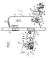
- the blade 10 is housed in said trunk 2, and the first portion 8 and the second portion 9 of the barrel 7 project respectively on one side and the other of said Chest 2.
- the first part 8 is intended to protrude outside the room to be protected (not shown), and that the second part 9 is provided to protrude to the outside. inside the premises to be protected.
- the rear face 18 is provided with a nose 22 whose length is substantially equal to the thickness of the trunk 2. This nose 22 is also traversed by a tapped axial bore 24.
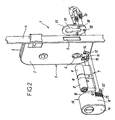
- each of the two lugs 19 is housed in the corresponding recess 12 of the flange 3 located opposite the armor 15, and the nose 22 passes through the clearance 11 provided under the central opening 6 of the trunk 2. In doing so, each lug 19 abuts against the bottom 13 of the recess 12, and the axial bore 21 of each lug 19 is arranged opposite the orifice 14 presented by said corresponding bottom 13.
- a blocking element 25 is then attached around the second part 9 of the cylinder 7.
- This locking element 25 is in the form of a washer having a central opening 27 adapted to the barrel section 7, two lateral orifices 28 arranged on either side of the central opening 27, and an orifice 29 located below said central opening 27.
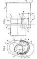
- Each of the two orifices 28 is placed in alignment with, on the one hand, orifices 14 presented by the recesses. 12, and on the other hand, axial bores 21 presented by the lugs 19.
- the orifice 29 is placed in alignment with the axial bore 24 presented by the nose 22.
- a fixing screw 30 provided with a head 31 can then be inserted into each of the orifices 28, 29. As represented in FIG. 4, these fixing screws 30 are respectively screwed into the axial bores 21 of the lugs 19 and into the axial bore 24 of the nose 22, and finally allow to press the locking element 25 against the flange 3 which faces it.
- a protection device is therefore particularly advantageous since, in addition to the fact that the lugs 19 are located outside the trunk 2 and are therefore not likely to interfere with the movement of the blade 10, the fixing screws 30 which ensure the attachment of the armor 15 to the locking element 25 are not directly accessible from the outside. Indeed, these fixing screws 30 can be damaged only to the extent that the burglar has previously destroyed the pins 19 which are hidden by the recesses 12. In addition, even in this case, the armor 15 remains attached to the element 25 by the nose 22 which extends under the chest 2. Finally, the armor 15 is protected against the attempts of tearing downwards and upwards respectively, respectively, with the lugs 19 held blocked in the recesses 12, and nose 22 housed in the clearance 11.
- a recess is dug in the lower part of the armor 15 in the vicinity of its rear face 18, and this recess is filled by means of a material 32 with a higher hardness than the material used to shape the cuirass 15.
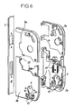
- each flange 3 is advantageously decomposed, on the one hand, into a first element 3a covering the upper part of the trunk 2, and on the other hand, into a second element 3b with reinforced hardness. covering the lower part of the box 2.
- the second element 3b has, at its inner face, protuberances 33 directed towards the inside of the box 2 and provided to frame certain parts of the lock 1 to protect them effectively.
- These parts are the parts traditionally used to allow the translational movement of the locking bolt 5 during the rotation of the key 40, and include in particular the groove (not shown) which cooperates with the tail of the locking bolt 5.
Landscapes
- Engineering & Computer Science (AREA)
- Mechanical Engineering (AREA)
- Lock And Its Accessories (AREA)
Claims (10)
- Vorrichtung zum Schutz eines Türschließzylinders (1) umfassend einen Zylinder (7), der eine für die Abringung im Inneren eines Schlossgehäuses (2) vorgesehene Schließnase (10) aufweist, wobei die genannte Schutzvorrichtung einen Schutzpanzer (15), welcher geeignet ist, einen außerhalb des zu schützenden Raumes mündenden ersten Teil (8) des Zylinders aufzunehmen, ein Blockierelement (25), das geeignet ist, einen im Inneren des zu schützenden Raumes mündenden zweiten Teil (9) des Zylinders zu umschließen, und Befestigungsmittel (30) aufweist, die vorgesehen sind, um das Schlossgehäuse zu durchqueren und die Verbindung des Schutzpanzers mit dem Blockierelement zu ermöglichen, wobei der genannte Schutzpanzer dazu bestimmt ist, über eine mit mindestens zwei in der Verlängerung des Schutzpanzers liegenden und jeweils durch eine Axialbohrung (21) durchquerte Anschläge (19) versehene hintere Fläche (18) mit der außerhalb des zu schützenden Raumes liegenden Fläche des Schlossgehäuses in Kontakt zu kommen, dadurch gekennzeichnet, dass jeder der genannten Anschläge geeignet ist, in einer entsprechenden in der Stärke der gegenüber der hinteren Fläche des Schutzpanzers liegenden Fläche des Schlossgehäuses eingearbeiteten Vertiefung (12) zu liegen zu kommen.
- Schutzvorrichtung nach Anspruch 1, dadurch gekennzeichnet, dass jede Vertiefung (12) einen Boden (13) aufweist, der durch eine Öffnung (4) durchquert wird, die vorgesehen ist, um benachbart der Axialbohrung (21) zu liegen zu kommen, die der entsprechende Anschlag (19) aufweist.
- Schutzvorrichtung nach den Ansprüchen 1 oder 2, dadurch gekennzeichnet, dass die hintere Fläche (18) des Schutzpanzers (15) zwei Anschläge (19) aufweist, die beiderseits einer zentralen, an den Querschnitt des Zylinders (7) angepassten Öffnung (20) angeordnet sind.
- Schutzvorrichtung nach einem der Ansprüche 1 bis 3, dadurch gekennzeichnet, dass im unteren Teil des Schutzpanzers (15) die hintere Fläche (18) mit einer Nase (22) versehen ist, welche so ausgestaltet ist, dass sie sich unterhalb des Schlossgehäuses (2) erstreckt.
- Schutzvorrichtung nach Anspruch 4, dadurch gekennzeichnet, dass die Nase (22) eine im Wesentlichen der Breite des Schlossgehäuses (2) entsprechende Länge besitzt, und dass sie mit einer Axialbohrung (24) versehen ist.
- Schutzvorrichtung nach Anspruch 5, dadurch gekennzeichnet, dass das Schlossgehäuse (2) eine Aussparung (11) für den Durchtritt der Nase (22) aufweist.
- Schutzvorrichtung nach einem der Ansprüche 1 bis 6, dadurch gekennzeichnet, dass im unteren Teil des Schutzpanzers (15) in der Nähe seiner hinteren Fläche (18) eine Auskehlung eingearbeitet ist und dass die genannte Auskehlung mit einem Material (32) mit größerer Härte aufgefüllt ist.
- Schutzvorrichtung nach einem der Ansprüche 1 bis 7, dadurch gekennzeichnet, dass das Blockierelement (25) in Form einer Scheibe ausgeführt ist, die einerseits eine an den Querschnitt des Zylinders (7) angepasste zentrale Bohrung (27) und andererseits Öffnungen (28, 29), die für den Durchtritt der Befestigungsmittel (30) vorgesehen sind, aufweist.
- Türschließzylinder (1), umfassend ein Schlossgehäuse (2), das von einem Zylinder (7) durchquert ist, der eine im Schlossgehäuse liegende drehbare Schließnase (10) aufweist, dadurch gekennzeichnet, dass er eine Schutzvorrichtung nach einem der Ansprüche 1 bis 8 aufweist.
- Türschließzylinder (1) nach Anspruch 9, dadurch gekennzeichnet, dass das Schlossgehäuse (2) durch zwei miteinander verbundene Schilde (3) gebildet ist, und dass jeder Schild jeweils besteht einerseits aus einem den oberen Teil des Schlossgehäuses abdeckenden ersten Element (3a) und andererseits aus einem den unteren Teil des Schlossgehäuses abdeckenden zweiten Element (3b) mit erhöhter Härte.
Applications Claiming Priority (2)
| Application Number | Priority Date | Filing Date | Title |
|---|---|---|---|
| FR0401092 | 2004-02-05 | ||
| FR0401092A FR2866047B1 (fr) | 2004-02-05 | 2004-02-05 | Dispositif de protection de barillet de serrure de porte |
Publications (2)
| Publication Number | Publication Date |
|---|---|
| EP1580356A1 EP1580356A1 (de) | 2005-09-28 |
| EP1580356B1 true EP1580356B1 (de) | 2006-08-23 |
Family
ID=34778524
Family Applications (1)
| Application Number | Title | Priority Date | Filing Date |
|---|---|---|---|
| EP20050002128 Expired - Lifetime EP1580356B1 (de) | 2004-02-05 | 2005-02-02 | Vorrichtung zum Schutz eines Türschliesszylinders |
Country Status (3)
| Country | Link |
|---|---|
| EP (1) | EP1580356B1 (de) |
| DE (1) | DE602005000083D1 (de) |
| FR (1) | FR2866047B1 (de) |
Families Citing this family (4)
| Publication number | Priority date | Publication date | Assignee | Title |
|---|---|---|---|---|
| FR2880644B1 (fr) * | 2005-01-10 | 2008-07-11 | Massimo Valente | Serrure a securite amelioree contre l'effraction |
| GB2512579B (en) * | 2013-03-08 | 2019-12-04 | Uap Ltd | A lock guard |
| IT201900009720A1 (it) * | 2019-06-21 | 2020-12-21 | Fabbro Emanuela Dal | Dispositivo di protezione per serrature. |
| IT201900009732A1 (it) * | 2019-06-21 | 2020-12-21 | Pier Luigi Oliana | Dispositivo di protezione per serrature. |
Family Cites Families (5)
| Publication number | Priority date | Publication date | Assignee | Title |
|---|---|---|---|---|
| DE3604719A1 (de) * | 1986-02-14 | 1987-08-20 | Feral Sicherheitstechnik Elisa | Einbruchsicherung fuer schloesser |
| CH672939A5 (de) * | 1987-03-06 | 1990-01-15 | Ernst Keller | |
| FR2708025B1 (fr) * | 1993-07-22 | 1995-09-15 | Vachette Sa | Dispositif de protection de barillet de serrure de porte. |
| FR2816975B1 (fr) * | 2000-11-20 | 2003-09-26 | Jean Michel Louvet | Dispositif de protection conte l'effraction de serrures a cylindres europeen |
| FR2831911B1 (fr) * | 2001-11-05 | 2004-01-02 | Bricard Sa | Bloc de surete anti effraction pour serrure |
-
2004
- 2004-02-05 FR FR0401092A patent/FR2866047B1/fr not_active Expired - Fee Related
-
2005
- 2005-02-02 EP EP20050002128 patent/EP1580356B1/de not_active Expired - Lifetime
- 2005-02-02 DE DE200560000083 patent/DE602005000083D1/de not_active Expired - Lifetime
Also Published As
| Publication number | Publication date |
|---|---|
| FR2866047B1 (fr) | 2006-05-26 |
| DE602005000083D1 (de) | 2006-10-05 |
| EP1580356A1 (de) | 2005-09-28 |
| FR2866047A1 (fr) | 2005-08-12 |
Similar Documents
| Publication | Publication Date | Title |
|---|---|---|
| EP2611656B1 (de) | Lenkungsverriegelung für ein kraftfahrzeug | |
| EP4176756B1 (de) | Einsatzteil für uhrenarmband | |
| FR2708025A1 (fr) | Dispositif de protection de barillet de serrure de porte. | |
| EP1580356B1 (de) | Vorrichtung zum Schutz eines Türschliesszylinders | |
| EP2123851B1 (de) | Schließmechanismus, der eine Schutzverkleidung umfasst | |
| EP2825423B1 (de) | Sperre mit riegelsicherung für eine kraftfahrzeuglenksäule | |
| EP1308585B1 (de) | Schloss mit Sicherheitsblock gegen Einbruch | |
| FR2564884A1 (fr) | Dispositif de securite pour serrure du genre en applique. | |
| FR2831911A1 (fr) | Bloc de surete anti effraction pour serrure | |
| EP3208409B1 (de) | Einbruchsicherungssystem für garagentor | |
| EP1688565B1 (de) | Schloss mit erhöhter Sicherheit gegen Aufbrechen | |
| EP1580355B1 (de) | Türschloss mit einem verstärkten Element | |
| EP0745745B1 (de) | Schutzvorrichtung für Aufnahmegehäuse eines Verriegelungsbetriebssystems mit Schlüssel | |
| CA2914127C (fr) | Dispositif d'accouplement de deux demi-cylindres | |
| EP2909400B1 (de) | Bolzenbefestigungsvorrichtung für eine kraftfahrzeugtür und kraftfahrzeug mit solch einer befestigungsvorrichtung | |
| FR2699588A1 (fr) | Bloc-porte à montage réversible avec ouverture à droite ou à gauche. | |
| EP0874114A1 (de) | Zylindersicherheitsschloss mit erhöhtem Einbruchswiderstand | |
| EP2586938B1 (de) | Verriegelungsvorrichtung für ein Öffnungselement | |
| FR2613750A1 (fr) | Dispositif de protection anti-percement d'une serrure a barillet | |
| FR2816975A1 (fr) | Dispositif de protection conte l'effraction de serrures a cylindres europeen | |
| FR3034124A1 (fr) | Dispositif antieffraction d'un rangement | |
| FR3071531B1 (fr) | Bouclier de porte blindee pour proteger la serrure de cette porte | |
| EP3581739B1 (de) | Schutzvorrichtung für entriegelungsmechanismus eines türschlosses vom typ mit flächenbündigem griff | |
| FR2477617A1 (fr) | Rosette anti-effraction pour une serrure encastree | |
| EP3708747B1 (de) | Notschloss, das von innen entriegelt werden kann |
Legal Events
| Date | Code | Title | Description |
|---|---|---|---|
| PUAI | Public reference made under article 153(3) epc to a published international application that has entered the european phase |
Free format text: ORIGINAL CODE: 0009012 |
|
| AK | Designated contracting states |
Kind code of ref document: A1 Designated state(s): AT BE BG CH CY CZ DE DK EE ES FI FR GB GR HU IE IS IT LI LT LU MC NL PL PT RO SE SI SK TR |
|
| AX | Request for extension of the european patent |
Extension state: AL BA HR LV MK YU |
|
| 17P | Request for examination filed |
Effective date: 20050827 |
|
| GRAP | Despatch of communication of intention to grant a patent |
Free format text: ORIGINAL CODE: EPIDOSNIGR1 |
|
| AKX | Designation fees paid |
Designated state(s): DE ES FR GB IT |
|
| GRAS | Grant fee paid |
Free format text: ORIGINAL CODE: EPIDOSNIGR3 |
|
| GRAA | (expected) grant |
Free format text: ORIGINAL CODE: 0009210 |
|
| AK | Designated contracting states |
Kind code of ref document: B1 Designated state(s): DE ES FR GB IT |
|
| PG25 | Lapsed in a contracting state [announced via postgrant information from national office to epo] |
Ref country code: IT Free format text: LAPSE BECAUSE OF FAILURE TO SUBMIT A TRANSLATION OF THE DESCRIPTION OR TO PAY THE FEE WITHIN THE PRESCRIBED TIME-LIMIT;WARNING: LAPSES OF ITALIAN PATENTS WITH EFFECTIVE DATE BEFORE 2007 MAY HAVE OCCURRED AT ANY TIME BEFORE 2007. THE CORRECT EFFECTIVE DATE MAY BE DIFFERENT FROM THE ONE RECORDED. Effective date: 20060823 Ref country code: GB Free format text: LAPSE BECAUSE OF FAILURE TO SUBMIT A TRANSLATION OF THE DESCRIPTION OR TO PAY THE FEE WITHIN THE PRESCRIBED TIME-LIMIT Effective date: 20060823 |
|
| REG | Reference to a national code |
Ref country code: GB Ref legal event code: FG4D Free format text: NOT ENGLISH |
|
| REF | Corresponds to: |
Ref document number: 602005000083 Country of ref document: DE Date of ref document: 20061005 Kind code of ref document: P |
|
| PG25 | Lapsed in a contracting state [announced via postgrant information from national office to epo] |
Ref country code: DE Free format text: LAPSE BECAUSE OF FAILURE TO SUBMIT A TRANSLATION OF THE DESCRIPTION OR TO PAY THE FEE WITHIN THE PRESCRIBED TIME-LIMIT Effective date: 20061124 |
|
| PG25 | Lapsed in a contracting state [announced via postgrant information from national office to epo] |
Ref country code: ES Free format text: LAPSE BECAUSE OF FAILURE TO SUBMIT A TRANSLATION OF THE DESCRIPTION OR TO PAY THE FEE WITHIN THE PRESCRIBED TIME-LIMIT Effective date: 20061204 |
|
| GBV | Gb: ep patent (uk) treated as always having been void in accordance with gb section 77(7)/1977 [no translation filed] |
Effective date: 20060823 |
|
| PLBE | No opposition filed within time limit |
Free format text: ORIGINAL CODE: 0009261 |
|
| STAA | Information on the status of an ep patent application or granted ep patent |
Free format text: STATUS: NO OPPOSITION FILED WITHIN TIME LIMIT |
|
| 26N | No opposition filed |
Effective date: 20070524 |
|
| REG | Reference to a national code |
Ref country code: FR Ref legal event code: PLFP Year of fee payment: 12 |
|
| REG | Reference to a national code |
Ref country code: FR Ref legal event code: PLFP Year of fee payment: 13 |
|
| REG | Reference to a national code |
Ref country code: FR Ref legal event code: PLFP Year of fee payment: 14 |
|
| PGFP | Annual fee paid to national office [announced via postgrant information from national office to epo] |
Ref country code: FR Payment date: 20240117 Year of fee payment: 20 |