EP1580355A1 - Door lock with a reinforced case - Google Patents
Door lock with a reinforced case Download PDFInfo
- Publication number
- EP1580355A1 EP1580355A1 EP05002127A EP05002127A EP1580355A1 EP 1580355 A1 EP1580355 A1 EP 1580355A1 EP 05002127 A EP05002127 A EP 05002127A EP 05002127 A EP05002127 A EP 05002127A EP 1580355 A1 EP1580355 A1 EP 1580355A1
- Authority
- EP
- European Patent Office
- Prior art keywords
- door lock
- groove
- cover
- hardness
- reinforced
- Prior art date
- Legal status (The legal status is an assumption and is not a legal conclusion. Google has not performed a legal analysis and makes no representation as to the accuracy of the status listed.)
- Granted
Links
Images


Classifications
-
- E—FIXED CONSTRUCTIONS
- E05—LOCKS; KEYS; WINDOW OR DOOR FITTINGS; SAFES
- E05B—LOCKS; ACCESSORIES THEREFOR; HANDCUFFS
- E05B9/00—Lock casings or latch-mechanism casings ; Fastening locks or fasteners or parts thereof to the wing
- E05B9/02—Casings of latch-bolt or deadbolt locks
-
- E—FIXED CONSTRUCTIONS
- E05—LOCKS; KEYS; WINDOW OR DOOR FITTINGS; SAFES
- E05B—LOCKS; ACCESSORIES THEREFOR; HANDCUFFS
- E05B17/00—Accessories in connection with locks
- E05B17/20—Means independent of the locking mechanism for preventing unauthorised opening, e.g. for securing the bolt in the fastening position
- E05B17/2084—Means to prevent forced opening by attack, tampering or jimmying
-
- E—FIXED CONSTRUCTIONS
- E05—LOCKS; KEYS; WINDOW OR DOOR FITTINGS; SAFES
- E05B—LOCKS; ACCESSORIES THEREFOR; HANDCUFFS
- E05B9/00—Lock casings or latch-mechanism casings ; Fastening locks or fasteners or parts thereof to the wing
- E05B9/08—Fastening locks or fasteners or parts thereof, e.g. the casings of latch-bolt locks or cylinder locks to the wing
- E05B9/084—Fastening of lock cylinders, plugs or cores
-
- E—FIXED CONSTRUCTIONS
- E05—LOCKS; KEYS; WINDOW OR DOOR FITTINGS; SAFES
- E05B—LOCKS; ACCESSORIES THEREFOR; HANDCUFFS
- E05B63/00—Locks or fastenings with special structural characteristics
- E05B63/0017—Locks with sliding bolt without provision for latching
Definitions
- the present invention relates to a door lock having a trunk crossed by a barrel provided with a rotating bit provided to push back a suitable groove, under the action of an elastic return means, to come into engagement with teeth presented by a tail of a bolt of conviction.
- Another solution consists in fixing plates of protection on both sides of the door to be protected, substantially at the level of the lock.
- the disadvantage is that these plates being immediately accessible to the burglar, the protection conferred by them is relatively minimal.
- the present invention aims to overcome the disadvantages previously mentioned, and consists of a door lock comprising a trunk crossed by a barrel equipped with a rotary bit provided for push a suitable groove, under the action of an elastic return means, to come into engagement with teeth presented by a tail of a bolt of condemnation, characterized in that the trunk is made using two complementary flasks each comprising at least one hardness zone reinforced located respectively opposite the groove and facing the tail of the bolt.
- each flange comprises two separate covers, one of which is made of a material with increased hardness.
- each bonnet with reinforced hardness is made of cast steel, and each associated cover is made using a sheet metal stamped metal.
- each reinforced hardness hood has a greater thickness than the associated cover.
- each bonnet with reinforced hardness is extended by at least one lug of reduced thickness for fixing the associated hood.
- the thickness of each leg is chosen substantially equal to the difference in thickness measured between hardened bonnet and associated hood.
- each bonnet with reinforced hardness has an internal face equipped with at least one protuberance adapted to protect the throat.
- the groove may have a protruding element overhanging the groove.
- the latter is preferably surmounted by a nipple on which is the elastic return means, and the projecting element has advantageously a recess serving as a housing for the return means elastic.
- the inner face of the reinforced hardness hood facing the throat can be equipped with two longitudinal ribs framing the throat.
- a lock according to the invention can include a breastplate intended to cover a first part of the barrel opening out of the room to be protected, a blocking element suitable for enclose a second part of the barrel opening inside the room to protect, and fastening means provided to cross the trunk and allow the attachment of the armor to the locking element, said armor being intended to come into contact with the flange located outside the room to be protected by via a rear face equipped with at least two lugs located in the extension of the cuirass and each traversed by an axial bore, and each of these pins being adapted to be housed in a recess corresponding dug in the thickness of the flange located opposite the face back of the cuirass.
- the fastening means not being accessible since outside the premises, the burglar can only access the barrel after having fractured the cuirass.
- each recess comprises a bottom crossed by an orifice intended to be located opposite the axial bore presented by the corresponding ergot.
- the rear face is preferably provided with a nose designed to extend under the chest.
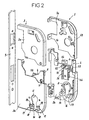
- a door lock 1 according to the invention, as shown in Figures 1 to 3, comprises a box 2 made with two flanges 3 assembled to each other.
- each flange 3 is decomposed, on the one hand, into a top cover 3a, and secondly, a lower cover 3b hardness strengthened.
- Each of the upper covers 3a is made using a sheet metal stamped metal, and each of the lower hardened reinforced bonnet 3b is made of cast steel.
- each lower cover 3b with increased hardness has a thickness greater than that of the upper cover 3a associated.
- each of the two lower covers 3b is extended towards the high by a leg 4 of reduced thickness, intended to be covered by the upper cover 3a associated, and used for fixing said upper cover 3a associated.
- one of the two legs 4 is extended by a pin 5 adapted to come and stay in a mortise 6 presented by the other leg 4.
- each of the two legs 4 carries a perforation 7 in which can be inserted a fixing screw 8 to connect the two legs 4 to each other.
- the thickness of each leg 4 is chosen substantially equal to the difference in thickness measured between said lower cover 3b and said associated upper cover 3a.
- the chest 2 is attached to a headrest 9, and contains the parts well known to those skilled in the art usually used to ensure the locking and unlocking a locking bolt 10.
- Each lower cover 3b has, in the lower part, a central opening 11 adapted to the section of a barrel 12, the latter having a first part 13 and a second part 14 separated one from the other by a medial blade 15 rotating in rotation.
- Each hood lower 3b also has a clearance 16 under the opening Central 11.
- each lower cover 3b has two recesses 17 arranged on either side of the central opening 11, each recess 17 being hollowed out in the thickness of the lower cover 3b and having a bottom 18 traversed by an orifice 19.
- the bit 15 is housed in said case 2, and the first part 13 and the second portion 14 of the barrel 12 protrude respectively on one side and the other of the said safe 2.
- the first part 13 is intended to protrude outside the premises to be protected (not shown), and that the second portion 14 is intended to protrude from inside the premises to be protected.
- the bit 15 is intended to cooperate with a groove 20 when it is rotated with a key 21 introduced in the barrel 12.
- a cuirass 22 is made of a material at the hardness higher than that of the material in which the barrel 12 is shaped, and has a front face 24 intended to be oriented towards the outside, a side wall 25 designed to cover the first portion 13 of the barrel 12, and a rear face 26 intended to come into contact with the lower cover 3b located at outside the premises to be protected.
- each of these two lugs 27 is traversed by a bore axial threaded.
- the rear face 26 is provided with a nose 30 whose length is substantially equal to the thickness of the trunk 2. This nose 30 is also traversed by a tapped axial bore 31.
- each of the two pins 27 is housed in the recess 17 corresponding to the lower cover 3b located opposite the armor 15, and the nose 30 passes through the clearance 16 provided under the opening central 11 of the trunk 2. In doing so, each lug 27 abuts against the bottom 18 of the recess 17, and the axial bore 29 of each lug 27 is arranged opposite the orifice 19 presented by said corresponding bottom 18.
- a blocking element 32 is then reported around the second part 14 of the cylinder 12.
- This locking element 32 is produced under the form of a washer having a central opening 33 adapted to the section barrel 12, two lateral orifices 34 arranged on either side of the central opening 33, and an orifice 35 located below said opening 33.
- Each of the two orifices 34 is placed in the alignment of a on the other hand, openings 19 presented by the recesses 17, and on the other hand, axial bores 29 presented by the pins 27.
- the orifice 35 is placed in alignment with the axial bore 31 presented by the nose 30.
- a fixing screw 37 provided with a head 38 can then be inserted in each of the orifices 34, 35. As can be deduced from the 3, these fixing screws 37 are respectively screwed into the bores axial 29 of the lugs 27 and in the axial bore 31 of the nose 30, and allow finally to press the locking element 32 against the lower cover 3b which face him.
- a protection device is therefore particularly advantageous since, in addition to the fact that the pins 27 are located outside the trunk 2 and are therefore not likely to interfere with the deflection of the bit 15, the fixing screws 37 which ensure the attachment of the armor 22 to the locking element 32 are not directly accessible from the outside. Indeed, these fixing screws 37 do not can be damaged only to the extent that the burglar has previously destroyed the pins 27 which are masked by the 17. In addition, even in this case, the armor 22 remains solidary of the locking element 32 via the nose 30 which extends under the chest 2. Finally, the armor 22 is protected against attempts of tearing downwardly and upwardly, respectively, to the lugs 27 held blocked in the recesses 17, and the nose 30 housed in the clearance 16.
- a recess is dug in the lower part of the cuirass 22 in the vicinity of its rear face 26, and this recess is filled by means of a material 39 with higher hardness that of the material used to shape the cuirass 22.
- this groove 20 is constituted by a plate having an inner face 40 arranged on one side of the tail 41 of the bolt 10.
- This groove 20 has an oblong slot 42 crossed by a transverse axis 43 integral with the trunk 2.
- the groove 20 comprises, on the one hand, a shoulder 44 protruding into which is hollowed a recess 45 in order to constitute a housing adapted to cooperate with the teeth 46 of the tail 41 of the 10, and on the other hand, a stop element 47, separated from the shoulder 44, and having a substantially planar contact surface 48.
- This shoulder 44 is surmounted by a pin 49 on which is centered a first end a compression spring 50.
- the compression spring 50 is housed in a recess 51 a first projecting element 52 formed in the lower cover 3b located face at the groove 20, and has a second end bearing against a stop 53 horizontal overhanging the recess 51.
- a second element in projection 54 is formed above the first, and these two protruding elements 52, 54 allow to sandwich a third element 55 making projection of the other lower cover 3b. It is therefore almost impossible to access to the compression spring 50 during an attempted break-in.
- the inner face of the lower cover 3b located next to the groove 20 is equipped with two longitudinal ribs 56 preventing any lateral displacement of said throat 20.
- a protection plate 57 provided with an internal face 58 is reported on the other side of the tail 41 of the bolt 10.
- This protection plate 57 has an oblong slot 59 traversed by the integral transverse axis 43 2.
- the plate of protection 57 has a protuberance 60 comprising a tooth 61 extended by a lug 62.
- a groove 64 parallel to the tail 41 of the bolt 10 is dug at the top of the protuberance 60 and constitutes a housing apt to accommodate a first branch 65 of a torsion spring 66 placed around a fixed element 67 integral with the door lock 1.
- the second branch 68 of this torsion spring 66 is provided for abut against the return 69 of one of the two lower covers 4.
- This fixed element 67 overhangs the groove 20 and the protective plate 57, and is offset with respect to these.
- the groove 20 and the protection plate 57 are returned, respectively by the compression spring 50 and the torsion spring 66, towards the tail 41 of the bolt 10.
- one of the teeth 46 of the lug 41 of bolt 10 is housed in the recess 45 presented by the shoulder 44 of the groove 20 so as to lock the bolt 10 in translation, the tooth 61 of the protuberance 60 rests on the shank 41 of the bolt 10, and the lug 62 protrusion 60 is inserted between the shoulder 44 and the stop member 47 arranged in the groove 20. More specifically, the lug 62 is intended to come resting against the substantially flat contact surface 48 of the element of stop 47.
- the teeth 46 of the tail 41 of the bolt 10 are disengaged from the groove 20, and the bolt of condemnation 10 can then be driven in translation by said blade 15 during the second half of his race.
- the groove 20 and the protective plate 57 are then animated by a translation movement downwards under the effect of the compression spring 50 and the torsion spring 66 which gradually relax.
- one of the teeth 46 of the tail 41 of the bolt 10 is housed in the recess 45 of the groove 20, and it follows that the bolt 10 is locked in translation.
- the groove 20 and the protective plate 57 remain immobile relative to each other, and therefore the lug 62 remains in bearing against the contact surface 48 of the abutment element 47.
Abstract
Description
La présente invention se rapporte à une serrure de porte comportant un coffre traversé par un barillet muni d'un panneton rotatif prévu pour repousser une gorge apte, sous l'action d'un moyen de rappel élastique, à venir en prise avec des dents présentées par une queue d'un pêne de condamnation.The present invention relates to a door lock having a trunk crossed by a barrel provided with a rotating bit provided to push back a suitable groove, under the action of an elastic return means, to come into engagement with teeth presented by a tail of a bolt of conviction.
Afin de lutter contre les tentatives de perçage du coffre, qui permettent en finalité à un cambrioleur d'accéder à l'intérieur de la serrure en vue de procéder au déverrouillage du pêne de condamnation, il a déjà été proposé, par exemple dans le document GB 1 548 298, de rapporter des plaques de protection de part et d'autre d'une serrure standard. Cependant, dans le cas d'une serrure à mortaiser, la mortaise doit être élargie afin d'autoriser l'introduction de la serrure équipée de son blindage.In order to fight against attempts to drill the chest, which finally allow a burglar to access the inside of the lock by to unlock the locking bolt, it has already been proposed, for example in GB 1 548 298, to report protection plates on both sides of a standard lock. However, in the case of a mortise lock, the mortise must be enlarged so to authorize the introduction of the lock equipped with its armor.
Une autre solution consiste dans la fixation de plaques de protection de part et d'autre de la porte à protéger, sensiblement au niveau de la serrure. L'inconvénient réside dans le fait que, ces plaques étant immédiatement accessibles au cambrioleur, la protection conférée par celles-ci est relativement minime.Another solution consists in fixing plates of protection on both sides of the door to be protected, substantially at the level of the lock. The disadvantage is that these plates being immediately accessible to the burglar, the protection conferred by them is relatively minimal.
D'autres serrures, comme par exemple celles décrites dans les documents DE 1 703 058 et FR 2 711 713, prévoient de disposer les pièces principales de la serrure dans une cage logée dans le coffre. Néanmoins, l'inconvénient majeur de ce type de serrures consiste dans le fait que le nombre d'étapes successives nécessaires à l'assemblage d'une serrure est trop élevé. En effet, dans un premier temps, toutes les pièces à protéger doivent être introduites dans la cage, puis, dans un deuxième temps, cette dernière doit être positionnée et fixée à l'intérieur du coffre.Other locks, such as those described in the documents DE 1 703 058 and FR 2 711 713, provide to dispose of the parts main lock in a cage housed in the trunk. However, the major disadvantage of this type of lock is that the number of successive steps required to assemble a lock is too high. Indeed, at first, all the parts to protect must be introduced into the cage, then, in a second step, this last must be positioned and secured inside the trunk.
La présente invention a pour but de remédier aux inconvénients cités précédemment, et consiste pour cela en une serrure de porte comportant un coffre traversé par un barillet muni d'un panneton rotatif prévu pour repousser une gorge apte, sous l'action d'un moyen de rappel élastique, à venir en prise avec des dents présentées par une queue d'un pêne de condamnation, caractérisée en ce que le coffre est réalisé à l'aide de deux flasques complémentaires comportant chacun au moins une zone à la dureté renforcée située respectivement face à la gorge et face à la queue du pêne.The present invention aims to overcome the disadvantages previously mentioned, and consists of a door lock comprising a trunk crossed by a barrel equipped with a rotary bit provided for push a suitable groove, under the action of an elastic return means, to come into engagement with teeth presented by a tail of a bolt of condemnation, characterized in that the trunk is made using two complementary flasks each comprising at least one hardness zone reinforced located respectively opposite the groove and facing the tail of the bolt.
Selon un mode de réalisation préférée de l'invention, chaque flasque comprend deux capots distincts, dont l'un est réalisé dans un matériau à la dureté renforcée. De préférence, chaque capot à dureté renforcée est réalisé en acier moulé, et chaque capot associé est réalisé à l'aide d'une tôle métallique emboutie. De plus, chaque capot à dureté renforcée possède une épaisseur supérieure à celle du capot associé.According to a preferred embodiment of the invention, each flange comprises two separate covers, one of which is made of a material with increased hardness. Preferably, each bonnet with reinforced hardness is made of cast steel, and each associated cover is made using a sheet metal stamped metal. In addition, each reinforced hardness hood has a greater thickness than the associated cover.
De façon avantageuse, chaque capot à dureté renforcée est prolongé par au moins une patte d'épaisseur réduite servant à la fixation du capot associé. De plus, pour permettre au capot à dureté renforcée et au capot associé d'être sensiblement situés dans un même plan, l'épaisseur de chaque patte est choisie sensiblement égale à la différence d'épaisseur mesurée entre le capot à dureté renforcée et le capot associé.Advantageously, each bonnet with reinforced hardness is extended by at least one lug of reduced thickness for fixing the associated hood. In addition, to allow the hood to hardness reinforced and hood associated with being substantially located in the same plane, the thickness of each leg is chosen substantially equal to the difference in thickness measured between hardened bonnet and associated hood.
Avantageusement encore, chaque capot à dureté renforcée possède une face interne équipée d'au moins une protubérance apte à protéger la gorge. La face interne du capot à dureté renforcée située face à la gorge peut par exemple présenter un élément en saillie surplombant la gorge. Cette dernière est de préférence surmontée par un téton sur lequel est rapporté le moyen de rappel élastique, et l'élément en saillie possède avantageusement un renfoncement servant de logement au moyen de rappel élastique.Advantageously, each bonnet with reinforced hardness has an internal face equipped with at least one protuberance adapted to protect the throat. The inner face of the reinforced hardness hood facing the For example, the groove may have a protruding element overhanging the groove. The latter is preferably surmounted by a nipple on which is the elastic return means, and the projecting element has advantageously a recess serving as a housing for the return means elastic.
De plus, la face interne du capot à dureté renforcée située face à la gorge peut être équipée de deux nervures longitudinales encadrant la gorge.In addition, the inner face of the reinforced hardness hood facing the throat can be equipped with two longitudinal ribs framing the throat.
Cependant, un cambrioleur désirant pénétrer à l'intérieur d'un local commence bien souvent par fracturer le barillet afin de l'extraire du coffre de la serrure de porte. Une fois que cette tâche a été accomplie, le cambrioleur a accès aux organes internes de la serrure et peut donc facilement procéder au déverrouillage du pêne jusqu'alors logé dans la gâche fixée dans le chambranle de la porte à protéger. Pour cela, le cambrioleur soulève la gorge dont les dents coopèrent avec les dents présentées par la queue du pêne. Le pêne n'est donc plus bloqué en translation et le cambrioleur peut le placer dans sa position de repos.However, a burglar wishing to enter a room often starts with fracturing the barrel to extract it from the chest of the door lock. Once this task has been accomplished, the burglar has access to the internal organs of the lock and can therefore easily proceed to unlocking the bolt previously housed in the striker fixed in the door jamb to protect. For this, the burglar raises the throat whose teeth cooperate with the teeth presented by the tail of the bolt. The The bolt is no longer locked in translation and the burglar can place it in his rest position.
Afin de résoudre ce problème, une serrure selon l'invention peut comprendre une cuirasse prévue pour recouvrir une première partie du barillet débouchant à l'extérieur du local à protéger, un élément de blocage apte à enserrer une seconde partie du barillet débouchant à l'intérieur du local à protéger, et des moyens de fixation prévus pour traverser le coffre et permettre le rattachement de la cuirasse à l'élément de blocage, ladite cuirasse étant destinée à venir au contact du flasque situé à l'extérieur du local à protéger par l'intermédiaire d'une face arrière équipée d'au moins deux ergots situés dans le prolongement de la cuirasse et traversés chacun par un alésage axial, et chacun de ces ergots étant apte à venir se loger dans un renfoncement correspondant creusé dans l'épaisseur du flasque situé en regard de la face arrière de la cuirasse.In order to solve this problem, a lock according to the invention can include a breastplate intended to cover a first part of the barrel opening out of the room to be protected, a blocking element suitable for enclose a second part of the barrel opening inside the room to protect, and fastening means provided to cross the trunk and allow the attachment of the armor to the locking element, said armor being intended to come into contact with the flange located outside the room to be protected by via a rear face equipped with at least two lugs located in the extension of the cuirass and each traversed by an axial bore, and each of these pins being adapted to be housed in a recess corresponding dug in the thickness of the flange located opposite the face back of the cuirass.
Ainsi, les moyens de fixation n'étant pas accessibles depuis l'extérieur du local, le cambrioleur ne peut accéder au barillet qu'après avoir fracturé la cuirasse.Thus, the fastening means not being accessible since outside the premises, the burglar can only access the barrel after having fractured the cuirass.
Avantageusement, chaque renfoncement comporte un fond traversé par un orifice prévu pour être situé en regard de l'alésage axial présenté par l'ergot correspondant. De plus, en partie basse de la cuirasse, la face arrière est de préférence pourvue d'un nez conçu pour s'étendre sous le coffre.Advantageously, each recess comprises a bottom crossed by an orifice intended to be located opposite the axial bore presented by the corresponding ergot. In addition, in the lower part of the cuirass, the rear face is preferably provided with a nose designed to extend under the chest.
L'invention sera mieux comprise à l'aide de la description détaillée
qui est exposée ci-dessous en regard du dessin annexé dans lequel :
Une serrure de porte 1 selon l'invention, telle que représentée aux
figures 1 à 3, comporte un coffre 2 réalisé à l'aide de deux flasques 3
assemblés l'un à l'autre.A door lock 1 according to the invention, as shown in
Figures 1 to 3, comprises a box 2 made with two
Plus précisément, chaque flasque 3 se décompose, d'une part, en
un capot 3a supérieur, et d'autre part, en un capot inférieur 3b à dureté
renforcée. Chacun des capots supérieurs 3a est réalisé à l'aide d'une tôle
métallique emboutie, et chacun des capots inférieur 3b à dureté renforcée est
réalisé en acier moulé. De plus, Chaque capot inférieur 3b à dureté renforcée
possède une épaisseur supérieure à celle du capot supérieur 3a associé.More precisely, each
De plus, chacun des deux capots inférieurs 3b est prolongé vers le
haut par une patte 4 d'épaisseur réduite, prévue pour être recouverte par le
capot supérieur 3a associé, et servant à la fixation dudit capot supérieur 3a
associé. Pour cela, l'une des deux pattes 4 est prolongée par un tenon 5 apte à
venir se loger dans une mortaise 6 présentée par l'autre patte 4. De plus,
chacune des deux pattes 4 porte une perforation 7 dans laquelle peut être
insérée une vis de fixation 8 afin de relier les deux pattes 4 l'une à l'autre. Pour
permettre au capot inférieur 3b et au capot supérieur 3a associé d'être
sensiblement situés dans un même plan, l'épaisseur de chaque patte 4 est
choisie sensiblement égale à la différence d'épaisseur mesurée entre ledit
capot inférieur 3b et ledit capot supérieur 3a associé.In addition, each of the two
Le coffre 2 est rattaché à une têtière 9, et renferme les pièces bien
connues de l'homme du métier habituellement utilisées pour assurer le
verrouillage et le déverrouillage d'un pêne 10 de condamnation.The chest 2 is attached to a
Chaque capot inférieur 3b comporte, en partie basse, une
ouverture centrale 11 adaptée à la section d'un barillet 12, ce dernier
présentant une première partie 13 et une seconde partie 14 séparées l'une de
l'autre par un panneton 15 médian mobile en rotation. Chaque capot
inférieur 3b comporte également un dégagement 16 sous l'ouverture
centrale 11.Each
De plus, chaque capot inférieur 3b présente deux
renfoncements 17 disposés de part et d'autre de l'ouverture centrale 11,
chaque renfoncement 17 étant creusé dans l'épaisseur du capot inférieur 3b et
comportant un fond 18 traversé par un orifice 19. In addition, each
Une fois que le barillet 12 est correctement engagé dans le
coffre 2, le panneton 15 est logé dans ledit coffre 2, et la première partie 13 et
la seconde partie 14 du barillet 12 font saillie respectivement d'un côté et de
l'autre dudit coffre 2. Nous supposerons, dans la suite de l'exposé, que la
première partie 13 est prévue pour faire saillie à l'extérieur du local à protéger
(non représenté), et que la seconde partie 14 est prévue pour faire saillie à
l'intérieur du local à protéger.Once the
De façon classique, le panneton 15 est destiné à coopérer avec
une gorge 20 lorsqu'il est entraíné en rotation à l'aide d'une clé 21 introduite
dans le barillet 12.In a conventional manner, the
Par ailleurs, une cuirasse 22 est réalisée dans un matériau à la
dureté plus élevée que celle du matériau dans lequel est façonné le barillet 12,
et présente une face avant 24 destinée à être orientée vers l'extérieur, une
paroi latérale 25 conçue pour recouvrir la première partie 13 du barillet 12, et
une face arrière 26 destinée à venir au contact du capot inférieur 3b situé à
l'extérieur du local à protéger.Furthermore, a
Plus précisément, en se reportant notamment à la figure 4, on
observe que deux ergots 27 axiaux de faible épaisseur font saillie en partie
basse de la face arrière 26 de la cuirasse 22, et sont disposés de part et
d'autre d'une ouverture centrale 28 adaptée à la première partie 13 du
barillet 12. De plus, chacun de ces deux ergots 27 est traversé par un alésage
axial 29 taraudé.More precisely, referring in particular to FIG.
observes that two axial pins 27 of thin thickness project partially
bottom of the
Par ailleurs, en partie basse de la cuirasse 22, et plus précisément
sous l'ouverture centrale 28, la face arrière 26 est pourvue d'un nez 30 dont la
longueur est sensiblement égale à l'épaisseur du coffre 2. Ce nez 30 est
également traversé par un alésage axial 31 taraudé.Moreover, in the lower part of the
La cuirasse 22 est alors rapportée sur la première partie 13 du
barillet 12. Plus précisément, chacun des deux ergots 27 vient se loger dans le
renfoncement 17 correspondant du capot inférieur 3b situé face à la
cuirasse 15, et le nez 30 traverse le dégagement 16 prévu sous l'ouverture
centrale 11 du coffre 2. Ce faisant, chaque ergot 27 vient en butée contre le
fond 18 du renfoncement 17, et l'alésage axial 29 de chaque ergot 27 est
disposé en regard de l'orifice 19 présenté par ledit fond 18 correspondant.The
Un élément de blocage 32 est ensuite rapporté autour de la
seconde partie 14 du barillet 12. Cet élément de blocage 32 est réalisé sous la
forme d'une rondelle présentant une ouverture centrale 33 adaptée à la section
du barillet 12, deux orifices 34 latéraux disposés de part et d'autre de
l'ouverture centrale 33, et un orifice 35 situé en dessous de ladite ouverture
centrale 33. Chacun des deux orifices 34 est placé dans l'alignement, d'une
part, des orifices 19 présentés par les renfoncements 17, et d'autre part, des
alésages axiaux 29 présentés par les ergots 27. De même, l'orifice 35 est placé
dans l'alignement de l'alésage axial 31 présenté par le nez 30.A blocking
Une vis de fixation 37 munie d'une tête 38 peut alors être insérée
dans chacun des orifices 34, 35. Comme il est possible de le déduire de la
figure 3, ces vis de fixation 37 sont respectivement vissées dans les alésages
axiaux 29 des ergots 27 et dans l'alésage axial 31 du nez 30, et permettent
finalement de plaquer l'élément de blocage 32 contre le capot inférieur 3b qui
lui fait face.A fixing
Un dispositif de protection selon l'invention est donc
particulièrement avantageux puisque, outre le fait que les ergots 27 sont situés
à l'extérieur du coffre 2 et ne sont donc pas susceptibles de gêner le
débattement du panneton 15, les vis de fixation 37 qui assurent le
rattachement de la cuirasse 22 à l'élément de blocage 32 ne sont pas
directement accessibles depuis l'extérieur. En effet, ces vis de fixation 37 ne
peuvent être endommagées que dans la mesure où le cambrioleur a
préalablement détruit les ergots 27 qui sont masqués par les
renfoncements 17. De plus, même dans ce cas, la cuirasse 22 reste solidaire
de l'élément de blocage 32 par l'intermédiaire du nez 30 qui s'étend sous le
coffre 2. Enfin, la cuirasse 22 est protégée contre les tentatives d'arrachement
vers le bas et vers le haut grâce, respectivement, aux ergots 27 maintenus
bloqués dans les renfoncements 17, et au nez 30 logé dans le dégagement 16.A protection device according to the invention is therefore
particularly advantageous since, in addition to the fact that the pins 27 are located
outside the trunk 2 and are therefore not likely to interfere with the
deflection of the
Afin de renforcer encore le dispositif de protection selon l'invention,
et comme représenté plus particulièrement à la figure 4, un évidement est
creusé en partie basse de la cuirasse 22 au voisinage de sa face arrière 26, et
cet évidement est comblé au moyen d'un matériau 39 à la dureté plus élevée
que celle du matériau utilisé pour façonner la cuirasse 22.In order to further strengthen the protection device according to the invention,
and as shown more particularly in FIG. 4, a recess is
dug in the lower part of the
Comme représenté aux figures 1 et 6 à 8, cette gorge 20 est
constituée par une plaque possédant une face interne 40 disposée d'un côté
de la queue 41 du pêne 10. Cette gorge 20 présente une lumière 42 oblongue
traversée par un axe 43 transversal solidaire du coffre 2. De plus, en partie
haute de sa face interne 40, la gorge 20 comprend, d'une part, un
épaulement 44 faisant saillie dans lequel est creusé un évidement 45 afin de
constituer un logement apte à coopérer avec les dents 46 de la queue 41 du
pêne 10, et d'autre part, un élément de butée 47, séparé de l'épaulement 44, et
présentant une surface de contact 48 sensiblement plane. Cet épaulement 44
est surmonté par un téton 49 sur lequel est centrée une première extrémité
d'un ressort de compression 50.As shown in FIGS. 1 and 6 to 8, this
Le ressort de compression 50 est logé dans un renfoncement 51
d'un premier élément en saillie 52 ménagé dans le capot inférieur 3b situé face
à la gorge 20, et présente une seconde extrémité venant en appui contre une
butée 53 horizontale surplombant le renfoncement 51. Un second élément en
saillie 54 est ménagé au-dessus du premier, et ces deux éléments en saillie 52,
54 permettent de prendre en sandwich un troisième élément 55 faisant
saillie de l'autre capot inférieur 3b. Il est donc quasiment impossible d'accéder
au ressort de compression 50 lors d'une tentative d'effraction.The
Pour encore plus de sécurité, comme représenté à la figure 2, la
face interne du capot inférieur 3b situé en regard de la gorge 20 est équipée de
deux nervures 56 longitudinales interdisant tout déplacement latéral de ladite
gorge 20.For added security, as shown in Figure 2, the
inner face of the
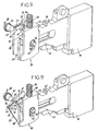
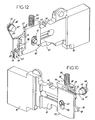
Comme représenté plus particulièrement aux figures 1, 5, 9, 11
et 12, une plaque de protection 57 pourvue d'une face interne 58 est rapportée
de l'autre côté de la queue 41 du pêne 10. Cette plaque de protection 57
présente une lumière 59 oblongue traversée par l'axe 43 transversal solidaire
du coffre 2. Par ailleurs, en partie haute de sa face interne 58, la plaque de
protection 57 présente une protubérance 60 comprenant une dent 61
prolongée par un ergot 62.As shown more particularly in FIGS. 1, 5, 9, 11
and 12, a
De plus, une rainure 64 parallèle à la queue 41 du pêne 10 est
creusée au sommet de la protubérance 60 et constitue un logement apte à
accueillir une première branche 65 d'un ressort de torsion 66 placé autour d'un
élément fixe 67 solidaire de la serrure de porte 1. Comme représenté à la
figure 1, la seconde branche 68 de ce ressort de torsion 66 est prévue pour
venir en butée contre le retour 69 de l'un des deux capots inférieurs 4. Cet
élément fixe 67 surplombe la gorge 20 ainsi que la plaque de protection 57, et
est décalé par rapport à ces dernières.In addition, a
Comme représenté aux figures 1, 7 et 8, en fonctionnement
normal, la gorge 20 et la plaque de protection 57 sont renvoyées,
respectivement par le ressort de compression 50 et le ressort de torsion 66,
vers la queue 41 du pêne 10. Dans cette position, l'une des dents 46 de la
queue 41 de pêne 10 est logée dans l'évidement 45 présenté par
l'épaulement 44 de la gorge 20 de façon à bloquer le pêne 10 en translation, la
dent 61 de la protubérance 60 repose sur la queue 41 du pêne 10, et l'ergot 62
de la protubérance 60 est inséré entre l'épaulement 44 et l'élément de butée 47
ménagés dans la gorge 20. Plus précisément, l'ergot 62 est prévu pour venir
en appui contre la surface de contact 48 sensiblement plane de l'élément de
butée 47.As shown in FIGS. 1, 7 and 8, in operation
normal, the
Comme on peut le déduire de la figure 1, lorsqu'une personne
introduit la clé 21 dans le barillet 12 afin de verrouiller ou déverrouiller le
pêne 10, le panneton 15 logé dans le coffre 2 est entraíné en rotation, ou bien
dans le sens des aiguilles d'une montre, ou bien dans le sens trigonométrique.
Ce faisant, le panneton 15 entraíne une couronne 70 en rotation et vient
simultanément au contact de la gorge 20 et de la plaque de protection 57.
Durant la première moitié de sa course, le panneton 15 exerce des contraintes
en partie basse de la gorge 20 et de la plaque de protection 57, et provoque le
déplacement en translation vers le haut de ces dernières à l'encontre
respectivement du ressort de compression 50 et du ressort de torsion 66. Au
cours de cette translation vers le haut, la gorge 20 et la plaque de protection 57
restent immobiles l'une par rapport à l'autre, et il en découle que l'ergot 62
demeure en appui contre la surface de contact 48 de l'élément de butée 47.
Lorsque le panneton 15 atteint le point le plus haut, les dents 46 de la
queue 41 du pêne 10 sont désengagées de la gorge 20, et le pêne de
condamnation 10 peut alors être entraíné en translation par ledit panneton 15
au cours de la seconde moitié de sa course. Durant cette seconde moitié de
course, la gorge 20 et la plaque de protection 57 sont alors animées d'un
mouvement de translation vers le bas sous l'effet du ressort de compression 50
et du ressort de torsion 66 qui se détendent progressivement. Lorsque le
panneton 15 a atteint le point le plus bas, l'une des dents 46 de la queue 41 du
pêne 10 est logée dans l'évidement 45 de la gorge 20, et il en découle que le
pêne 10 est bloqué en translation. De même que précédemment, durant cette
translation vers le bas, la gorge 20 et la plaque de protection 57 restent
immobiles l'une par rapport à l'autre, et par conséquent l'ergot 62 demeure en
appui contre la surface de contact 48 de l'élément de butée 47.As can be seen from Figure 1, when a person
key 21 into the
En revanche, au cours d'une tentative d'effraction, le risque que le
cambrioleur réussisse à déplacer simultanément la gorge 20 et la plaque de
protection 57 est très faible. En effet, compte tenu des faibles dimensions de la
surface de contact 48 de l'élément de butée 47, le moindre déplacement relatif
de la plaque de protection 57 par rapport à la gorge 20, comme représenté à la
figure 9, ou bien de la gorge 20 par rapport à la plaque de protection 57,
comme représenté à la figure 10, provoque le désengagement de l'ergot 62 de
l'élément de butée 47. La plaque de protection 57 est alors entraínée en
rotation par la première branche 65 du ressort de torsion 66 qui cherche à se
détendre. Comme représenté à la figure 11, pour permettre le libre pivotement
de la plaque de protection 57 autour de l'axe 43, un dégagement 71 est
avantageusement ménagé à l'arrière de la queue 41 du pêne 10. Enfin, comme
représenté à la figure 12, lorsque la plaque de protection 57 a totalement pivoté
autour de l'axe 43, la dent 61 se retrouve sur la trajectoire de la queue 41 du
pêne 10 et interdit donc tout retour en arrière de ce dernier. Un tel dispositif de
protection de la gorge 20 de la serrure de porte 1 permet donc bien de lutter
efficacement contre les tentatives d'effraction.On the other hand, during an attempted break-in, the risk that the
burglar manages to simultaneously move the
Bien que l'invention ait été décrite en liaison avec des exemples particuliers de réalisation, il est bien évident qu'elle n'y est nullement limitée et qu'elle comprend tous les équivalents techniques des moyens décrits ainsi que leurs combinaisons si celles-ci entrent dans le cadre de l'invention.Although the invention has been described in connection with examples particular achievements, it is quite obvious that it is by no means that it includes all the technical equivalents of the means described as well as their combinations if they fall within the scope of the invention.
Claims (13)
Applications Claiming Priority (2)
| Application Number | Priority Date | Filing Date | Title |
|---|---|---|---|
| FR0401117A FR2866046B1 (en) | 2004-02-05 | 2004-02-05 | DOOR LOCK WITH REINFORCED CHEST |
| FR0401117 | 2004-02-05 |
Publications (2)
| Publication Number | Publication Date |
|---|---|
| EP1580355A1 true EP1580355A1 (en) | 2005-09-28 |
| EP1580355B1 EP1580355B1 (en) | 2006-08-23 |
Family
ID=34778539
Family Applications (1)
| Application Number | Title | Priority Date | Filing Date |
|---|---|---|---|
| EP20050002127 Active EP1580355B1 (en) | 2004-02-05 | 2005-02-02 | Door lock with a reinforced case |
Country Status (3)
| Country | Link |
|---|---|
| EP (1) | EP1580355B1 (en) |
| DE (1) | DE602005000082D1 (en) |
| FR (1) | FR2866046B1 (en) |
Cited By (1)
| Publication number | Priority date | Publication date | Assignee | Title |
|---|---|---|---|---|
| DE102011050534A1 (en) * | 2011-05-20 | 2012-11-22 | Sebastian Callens | Mortise locking device for e.g. door handle in door leaf of room door, has two box-shaped housing portions whose respective height and depth are dimensioned such that connectors of universal adapter plate are obscured from housing portions |
Families Citing this family (1)
| Publication number | Priority date | Publication date | Assignee | Title |
|---|---|---|---|---|
| FR2963634B1 (en) * | 2010-08-06 | 2012-09-07 | Bricard | DOOR LOCK COMPRISING A THROAT PROTECTION DEVICE |
Citations (6)
| Publication number | Priority date | Publication date | Assignee | Title |
|---|---|---|---|---|
| DE7004312U (en) * | 1970-02-07 | 1970-05-21 | Tiefenthal Geb | LOCK, IN PARTICULAR DOOR LOCK. |
| DE1703058A1 (en) * | 1968-03-27 | 1972-04-13 | Hans Bruegemann | Lock with tumbler slider |
| GB1548298A (en) * | 1975-04-30 | 1979-07-11 | Gkn Stenman Ab | Locks and to a method of protecting lock mechanism |
| DE3030393A1 (en) * | 1980-08-12 | 1982-02-18 | Fa. Wilhelm Karrenberg, 5620 Velbert | Drill resistant mortice door lock - has bottom blocking plate and rear angular plate protecting tumbler plate |
| DE3111247A1 (en) * | 1981-03-21 | 1982-10-21 | Fa. Wilhelm Karrenberg, 5620 Velbert | Mortise lock |
| FR2761395A1 (en) * | 1997-04-01 | 1998-10-02 | Vachette Sa | Improved lock to prevent burglaries |
-
2004
- 2004-02-05 FR FR0401117A patent/FR2866046B1/en not_active Expired - Fee Related
-
2005
- 2005-02-02 EP EP20050002127 patent/EP1580355B1/en active Active
- 2005-02-02 DE DE200560000082 patent/DE602005000082D1/en active Active
Patent Citations (6)
| Publication number | Priority date | Publication date | Assignee | Title |
|---|---|---|---|---|
| DE1703058A1 (en) * | 1968-03-27 | 1972-04-13 | Hans Bruegemann | Lock with tumbler slider |
| DE7004312U (en) * | 1970-02-07 | 1970-05-21 | Tiefenthal Geb | LOCK, IN PARTICULAR DOOR LOCK. |
| GB1548298A (en) * | 1975-04-30 | 1979-07-11 | Gkn Stenman Ab | Locks and to a method of protecting lock mechanism |
| DE3030393A1 (en) * | 1980-08-12 | 1982-02-18 | Fa. Wilhelm Karrenberg, 5620 Velbert | Drill resistant mortice door lock - has bottom blocking plate and rear angular plate protecting tumbler plate |
| DE3111247A1 (en) * | 1981-03-21 | 1982-10-21 | Fa. Wilhelm Karrenberg, 5620 Velbert | Mortise lock |
| FR2761395A1 (en) * | 1997-04-01 | 1998-10-02 | Vachette Sa | Improved lock to prevent burglaries |
Cited By (1)
| Publication number | Priority date | Publication date | Assignee | Title |
|---|---|---|---|---|
| DE102011050534A1 (en) * | 2011-05-20 | 2012-11-22 | Sebastian Callens | Mortise locking device for e.g. door handle in door leaf of room door, has two box-shaped housing portions whose respective height and depth are dimensioned such that connectors of universal adapter plate are obscured from housing portions |
Also Published As
| Publication number | Publication date |
|---|---|
| EP1580355B1 (en) | 2006-08-23 |
| FR2866046A1 (en) | 2005-08-12 |
| DE602005000082D1 (en) | 2006-10-05 |
| FR2866046B1 (en) | 2006-05-26 |
Similar Documents
| Publication | Publication Date | Title |
|---|---|---|
| EP2611656A1 (en) | Motor vehicle steering lock | |
| CA2337276C (en) | Closing device with selective locking | |
| FR2708025A1 (en) | Device for the protection of the cylinder plug of a door lock | |
| EP1580355B1 (en) | Door lock with a reinforced case | |
| EP1561885B1 (en) | Protection device for a tumbler of a door lock | |
| EP2123851A1 (en) | Lock mechanism comprising a shield | |
| EP1580356B1 (en) | Device for the protection of a door cylinder lock | |
| FR2888602A1 (en) | Door lock for e.g. room, has case with limiter movable between active and inactive positions, where limiter is displaced towards active position, when cylinder does not retain fixation screw in its normal position | |
| EP1308585B1 (en) | Lock with anti-burglary safety block | |
| FR2471469A1 (en) | STOP FOR PIVOTING DOOR | |
| EP0411969B1 (en) | Door protection device | |
| CA2914127C (en) | Device for coupling two half-cylinders | |
| EP0252781A2 (en) | Adjustable striker, and tamper-proof mounting means | |
| CH680521A5 (en) | ||
| FR3034124A1 (en) | DEVICE ANFEFRATING A STORAGE | |
| FR2682985A1 (en) | Reversible housing for controlling and disabling an anti-panic lock with pushbar | |
| EP0633377B1 (en) | Safety lock | |
| FR2811696A1 (en) | Sliding door lock fitting comprises case fixed in door mounting slot by fixing cradles one of which has jaw able to translate relative to case between encastring and fixing positions | |
| BE1014947A3 (en) | Fitting lock sliding roof and siding a separate technical unit, mounting method and opening of bracket team as. | |
| EP1359271A1 (en) | Mechanical box locking device | |
| FR2469533A1 (en) | Casement bolt door lock - has dead bolt with stud actuating push rods for casement bolts at door ends | |
| EP3819445A1 (en) | Safety device for window handle | |
| EP0270423B1 (en) | Process for equipping a bolt and keeper unit with protection and reinforcement fittings, and unit obtained by this process | |
| FR2588033A1 (en) | Drum-type lock with improved safety for preventing lock picking | |
| FR2931506A1 (en) | Lock mechanism, has burglar-proof unit arranged for memorizing displacement of front block with respect to rear block and controlling recognizing spacer of rod of key and bolt operating mechanism |
Legal Events
| Date | Code | Title | Description |
|---|---|---|---|
| PUAI | Public reference made under article 153(3) epc to a published international application that has entered the european phase |
Free format text: ORIGINAL CODE: 0009012 |
|
| AK | Designated contracting states |
Kind code of ref document: A1 Designated state(s): AT BE BG CH CY CZ DE DK EE ES FI FR GB GR HU IE IS IT LI LT LU MC NL PL PT RO SE SI SK TR |
|
| AX | Request for extension of the european patent |
Extension state: AL BA HR LV MK YU |
|
| 17P | Request for examination filed |
Effective date: 20050827 |
|
| GRAP | Despatch of communication of intention to grant a patent |
Free format text: ORIGINAL CODE: EPIDOSNIGR1 |
|
| AKX | Designation fees paid |
Designated state(s): DE ES FR GB IT |
|
| GRAS | Grant fee paid |
Free format text: ORIGINAL CODE: EPIDOSNIGR3 |
|
| GRAA | (expected) grant |
Free format text: ORIGINAL CODE: 0009210 |
|
| AK | Designated contracting states |
Kind code of ref document: B1 Designated state(s): DE ES FR GB IT |
|
| PG25 | Lapsed in a contracting state [announced via postgrant information from national office to epo] |
Ref country code: IT Free format text: LAPSE BECAUSE OF FAILURE TO SUBMIT A TRANSLATION OF THE DESCRIPTION OR TO PAY THE FEE WITHIN THE PRESCRIBED TIME-LIMIT;WARNING: LAPSES OF ITALIAN PATENTS WITH EFFECTIVE DATE BEFORE 2007 MAY HAVE OCCURRED AT ANY TIME BEFORE 2007. THE CORRECT EFFECTIVE DATE MAY BE DIFFERENT FROM THE ONE RECORDED. Effective date: 20060823 Ref country code: GB Free format text: LAPSE BECAUSE OF FAILURE TO SUBMIT A TRANSLATION OF THE DESCRIPTION OR TO PAY THE FEE WITHIN THE PRESCRIBED TIME-LIMIT Effective date: 20060823 |
|
| REG | Reference to a national code |
Ref country code: GB Ref legal event code: FG4D Free format text: NOT ENGLISH |
|
| REF | Corresponds to: |
Ref document number: 602005000082 Country of ref document: DE Date of ref document: 20061005 Kind code of ref document: P |
|
| PG25 | Lapsed in a contracting state [announced via postgrant information from national office to epo] |
Ref country code: DE Free format text: LAPSE BECAUSE OF FAILURE TO SUBMIT A TRANSLATION OF THE DESCRIPTION OR TO PAY THE FEE WITHIN THE PRESCRIBED TIME-LIMIT Effective date: 20061124 |
|
| PG25 | Lapsed in a contracting state [announced via postgrant information from national office to epo] |
Ref country code: ES Free format text: LAPSE BECAUSE OF FAILURE TO SUBMIT A TRANSLATION OF THE DESCRIPTION OR TO PAY THE FEE WITHIN THE PRESCRIBED TIME-LIMIT Effective date: 20061204 |
|
| GBV | Gb: ep patent (uk) treated as always having been void in accordance with gb section 77(7)/1977 [no translation filed] |
Effective date: 20060823 |
|
| PLBE | No opposition filed within time limit |
Free format text: ORIGINAL CODE: 0009261 |
|
| STAA | Information on the status of an ep patent application or granted ep patent |
Free format text: STATUS: NO OPPOSITION FILED WITHIN TIME LIMIT |
|
| 26N | No opposition filed |
Effective date: 20070524 |
|
| REG | Reference to a national code |
Ref country code: FR Ref legal event code: PLFP Year of fee payment: 12 |
|
| REG | Reference to a national code |
Ref country code: FR Ref legal event code: PLFP Year of fee payment: 13 |
|
| REG | Reference to a national code |
Ref country code: FR Ref legal event code: PLFP Year of fee payment: 14 |
|
| PGFP | Annual fee paid to national office [announced via postgrant information from national office to epo] |
Ref country code: FR Payment date: 20230116 Year of fee payment: 19 |