EP1578573B1 - Vorrichtung zur herstellung von betonformsteinen - Google Patents
Vorrichtung zur herstellung von betonformsteinen Download PDFInfo
- Publication number
- EP1578573B1 EP1578573B1 EP03789060A EP03789060A EP1578573B1 EP 1578573 B1 EP1578573 B1 EP 1578573B1 EP 03789060 A EP03789060 A EP 03789060A EP 03789060 A EP03789060 A EP 03789060A EP 1578573 B1 EP1578573 B1 EP 1578573B1
- Authority
- EP
- European Patent Office
- Prior art keywords
- mould
- insert
- mount
- frame
- sensor
- Prior art date
- Legal status (The legal status is an assumption and is not a legal conclusion. Google has not performed a legal analysis and makes no representation as to the accuracy of the status listed.)
- Expired - Lifetime
Links
- 238000000465 moulding Methods 0.000 claims abstract description 11
- 238000000034 method Methods 0.000 claims abstract description 3
- 230000033001 locomotion Effects 0.000 claims description 25
- 238000013016 damping Methods 0.000 claims description 7
- 238000004519 manufacturing process Methods 0.000 claims description 4
- 239000013013 elastic material Substances 0.000 claims description 3
- 239000000463 material Substances 0.000 claims 1
- 238000006073 displacement reaction Methods 0.000 abstract 4
- 238000011156 evaluation Methods 0.000 description 4
- 238000005192 partition Methods 0.000 description 4
- 238000003780 insertion Methods 0.000 description 3
- 230000037431 insertion Effects 0.000 description 3
- 238000004026 adhesive bonding Methods 0.000 description 2
- 238000013461 design Methods 0.000 description 2
- 238000001514 detection method Methods 0.000 description 2
- 238000005259 measurement Methods 0.000 description 2
- 230000001133 acceleration Effects 0.000 description 1
- 230000037237 body shape Effects 0.000 description 1
- 230000000295 complement effect Effects 0.000 description 1
- 238000010276 construction Methods 0.000 description 1
- 238000011109 contamination Methods 0.000 description 1
- 230000001419 dependent effect Effects 0.000 description 1
- 230000001066 destructive effect Effects 0.000 description 1
- 238000011161 development Methods 0.000 description 1
- 230000018109 developmental process Effects 0.000 description 1
- 238000009826 distribution Methods 0.000 description 1
- 238000003754 machining Methods 0.000 description 1
- 230000013011 mating Effects 0.000 description 1
- 239000002184 metal Substances 0.000 description 1
- 238000002360 preparation method Methods 0.000 description 1
- 238000001228 spectrum Methods 0.000 description 1
- 230000000007 visual effect Effects 0.000 description 1
Images



Classifications
-
- B—PERFORMING OPERATIONS; TRANSPORTING
- B28—WORKING CEMENT, CLAY, OR STONE
- B28B—SHAPING CLAY OR OTHER CERAMIC COMPOSITIONS; SHAPING SLAG; SHAPING MIXTURES CONTAINING CEMENTITIOUS MATERIAL, e.g. PLASTER
- B28B17/00—Details of, or accessories for, apparatus for shaping the material; Auxiliary measures taken in connection with such shaping
-
- B—PERFORMING OPERATIONS; TRANSPORTING
- B28—WORKING CEMENT, CLAY, OR STONE
- B28B—SHAPING CLAY OR OTHER CERAMIC COMPOSITIONS; SHAPING SLAG; SHAPING MIXTURES CONTAINING CEMENTITIOUS MATERIAL, e.g. PLASTER
- B28B17/00—Details of, or accessories for, apparatus for shaping the material; Auxiliary measures taken in connection with such shaping
- B28B17/0063—Control arrangements
- B28B17/0081—Process control
Definitions
- the invention relates to a device for producing concrete blocks.
- the production of concrete blocks is typically carried out in molding machines, in which a mold insert is held with one or more mold cavities over a mold frame and pressed after filling the mold cavities with concrete mass during a shaking on a Rüttelunterlage.
- a mold with a mold frame and held in this mold insert is z. B. from the DE 195 08 152 A1 known, wherein the mold insert is held by elastic damping elements to a small extent movable in the mold frame.
- the invention has for its object to provide an advantageous device for the production of concrete blocks and a method for determining a movement size for it.
- the insertion and non-destructive release of the sensor into and out of the receptacle allows the user of the mold insert to use his own measuring system and / or the use of the same sensors, for several different uses, possibly also from different manufacturers and / or the measurement of movement quantities at other positions of the molding machine.
- the sensor can be glued in another advantageous manner also on a belonging to the recording surface of the mold insert directly or with the interposition of a connecting plate, in particular a connecting plate with a threaded hole or a threaded bolt.
- the receptacle for the sensor advantageously includes a recess between facing surfaces of mold insert and mold frame, which are otherwise typically made close together.
- the recess is bounded on at least four sides in the main direction of an orthogonal coordinate system by surfaces of mold insert and mold frame.
- Embodiments in which the recess is open to the side and / or downwards are preferred.
- the dimensions of such a recess amount between opposite limiting surfaces advantageously in all directions at least 10 mm.
- damping means in particular rubber-elastic damping plates are inserted between the mold insert and the mold frame in a conventional manner.
- the damping means are particularly advantageous between vertically spaced opposite surfaces of mold insert and mold frame, z. B. in the form of from the DE 195 08 152 A1 known, interlocking projections and depressions on mold frame and mold insert.
- a plurality of sensor receptacles are arranged distributed in a plane parallel to the support plane of the mold insert on the Rüttelunterlage.
- several receptacles are arranged in a symmetrical, in particular twice mirror-symmetrical distribution along the circumference of the mold insert in the edge region thereof. If the design of the mold insert allows it, advantageously at least one sensor receptacle can be spaced from the edge of the mold insert, in particular in the mold insert Be provided area of the center and / or between two adjacent mold cavities.
- a sensor receptacle contains a protruding horizontally from an outer wall of the mold insert projection, which is designed for attachment of a sensor element to this projection, in particular for a screw fastening.
- the projection may be formed as an extension of the outer wall of the mold insert or attached to the outer wall, in particular welded.
- the sensor receptacle may include a breakthrough in the wall of the mold frame assigning the mold insert, preferably at a corner of the mold insert, in particular in an embodiment of the mold frame with a designed as a plate or sheet wall.
- the mold insert is held in the mold frame so that during the shaking a small relative movement, in particular by insertion of elastic elements between the mold frame and mold insert, is possible.
- at least one motion sensor is mounted on the mold frame and the evaluation device is set up to determine relative movements between the mold frame and mold insert, for example by differentiating between different sensor signals.
- Fig. 1 is schematically a device with a mold insert FE having a substantially rectangular outline and with a mold insert in the longitudinal direction LR with longitudinal strips LL and outlined in the transverse direction QR with transverse strips QL circumferentially FR frame.
- Longitudinal and transverse strips of the mold frame can be designed as a one-piece mold frame or connected to each other as a built mold frame, in particular welded or screwed.
- On the transverse strips QL flange strips MF are mounted outwardly, by means of which held the mold insert in the molding machine, is moved and pressed in particular during a shaking on a Rüttelunterlage.
- the structure of the mold frame in detail is subordinate to the present invention and various embodiments known to those skilled in the art can be used.
- the mold frame can also be given only by two transverse strips without connecting longitudinal strips.
- the mold insert is typically a one-piece mold block with a substantially rectangular profile of the outer wall in plan view and with a plurality of mold cavities FN separated by vertical partitions TW.
- Different special forms are known.
- receptacles for sensor elements for detecting motion variables are prepared on the mold insert.
- Sensors are advantageously detachably mountable in the receptacles, preferably by screwing and / or gluing. Through the prepared shots can be easily done by the customer or by service staff of the machine manufacturer or in particular the manufacturer of the mold inserts and optionally the mold frame adjustment of the machine and / or a control of the mold insert on site and in the operation of the concrete block production can be made.
- the mold inserts are typically delivered with prepared sensor mounts, but without sensors, but can also be sensor-equipped.
- the inventively provided on the mold insert sensor receptacles are particularly advantageous in arrangements in which the mold insert can be dynamically deflected within the mold frame relative to this to a small extent from a rest position, especially during the Studttelvorgangs.
- elastic, in particular rubber-elastic damping means are inserted for this purpose between the mold frame and mold insert.
- the Fig. 1 shows schematically preferred positions of the invention provided on the mold insert sensor recordings.
- a first group of such positions indicated by I is provided in the region of the outer wall of the mold insert on the longitudinal sides.
- at least two sensor receptacles are provided spatially distributed relative to positions lying symmetrically with respect to a center plane parallel to the longitudinal direction LR or to the transverse direction QR, preferably four receptacles in positions lying symmetrically to both center planes.
- the recordings of such a group are preferably all in one plane.
- the horizontal distances DL of the sensor positions from the corners EE of the mold insert in the longitudinal direction LR are advantageously not more than 100 mm, in particular not more than 50 mm.
- Another, second group of positions designated by II for sensor receptacles is provided in the region of the outer wall of the mold insert on the transverse sides.
- Particularly advantageous embodiments can here in to the first group of positions I be provided analogous manner. Reference is made to the above comments on positions I.
- the first group of positions I and the second group of positions II are typically prepared alternatively or filled with sensor images.
- sensor receptacles it is also possible for sensor receptacles to be provided both at positions I and at positions II on one and the same mold insert.
- sensor receptacles may also be formed at other positions in the region of the outer wall, in particular in the lateral centers. Corner-like positions are preferred.
- Sensor images of a group are preferably within a horizontal plane, i. H. arranged at the same distance from the lower support level of the mold insert.
- sensor receptacles can also be provided within the enclosed field between adjacent mold cavities, which in Fig. 1 as positions III are given by way of example, wherein in particular a position in the intersection of the LR and QR parallel center plane or at the intersection of the diagonal of the mold insert is preferred.
- internal sensor receptacles is advantageously a leading from the sensor receptacle to the outer wall of the mold insert line channel, z. B. in the form of double-shell partitions, provided.
- the duct can be prepared for the demand-based insertion of an electrical connection line, but can also permanently contain such a connection line between a receiving-side and an outer-wall-side connection.
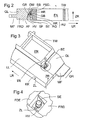
- Fig. 2 shows in horizontal viewing direction along a longitudinal side or in particular a transverse side of a sensor receptacle in a particularly advantageous detachable connection between a mold insert FED and a mold frame FRD.
- An oblique view from below Fig. 2 is in Fig. 3 outlined.
- a relief structure HR in the form of a projection directed horizontally away from the mold cavities FN is formed on an outer wall of the mold insert FED over at least part of the length of the side wall.
- the projection forms a horizontal profile along the outer wall.
- the relief has in particular an upwardly facing, preferably obliquely tilted against the horizontal bearing surface, which faces a parallel, downwardly facing counter surface of a counter-relief GR in the mold frame FRD.
- the counter-relief forms a recess in the mold frame, which can extend below the mating surface again on the mold insert.
- the protrusion HR is approximately triangular in cross-section in the sketched example and the counter-relief follows this contour in the form of a likewise approximately triangular in cross-section depression in the mold frame.
- damping means DM preferably be inserted from elastic, in particular rubber-elastic material.
- the mold insert FED protrudes down beyond the mold frame and can be pressed by means of the mold frame on the support surface AF of a vibrating plate or the like.
- a holding projection HV which is preferably part of the holding profile HR and in particular can be formed at a longitudinal end of this profile, likewise protrudes from the outer wall of the mold insert into the recess of the mold frame, but does not fill it.
- the retaining projection includes a sensor abutment surface SF, which preferably points downwards, and a receiving bore GB, which can also be a threaded bore, for releasable attachment of a sensor element SE in a rigid mechanical connection with the mold insert.
- the retaining projection HV is in the example sketched by a recess AR on the profile HR at a corner EE facing the end of this profile made from this.
- the holding projection HV can also be carried out detached from the profile HR.
- the counter-relief GR in the frame FRD as shown in the example below under the retaining projection in horizontal overlap with this again on the outer wall of the mold insert can advantageously be provided in this lower area of the counter-relief below the holding projection HV a recess AG in the mold frame, which place for the housing of the sensor element attached to the mold insert and / or for an electrical connection cable between the sensor and the measuring or evaluation device.
- the receptacle for the sensor element SE includes in Fig. 2 to Fig. 4 sketched example, both the receiving bore GB and the insert-side recess AR and the frame-side recess AG, which together form a recess AU between the mold frame and mold insert.
- the recess AU is limited in an orthogonal coordinate system, in particular with axes in the longitudinal direction LR, transverse direction QR and in the normal direction ZR of the support surface AF, in five main directions of surfaces of the mold insert FED and the mold frame FRD, wherein the dimensions of the receptacle AU between each opposing limiting Surfaces in all directions, horizontal in the example, at least 10 mm.
- the recess AU is limited in the example outlined above by the sensor contact surface of the projection HV and open at the bottom.
- An electrical supply line ZL to the sensor element SE can z. B. be performed below the mold frame to the outside to a not marked with evaluation.
- the supply line can also be advantageously outlined as outlined by a cable channel KK of the mold frame, which deviating from the sketch also down may be open in the form of a groove.
- In the counter-relief GR of the mold frame FRD is advantageously provided in an extension of the receiving bore GB also has a bore SB through which a screw, nut or the like can be used for fastening the sensor element and tightened without mold insert and mold frame must be solved from each other.
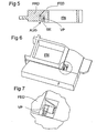
- Fig. 5 to Fig. 7 is in too Fig. 2 to Fig. 4 analog views sketched a variant, which differs from the execution Fig. 2 to Fig. 4 essentially differs by another attachment of the sensor element on the mold insert FED and the rest of the design features of the execution Fig. 2 to Fig. 4 has largely taken over.
- the sensor element SE is here by 90 ° against Fig. 2 used turned and fixed to a vertical surface of the mold insert, wherein for mounting here an embodiment is selected in which a connection plate VP mounted on the surface of the mold insert, in particular glued and carries a threaded bolt on which the sensor element is screwed.
- the orientation rotated by 90 ° enables the detection of other directional components of the movement of the mold insert, in particular in the case of the preferred sensor elements with one-dimensional motion detection.
- Fig. 8 is a side view of a section of a side wall of a mold frame FRN sketched, beyond which a mold insert FEN protrudes down and rests on the support surface AF of a vibrating table or the like.
- Fig. 9 shows a view Fig. 8 from diagonally below, Fig. 10 an enlarged section Fig. 9 .
- the mold frame may include, for example, a horizontal top plate OP and a vertical side plate SP, which may be e.g. B. welded together or, as outlined, can be made in one piece as a folded plate and in the example sketched also by a horizontal lower plate section UP can be added.
- a cover plate DB is additionally attached in a conventional manner.
- an opening AN is recessed.
- a fixedly connected to the outer wall of the mold insert FEN retaining projection projects, for example, as outlined here in the form of a welded to the outer wall of the mold insert FEN holding body AH, which is executed in the example sketched as downwardly open hollow body and both horizontal and vertical contact surfaces for the attachment of a sensor element in different orientations.
- the hollow body shape is, especially intrinsically stiff, so that the sensor element reliably detects the movement behavior of the mold insert.
- the holding body can also be configured as an angle or plate projecting from the outer wall surface of the mold insert FEN.
- the attachment of a sensor element can be inside or outside the hollow body, for. B. by screwing or gluing done.
- the holding body can also after the type of connecting plate VP Fig. 5 be executed.
- the opening AN in the side wall SP of the mold frame FRN may also be downwardly open in the form of a cut from the bottom edge of the side wall panel, particularly in the construction of the mold frame without bottom panel.
- Mold insert and mold frame are in the sketches after Fig. 8 to Fig. 10 releasably coupled by means of a tongue and groove connection, wherein in the mutually facing vertical surfaces of the mold insert and the mold frame grooves NE and NF milled and a spring EF, preferably made of metal or of an elastic material is used.
- Fig. 11 shows an embodiment for mounting a Sensorelemlents between adjacent mold cavities FNA, FNB.
- the dividing wall between the two Form nests is here clamshell with part walls TWA, TWB executed, which are predominantly close to each other, but in a receiving area have a recess AUT, in which a sensor element can be used and fixed.
- the attachment can z. B. by one of the types described, in particular using a bond.
- An electrical supply line ZL to the sensor element SE can z. B. advantageously be performed by a designed as a groove in one of the two partial walls cable channel KT.
- the recess AUT may be open at the bottom, in which case a one-piece partition wall may be provided instead of the partial walls TWA, TWB, but is preferably closed on all sides for protection against contamination.
- a sensor receptacle between adjacent mold cavities can also be advantageously designed in such a way that the cross sections of the mold cavities do not complement each other to a continuous surface except for partitions and in area sections with horizontally more spaced boundary walls of adjacent mold cavities as in Fig. 13 in a section with two adjacent mold cavities FNC, FND and boundary walls TWC, TWD a cavity FZ is recessed, in which a sensor element SE can be arranged.
- the cavity FZ is protected at the top by a cover DP against the ingress of concrete mass.
- advantageously cable management devices KF, z. B. in the form of wall openings, recesses, holes, grooves, etc. provided.
- Cable guides or cable holders for the connection cables to the sensor elements can advantageously be provided on the mold frame in order to protect them against damage by defined guidance.
- On the mold frame sensors are also provided, preferably to after Fig. 1 corresponding positions, creating differential measurements between the movements of the mold frame and mold insert can be made with elastic in the mold frame stored mold insert.
Landscapes
- Engineering & Computer Science (AREA)
- Ceramic Engineering (AREA)
- Mechanical Engineering (AREA)
- Chemical & Material Sciences (AREA)
- Automation & Control Theory (AREA)
- Moulds, Cores, Or Mandrels (AREA)
- Moulds For Moulding Plastics Or The Like (AREA)
- Devices For Post-Treatments, Processing, Supply, Discharge, And Other Processes (AREA)
- Aftertreatments Of Artificial And Natural Stones (AREA)
- Artificial Fish Reefs (AREA)
- Revetment (AREA)
- Press-Shaping Or Shaping Using Conveyers (AREA)
- Preparation Of Clay, And Manufacture Of Mixtures Containing Clay Or Cement (AREA)
Description
- Die Erfindung betrifft eine Vorrichtung zur Herstellung von Betonformsteinen.
- Die Herstellung von Betonformsteinen erfolgt typischerweise in Formmaschinen, in welchen ein Formeinsatz mit einem oder mehreren Formnestern über einen Formrahmen gehalten und nach Befüllen der Formnester mit Betonmasse während eines Rüttelvorgangs auf eine Rüttelunterlage gepresst wird.
- Die
US 5 997 271 beschreibt eine Anordnung von Formen für die maschinelle Herstellung von Formkörpern aus Beton, gemäß dem Oberbegriff des Anspruchs 1. - Aus der
DE 199 56 961 A1 ist es bekannt, bei derartigen Vorrichtungen an geeigneten Stellen, beispielsweise Tisch, Form und Auflast, Bewegungsgrößen zu messen und spektral zu analysieren. Neben einer visuellen Darstellung der Spektren können aus Abweichungen der Messgrößen von Sollwerten auch Steuersignale zur Nachregelung von Maschinenparametern abgeleitet werden. Eine derartige Regelung ist auch bereits aus derDE 199 21 145 A1 bekannt, wo z. B. eine Piezoelektronik sowohl als Aktor bei der Rüttelbewegung als auch als Sensor zur Aufnahme von Bewegungsdaten dienen kann, und offenbart dem gemäß dem Oberbegriff des Anspruchs 26. - Eine Form mit einem Formrahmen und einem in diesem gehaltenen Formeinsatz ist z. B. aus der
DE 195 08 152 A1 bekannt, wobei der Formeinsatz über elastische Dämpfungselemente in geringem Umfang beweglich in dem Formrahmen gehalten ist. - Der Erfindung liegt die Aufgabe zugrunde, eine vorteilhafte Vorrichtung zur Herstellung von Betonformsteinen sowie ein Verfahren zur Ermittlung einer Bewegungsgröße dafür anzugeben.
- Erfindungsgemäße Lösungen sind in den unabhängigen Ansprüchen beschrieben. Die abhängigen Ansprüche enthalten vorteilhafte Ausgestaltungen und Weiterbildungen der Erfindung.
- Die Vorbereitung einer Aufnahme für einen Sensor in dem Formeinsatz einer in Formrahmen und vorzugsweise von diesem lösbaren Formeinsatz unterteilten Form ermöglicht vorteilhafterweise die auf den einzelnen Formeinsatz abgestimmte Positionierung eines oder vorzugsweise mehrerer verteilter Sensoren. Gegenüber einer Anbringung des Sensors an leicht zugänglicher Stelle des Formrahmens wie in der genannten
DE 199 56 961 A1 angedeutet, ist die erfindungsgemäße Lösung, gemäß dem Oberbegriff der Ansprüche 1 und 26, zwar mit Zusatzaufwand behaftet, ermöglicht aber überraschenderweise eine erheblich bessere Beurteilung des Zustandes einer Form und deren Verhalten in der Formmaschine. Unter der Aufnahme seien dabei der Raum für den Sensor als auch die Einrichtungen zu dessen Verbindung mit dem Formeinsatz verstanden. - Durch die bereits vom Hersteller des Formeinsatzes vorbereitete Aufnahme für den Sensor kann diese an z. B. hinsichtlich Aussagekraft der Messwerte und/oder Stabilität des Formeinsatzes optimierter Position angeordnet sein. Das Einsetzen und zerstörungsfreie Lösen des Sensors in die bzw. aus der Aufnahme, vorzugsweise über eine Schraubenverbindung, insbesondere eine Gewindebohrung in der Aufnahme, ermöglicht dem Benutzer des Formeinsatzes die Verwendung eines eigenen Messsystems und/oder die Verwendung derselben Sensoren, für mehrere unterschiedliche Einsätze, gegebenenfalls auch von verschiedenen Herstellern und/oder die Messung von Bewegungsgrößen an anderen Positionen der Formmaschine. Der Sensor kann in anderer vorteilhafter Weise auch auf eine zu der Aufnahme gehörende Fläche des Formeinsatzes unmittelbar oder unter Zwischenfügung einer Verbindungsplatte, insbesondere einer Verbindungsplatte mit einer Gewindebohrung oder einem Gewindebolzen, aufgeklebt werden.
- Die Aufnahme für den Sensor beinhaltet vorteilhafterweise eine Aussparung zwischen einander zuweisenden Flächen von Formeinsatz und Formrahmen, welche ansonsten typischerweise eng aneinander anliegend ausgeführt sind. Vorzugsweise ist die Aussparung an wenigstens vier Seiten in Hauptrichtung eines orthogonalen Koordinatensystems durch Flächen von Formeinsatz und Formrahmen begrenzt. Bevorzugt sind Ausführungen, in welchen die Aussparung zur Seite und/oder nach unten offen ist. Die Abmessungen einer solchen Aussparung betragen zwischen gegenüberliegenden begrenzenden Flächen vorteilhafterweise in alle Richtungen wenigstens 10 mm.
- Vorzugsweise sind zwischen Formeinsatz und Formrahmen in an sich bekannter Weise Dämpfungsmittel, insbesondere gummielastische Dämpfungsplatten eingefügt. Die Dämpfungsmittel sind insbesondere von Vorteil zwischen sich vertikal beabstandet gegenüberstehenden Flächen von Formeinsatz und Formrahmen, z. B. in Form von aus der
DE 195 08 152 A1 bekannten, ineinander greifenden Vorsprüngen und Vertiefungen an Formrahmen und Formeinsatz. - Vorzugsweise sind mehrere Sensoraufnahmen in einer zur Auflageebene des Formeinsatzes auf der Rüttelunterlage parallelen Ebene verteilt angeordnet. Insbesondere können vorteilhafterweise mehrere Aufnahmen im Randbereich des Formeinsatzes an, in oder nahe bei dessen seitlicher Außenwand vorgesehen sein. Bevorzugt sind dabei Positionen der Aufnahmen, welche an einer Ecke des Formeinsatzes liegen oder von einer Ecke entlang einer Seitenfläche um eine Distanz abgesetzt sind, welche maximal 100 mm, insbesondere maximal 50 mm beträgt.
- Gemäß einer vorteilhaften Ausführung sind entlang des Umfangs des Formeinsatzes in dessen Randbereich mehrere Aufnahmen in symmetrischer, insbesondere zweifach spiegelsymmetrischer Verteilung angeordnet. Sofern die Gestaltung des Formeinsatzes es zulässt, kann günstigerweise wenigstens eine Sensoraufnahme vom Rand des Formeinsatzes beabstandet, insbesondere im Bereich von dessen Mitte und/oder zwischen zwei benachbarten Formnestern vorgesehen sein.
- Eine vorteilhafte Ausführung einer Sensoraufnahme sieht vor, dass diese einen von einer Außenwand des Formeinsatzes horizontal abstehenden Vorsprung enthält, welcher zur Befestigung eines Sensorelements an diesem Vorsprung ausgebildet ist, insbesondere für eine Schraubbefestigung. Der Vorsprung kann als Fortsatz der Außenwand des Formeinsatzes ausgebildet oder an der Außenwand befestigt, insbesondere angeschweißt sein. In anderer Ausführung der Sensoraufnahme kann diese einen Durchbruch in der dem Formeinsatz zuweisenden Wand des Formrahmens, vorzugsweise an einer Ecke des Formeinsatzes beinhalten, insbesondere bei einer Ausführung des Formrahmens mit einer als Platte oder Blech ausgebildeten Wand.
- Der Formeinsatz ist im Formrahmen so gehalten, dass beim Rüttelvorgang eine geringe Relativbewegung, insbesondere durch Einfügung elastischer Elemente zwischen Formrahmen und Formeinsatz, möglich ist. Zusätzlich ist am Formrahmen wenigstens ein Bewegungssensor angebracht und ist die Auswerteeinrichtung zur Ermittlung von Relativbewegungen zwischen Formrahmen und Formeinsatz eingerichtet, beispielsweise durch Differenzbildung zwischen verschiedenen Sensorsignalen.
- Die Erfindung ist nachfolgend anhand bevorzugter Ausführungsbeispiele unter Bezugnahme auf die Abbildungen noch eingehend veranschaulicht. Dabei zeigt:
-
Fig. 1 bevorzugte Sensorpositionen in einem Formeinsatz in Draufsicht, -
Fig. 2 ein Schnittbild einer ersten Ausführung einer Sensoraufnahme, -
Fig. 3 die Ausführung nachFig. 2 in Schrägansicht von unten, -
Fig. 4 einen vergrößerten Ausschnitt ausFig. 3 , -
Fig. 5 eine zuFig. 2 analoge Ausführung mit anderer Sensorausrichtung, -
Fig. 6 eine Schrägansicht von unten auf die Ausführung nachFig. 5 , -
Fig. 7 einen vergrößerten Ausschnitt ausFig. 6 , -
Fig. 8 ein Schnittbild einer weiteren vorteilhaften Ausführungsform, -
Fig. 9 eine Schrägansicht der Ausführungsform nachFig. 8 , -
Fig. 10 eine Ausschnittsvergrößerung ausFig. 9 , -
Fig. 11 eine Ausführung einer Aufnahme in Position III nachFig. 1 , -
Fig. 12 eine Schrägansicht auf die Ausführung nachFig. 11 . - In
Fig. 1 ist schematisch eine Vorrichtung mit einem Formeinsatz FE mit im wesentlichen rechteckigem Umriss und mit einem den Formeinsatz in Längsrichtung LR mit Längsleisten LL und in Querrichtung QR mit Querleisten QL umlaufend einfassenden Formrahmen FR skizziert. Längsteisten und Querleisten des Formrahmens können als einstückiger Formrahmen ausgeführt oder als gebauter Formrahmen miteinander verbunden, insbesondere verschweißt oder verschraubt sein. An den Querleisten QL sind nach außen weisend Flanschleisten MF angebracht, mittels derer der Formeinsatz in der Formmaschine gehalten, bewegt und insbesondere während eines Rüttelvorgangs auf eine Rüttelunterlage gedrückt wird. Der Aufbau des Formrahmens im einzelnen ist für die vorliegende Erfindung nachrangig und verschiedene dem Fachmann an sich bekannte Ausführungen können zum Einsatz kommen. Insbesondere kann der Formrahmen auch lediglich durch zwei Querleisten ohne verbindende Längsleisten gegeben sein. - Für die lösbare, d. h. insbesondere nicht geschweißte Verbindung zwischen Formrahmen und Formeinsatz sind eine Mehrzahl von verschiedenen Ausführungen an sich bekannt, welche, soweit im Einzelfall besonderer Ausführungen von Sensoraufnahmen nicht eingeschränkt, bei der vorliegenden Erfindung einsetzbar sind.
- Der Formeinsatz ist typischerweise ein einstückiger Formblock mit in Draufsicht im wesentlichen rechteckigem Verlauf der Außenwand und mit einer Mehrzahl von durch vertikale Trennwände TW separierten Formnestern FN. Abweichende Sonderformen sind bekannt.
- Die an sich bekannten Ausführungen von Formrahmen, Formeinsatz und deren lösbarer Verbindung können in unterschiedlichen Kombinationen vorliegen. Die nachfolgenden Ausführungsbeispiele sind hierzu lediglich als eine Auswahl aus den möglichen und bekannten Varianten zu verstehen.
- Wesentlich an der vorliegenden Erfindung ist, dass an dem Formeinsatz Aufnahmen für Sensorelemente zur Erfassung von Bewegungsgrößen, vorzugsweise Beschleunigungssensoren vorbereitet sind. Sensoren sind vorteilhafterweise lösbar in den Aufnahmen befestigbar, vorzugsweise durch Verschraubung und/oder Verklebung. Durch die vorbereiteten Aufnahmen kann auf einfache Weise durch den Kunden oder durch Servicemitarbeiter des Maschinenherstellers oder insbesondere auch des Herstellers der Formeinsätze und gegebenenfalls der Formrahmen eine Einstellung der Maschine und/oder eine Kontrolle des Formeinsatzes vor Ort und im Betrieb der Betonsteinfertigung vorgenommen werden. Die Formeinsätze werden typischerweise mit vorbereiteten Sensoraufnahmen, aber ohne Sensoren ausgeliefert, können aber auch sensorbestückt sein. Die erfindungsgemäß am Formeinsatz vorgesehenen Sensoraufnahmen sind besonders vorteilhaft bei Anordnungen, bei welchen der Formeinsatz innerhalb des Formrahmens relativ zu diesem in geringem Umfang aus einer Ruhelage dynamisch ausgelenkt werden kann, insbesondere während des Rüttelvorgangs. Vorzugsweise sind hierfür zwischen Formrahmen und Formeinsatz elastische, insbesondere gummielastische Dämpfungsmittel eingefügt.
- Die
Fig. 1 zeigt schematisch bevorzugte Positionen der erfindungsgemäß am Formeinsatz vorgesehenen Sensoraufnahmen. Eine erste Gruppe von solchen mit I gekennzeichneten Positionen ist im Bereich der Außenwand des Formeinsatzes an den Längsseiten vorgesehen. Vorteilhafterweise sind wenigstens zwei Sensoraufnahmen an bezüglich einer zur Längsrichtung LR oder zur Querrichtung QR parallelen Mittelebene symmetrisch liegenden Positionen, vorzugsweise vier Aufnahmen in zu beiden Mittelebenen symmetrisch liegenden Positionen räumlich verteilt vorgesehen. In vertikaler Richtung, d. h. senkrecht zur Zeichenebene derFig. 1 , liegen die Aufnahmen einer solchen Gruppe vorzugsweise alle in einer Ebene. Die horizontalen Abstände DL der Sensorpositionen von den Ecken EE des Formeinsatzes in Längsrichtung LR betragen vorteilhafterweise maximal 100 mm, insbesondere maximal 50 mm. - Eine andere, zweite Gruppe von mit II gekennzeichneten Positionen für Sensoraufnahmen ist im Bereich der Außenwand des Formeinsatzes an den Querseiten vorgesehen. Besonders vorteilhafte Ausgestaltungen können hier in zu der ersten Gruppe der Positionen I analoger Weise vorgesehen sein. Auf die diesbezüglichen vorstehenden Ausführungen zu den Positionen I wird verwiesen.
- Die erste Gruppe von Positionen I und die zweite Gruppe von Positionen II sind typischerweise alternativ vorbereitet bzw. mit Sensoraufnahmen besetzt. Es können aber auch Sensoraufnahmen sowohl an Positionen I als auch an Positionen II an ein und demselben Formeinsatz vorgesehen sein. Alternativ oder zusätzlich können auch Sensoraufnahmen an anderen Positionen im Bereich der Außenwand ausgebildet sein, insbesondere in den Seitenmitten. Ecknahe Positionen sind aber bevorzugt. Sensoraufnahmen einer Gruppe sind vorzugsweise innerhalb einer horizontalen Ebene, d. h. in gleichem Abstand von der unteren Auflageebene des Formeinsatzes angeordnet.
- Neben Positionen im Bereich der Außenwand des Formeinsatzes können Sensoraufnahmen auch innerhalb des umschlossenen Feldes zwischen benachbarten Formnestern vorgesehen sein, welche in
Fig. 1 als Positionen III beispielhaft angegeben sind, wobei insbesondere eine Position im Schnittpunkt der zu LR und QR parallelen Mittelebene bzw. im Schnittpunkt der Diagonalen des Formeinsatzes bevorzugt ist. Bei derartigen innenliegenden Sensoraufnahmen ist vorteilhafterweise ein von der Sensoraufnahme zur Außenwand des Formeinsatzes führender Leitungskanal, z. B. in Form doppelschaliger Trennwände, vorgesehen. Der Leitungskanal kann dabei zum bedarfsweisen Einführen einer elektrischen Verbindungsleitung vorbereitet sein, kann aber auch eine solche Verbindungsleitung zwischen einem aufnahmeseitigen und einem außenwandseitigen Anschluss dauerhaft enthalten. -
Fig. 2 zeigt in horizontaler Blickrichtung entlang einer Längsseite oder insbesondere einer Querseite eine Sensoraufnahme bei einer besonders vorteilhaften lösbaren Verbindung zwischen einem Formeinsatz FED und einem Formrahmen FRD. Eine Schrägansicht von unten aufFig. 2 ist inFig. 3 skizziert. Bei der skizzierten vorteilhaften Verbindung zwischen Formeinsatz und Formrahmen ist an einer Außenwand des Formeinsatzes FED eine Reliefstruktur HR in Form eines von den Formnestern FN horizontal weggerichteten Vorsprungs über wenigstens einen Teil der Länge der Seitenwand ausgebildet. Der Vorsprung bildet ein horizontales Profil entlang der Außenwand. Das Relief weist insbesondere eine nach oben weisende, vorzugsweise schräg gegen die Horizontale gekippte Anlagefläche auf, welcher eine parallele, nach unten weisende Gegenfläche eines Gegenreliefs GR im Formrahmen FRD gegenüber steht. Das Gegenrelief bildet eine Vertiefung im Formrahmen, welche unterhalb der Gegenfläche wieder auf den Formeinsatz zu verlaufen kann. Der Vorsprung HR ist im skizzierten Beispiel im Querschnitt annähernd dreieckförmig und das Gegenrelief folgt dieser Kontur in Form einer gleichfalls im Querschnitt annähernd dreieckförmigen Vertiefung im Formrahmen. Zwischen einander gegenüberstehende Flächen von Vorsprung und Vertiefung können vorteilhafterweise Dämpfungsmittel DM, vorzugsweise aus elastischem, insbesondere gummielastischem Material eingefügt sein. Der Formeinsatz FED ragt nach unten über den Formrahmen hinaus und kann mittels des Formrahmens auf die Auflagefläche AF einer Rüttelplatte oder dergleichen gepresst werden. - Ein Haltevorsprung HV, welcher vorzugsweise Teil des Halteprofils HR ist und insbesondere an einem Längsende dieses Profils ausgebildet sein kann, ragt gleichfalls von der Außenwand des Formeinsatzes in die Vertiefung des Formrahmens, füllt diese aber nicht aus. Der Haltevorsprung enthält eine Sensor-Anlagefläche SF, welche vorzugsweise nach unten weist, und eine Aufnahmebohrung GB, die auch eine Gewindebohrung sein kann, zur lösbaren Befestigung eines Sensorelements SE in starrer mechanischer Verbindung mit dem Formeinsatz. Der Haltevorsprung HV ist im skizzierten Beispiel durch eine Aussparung AR an dem Profil HR an einem einer Ecke EE zugewandten Ende dieses Profils aus diesem hergestellt. Der Haltevorsprung HV kann auch von dem Profil HR losgelöst ausgeführt sein.
- Wenn das Gegenrelief GR im Formrahmen FRD wie im skizzierten Beispiel unterhalb des Haltevorsprungs in horizontaler Überlappung mit diesem wieder auf die Außenwand des Formeinsatzes zu verläuft, kann vorteilhafterweise in diesem unterem Bereich des Gegenreliefs unterhalb des Haltevorsprungs HV eine Aussparung AG im Formrahmen vorgesehen sein, welche Platz für das Gehäuse des am Formeinsatz befestigten Sensorelements und/oder für ein elektrisches Verbindungskabel zwischen Sensor und Mess- oder Auswertegerät bietet.
- Die Aufnahme für das Sensorelement SE beinhaltet im in
Fig. 2 bis Fig. 4 skizzierten Beispiel sowohl die Aufnahmebohrung GB als auch die einsatzseitige Aussparung AR und die rahmenseitige Aussparung AG, welche zusammen eine Aussparung AU zwischen Formrahmen und Formeinsatz bilden. Die Aussparung AU ist in einem orthogonalen Koordinatensystem, insbesondere mit Achsen in Längsrichtung LR, Querrichtung QR und in Normalenrichtung ZR der Auflagefläche AF, in fünf Hauptrichtungen von Flächen des Formeinsatzes FED und des Formrahmens FRD begrenzt, wobei die Abmessungen der Aufnahme AU zwischen einander gegenüberstehenden begrenzenden Flächen in alle Richtungen, im Beispiel horizontal, wenigstens 10 mm beträgt. Die Aussparung AU ist im skizzierten Beispiel nach oben durch die Sensor-Anlagefläche des Vorsprungs HV begrenzt und nach unten offen. Eine elektrische Zuleitung ZL zu dem Sensorelement SE kann z. B. unterhalb des Formrahmens nach außen zu einer nicht mit eingezeichneten Auswerteeinrichtung geführt sein. Die Zuleitung kann auch vorteilhaft wie skizziert durch einen Kabelkanal KK des Formrahmens geführt sein, welcher abweichend von der Skizze auch nach unten offen in Form einer Nut ausgebildet sein kann. Im Gegenrelief GR des Formrahmens FRD ist vorteilhafterweise in Verlängerung der Aufnahmebohrung GB gleichfalls eine Bohrung SB vorgesehen, durch welche eine Schraube, Mutter oder dergleichen zur Befestigung des Sensorelementes eingesetzt und angezogen werden kann, ohne dass Formeinsatz und Formrahmen voneinander gelöst werden müssen. - In
Fig. 5 bis Fig. 7 ist in zuFig. 2 bis Fig. 4 analogen Ansichten eine Variante skizziert, welche sich von der Ausführung nachFig. 2 bis Fig. 4 im wesentlichen durch eine andere Befestigung des Sensorelements am Formeinsatz FED unterscheidet und im übrigen die Gestaltungsmerkmale der Ausführung nachFig. 2 bis Fig. 4 weitgehend übernommen hat. Das Sensorelement SE ist hier um 90° gegenFig. 2 gedreht eingesetzt und an einer vertikalen Fläche des Formeinsatzes befestigt, wobei für die Befestigung hier eine Ausführung gewählt ist, bei welcher eine Verbindungsplatte VP auf der Fläche des Formeinsatzes befestigt, insbesondere aufgeklebt ist und einen Gewindebolzen trägt, auf welchen das Sensorelement aufgeschraubt ist. Die um 90°.gedrehte Ausrichtung ermöglicht die Erfassung anderer Richtungskomponenten der Bewegung des Formeinsatzes, insbesondere bei den bevorzugten Sensorelementen mit eindimensionaler Bewegungserfassung. - In
Fig. 8 ist eine Seitenansicht auf einen Ausschnitt einer Seitenwand eines Formrahmens FRN skizziert, über welchen nach unten ein Formeinsatz FEN hinausragt und auf der Auflagefläche AF eines Rütteltisches oder dergleichen aufliegt.Fig. 9 zeigt eine Ansicht zuFig. 8 von schräg unten,Fig. 10 einen vergrößerten Ausschnitt ausFig. 9 . Der Formrahmen kann beispielsweise eine horizontale obere Platte OP und eine vertikale Seitenplatte SP enthalten, welche z. B. miteinander verschweißt oder, wie skizziert, einstückig als abgekantete Platte ausgeführt sein können und im skizzierten Beispiel auch noch durch einen horizontalen unteren Plattenabschnitt UP ergänzt sein können. Auf dem Formrahmen ist zusätzlich in gebräuchlicher Weise ein Deckblech DB befestigt. - In der Seitenwand ist eine Öffnung AN ausgespart. Durch diese Öffnung ragt ein fest mit der Außenwand des Formeinsatzes FEN verbundener Haltevorsprung, beispielsweise wie hier skizziert in Form eines mit der Außenwand des Formeinsatzes FEN verschweißten Haltekörpers AH, welcher im skizzierten Beispiel als nach unten offener Hohlkörper ausgeführt ist und sowohl horizontale als auch vertikale Anlageflächen für die Befestigung eines Sensorelements in unterschiedlichen Ausrichtungen zeigt. Die Hohlkörperform ist, besonders eigensteif, so dass das Sensorelement zuverlässig das Bewegungsverhalten des Formeinsatzes erfasst. In einfacherer Ausführung kann der Haltekörper auch als Winkel oder Platte von der Außenwandfläche des Formeinsatzes FEN abstehend ausgeführt sein. Die Befestigung eines Sensorelements kann innerhalb oder außerhalb des Hohlkörpers, z. B. durch Verschrauben oder Verkleben erfolgen. Der Haltekörper kann auch in der Art der Verbindungsplatte VP nach
Fig. 5 ausgeführt sein. Die Öffnung AN in der Seitenwand SP des Formrahmens FRN kann auch nach unten offen in Form eines Einschnitts von der Unterkante der Seitenwandplatte, insbesondere bei Aufbau des Formrahmens ohne untere Platte, ausgeführt sein. - Formeinsatz und Formrahmen sind in den Skizzen nach
Fig. 8 bis Fig. 10 mittels einer Nut-Feder-Verbindung lösbar gekoppelt, wobei in die einander zugewandten vertikalen Flächen von Formeinsatz und Formrahmen Nuten NE bzw. NF eingefräst und eine Feder EF, vorzugsweise aus Metall oder aus einem elastischen Material eingesetzt ist. -
Fig. 11 zeigt eine Ausführung zur Anbringung eines Sensorelemlents zwischen benachbarten Formnesterns FNA, FNB. Die Trennwand zwischen den beiden Formnestern ist hier zweischalig mit Teilwänden TWA, TWB ausgeführt, welche überwiegend eng aneinander liegen, aber in einem Aufnahmebereich eine Aussparung AUT aufweisen, in welche ein Sensorelement eingesetzt und befestigt werden kann. Die Befestigung kann z. B. nach einer der beschriebenen Arten, insbesondere unter Einsatz einer Verklebung erfolgen. Eine elektrische Zuleitung ZL zu dem Sensorelement SE kann z. B. vorteilhaft durch einen als Nut in einer der beiden Teilwände ausgeführten Kabelkanal KT geführt sein. Die Aussparung AUT kann nach unten offen sein, wobei dann auch eine einstückige Trennwand anstelle der Teilwände TWA, TWB vorgesehen sein kann, ist aber vorzugsweise zum Schutz gegen Verschmutzung allseitig geschlossen. - Eine Sensoraufnahme zwischen benachbarten Formnestern kann auch vorteilhaft in der Weise ausgebildet sein, dass die Querschnitte der Formnester sich nicht zu einer bis auf Trennwände durchgehenden Fläche ergänzen und in Flächenabschnitten mit horizontal weiter beabstandeten Begrenzungswänden benachbarter Formnester wie in
Fig. 13 in einem Ausschnitt mit zwei benachbarten Formnestern FNC, FND und Begrenzungswänden TWC, TWD ein Hohlraum FZ ausgespart ist, in welchem ein Sensorelement SE angeordnet sein kann. Der Hohlraum FZ ist nach oben durch eine Abdeckung DP gegen das Eindringen von Betonmasse geschützt. Zur Führung einer Zuleitung ZL zwischen Sensorelement und einer nicht dargestellten Auswerteeinrichtung sind vorteilhafterweise Kabelführungseinrichtungen KF, z. B. in Form von Wanddurchbrüchen, Aussparungen, Bohrungen, Nuten etc. vorgesehen. - Am Formrahmen können vorteilhafterweise Kabelführungen oder Kabelhalter für die Verbindungskabel zu den Sensorelementen vorgesehen sein, um diese durch definierte Führung gegen Beschädigungen zu schützen. Am Formrahmen sind gleichfalls Sensoren vorgesehen, vorzugsweise an nach
Fig. 1 entsprechenden Positionen, wodurch Differenzmessungen zwischen den Bewegungen vom Formrahmen und Formeinsatz bei elastisch im Formrahmen gelagertem Formeinsatz vorgenommen werden können.
Claims (26)
- Vorrichtung zur Herstellung von Betonformsteinen, mit einer Form mit einem ein oder mehrere Formnester (FN) umfassenden Formeinsatz (FE) und mit einem Formrahmen (FR), um den Formeinsatz, insbesondere während eines Rüttelvorgangs, in einer Formmaschine zu halten, und mit wenigstens einer Aufnahme zur Verbindung eines Sensors mit der Form zur lokalen Erfassung einer Bewegungsgröße der Form, dadurch gekennzeichnet, dass der Formeinsatz (FE) während des Rüttelvorgangs in geringem Umfang relativ zum Formrahmen (FR) beweglich in diesem gehalten ist, dass die wenigstens eine Aufnahme (AU) zur Verbindung des Sensors (SE) mit der Form am Formeinsatz (FE) ausgebildet und ein Sensor (SE) mit der Aufnahme verbunden ist, dass an dem Formrahmen (FR) wenigstens ein zusätzlicher Bewegungssensor angeordnet ist und dass eine Auswerteeinrichtung wenigstens eine Bewegungsgröße der Relativbewegung zwischen Formrahmen (FR) und Formeinsatz (FE) ermittelt.
- Vorrichtung nach Anspruch 1, dadurch gekennzeichnet, dass die Aufnahme eine Aussparung (AU) zwischen einander zuweisenden Flächen von Formeinsatz (FE) und Formrahmen (FR) beinhaltet.
- Vorrichtung nach Anspruch 2, dadurch gekennzeichnet, dass die Aussparung (AU) an wenigstens vier Seiten von Flächen des Formrahmens (FR) und des Formeinsatzes (FE) begrenzt ist.
- Vorrichtung nach einem der Ansprüche 1 bis 3, dadurch gekennzeichnet, dass die Aussparung (AU) in alle Richtungen eine Ausdehnung von wenigstens 10 mm aufweist.
- Vorrichtung nach einem der Ansprüche 2 bis 4, dadurch gekennzeichnet, dass die Aussparung (AU) zur Seite und/oder nach unten offen ist.
- Vorrichtung nach einem der Ansprüche 1 bis 5, dadurch gekennzeichnet, dass die Aufnahme (AU) von einem randständigen Formnest (FN) des Formeinsatzes (FE) zu dessen Rand hin versetzt angeordnet ist.
- Vorrichtung nach einem der Ansprüche 1 bis 6, dadurch gekennzeichnet, dass für die Aufnahme (AU) eine Aussparung in die Außenwand des Formeinsatzes (FE) eingebracht ist.
- Vorrichtung nach einem der Ansprüche 1 bis 7, dadurch gekennzeichnet, dass die Aufnahme (AU) einen an einer Außenwand des Formeinsatzes (FE) dem Formrahmen (FR) zugewandten Vorsprung (HR) enthält.
- Vorrichtung nach Anspruch 8, dadurch gekennzeichnet, dass der Vorsprung (HR) als materialhomogener Fortsatz des Formeinsatzes (FE) ausgebildet ist.
- Vorrichtung nach Anspruch 8, dadurch gekennzeichnet, dass der Fortsatz (HR) an den Formeinsatz (FE) angesetzt, insbesondere angeschweißt ist.
- Vorrichtung nach einem der Ansprüche 8 bis 10, dadurch gekennzeichnet, dass der Vorsprung (HR) in eine Vertiefung (GR) des Formrahmens (FR) ragt.
- Vorrichtung nach einem der Ansprüche 8 bis 11, dadurch gekennzeichnet, dass der Formrahmen (FRN) bei der Position des Vorsprungs einen Durchbruch (AN) aufweist.
- Vorrichtung nach einem der Ansprüche 1 bis 12, dadurch gekennzeichnet, dass die Aufnahme (AU) entlang einer Außenkante des Formeinsatzes (FE) von einer Ecke des Formeinsatzes um maximal 100 mm, insbesondere maximal 50 mm entfernt ist.
- Vorrichtung nach einem der Ansprüche 1 bis 13, dadurch gekennzeichnet, dass die Aufnahme (AUT) vom Rand des Formeinsatzes (FE) beabstandet zwischen benachbarten Formnestern (FNA, FNB) angeordnet ist.
- Vorrichtung nach Anspruch 14, dadurch gekennzeichnet, dass ein Leitungskanal (KT) von der Aufnahme (AUT) zu einer Seitenfläche des Formeinsatzes (FE) führt.
- Vorrichtung nach einem der Ansprüche 1 bis 12, dadurch gekennzeichnet, dass der Formeinsatz (FE) einstückig ausgeführt ist.
- Vorrichtung nach einem der Ansprüche 1 bis 13, dadurch gekennzeichnet, dass der Formeinsatz (FE) materialhomogen ausgeführt ist.
- Vorrichtung nach einem der Ansprüche 1 bis 17, dadurch gekennzeichnet, dass wenigstens ein Teil der Wände (TWA, TWB) des Formeinsatzes doppelschalig ausgeführt ist.
- Vorrichtung nach einem der Ansprüche 1 bis 18, dadurch gekennzeichnet, dass im Formrahmen ein zu der Aufnahme führender Kabelkanal (KK) ausgebildet ist.
- Vorrichtung nach einem der Ansprüche 1 bis 19, dadurch gekennzeichnet, dass die Aufnahme (AU) eine Gewindebohrung (GB) aufweist.
- Vorrichtung nach einem der Ansprüche 1 bis 20, dadurch gekennzeichnet, dass die Aufnahme (AU) einen Gewindebolzen aufweist.
- Vorrichtung nach einem der Ansprüche 1 bis 21, dadurch gekennzeichnet, dass zwischen Formeinsatz (FE) und Formrahmen (FR) Dämpfungsmittel (DM), insbesondere gummielastisches Material eingefügt ist.
- Vorrichtung nach einem der Ansprüche 1 bis 22, dadurch gekennzeichnet, dass entlang des Umfangs des Formeinsatzes (FE) vier Aufnahmen (I, II) vorgesehen sind.
- Vorrichtung nach einem der Ansprüche 1 bis 19, dadurch gekennzeichnet, dass eine Aufnahme annähernd in der Flächenmitte (III) des Formeinsatzes (FE) vorgesehen ist.
- Vorrichtung nach einem der Ansprüche 1 bis 24, dadurch gekennzeichnet, dass der Sensor (SE) zerstörungsfrei lösbar mit dem Formeinsatz (FE) in der Aufnahme verbunden ist.
- Verfahren zur Bestimmung wenigstens einer Bewegungsgröße einer einen Formrahmen (FR) und einen Formeinsatz (FE) umfassenden Form zur Herstellung von Betonformsteinen unter Einbeziehung eines Rüttelvorgangs mittels wenigstens eines mit der Form verbundenen Sensors (SE), dadurch gekennzeichnet, dass während des Rüttelvorgangs sowohl eine erste Bewegungsgröße für die Bewegung des Formeinsatzes als auch eine zweite Bewegungsgröße für die Bewegung des Formrahmens gemessen werden und dass aus der Verknüpfung der ersten und der zweiten Bewegungsgröße eine weitere Bewegungsgröße für die Relativbewegung von Formrahmen und Formeinsatz ermittelt wird.
Applications Claiming Priority (3)
| Application Number | Priority Date | Filing Date | Title |
|---|---|---|---|
| DE20219768U DE20219768U1 (de) | 2002-12-20 | 2002-12-20 | Vorrichtung zur Herstellung von Betonformsteinen |
| DE20219768U | 2002-12-20 | ||
| PCT/EP2003/012978 WO2004058468A1 (de) | 2002-12-20 | 2003-11-20 | Vorrichtung zur herstellung von betonformsteinen |
Publications (2)
| Publication Number | Publication Date |
|---|---|
| EP1578573A1 EP1578573A1 (de) | 2005-09-28 |
| EP1578573B1 true EP1578573B1 (de) | 2008-09-03 |
Family
ID=7978183
Family Applications (1)
| Application Number | Title | Priority Date | Filing Date |
|---|---|---|---|
| EP03789060A Expired - Lifetime EP1578573B1 (de) | 2002-12-20 | 2003-11-20 | Vorrichtung zur herstellung von betonformsteinen |
Country Status (7)
| Country | Link |
|---|---|
| US (1) | US7293977B2 (de) |
| EP (1) | EP1578573B1 (de) |
| AT (1) | ATE406987T1 (de) |
| AU (1) | AU2003293706A1 (de) |
| CA (1) | CA2508201C (de) |
| DE (2) | DE20219768U1 (de) |
| WO (1) | WO2004058468A1 (de) |
Cited By (1)
| Publication number | Priority date | Publication date | Assignee | Title |
|---|---|---|---|---|
| KR20200072114A (ko) * | 2018-12-12 | 2020-06-22 | 이현만 | 테트라포드 제조방법 및 이 제조방법에 의해 제조되는 테트라포드 |
Families Citing this family (1)
| Publication number | Priority date | Publication date | Assignee | Title |
|---|---|---|---|---|
| DE102007012549A1 (de) | 2006-03-13 | 2007-09-20 | Rampf Formen Gmbh | Vorrichtung und Verfahren zur Herstellung von Formkörpern aus feuchtem Beton oder artverwandten Materialien |
Family Cites Families (17)
| Publication number | Priority date | Publication date | Assignee | Title |
|---|---|---|---|---|
| US2413109A (en) * | 1941-04-11 | 1946-12-24 | Leipold Eugene | Apparatus for the manufacture of building blocks |
| US3932098A (en) * | 1974-12-18 | 1976-01-13 | Spartek Inc. | Case assembly with tungsten carbide inserts for ceramic tile die |
| US4729399A (en) * | 1986-07-24 | 1988-03-08 | Wetzel Ray C | Soluble material distributing device |
| DE19508152A1 (de) * | 1995-03-08 | 1996-09-12 | Kobra Formen & Anlagenbau Gmbh | Rüttelform |
| DE19525324A1 (de) * | 1995-07-12 | 1997-01-16 | Kobra Formen & Anlagenbau Gmbh | Verfahren zur Herstellung von Formsteinen |
| DE19531800A1 (de) * | 1995-08-30 | 1997-03-06 | Kobra Formen & Anlagenbau Gmbh | Form zur Herstellung von Formsteinen |
| ES2196202T3 (es) * | 1996-02-02 | 2003-12-16 | Georg Taubmann | Procedimiento y dispositivo para la gestion de moldes para la produccion mecanica de cuerpos moldeados de hormigon o de materiales similares. |
| JPH11128835A (ja) * | 1997-10-31 | 1999-05-18 | Ekusen Kk | テーブルバイブレータの上昇高さ保持装置 |
| DE19811344C2 (de) * | 1998-03-16 | 2002-06-27 | Wacker Werke Kg | Betonverdichtungsanordnung mit Schwingungssensor und Steuerung |
| US6106264A (en) * | 1998-06-25 | 2000-08-22 | Newtec Building Products Inc. | Apparatus for molding blocks |
| DE19921145B4 (de) * | 1999-05-07 | 2008-01-10 | Kobra Formen Gmbh | Rüttelantrieb für eine Form |
| DE19940119A1 (de) * | 1999-08-24 | 2001-03-01 | Kobra Formen & Anlagenbau Gmbh | Rüttelantrieb |
| DE19956961B4 (de) | 1999-11-23 | 2011-06-16 | Institut für Fertigteiltechnik und Fertigbau Weimar e.V. | Verfahren zur Kontrolle der Einwirkung von Schwingungen auf die Formgebung und Verdichtung von Betonwaren |
| DE10110651A1 (de) * | 2001-03-06 | 2002-09-12 | Kobra Formen Gmbh | Form zur Herstellung von Formkörpern |
| DE10114398A1 (de) * | 2001-03-23 | 2002-09-26 | Kobra Formen Gmbh | Formrahmen für eine Form |
| FI117130B (fi) * | 2001-06-27 | 2006-06-30 | Consolis Technology Oy Ab | Menetelmä ja laite betonituotteen valmistamiseksi |
| DE10241238B4 (de) * | 2002-09-06 | 2007-09-27 | Kobra Formen Gmbh | Formeinsatz für Formmaschinen |
-
2002
- 2002-12-20 DE DE20219768U patent/DE20219768U1/de not_active Expired - Lifetime
-
2003
- 2003-11-20 AU AU2003293706A patent/AU2003293706A1/en not_active Abandoned
- 2003-11-20 CA CA2508201A patent/CA2508201C/en not_active Expired - Fee Related
- 2003-11-20 EP EP03789060A patent/EP1578573B1/de not_active Expired - Lifetime
- 2003-11-20 WO PCT/EP2003/012978 patent/WO2004058468A1/de not_active Ceased
- 2003-11-20 AT AT03789060T patent/ATE406987T1/de not_active IP Right Cessation
- 2003-11-20 US US10/538,996 patent/US7293977B2/en not_active Expired - Fee Related
- 2003-11-20 DE DE50310452T patent/DE50310452D1/de not_active Expired - Lifetime
Cited By (2)
| Publication number | Priority date | Publication date | Assignee | Title |
|---|---|---|---|---|
| KR20200072114A (ko) * | 2018-12-12 | 2020-06-22 | 이현만 | 테트라포드 제조방법 및 이 제조방법에 의해 제조되는 테트라포드 |
| KR102159958B1 (ko) | 2018-12-12 | 2020-09-25 | 이현만 | 테트라포드 제조방법 및 이 제조방법에 의해 제조되는 테트라포드 |
Also Published As
| Publication number | Publication date |
|---|---|
| ATE406987T1 (de) | 2008-09-15 |
| WO2004058468A1 (de) | 2004-07-15 |
| CA2508201A1 (en) | 2004-07-15 |
| DE20219768U1 (de) | 2003-03-06 |
| DE50310452D1 (de) | 2008-10-16 |
| US20060124826A1 (en) | 2006-06-15 |
| CA2508201C (en) | 2012-04-24 |
| EP1578573A1 (de) | 2005-09-28 |
| AU2003293706A1 (en) | 2004-07-22 |
| US7293977B2 (en) | 2007-11-13 |
Similar Documents
| Publication | Publication Date | Title |
|---|---|---|
| DE3781238T2 (de) | Vorrichtung zum einspannen der elektrode fuer die funkenerosive bearbeitung. | |
| DE2656178C2 (de) | Einrichtung zum Verbinden von Pontons | |
| EP2416132B1 (de) | Waage mit Anzeige- und Bedieneinheit | |
| DE102010041864A1 (de) | Halterungsmodul für Fertigungs- und/oder Montagekomponenten einer Bearbeitungsanlage sowie eine mit einem solchen Halterungsmodul ausgestattete Bearbeitungsanlage | |
| EP0730936A1 (de) | Rüttelform | |
| DE202015005579U1 (de) | Verbundbaustein, Ausrichtvorrichtung und komplementärer Verbundbaustein | |
| DE102006016309A1 (de) | Stützvorrichtung für ein verfahrbares Teil und Werkzeugspanneinrichtung | |
| EP2288480B1 (de) | Form zur herstellung von betonformsteinen | |
| WO2004058468A1 (de) | Vorrichtung zur herstellung von betonformsteinen | |
| DE102019113193A1 (de) | Baukastensystem zum Herstellen eines Gehäuses | |
| DE69005684T2 (de) | Ultraschallüberwachungsfühler sowie dessen Anwendung zur Überwachung von Werkstücken, deren Konturen sich während der Fabrikation verändern. | |
| DE102008000458A1 (de) | Form zur Herstellung von Betonformsteinen und Verfahren zur Herstellung einer Formkernanordnung einer solchen Form | |
| DE19810140C2 (de) | Vorrichtung zur Ausrichtung eines verformten Zweiradrahmens | |
| DE19544128C2 (de) | Schalungsanordnung im Baukastenprinzip | |
| EP0067413B1 (de) | Vorrichtung für die Herstellung von Giessformen | |
| DE112021000261T5 (de) | Schneidwerkzeug, Schneidwerkzeughalter und Verfahren zum Schneiden eines zu schneidenden Materials | |
| EP2608941B1 (de) | Form zur herstellung von betonformsteinen | |
| AT17354U1 (de) | Schrank für elektronisch abschließbare Boxen | |
| EP0009500A1 (de) | Messvorrichtung für kokillen von stranggussanlagen für metall, insb. für stahl | |
| DE69202469T2 (de) | Verfahren zum Rütteln von Beton beim Giessen. | |
| DE20315497U1 (de) | Vorrichtung zur Aufnahme von Werkstücken | |
| EP2374594A2 (de) | Spritzgiessmaschine | |
| WO1998019121A1 (de) | Einbau-kältegerät | |
| CH664925A5 (de) | Formtraeger aus gusseisen fuer die formschliesseinheit einer kunststoff-spritzgiessmaschine. | |
| EP1132740B1 (de) | Halter für ein Trennmesser und Vorkehrungen zum Befestigen des Halters in einem Fahrtschreiber |
Legal Events
| Date | Code | Title | Description |
|---|---|---|---|
| PUAI | Public reference made under article 153(3) epc to a published international application that has entered the european phase |
Free format text: ORIGINAL CODE: 0009012 |
|
| 17P | Request for examination filed |
Effective date: 20050720 |
|
| AK | Designated contracting states |
Kind code of ref document: A1 Designated state(s): AT BE BG CH CY CZ DE DK EE ES FI FR GB GR HU IE IT LI LU MC NL PT RO SE SI SK TR |
|
| AX | Request for extension of the european patent |
Extension state: AL LT LV MK |
|
| DAX | Request for extension of the european patent (deleted) | ||
| 17Q | First examination report despatched |
Effective date: 20060628 |
|
| RAP1 | Party data changed (applicant data changed or rights of an application transferred) |
Owner name: KOBRA FORMEN GMBH |
|
| GRAP | Despatch of communication of intention to grant a patent |
Free format text: ORIGINAL CODE: EPIDOSNIGR1 |
|
| GRAS | Grant fee paid |
Free format text: ORIGINAL CODE: EPIDOSNIGR3 |
|
| GRAA | (expected) grant |
Free format text: ORIGINAL CODE: 0009210 |
|
| AK | Designated contracting states |
Kind code of ref document: B1 Designated state(s): AT BE BG CH CY CZ DE DK EE ES FI FR GB GR HU IE IT LI LU MC NL PT RO SE SI SK TR |
|
| REG | Reference to a national code |
Ref country code: GB Ref legal event code: FG4D Free format text: NOT ENGLISH |
|
| REG | Reference to a national code |
Ref country code: CH Ref legal event code: NV Representative=s name: RIEDERER HASLER & PARTNER PATENTANWAELTE AG Ref country code: CH Ref legal event code: EP |
|
| REG | Reference to a national code |
Ref country code: IE Ref legal event code: FG4D Free format text: LANGUAGE OF EP DOCUMENT: GERMAN |
|
| REF | Corresponds to: |
Ref document number: 50310452 Country of ref document: DE Date of ref document: 20081016 Kind code of ref document: P |
|
| PG25 | Lapsed in a contracting state [announced via postgrant information from national office to epo] |
Ref country code: NL Free format text: LAPSE BECAUSE OF FAILURE TO SUBMIT A TRANSLATION OF THE DESCRIPTION OR TO PAY THE FEE WITHIN THE PRESCRIBED TIME-LIMIT Effective date: 20080903 Ref country code: ES Free format text: LAPSE BECAUSE OF FAILURE TO SUBMIT A TRANSLATION OF THE DESCRIPTION OR TO PAY THE FEE WITHIN THE PRESCRIBED TIME-LIMIT Effective date: 20081214 |
|
| PGFP | Annual fee paid to national office [announced via postgrant information from national office to epo] |
Ref country code: CH Payment date: 20081124 Year of fee payment: 6 |
|
| PG25 | Lapsed in a contracting state [announced via postgrant information from national office to epo] |
Ref country code: SI Free format text: LAPSE BECAUSE OF FAILURE TO SUBMIT A TRANSLATION OF THE DESCRIPTION OR TO PAY THE FEE WITHIN THE PRESCRIBED TIME-LIMIT Effective date: 20080903 Ref country code: FI Free format text: LAPSE BECAUSE OF FAILURE TO SUBMIT A TRANSLATION OF THE DESCRIPTION OR TO PAY THE FEE WITHIN THE PRESCRIBED TIME-LIMIT Effective date: 20080903 |
|
| PGFP | Annual fee paid to national office [announced via postgrant information from national office to epo] |
Ref country code: AT Payment date: 20081120 Year of fee payment: 6 |
|
| NLV1 | Nl: lapsed or annulled due to failure to fulfill the requirements of art. 29p and 29m of the patents act | ||
| REG | Reference to a national code |
Ref country code: IE Ref legal event code: FD4D |
|
| PG25 | Lapsed in a contracting state [announced via postgrant information from national office to epo] |
Ref country code: IE Free format text: LAPSE BECAUSE OF FAILURE TO SUBMIT A TRANSLATION OF THE DESCRIPTION OR TO PAY THE FEE WITHIN THE PRESCRIBED TIME-LIMIT Effective date: 20080903 Ref country code: BG Free format text: LAPSE BECAUSE OF FAILURE TO SUBMIT A TRANSLATION OF THE DESCRIPTION OR TO PAY THE FEE WITHIN THE PRESCRIBED TIME-LIMIT Effective date: 20081203 |
|
| PG25 | Lapsed in a contracting state [announced via postgrant information from national office to epo] |
Ref country code: RO Free format text: LAPSE BECAUSE OF FAILURE TO SUBMIT A TRANSLATION OF THE DESCRIPTION OR TO PAY THE FEE WITHIN THE PRESCRIBED TIME-LIMIT Effective date: 20080903 Ref country code: SK Free format text: LAPSE BECAUSE OF FAILURE TO SUBMIT A TRANSLATION OF THE DESCRIPTION OR TO PAY THE FEE WITHIN THE PRESCRIBED TIME-LIMIT Effective date: 20080903 Ref country code: CZ Free format text: LAPSE BECAUSE OF FAILURE TO SUBMIT A TRANSLATION OF THE DESCRIPTION OR TO PAY THE FEE WITHIN THE PRESCRIBED TIME-LIMIT Effective date: 20080903 Ref country code: PT Free format text: LAPSE BECAUSE OF FAILURE TO SUBMIT A TRANSLATION OF THE DESCRIPTION OR TO PAY THE FEE WITHIN THE PRESCRIBED TIME-LIMIT Effective date: 20090203 |
|
| BERE | Be: lapsed |
Owner name: KOBRA FORMEN G.M.B.H. Effective date: 20081130 |
|
| PG25 | Lapsed in a contracting state [announced via postgrant information from national office to epo] |
Ref country code: MC Free format text: LAPSE BECAUSE OF NON-PAYMENT OF DUE FEES Effective date: 20081130 |
|
| PLBE | No opposition filed within time limit |
Free format text: ORIGINAL CODE: 0009261 |
|
| STAA | Information on the status of an ep patent application or granted ep patent |
Free format text: STATUS: NO OPPOSITION FILED WITHIN TIME LIMIT |
|
| PG25 | Lapsed in a contracting state [announced via postgrant information from national office to epo] |
Ref country code: DK Free format text: LAPSE BECAUSE OF FAILURE TO SUBMIT A TRANSLATION OF THE DESCRIPTION OR TO PAY THE FEE WITHIN THE PRESCRIBED TIME-LIMIT Effective date: 20080903 Ref country code: EE Free format text: LAPSE BECAUSE OF FAILURE TO SUBMIT A TRANSLATION OF THE DESCRIPTION OR TO PAY THE FEE WITHIN THE PRESCRIBED TIME-LIMIT Effective date: 20080903 |
|
| 26N | No opposition filed |
Effective date: 20090604 |
|
| GBPC | Gb: european patent ceased through non-payment of renewal fee |
Effective date: 20081203 |
|
| PG25 | Lapsed in a contracting state [announced via postgrant information from national office to epo] |
Ref country code: IT Free format text: LAPSE BECAUSE OF FAILURE TO SUBMIT A TRANSLATION OF THE DESCRIPTION OR TO PAY THE FEE WITHIN THE PRESCRIBED TIME-LIMIT Effective date: 20080903 |
|
| REG | Reference to a national code |
Ref country code: FR Ref legal event code: ST Effective date: 20090731 |
|
| PG25 | Lapsed in a contracting state [announced via postgrant information from national office to epo] |
Ref country code: BE Free format text: LAPSE BECAUSE OF NON-PAYMENT OF DUE FEES Effective date: 20081130 |
|
| PG25 | Lapsed in a contracting state [announced via postgrant information from national office to epo] |
Ref country code: GB Free format text: LAPSE BECAUSE OF NON-PAYMENT OF DUE FEES Effective date: 20081203 |
|
| PG25 | Lapsed in a contracting state [announced via postgrant information from national office to epo] |
Ref country code: SE Free format text: LAPSE BECAUSE OF FAILURE TO SUBMIT A TRANSLATION OF THE DESCRIPTION OR TO PAY THE FEE WITHIN THE PRESCRIBED TIME-LIMIT Effective date: 20081203 |
|
| REG | Reference to a national code |
Ref country code: CH Ref legal event code: PL |
|
| PG25 | Lapsed in a contracting state [announced via postgrant information from national office to epo] |
Ref country code: LU Free format text: LAPSE BECAUSE OF NON-PAYMENT OF DUE FEES Effective date: 20081120 Ref country code: CY Free format text: LAPSE BECAUSE OF FAILURE TO SUBMIT A TRANSLATION OF THE DESCRIPTION OR TO PAY THE FEE WITHIN THE PRESCRIBED TIME-LIMIT Effective date: 20080903 Ref country code: HU Free format text: LAPSE BECAUSE OF FAILURE TO SUBMIT A TRANSLATION OF THE DESCRIPTION OR TO PAY THE FEE WITHIN THE PRESCRIBED TIME-LIMIT Effective date: 20090304 |
|
| PG25 | Lapsed in a contracting state [announced via postgrant information from national office to epo] |
Ref country code: AT Free format text: LAPSE BECAUSE OF NON-PAYMENT OF DUE FEES Effective date: 20091120 Ref country code: TR Free format text: LAPSE BECAUSE OF FAILURE TO SUBMIT A TRANSLATION OF THE DESCRIPTION OR TO PAY THE FEE WITHIN THE PRESCRIBED TIME-LIMIT Effective date: 20080903 |
|
| PG25 | Lapsed in a contracting state [announced via postgrant information from national office to epo] |
Ref country code: GR Free format text: LAPSE BECAUSE OF FAILURE TO SUBMIT A TRANSLATION OF THE DESCRIPTION OR TO PAY THE FEE WITHIN THE PRESCRIBED TIME-LIMIT Effective date: 20081204 Ref country code: LI Free format text: LAPSE BECAUSE OF NON-PAYMENT OF DUE FEES Effective date: 20091130 Ref country code: CH Free format text: LAPSE BECAUSE OF NON-PAYMENT OF DUE FEES Effective date: 20091130 |
|
| PG25 | Lapsed in a contracting state [announced via postgrant information from national office to epo] |
Ref country code: FR Free format text: LAPSE BECAUSE OF NON-PAYMENT OF DUE FEES Effective date: 20081130 |
|
| REG | Reference to a national code |
Ref country code: DE Ref legal event code: R082 Ref document number: 50310452 Country of ref document: DE Representative=s name: BAUR & WEBER PATENTANWAELTE PARTG MBB, DE Ref country code: DE Ref legal event code: R082 Ref document number: 50310452 Country of ref document: DE Representative=s name: BAUR & WEBER PATENTANWAELTE, DE |
|
| PGFP | Annual fee paid to national office [announced via postgrant information from national office to epo] |
Ref country code: DE Payment date: 20191130 Year of fee payment: 17 |
|
| REG | Reference to a national code |
Ref country code: DE Ref legal event code: R119 Ref document number: 50310452 Country of ref document: DE |
|
| PG25 | Lapsed in a contracting state [announced via postgrant information from national office to epo] |
Ref country code: DE Free format text: LAPSE BECAUSE OF NON-PAYMENT OF DUE FEES Effective date: 20210601 |