EP1577643A1 - Verkehrsinformationsbereitstellungssystem, verkehrsinformationsexpressionsverfahrenund einrichtung - Google Patents
Verkehrsinformationsbereitstellungssystem, verkehrsinformationsexpressionsverfahrenund einrichtung Download PDFInfo
- Publication number
- EP1577643A1 EP1577643A1 EP03786392A EP03786392A EP1577643A1 EP 1577643 A1 EP1577643 A1 EP 1577643A1 EP 03786392 A EP03786392 A EP 03786392A EP 03786392 A EP03786392 A EP 03786392A EP 1577643 A1 EP1577643 A1 EP 1577643A1
- Authority
- EP
- European Patent Office
- Prior art keywords
- information
- traffic information
- state volume
- traffic
- gray scale
- Prior art date
- Legal status (The legal status is an assumption and is not a legal conclusion. Google has not performed a legal analysis and makes no representation as to the accuracy of the status listed.)
- Withdrawn
Links
Images


Classifications
-
- G—PHYSICS
- G08—SIGNALLING
- G08G—TRAFFIC CONTROL SYSTEMS
- G08G1/00—Traffic control systems for road vehicles
- G08G1/09—Arrangements for giving variable traffic instructions
- G08G1/0962—Arrangements for giving variable traffic instructions having an indicator mounted inside the vehicle, e.g. giving voice messages
- G08G1/0967—Systems involving transmission of highway information, e.g. weather, speed limits
- G08G1/096708—Systems involving transmission of highway information, e.g. weather, speed limits where the received information might be used to generate an automatic action on the vehicle control
- G08G1/096716—Systems involving transmission of highway information, e.g. weather, speed limits where the received information might be used to generate an automatic action on the vehicle control where the received information does not generate an automatic action on the vehicle control
-
- G—PHYSICS
- G08—SIGNALLING
- G08G—TRAFFIC CONTROL SYSTEMS
- G08G1/00—Traffic control systems for road vehicles
- G08G1/09—Arrangements for giving variable traffic instructions
- G08G1/0962—Arrangements for giving variable traffic instructions having an indicator mounted inside the vehicle, e.g. giving voice messages
- G08G1/0967—Systems involving transmission of highway information, e.g. weather, speed limits
- G08G1/096733—Systems involving transmission of highway information, e.g. weather, speed limits where a selection of the information might take place
- G08G1/096741—Systems involving transmission of highway information, e.g. weather, speed limits where a selection of the information might take place where the source of the transmitted information selects which information to transmit to each vehicle
-
- G—PHYSICS
- G08—SIGNALLING
- G08G—TRAFFIC CONTROL SYSTEMS
- G08G1/00—Traffic control systems for road vehicles
- G08G1/09—Arrangements for giving variable traffic instructions
- G08G1/0962—Arrangements for giving variable traffic instructions having an indicator mounted inside the vehicle, e.g. giving voice messages
- G08G1/0967—Systems involving transmission of highway information, e.g. weather, speed limits
- G08G1/096766—Systems involving transmission of highway information, e.g. weather, speed limits where the system is characterised by the origin of the information transmission
- G08G1/096775—Systems involving transmission of highway information, e.g. weather, speed limits where the system is characterised by the origin of the information transmission where the origin of the information is a central station
Definitions
- the present invention relates to a system for providing traffic information such as congestion and travel time, a method of representing the traffic information, and apparatus constituting the system, and in particular to such a system, a method and apparatus capable of correctly transmitting the information contents in providing data of traffic information.
- the invention relates to a method of representing various information associated with roads, such as road traffic information and path information, a system for generating, displaying and utilizing the information, and apparatus constituting the system, and in particular to such a system, a method and apparatus capable of displaying the reliability and superiority of information.
- VICS Vehicle Information and Communication System
- a traffic information providing system collects and edits traffic information and transmits traffic congestion information and travel time information representing the time required by way of an FM- multiplex broadcast or a beacon.
- the current VICS information represents the current traffic information as follows:
- the traffic congestion information representing the traffic congestion is displayed as "VICS link number+state (congestion/heavy traffic/light traffic/unknown)" in case the entire VICS link (position information identifier used by VICS) is congested uniformly.
- the traffic congestion information representing the traffic congestion is displayed as "VICS link number+congestion head distance (distance from beginning of link)+congestion end (distance from beginning of link)+state (congestion)"
- the link travel time information representing the travel time of each link is displayed as "VICS link number+travel time"
- VICS traffic information displays traffic information while identifying a road with a link number.
- the receiving party of this traffic information grasps the traffic situation of the corresponding road on its map based on the link number.
- the system where the sending party and receiving party shares link numbers and node numbers to identify a position on the map requires introduction or a change in new link numbers and node numbers each time a road is constructed anew or changed. With this, the data on the digital map from each company needs updating so that the maintenance requires huge social costs.
- the inventor of the invention proposes, in Japanese Patent Laid-Open No. 2001-41757 and Japanese Patent Laid -Open No. 2001-66146, a system where a sending party arbitrarily sets a plurality of nodes on a road shape and transmits a "shape vector data string" representing the node position by a data string and a receiving party uses the shape vector data string to perform map matching in order to identify a road on a digital map.
- the inventor also proposes a method of presenting traffic information based on the philosophy which represents the state volume of traffic information changing along a road.
- This method generates traffic information as follows:
- the compression coding may use approaches such as the variable length coding (Huffman/arithmetic code/Shannon-Fano, etc.) and discrete wavelet transform (DWT).
- V length coding Huffman/arithmetic code/Shannon-Fano, etc.
- DWT discrete wavelet transform
- the encoded traffic information is transmitted together with the shape vector data string information (Fig. 24A) representing the road shape of the target road, as shown in Figs. 24A and 24B.
- the traffic information data includes, on top of encoded data of traffic information, information used to identify the target road section in association with the shape vector data string information, as well as information on number of quantization units, length of unit block, and encoding system.
- a receiving party which has received the above information decodes the encoded shape vector data and performs map matching on its own digital map data in order to identify the target road section on its own map and decode the encoded traffic information to represent the traffic information on the target road section.
- the Japanese Patent Application 2002-89069 develops the above philosophy and proposes a method of presenting traffic information which represents the state volume of traffic information changing along a road.
- This method generates traffic information as follows:
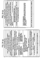
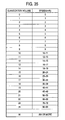
- the speed value is converted to a quantized volume by using the traffic information quantization table shown in Fig. 35.
- the traffic information quantization table in response to the user's request for detailed information of congestion, setting is made so that the quantized volume will increase in steps of 1 km/h in case the speed is less than 10 km/h, 2 km/h in case the speed is within the range of 10 to 19 km/h, 5 km/h in case the speed is within the range of 20 to 49 km/h, and 10 km/h in case the speed is equal to or more than 50 km/h.
- Quantized values obtained using the traffic information quantization table are shown in Fig. 34C.
- the quantized volume is represented by a difference from the statistical prediction value.
- difference between the quantized speed Vn in the target quantization unit and a quantized speed Vn-1 in the upstream quantization unit or statistical prediction value S is calculated by using (Vn - Vn-1). The calculation result is shown in Fig. 34D.
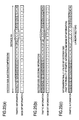
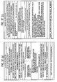
- Variable length encoding is performed on the data thus processed. That is, past traffic information is analyzed and an encoding table for encoding the statistical prediction difference value of traffic information is created, as shown in Fig. 36. By using the encoding table, the value in Fig. 34D is encoded. For example, +2 is encoded to "1111000" while -2 is encoded to "1111001". In case 0 continues, such as 00000, the data is encoded to "100".
- the traffic information thus encoded is, as shown in Figs. 37A and 37B, formed into the data having the data structure of Fig. 37B, together with the shape vector data string information representing a road shape, and is then transmitted.
- a shape vector encoding table, a traffic information quantization table (Fig. 35), and an encoding table of statistical prediction difference values of traffic information (Fig. 36) are transmitted in the same occasion or over a separate route.
- the receiving party which has received the above information decodes the shape vector in each traffic-information-provided section and performs map matching on its own digital map data in order to identify the target road section on its own map and decode the traffic information on this target road section while referencing the encoding table.
- the receiving party can reproduce the traffic information changing along a road (traffic information represented in a function of distance from a reference node).
- the state volume f traffic information changing along a road (Fig. 34B) can be converted to several waveforms having separate frequency components for the receiving party to reproduce the state volume of traffic information even in case the coefficient value of each frequency is provided.
- the conversion to frequency components uses approaches such as FFT (Fast Fourier Transform), DCT (Discrete Cosine Transform), and DWT (Discrete Wavelet Transform).
- FFT Fast Fourier Transform
- DCT Discrete Cosine Transform
- DWT Discrete Wavelet Transform
- the Fourier Transform technique can obtain a Fourier coefficient C(k) from a finite number of discrete values (state volume) represented in a complex function f by way of Expression 1 (Fourier Transform).
- the value obtained through the quantization is obtained as follows: a coefficient of a low frequency is divided by 1; as a coefficient pertains to a higher frequency, a larger value than 1 is used to divide the coefficient by, and the fraction is rounded off.
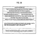
- the quantized value is compressed through variable length compression and is then transmitted. In this case, the data structure of traffic information is as shown in Fig. 38.
- the receiving party which has received the traffic information decodes and dequantizes the coefficient and reproduces the state volume of traffic information by using Expression 2.
- adjusting the value to be divided in quantization obtains a wide range of data from "transmit data with a large volume of information which provides correct reproduction accuracy of traffic information” to "transmit data with a small volume of information which provides lower reproduction accuracy of traffic data”.
- coefficient information is transmitted layer by layer in ascending order of frequency
- the receiving party obtains an outline of the image when it has obtained the information of the coefficient of a lower frequency before obtaining the entire data even when the transmission speed is low.
- the receiving party can determine whether the traffic information is "required or not" and in case not require, skip the information.
- sensors to measure traffic situation ultrasonic vehicle sensors, loop coil sensors, image sensors, etc.
- the user thus has difficulty in correctly evaluating the presented traffic information.
- the user encountering a scene where the provided traffic information is different from the actual situation, may feel an unwanted sense of distrust to the overall traffic information.
- VICS provides "event information” in order to notice an abrupt event. This represents “an accident,” “a construction,” “a control (such as lane control and road closing),” “road abnormalities (road blocking due to cave-in, submersion in water, or collapse of peripheral facilities such as trees and buildings),” and “weather (in particular snowfall and icy road.” A driver who has acquired such information can select another road.
- a large number of related art car navigation units mount a feature to perform path search while considering the added congestion information.
- a service is provided where, in response to information on a start point and a destination transmitted to the center, information on the recommended path from the center which has searched for routes and the destination is received.
- Such path search approaches use a link cost modified based on congestion information to calculate a recommended path. Unknown reliability of the congestion information will make an adverse effect on the result of path search.
- a shortest-time route calculated based on the link cost alone is not necessarily a desirable one to the driver.
- a driver will generally wish to choose a familiar, frequented route provided the route has a small time difference from the shortest-time route.
- the time difference is large, the driver will wish to use the shortest-time route.
- additional information which compares the retrieved route and the familiar route is required.
- the related art path search techniques do not provide such additional information.
- Representation of "an unknown section” may include a method of defining a value as "invalid traffic information.”
- the value of an "unknown” section changes from the value of "invalid traffic information.”
- An example of this is representing a quantized traffic state volume in a difference from the statistical prediction value.
- Vn-1 of the upstream quantization unit is subtracted from the quantization unit value Vn in question to obtain a statistical prediction value S being (Vn - Vn-1)
- the value of the "unknown” section changes from the value of "invalid traffic information.”
- the invention solves the foregoing related art problems and has an object to provide a representation method of representing traffic information and path information together with its reliability and superiority and apparatus and a system which generate, display and utilize the traffic information and path information having such attribute information.
- the invention has another object to provide a traffic information providing system capable of communicating an "unknown" section to a receiving party and a method of representing traffic information, and apparatus constituting the system.
- the invention represents road-related information such as traffic information and path information together with gray scale information which displays the attributes of the information in multiple levels.
- the gray scale information is a representation, in more than one level, of some characteristics of the provided road-related information such as traffic information and path information and some auxiliary information to help the user of the information determine the information more precisely.
- the user can utilize the gray scale information to understand the reliability of the provided road-related information and superiority of the provided path information.
- the invention displays the reliability of the state volume of traffic information in multiple levels by way of the gray scale information.
- the user thus understands how reliable the traffic information is and is able to correctly evaluate the traffic information.
- the invention displays the difference of the state volume of traffic information from that in ordinary traffic by way of the gray scale information.
- the invention displays the change in the state volume of the traffic information in multiple levels by way of the gray scale information.
- the user thus understands whether the congestion is becoming worse or better.
- the invention displays the superiority of a shortest-travel-time path over a reference path in multiple levels.
- the user can make selection: in case a shortest-travel-time path is provided, the user selects the shortest-travel-time path in a higher-superiority section and a familiar, frequented path in a lower-superiority section.
- the invention provides the terminal apparatus with reception means for receiving gray scale information which displays the state volume of traffic information and the attribute of the shortest-time route in multiple levels and display means for displaying the state volume of traffic information in a form corresponding to the value of gray scale information.
- the user thus recognizes the reliability of traffic information and an unpredictable traffic state from the display on the terminal apparatus.
- the invention provides the terminal apparatus with transmission means for transmitting the information on the current location and the destination, reception means for receiving the path information and the gray scale information to displays the superiority of the path information in multiple levels, and display means for displaying the path information in a form corresponding to the value of gray scale information.
- information on the current location and the destination is transmitted and path information is provided.
- the user can determine whether to follow the provided path information based on the superiority of the path information.
- the invention provides the terminal apparatus with reception means for receiving traffic information, route calculation means for calculating a shortest-travel-time path from the current location to the destination while referencing the traffic information, attribute information calculation means for generating the gray scale information to display the superiority of the shortest-travel-time path in multiple levels, and display means for displaying the shortest-travel-time path in a form corresponding to the value of gray scale information.
- the terminal apparatus can receive traffic information and generate the path information to the destination and corresponding gray scale information.
- the invention provides the path information calculation apparatus with dynamic link cost calculation means for calculating the dynamic link cost for a link based on the state volume of traffic information, static link cost calculation means for calculating the static link cost for the link, static link cost provision means for providing the static link cost for the link, and link cost determination means for changing the distribution ratio of the dynamic link cost and static link cost based on the gray scale information which represents the reliability of the superiority of traffic information in multiple levels in order to generate a link cost used for path calculation.
- the path information calculation apparatus can properly set a link cost so that it is possible to perform path search at high accuracy.
- the traffic information providing system of the invention comprises traffic information providing apparatus for retaining, as traffic information, the state volume of traffic information and gray scale information which displays the reliability of the state volume in multiple levels and providing traffic information to which the gray scale information is appended, and client apparatus for receiving the traffic information from the traffic information providing apparatus, in order for the traffic information providing apparatus to set the value of traffic information to be provided to the client apparatus in accordance with the gray scale information appended to the traffic information.
- This system provides a reasonable charging system in which, traffic information with a higher accuracy costs the user a higher change. While traffic information with a lower accuracy costs the user a lower change.
- the traffic information providing system of the invention comprises traffic information providing apparatus for providing, as traffic information, the state volume of traffic information at each of the sampling points set by segmenting a target road and mask bit information indicating that the state volume is valid or invalid, and traffic information utilization apparatus for receiving the traffic information and reproducing the valid state volume by using the mask bit information.
- the receiving party thus correctly identifies the "unknown" section based on the mask bit information.
- the traffic information providing apparatus of the invention comprises a traffic information converter for converting the state volume of traffic information changing along a road to an array of the values of sampling points set by segmenting the target road and generating an array of mask bits representing the validity or invalidity of the values of the sampling points, an encoder for encoding the data generated by the traffic information converter from the state volume of the traffic information and the data of mask bit information, and an information transmitter for transmitting the data encoded by the encoder.
- the traffic information utilization apparatus comprises an information receiver for receiving, from the traffic information providing apparatus, the encoded data concerning the state volume of the traffic information of the target road, the encoded data of mask information representing the validity or invalidity of the state volume, and road section reference data to identify the target road, a decoder for decoding each item of said encoded data and reproducing the valid state volume from the state volume of the traffic information and the mask bit information, and a determination section for performing map matching by using the road section reference data to identify the target road of traffic information.
- the traffic information providing apparatus and the traffic information utilization apparatus may be used to constitute the traffic information providing system of the invention.
- the traffic information display method of the invention sets sampling points by segmenting the target road of traffic information, sets 1 s of mask bit information in correspondence with the sampling points where valid state volumes of traffic information are obtained and sets 0s of mask bit information in correspondence with the sampling points where valid state volumes of traffic information are not obtained, and presents an array of mask bit information together with an array of state volumes of these sampling points.
- the receiving party which has received the traffic information correctly identifies an "unknown" section base on the mask bit information.
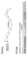
- traffic information such as congestion information, travel time information and speed information is presented in traffic information representing traffic information changing along a road in the state volume of sampling points (state volume of distance quantization unit) (Fig. 1A) and gray scale information representing the reliability of the state volume of each sampling point (Fig. 1B).
- Set interval of said sampling points is not necessarily the same for the state volume of traffic information and gray scale information.
- gray scale information on a single point may be defined for a plurality of sampling points of state volume, or separate number of sampling points may be specified for the state volumes and gray scale information in the same section, without departing from the object of the invention.
- gray scale information is represented in four levels (two bits).
- a state having the highest reliability is represented by 3, followed by 2, 1 as the reliability becomes lower.
- 0 represents a faulty vehicle sensor or an "unknown" state where information is absent.
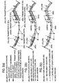
- Figs. 1A through 2C Based on the information, congestion of a road is displayed on the map by using color lines as shown in Figs. 1A through 2C.
- Figs. 1A through 3C a section where the vehicle speed representing the state volume of distance quantization unit is 10 km/h or below appears in red, 10 to 20 km/h in yellow, and 20 km/h or above in green.
- Fig. 2A in case the gray scale information representing the reliability of the state volume is 3, a color transmittance of 0 percent is used. In case the gray scale information is 2, a color transmittance of 33 percent is used. In case the gray scale information is 1, a color transmittance of 66 percent is used.
- congestion is separately displayed for the up line and down line. Color lines to represent congestion are not used in an unknown section.
- a bold line is used.
- a medium bold line is used.
- a fine line is used.
- a solid line is used. In case it is 2, a long dashed line is used. In case it is 1, a short dashed line is used.
- the value of gray scale is higher when the time which has elapsed since collection of information is short (when data is fresh); the value of gray scale information drops as the time which has elapsed becomes longer.
- Fig. 6 shows the configuration of a gray scale information generator 80 for generating gray scale information from the above viewpoints.
- the gray scale information generator 80 comprises: a sensor A traffic determination section 90 for identifying the operation of a sensor A 21 and collecting the information detected by the sensor A 21; a sensor Z traffic determination section 91 for identifying the operation of a sensor Z 22 and collecting the information detected by the sensor Z 22; a probe car traffic determination section 92 for collecting data from a probe car 23 and monitoring the collection state; a traffic information editing section 86 for generating the traffic information at the current point in time; a statistical traffic information database 89 in which past traffic information is accumulated; a statistical traffic information generator 84 for generating statistical traffic information by using the-information accumulated in the statistical traffic information database 89; a prediction information generator 85 for generating traffic prediction information in the near future; a bypath information database 93 in which bypath information is accumulated; a bypath information generator 87 for generating bypath information by using the information accumulated in the bypath information database 93; a probe car measurement information generator 88 for generating probe car measurement information by using the information collected from a probe car 23; a
- the traffic information editing section 86 of the gray scale information generator generates the traffic information at the current point in time by using the information collected by the sensor traffic determination sections 90, 91 and the probe car traffic determination section 92.
- the prediction information generator 85 generates prediction information by using the traffic information at the current point in time generated by the traffic information editing section 86 and the statistical traffic information accumulated in the statistical traffic information database 89.
- the bypath information generator 87 generates the bypath information on a road currently congested by using the information accumulated in the bypath information database 93.
- the statistical traffic information generator 84 statistically analyzes the information accumulated in the statistical traffic information database 89 to generate statistical traffic information.
- the probe car measurement information generator 88 generates probe car measurement information by using the information collected from the probe car 23.
- the traffic information prediction information, statistical traffic information, bypath information and probe car measurement information generated by each section are transmitted to the traffic information accumulating section 81 and the gray scale information calculator 82 and are accumulated in the traffic information accumulating section 81.
- the gray scale information calculator 82 uses the definition table 83 to generate the gray scale information of the above information.
- the gray scale information calculator 82 determines the gray scale value in each section based on the installation density of sensors A to Z and types of the sensors A to Z used by the traffic information editing section 86 to generate traffic information.
- the gray scale information calculator 82 determines the gray scale value in each section based on the time which has elapsed since measurement of data used by the traffic information editing section 86 to generate traffic information.
- the gray scale information calculator 82 determines the gray scale value in each section by calculating the trend of the state volume of traffic information and checking the calculated values against the definition table 83.
- the gray scale information calculator 82 determines the gray scale value in each section by calculating the statistical variations in the state volume of traffic information in the section from the past to present and checking the calculated values against the definition table 83.
- the definition table 83 are defined gray scale values corresponding to the deviations of the state volumes obtained from the measurement values of a sensor from the state volumes obtained from probe information.
- the gray scale information calculator 82 calculates the difference between the state volume of traffic information and the state volume of probe car information and checks the calculated values against the definition table 83 to determine the gray scale value of traffic information in each section.
- the gray scale information calculator 82 calculates the statistical variations in the state volume of statistical traffic information from the past to present and checks the calculated values against the gray scale values corresponding to the statistical variations in the state volume to determine the gray scale value in each section.
- the gray scale information calculator 82 determines the gray scale value in each section based on the calculation system used by the traffic information editing section 86 to generate traffic information.
- the gray scale information calculator 82 calculates the trend of state volume of traffic information and checks the calculated values against the gray scale values corresponding to the variations in the state volume defined in the definition table 83 to determine the gray scale value of state volume of the predicted traffic information generated by the prediction information generator 85.
- the gray scale information calculator 82 calculates the statistical variations in the state volume of traffic information in the section from the past to present and checks the calculated values against the gray scale values corresponding to the statistical variations in the state volume defined in the definition table 83 to determine the gray scale value of state volume of the predicted traffic information generated by the prediction information generator 85.
- the gray scale information calculator 82 calculates the e percentage of correct answers of predicted traffic information generated by the prediction information generator 85 and determines the gray scale value of the predicted traffic information based on the calculated value.
- the gray scale information calculator 82 determines the gray scale value of probe car measurement information based on the number of samples used by the probe car measurement information generator 88 to generate probe car measurement information.
- the gray scale information calculator 82 determines the gray scale value of probe car measurement information based on the time which has elapsed since measurement of probe car data used by the probe car measurement information generator 88 to generate probe car measurement information.
- the gray scale information calculator 82 determines the gray scale value of the bypath information based on the time reduced when a bypath is used in the bypath information generated by the bypath information generator 87.
- the gray scale information generator 80 generates the gray scale information of traffic information, prediction information, statistical traffic information, bypath information and probe car measurement information.
- the gray scale information generator 80 may comprise..only the related blocks.
- Fig. 7 shows a configuration of a path information calculator 100 in car navigation apparatus or path provision apparatus which receives, as traffic information, the state volume of traffic congestion and the gray scale information representing its reliability and outputs path information.
- the path information calculator 100 comprises: a traffic information receiver 101 for receiving traffic information; a dynamic link cost calculator 102 for calculating the dynamic link cost of each link from traffic congestion; a map database 105 for providing map data; a path calculation condition determination section 103 for determining the path calculation condition based on the information input from an external interface; a link cost determination section 104 for determining the link cost of each link by using the gray scale information; a path calculation link cost accumulating section 106 for accumulating the determined link cost; a path calculator 107 for performing path calculation from a beginning to an end by using the accumulated link cost; and a path calculation result transmitter 108 for transmitting the path calculation result as path information.
- the traffic information receiver 101 of the path information calculator 100 receives the state volume of traffic congestion and the gray scale information representing its reliability and outputs the state volume of traffic congestion to the dynamic link cost calculator 102 and a bit string of gray scale to the link cost determination section 104.
- the path calculation condition determination section 103 To the path calculation condition determination section 103 are input, from an external interface (a man-machine interface (path condition setting screen) for car navigation apparatus; a receiver of a path calculation request command for path provision apparatus), the information on the beginning and end of a path to be obtained and the information indicating the conditions for path calculation (such as expressway is given precedence or not, frequency of right/left turn).
- the path calculation condition determination section 103 outputs the information on the beginning and the end to the path calculator 107 and the path calculation condition to the link cost determination section 104.
- the dynamic link cost calculator receiving the information on traffic congestion, calculates the dynamic link cost of each link changing with time which is caused by congestion and outputs the calculated value to the link cost determination section 104.
- the link cost determination section 104 acquires, from the map database (or a path search network) 105, the static link cost of each link not changing with time which is caused by a link length, and changes the distribution ratio of the static link cost to the dynamic link cost by using the gray scale information, thereby calculating the link cost of each link.
- the link cost determination section 104 further changes the link cost to accommodate the path calculation condition, such as weighting an expressway in case an expressway is given precedence.
- the link cost of each link calculated by the link cost determination section 104 is accumulated in the path calculation link cost accumulating section 106.
- the Path calculator 107 acquires a plurality of paths from the beginning to the end from the map database 105. The path calculator 107 then reads the link cost of each route from the path calculation link cost accumulating section 106, calculates the overall link cost of each path from the beginning to the end, and selects a path whose overall link cost is the smallest.
- the Path calculation result transmitter 108 transmits the path information selected by the path calculator 107.
- gray scale information is used as means for measuring the information value of traffic information.
- Fig. 8 shows a system comprising a traffic information transmitter/information charge calculator 120 which provides traffic information on a chargeable basis and client apparatus 130 which receives chargeable traffic information.
- the traffic information transmitter/information charge calculator 120 provides traffic information based on a request by the client apparatus 130.
- the change for the traffic information is calculated based on the gray scale information appended to the traffic information.
- the traffic information transmitter/information charge calculator 120 comprises: a request information receiver 123 for receiving a traffic information request from the client apparatus 130; a traffic information transmission area/target road determination section 122 for determining the area and target road of the traffic information requested by the client apparatus 130, a Traffic information database 121 in which traffic information data with gray scale information appended is accumulated; a traffic information editing section 125 for reading the traffic information on the pertinent area and target road from the traffic information database 121 and editing the read information; a traffic information transmitter 126 for transmitting the edited traffic information to the client apparatus 130; an information charge determination section 124 for determining the charge for the traffic information to provide to the client apparatus 130 based on the gray scale information; and a chare database 127 in which charge data is accumulated.
- the client apparatus 130 comprises: an input operation section 133 to which the user inputs data; an information request area/target road determination section 12 for determining the area and target road of traffic information; a request information transmitter for issuing a request for traffic information to the traffic information transmitter/information charge calculator 120; a traffic information receiver for receiving traffic information from the traffic information transmitter/information charge calculator 120; a decoder 135 for decoding the received traffic information; a traffic information utilization section 136 for utilizing traffic information; and a digital map database 137.
- the traffic information transmitter/information charge calculator 120 of this system accumulate as required the state volume of traffic congestion and the gray scale information indicating its reliability into the traffic information database 121.
- the traffic information transmitter/information charge calculator 120 identifies the area and target road of traffic information requested by the client apparatus 130.
- the traffic information editing section 125 reads the traffic information of the pertinent area from the traffic information database 121.
- the traffic information editing section 125 transmits the traffic information data and the attached gray scale information to the information charge determination section 124 as well as edits the traffic information and provides the edited information to the client terminal 130 via the traffic information transmitter 126.
- the information charge determination section 124 registers thus determined information charge to a charge database 127.
- the client apparatus 130 decodes the traffic information provided by the traffic information transmitter/information charge calculator 120 and uses the decoded information.
- traffic information is represented as the state volume at a sampling point (state volume of distance quantization unit), the invention is also applicable to traffic information otherwise represented.
- a probe car can measure an extremely precise travel time. Thus, it is possible o acquire an alienation volume from the normal traffic fro the traffic information collected using a probe car. It is possible to detect an abrupt congestion from the alienation volume (note that the cause cannot be located).
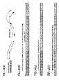
- Fig. 9 shows a graph displaying a measurement time on its horizontal axis and a travel time on its vertical axis, where a transition of travel time in normal traffic is presented in solid lines and transition of travel time in the presence of an abrupt event is presented in dashed lines. When an abrupt event takes place, an unusual increase in travel time is observed.
- the magnitude of alienation of measured travel time data from the past average value of travel time is obtained as attribute information, and the travel time measurement data and gray scale information indicating its attribute information are presented altogether.
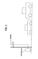
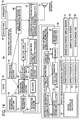
- Fig 10 shows the configuration of a center which generates and provides the measurement information and gray scale information and a receiving party which receives and utilizes this traffic information.
- the center comprises traffic information measurement apparatus 10 for measuring traffic information by using a sensor A (ultrasonic vehicle sensor); a sensor B (image sensor) 22 and a sensor C (probe car) 23, and a traffic information/attribute information generator/transmitter 30 for generating traffic information and gray scale information from measurement information and transmits the resulting information.
- a sensor A ultrasonic vehicle sensor
- sensor B image sensor
- sensor C probe car
- the traffic information measurement apparatus 10 comprises a sensor processor A 11, a sensor processor B 12 and a sensor processor C 13 which process data acquired from the sensors 21, 22, 23, and a traffic information calculator 14 for calculating measurement information of traffic information by using the data processed by the sensor processors 11, 12, 13 and outputting to a traffic information/attribute information generator/transmitter 30 the calculated information together with the information indicating the target section.
- the traffic information/attribute information generator/transmitter 30 comprises: a current traffic information collector 31 for collecting measurement information and target section information from the traffic information measurement apparatus 10; a statistical information accumulating section 32 for accumulating the collected measurement information and target section information; an attribute information generator 37 for calculating the attribute information of the measurement information to generate gray scale information; a traffic information converter 33 for converting the measurement information, gray scale information and target section information to a form suited for encoding; an encoder 34 for encoding the converted data; an information transmitter 35 for transmitting the encoded traffic information, gray scale and target section information; and a digital map database 36 referenced by the traffic information converter 33.
- an information receiver 61 for receiving the information provided by the traffic information transmitter 30
- a decoder 62 for decoding the received
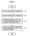
- the attribute information generator 37 of the Traffic information/attribute information generator/transmitter 30 generates gray scale information in accordance with the procedure shown in Fig. 11.
- the attribute information generator 37 acquires the current measurement information collected by the current traffic information collector 31 from the traffic information measurement apparatus 10 (step 1), acquires the past measurement information (statistical information) of the same target section from the statistical information accumulating section 32 (step 2), calculates how far the current measurement information is alienated from the average of statistical information (step 3), and sets a value corresponding to the magnitude of alienation as gray scale information representing the attribute information of the current measurement information (step 4).
- gray scale information For example, in case the attribute information of travel time is displayed in gray scale information of two bits and four levels, a average value and a standard deviation ⁇ are calculated and gray scale information is set as follows in accordance with the magnitude of alienation of the current measurement value from the average value of travel time:
- Fig. 12 schematically shows average values of statistical information of travel time (solid lines), measurement values of travel time on that day (dotted lines) and a range where gray scale information is displayed as 1 (between alternate long and short dashed lines).
- This example shows a case where the gray scale information value exceeds 1 when congestion due to an abrupt event takes place.
- gray scale information can serve as an indicator to identify whether an abrupt congestion (which even the user familiar with the target section cannot predict the flow of cars) is present in the target section.
- the gray scale information is transmitted, while included in traffic information, to the receiving party apparatus 60.
- Figs. 13A and 13B illustrate the data structure of traffic information (Fig. 13B) transmitted from the traffic information/attribute information generator/transmitter 30 and position reference information (Fig. 13A) indicating the target section.
- the traffic information (Fig. 13B) includes the encoded traffic information data and gray scale information data.
- the receiving party apparatus 60 decodes the received data and identifies the target section of traffic information from the position reference information.
- the receiving party apparatus 60 also writes traffic information and gray scale information into the link cost table 66 to update the link cost.
- the information utilization section 67 of the receiving party apparatus 60 blink-displays the congestion information on a map around the local vehicle position while setting a shorter blinking interval as the gray scale information value becomes higher and alienation from the statistical information becomes greater.
- the information utilization section 67 supplies a voice guidance from the guidance apparatus 71 such as "An abrupt congestion is ahead of you (on the route)," in the presence of a congestion with a high gray scale value.
- the information utilization section 67 adds a penalty cost corresponding to the alienation to the standard link cost for a section which has encountered an abrupt congestion in a path search thus making this road section less attractive.
- the driver can avoid a risk of being involved in an unpredictable congestion.
- Traffic provided as traffic information may be a travel time, a travel speed, a traffic volume, an occupancy, a congestion rank, or a congestion length.
- the gray scale information value may be set based on the comparison with the quartiles obtained by splitting the range from the maximum to minimum values in the statistical information. For example, When the current measurement value is equal to or smaller than the first quartile 0 (far less congested than usual) When the current measurement value is between the first and second quartiles 1 (a little less congested than usual) When the current measurement value is between the second and third quartiles 2 (a little more congested than usual) When the current measurement value is equal to or greater than the third quartile 3 (far more congested than usual)
- Statistical information may be summed by day type (weekday, Saturday, Sunday, 5th, 10th, 15th, 20th, 25th and 30th of each month, event day) or by weather and the current measurement value may be compared with the statistical information whose day type or weather are identical with that of the current measurement value.
- gray scale information is meaningful when it is represented in binary notation, "0" indicating an ordinary congestion and "1" indicating an abrupt congestion.
- the target section of traffic information may be identified using information other than a shape vector. For example, a road section identifier, an intersection identifier, a link number, an identifier assigned to each tile-shaped segment of a road map, a kilo post installed at a road, a road name, an address, and a ZIP code may be used as position reference information.
- the receiving party specifies the day type and time zone of the statistical information to be compared with the current information when providing traffic information by using the representation method of the fourth embodiment.
- Traffic on the road recognized by the user may pertain to a specific season, day of week, or a specific weather and may differ from the average traffic congestion on the road. This often happens in case the user drives a car only in a specific season or on a specific day of week. In case the user only drove on the road before a big-scale construction started, the user has no idea about the congestion during a big-scale construction. Congestion and wait time in the parking lot of a large shopping mall, department store, station or indoor amusement facility greatly depend on the weather. The traffic around the parking lots greatly differs between a fine day and a rainy day.
- the system represents the alienation between the traffic of which the user recognizes the congestion and the current traffic in terms of the attribute information of traffic information.
- the user communicates to the information provider the day type, time zone for which the user knows the congestion, or current weather.
- the information provider collects the statistical information satisfying the conditions from the statistical information to generate reference information and compares the reference information with the current information, thereby generating the attribute information of traffic information.
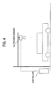
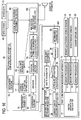
- Fig. 14 shows the configuration of the system.
- the receiving party apparatus 60 comprises: a man-machine interface (MMI) 75 for inputting reference information; a travel locus accumulating section 72 for accumulating a travel locus; a wiper 76 operating in a rainy weather; a reference information determination section 74 for determining the conditions for reference information from the information input from the reference information input MMI 75, the operation of the wiper 76 and past travel locus; and an information transmitter 73 for transmitting the conditions for reference information to the traffic information/attribute information generator/transmitter 30.
- MMI man-machine interface
- a travel locus accumulating section 72 for accumulating a travel locus
- a wiper 76 operating in a rainy weather
- a reference information determination section 74 for determining the conditions for reference information from the information input from the reference information input MMI 75, the operation of the wiper 76 and past travel locus
- an information transmitter 73 for transmitting the conditions for reference information to the traffic information
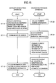
- the flowchart of Fig. 15 shows the operation procedure of the receiving party apparatus 60 and the traffic information/attribute information generator/transmitter 30.
- the reference information determination section 74 of the receiving party apparatus 60 specifies the conditions for reference information based on the information input from the reference information input MMI 75. When the wiper 76 is operating, the reference information determination section 74 specifies a rainy weather as a condition for reference information. From the past travel locus, the reference information determination section 74 obtains the day type and time zone of the past travel history and specifies the day type and time zone as conditions for reference information (step 10). The receiving party apparatus 60 transmits the conditions for reference information to the traffic information/attribute information generator/transmitter 30 (step 11).
- the attribute information generator 37 of the traffic information/attribute information generator/transmitter 30 acquires the current measurement information collected by the current traffic information collector 31 from the traffic information measurement apparatus 10 (step 10), selects the statistical information satisfying the specified conditions to generate reference information (step 21), and compares the current information with the average of reference information to calculate alienation from the average (step 22), sets a value corresponding to the magnitude of alienation as gray scale information, and transmits the current information and the gray scale information to the receiving party apparatus 60 (step 23).
- the receiving party apparatus 60 receives the traffic information and utilizes the information same as in the fourth embodiment (step 12).
- the system provides elaborate traffic information customized to individual experiences of the user.
- the user acquires, as gray scale information, the information compared with the traffic information whose congestion is familiar to the user, thereby correctly predicting the flow of cars in the current congestion.
- appropriate path selection is made possible.
- the increasing/decreasing trend of traffic is determined base on the comparison with the traffic a certain time ago and is represented in gray scale information. For example, to represent an increase/decrease in the travel time, the current travel time is compared with that 30 minutes ago and gray scale information is displayed:
- the user can properly address an abrupt congestion.
- the user may select an alternate route when the travel time is increasing.
- the user may stay in the congestion when the travel time is decreasing.
- the attribute information of traffic information may be variations such as the increasing/decreasing ratio including "increase/decrease in congestion length,” “increase/decrease in travel speed,” “increase/decrease in unit block (or link) travel time” as well as “occupation ratio of a parking lot” and “wait time in a parking lot.”
- Such attribute information may be displayed in gray scale information.
- Car navigation apparatus provides a DRGS (Dynamic Route Guidance System) to present a shortest-time route to the destination.
- DRGS Dynamic Route Guidance System
- a driver may wish to use a familiar, frequented route as long as the time required is almost the same.
- the shortest-time route is compared with another route (reference route) and the superiority of the shortest-time route over the reference route is displayed in gray scale information, and the shortest-time route information and the gray scale information are provided.
- the driver may select the shortest-time route in case its superiority is high and may select another route in case its superiority is low.
- Fig 16 shows the configuration of a system which provides path information by way of this method.
- the center calculates the shortest-time route and the gray scale information and provides the information to the receiving party apparatus, a so-called CDRGS (center-calculation type DRGS).
- CDRGS center-calculation type DRGS
- the route/attribute information calculator/transmitter 300 of the center comprises: a beginning/end determination section for determining the beginning and end of path search based on the information on the current position and the destination transmitted from the receiving party apparatus 60; a current traffic information collector 31 for collecting traffic information and target section information from a traffic information measurement apparatus 10; a route calculator 40 for calculating a shortest-time route to the destination; an attribute information calculator 38 for calculating the superiority of the shortest-time route and generating gray scale information; an encoder 34 for encoding the data on the shortest-time route and gray scale information; an information transmitter 35 for transmitting the encoded route provided and the gray scale information; and a digital map database 36.
- the receiving party apparatus 60 comprises: an information receiver 61 for receiving the information provided by the route/attribute information calculator/transmitter 300; a decoder 62 for decoding the received information to reproduce route information and traffic information; a digital map database 65; a position reference section 63 for referencing the digital map database 65 to identify the provided route; a route information/attribute information utilization section 79 for processing the provided route information and gray scale information and utilizing the processed information; an MMI 180 for displaying the route information; guidance apparatus 71 for performing voice guidance; a local vehicle position determination section 68 for determining the local vehicle position by using a GPS antenna 69 and a gyroscope 70; an MMI 78 for inputting a destination; a current position/destination setting section 77 for setting a current position and a destination; and an information transmitter for transmitting the information on the current position and the destination to the route/attribute information calculator/transmitter 300.
- the flowchart of Fig. 17 shows the operation procedure of the receiving party apparatus 60 and the route/attribute information calculator/transmitter 300.
- a route request screen is displayed on the receiving party apparatus 60, and a destination is input to the screen (step 30).
- the current position/destination setting section 77 acquires the current position (step 30), sets the destination and the current position, and transmits the information to the route/attribute information calculator/transmitter 300 (step 32).
- the current traffic information collector 31 of the route/attribute information calculator/transmitter 300 collects the current (or past as required) from the traffic information measurement apparatus 10 (step 40).
- the route calculator 40 references the collected traffic information and calculates the shortest-time route between the specified current position and destination (step 41).
- the attribute information calculator 38 selects N important intersections on the calculated route (step 42) and determines the reference route of each section split with the beginning, end and important intersections (step 43).
- the route is used as a reference route.
- the shortest-distance route is determined as a reference route.
- the shortest-distance route serves as a shortest-time route, which the driver will usually select.
- Another route for example the Nth route whose travel time between the current position and the destination is Nth shortest may be used as a reference route.
- another representative route whose path matching ratio with the shortest-time route is below a prespecified value may be used as a reference route.
- the attribute information calculator 38 compares the shortest-time route of each section split with the beginning, end and important intersections with the reference route and obtains the superiority of the shortest-time route.
- the attribute information calculator 38 sets the reduced travel time as an indicator of superiority and calculates the superiority in each section while using the correspondence of the travel time reduced by traveling on the shortest-time route instead of the reference route to each superiority:
- the attribute information calculator 38 thus generates gray scale information where the superiority values are arranged.
- the e attribute information calculator 38 then transmits the obtained gray scale information and the information on the shortest-time route to the receiving party apparatus 60 (step 44).
- Figs. 18A and 18B illustrate the data structure of position reference information of route information (Fig. 18A) transmitted from the route/attribute information calculator/transmitter 300 and gray scale information (Fig. 18B) presenting the attribute information of route information.
- the position reference information (Fig. 18A) and the gray scale information (Fig. 18B) may be incorporated as a single data item.
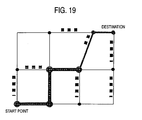
- the receiving party apparatus 60 uses-the position reference information to identify the provided route on a digital map and displays the route on the screen or via voice (step 34).
- the receiving party apparatus 60 changes the thickness of a line representing the provided route depending on the gray scale information value of each section.
- the driver who checks this screen can, for example, determine that the bold line section of the provided route will be followed and the fine line section will be switched to an alternate, frequented route.
- congestion information on each path is displayed in dotted lines.
- the provided route may be displayed, same as display in the first embodiment, (Figs. 2A through 2C), so that the line type (solid line/dashed line) is changed depending on the gray scale values or watermark is changed.
- the system thus sets the superiority of route information over the reference route is to attribute information and provides path information represented in route information and attribute information.
- the driver who has received this information will select the provided shortest-time route (which matches the shortest-distance route in this time zone) in a time zone the road is not congested, such as in the nighttime.
- Evaluation of the superiority of the shortest-time route over the reference route may be made using the procedure of Fig. 20.
- steps up to when the route calculator 40 of the route/attribute information calculator/transmitter 300 calculates the shortest-time route between the specified current position and destination (step 41) are same as Fig. 17.
- the attribute information calculator 38 determines the reference route between the beginning and the end (step 420) and extracts the sections different between both routes and evaluates the superiority of the shortest-time route (step 430). Superiority of the sections where both routes match each other is assumed to be large. For the different section, the superiority is calculated in the same procedure as Fig. 17 and gray scale information where the superiority values are arranged is generated.
- the obtained gray scale information as well as the shortest-time route information are transmitted to the receiving party apparatus 60 (step 440).
- the procedure is employed to reduce the load of superiority calculation.
- the travel tie reduction ratio (%) may be used instead of the reduced travel time.
- superiority is set so that the rate of travel time reduced by traveling on the shortest-time route instead of the reference route will be:
- the probability of reaching the destination earlier by traveling on the shortest-time route instead of the reference route may be set as the superiority indicator.
- Traffic information generally has variations. Considering the variations, the route provided as the shortest-time route is not necessarily the fastest route.
- the winning percentage represents the probability that the provided route will win. When the winning percentage is used as the indicator of superiority, superiority is set as follows:
- Fig. 21 shows the configuration of LDRGS (terminal-calculation DRGS) where the receiving party apparatus which has received traffic information from the center calculates the shortest-time route and gray scale information.
- the traffic information calculator 10 of the center comprises a traffic information transmitter 15 for transmitting information to the receiving party apparatus 60.
- the receiving party apparatus 60 comprises: a traffic information receiver 181 for receiving traffic information; a route calculator 182 for calculating the shortest-time route to the destination; and an attribute information calculator 183 for calculating the superiority of the shortest-time route to generate gray scale information.
- the receiving party apparatus 60 further comprises: a digital map database 65; a route information/attribute information utilization section 79; an MMI section 180; guidance apparatus 71, a GPS antenna 69; a gyroscope 70; a local vehicle position determination section 68; a destination input MMI 78, and a current position/destination setting section 77.
- Fig. 22 shows the operation procedure of the receiving party apparatus 60.
- the operation made by the route calculator and the attribute information calculator of the route/attribute information calculator/transmitter 300 in CDRGS (Fig. 16) is made by the route calculator 182 and the attribute information calculator 183 of the receiving party apparatus 60 inside the receiving party apparatus 60.
- the traffic information providing system of the eighth embodiment of the invention provides the state volume of traffic information changing along a road and mask bit information indicating the validity of the state volume.
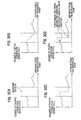
- Mask bit information is, as shown in Figs. 15A through 25C, information which indicates that the state volume of traffic information in the quantization unit (distance quantization unit) obtained by equidistantly segmenting a shape vector (road) is valid or invalid and is represented by 0 or 1, where 0 means that traffic information is invalid and 1 means that traffic information is valid.
- Figs. 25A through 25C show the case where the state volume of the "unknown" section enclosed by an ellipse is set to 0 by the sending party.
- Fig. 25A schematically shows the traffic information and the mask bit information transmitted as encoded/compressed data from the sending party.
- Fig. 25B schematically shows the traffic information and the mask bit information received and decoded by the receiving party. The receiving party finally ANDs the traffic information and the mask bit information to reproduce the traffic information shown in Fig. 25C.
- the state volume of the "unknown" section in the decoded traffic information (Fig. 25B) has changed from 0 through variable-length encoding/compression
- the state volume may be ANDed with the mask bit information in order to clarify the "unknown" section.
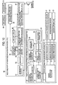
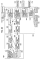
- Fig. 26 shows a traffic information providing system which provides this traffic information.
- the system comprises: traffic information measurement apparatus 1010 for measuring traffic information by using a sensor A (ultrasonic vehicle sensor) 1021, a sensor B (AVI sensor) 1022 and a sensor C (probe car) 1023; an encoding table creating section 1050 for creating an encoding table to encode traffic information; a traffic information transmitter 1030 for encoding and transmitting the traffic information and the information on the target section; and receiving party apparatus 1060 such as car navigation apparatus for receiving the transmitted information.
- a sensor A ultrasonic vehicle sensor
- AVI sensor AVI sensor
- sensor C probe car
- the traffic information measurement apparatus 1010 comprises a sensor processor A 1011, a sensor processor B 1012 and a sensor processor C 1013 for processing the data acquired from the sensors 1021, 1022, 1023; and traffic information calculator 1014 for generating traffic information by using the data processed by the sensor processors 1011, 1012, 1013 and outputting the traffic information and the target section data.
- the encoding table creating section 1050 comprises plural types of traffic information quantization tables used for quantization of traffic information and a distance quantization unit parameter table 1054 for specifying plural types of sampling point intervals (unit block length).
- the encoding table calculator 1051 for creating an encoding table classifies past traffic acquired from the traffic information measurement apparatus 1010 and creates various types of encoding tables 1052 corresponding to all combinations of the traffic information quantization table 1053 and sampling point intervals for all patterns.
- the traffic information transmitter 1030 comprises: a traffic information collector 1031 for collecting traffic information from the traffic information measurement apparatus 1010; a quantization unit determination section 1032 for determining the traffic situation based on the collected traffic information, determining the unit block length of the distance quantization unit, and determining the quantization table and encoding table to be used; traffic information converter 1033 for converting traffic information to a state volume at a sampling point (state volume of distance quantization unit) and generating mask bit information as well as converting the shape vector data in the target section to a statistical prediction difference value; an encoder 1034 for encoding traffic information by using the encoding table 1052 determined by the quantization unit determination section 1032 as well as encoding the shape vector in the target section; an information transmitter 1035 for transmitting the encoded traffic information data and shape vector data; and a digital map database referenced by the traffic information converter 1033.
- the traffic information converter 1033 quantizes the traffic state volume or converts the traffic state volume to a statistical prediction difference value by using the distance quantization unit and the traffic information quantization table 1053 determined by the quantization unit determination section 1032 as well as generates mask bit information where 0 means that the traffic information is invalid and 1 means that the traffic information is valid.
- the encoder 1034 variable-length encodes the statistical prediction difference value of traffic information by using the encoding table 52 determined by the quantization unit determination section 1032 as well as encodes a mask bit string including 0s and 1 s by way of the MH (modified Huffman) encoding system which is a standard encoding system for facsimiles. An example of MH encoding is described below.
- the traffic information converter 1033 converts the traffic state volume to a specific number of state volumes which will allow splitting into frequency components based on the distance quantization unit determined by the quantization unit determination section 1032 a well as generates the mask bit information for the traffic state volume.
- the encoder 1034 splits the traffic state volume into frequency components by using approaches such as FFT, DCT and DWT, quantizes its coefficient based on the quantization table determined by the quantization unit determination section 1032, variable-length encodes the quantized coefficient by using the encoding table determined by the quantization unit determination section 1032, and encodes the mask bit string by using the MH encoding system.
- the receiving party apparatus 1060 comprises: an information receiver for receiving the information provided by the traffic information transmitter 1030; a decoder 1062 for decoding the received information to reproduce the traffic information and shape vector; a map matching and section determination section 1063 for performing map matching of a shape vector by using the data in the digital map database 1065 to determine the target section of traffic information; a traffic information reflecting section 1064 for reflecting the received traffic information into the data for the target section in the link cost table 1066; a local vehicle position determination section 1068 for determining the local vehicle position by using a GPS antenna 1069 and a gyroscope 1070; an information utilization section 1067 for utilizing the link cost table 1066 for route search from the local vehicle position to the destination; and guidance apparatus 1071 for performing voice guidance based on the route search result.
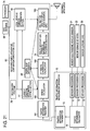
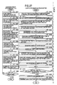
- the flowchart of Fig. 27 shows the operation of each section assumed when the traffic state volume is represented by a difference from the statistical prediction value.
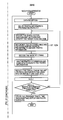
- the encoding table calculator 1051 of the encoding table creating section 1050 analyzes the past traffic information transmitted from the traffic information measurement apparatus 1010 and sums traffic information in the traffic of pattern L (step 1001), sets the quantization unit in the direction of distance (distance quantization unit) M (step 1002), and sets the traffic information quantization table N (step 1003).
- the encoding table calculator 1051 calculates the statistical prediction value S by using the statistical prediction value calculating expression, and calculates the difference between the traffic information state volume and S (statistical prediction difference value) (step 1004).
- the encoding table calculator 1051 calculates the distribution of statistical prediction difference values (step 1005) and calculates the distribution of run lengths (continuous distribution of same value) (step 1006).
- the encoding table calculator 1051 creates an encoding table based on the distribution of statistical prediction difference values and run lengths (step 1007) to complete the encoding table for case L-M-N (step 1008).
- the encoding table calculator 1051 repeats the processing until all cases of L-M-N are complete (step 1009).
- the traffic information transmitter 1030 collects traffic information and determines a traffic-information-provided section (step 1010). Determining that one traffic-information-provided section V is to be addressed (step 1011), the traffic information transmitter 1030 generates a shape vector around the traffic-information-provided section V and sets a reference node (step 1012), then performs irreversible encoding/compression of the shape vector (step 1013). This irreversible encoding/compression method is detailed in Japanese Patent Application No. 2001-134318.
- the quantization unit determination section 1032 determines the traffic situation and determines the sampling interval (unit block- length-of distance quantization unit) and the quantization level (step 1014).
- the traffic information converter 1033 performs sampling in the direction of distance from the reference node of the shape vector by using the determined unit block length and splits the traffic-information-provided section (step 1015), and calculates the state volume of traffic information of each quantization unit (step 1016).
- the traffic information converter 1033 sets mask bit information of 0 to a distance quantization unit whose state volume is invalid and sets mask bit information of 1 to a distance quantization unit whose state volume is valid (step 1017).
- the traffic information converter 1033 performs quantization of traffic information by using the traffic information quantization table 1053 determined by the quantization unit determination section 1032 based on the quantization level (step 1018) and converts the quantized traffic information to a statistical prediction difference value (step 1019).
- the encoder 1034 executes variable length encoding/compression of quantized traffic information by using the encoding table 1052 determined by the quantization unit determination section 1032 (step 1020).
- the encoder 1034 encodes a mask bit information string including 0s and 1 s of each distance quantization unit arranged in the direction of distance from the reference node of the shape vector (for example a mask bit string of 111111111111110000111111 for Fig. 25A) by using the MH encoding system (step 1021).
- the information transmitter 1035 converts the encoded data to transmit data (step 1024) and transmits the data together with the encoding table (step 1025).
- the decoder 1062 decodes the shape vector and the map matching and section determination section 1063 performs map matching on its digital map database 1065 and identifies the target road section (step 1032).
- the decoder 1062 decodes the traffic information state volume of each distance quantization unit by referencing the encoding table (step 1033).
- the decoder 1062 also decodes the mask bit string (step 1034) and validates the traffic information by ANDing the traffic information state volume of each distance quantization unit and the mask bit information.
- the traffic information reflecting section 1064 reflects the decoded travel time in the link cost of the local system (step 1035). This processing is executed for all traffic-information-provided sections (steps 1036, 1037).
- the Information utilization section 1067 utilizes the provided travel time to execute required time display and route guidance (step 1038).
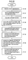
- the flowchart of Fig. 28 shows the operation of each section assumed when the traffic state volume is represented by a coefficient of frequency component.
- the encoding table creating section 1050 executes FFT to obtain an FFT coefficient (step 1204), quantizes the FFT coefficient to calculate a quantization coefficient (step 1205), calculates the distribution of quantization coefficients (step 1207), calculates the distribution of run lengths (step 1207), and creates an encoding table based on them (step 1208).
- the traffic information transmitter 1030 aligns the levels of traffic information set to a real part and an imaginary part (step 1218), executes FFT to transform the data to a Fourier coefficient (step 1219), and performs variable-length encoding/compression on the Fourier coefficient (step 1220).
- the receiving party apparatus references the encoding table and executes inverse Fourier transform to decode traffic information (step 1234).
- Fig. 29 shows an example of data structure of traffic information transmitted together with the shape vector data string information (Fig. 37A) from the traffic information transmitter 30.
- the data includes traffic information converted to the coefficient of frequency component by way of DCT and DWT and variable-length encoded and MH-encoded mask bit information.
- the traffic information transmitter transmits the state volume of the distance quantization unit and mask bit information indicating that the state volume is valid or invalid. This allows the receiving party apparatus to clearly identify a section where the state volume is invalid ("unknown section").
- the receiving party can identify an "unknown” section irrespective of the state volume of the unknown section set by the sending party.
- This allows an arbitrary value of state volume of an "unknown” section to be specified. It is thus preferable to set a value, as a state volume of an "unknown section," so that the state volume of a "valid" section before or after the "unknown” section will not be subject to alteration in the process of encoding and decoding. This is detailed referring to Figs. 30A through 30D.
- the horizontal axis shows a distance from the reference point of the target road section while the vertical axis shows a state volume--such as the speed at that distance.
- a state volume--such as the speed at that distance As shown in Fig. 30A, assume that an "unknown" section whose state volume is invalid exists in the target road section.
- the state volume of the "unknown” section is set to 0 as shown in Figs. 25A through 25C, the state volume at the boundary of the "unknown” section is uniformized when frequency conversion/compression including irreversible encoding and orthogonal conversion is executed, so that the state volume of a "valid" section adjacent to An “unknown” section could significantly change from the original state volume when the state volume is reproduced at the receiving party (Fig. 25B).
- Fig. 30B values before and after an "unknown" section are connected with a straight line and the state volume of the "unknown” section is set to a value on this straight line.
- Fig. 30C state volumes before and after an "unknown” section is also maintained in the “unknown” section and the state volume is switched (both lines are connected) around the center of the "unknown” section.
- Fig. 30D the trend of state volumes before and after an "unknown” section is approximated with a function (a linear function in Fig. 30D but may be another function), and the state volume is switched near the center of the "unknown” section.
- a road section identifier or intersection identifier may be used to identify a road section. For example, concerning two roads which reference the same map, as shown in Fig. 31A, a road section identifier or an intersection identifier may be used to identify a road and specify a reference section based on an absolute position. N sampling points are produced on the pertinent link and the traffic information is represented in traffic information at each sampling point.
- a target road may be identified by using the latitude/longitude data for position reference of the intermittent bodes P1, P1,-P3, P4 extracted from a road in the middle of the link (which data holding the attribute information such as a name and a road type).
- P1 is a link midpoint
- P2 is an intersection
- P3 is a link midpoint
- P4 is a link midpoint.
- the position of each of P1, P2, P3 and P4 is identified, and each section are interconnected through path search to identify the target road.
- Road section reference data to identify a target road may be other than the aforementioned shape vector data string, road section identifier and intersection identifier.
- an identifier assigned to each tile-shaped segment of a road map, a kilo post installed at a road, a road name, an address, and a ZIP code may be used as position reference information to identify a target road section of traffic information.
- a system is described below where a probe car to provide travel data functions as traffic information providing apparatus and a center to collect the information from the probe car functions as traffic information utilization apparatus.
- mask bit information is used to indicate that the measurement information from the probe car is valid or invalid.
- the system comprises a probe-car-mounted machine 1090 for providing travel data and a probe car collection system 1080 for collecting data.
- the probe-car-mounted machine 1090 comprises: an encoding table receiver 1094 for receiving an encoding table used to encode transmit data from the probe car collection system 1080; a sensor information collector 1098 for collecting information detected by a sensor A 1106 for detecting a speed, a sensor B 1107 for detecting power output and a sensor C 1108 for detecting fuel consumption; a sensor V1103 for outputting a door open signal and a sensor Y 1104 for outputting a hazard signal; a measurement information valid/invalid determination section 1097 for determining whether the data collected by a sensor information collector 1098 based on the signal of a sensor Z 1105 for outputting a seta belt signal; a local vehicle position determination section 1093 for determining the local vehicle position by using the information received by a GPS antenna 1101 and information from a gyroscope 1102; a travel locus
- the probe car collection system 1080 comprises: a travel locus receiver 1083 for receiving travel data from the Probe-car-mounted machine 1090; an encoded data decoder 1082 for decoding the received data by using the encoding table data 1086; a travel locus measurement information utilization section 1081 for utilizing the collected travel locus and measurement information; an encoding table selector 1085 for selecting an encoding table to be provided to the probe-car-mounted machine 1090 depending on the current position of the probe car; and an encoding table transmitter 1084 for transmitting the selected encoding table to the probe car.
- the measurement information valid/invalid determination section 1097 of the probe-car-mounted machine 1090 determines whether the measurement values such as the speed information detected by the sensor A 1106, engine load detected by the sensor B 1107, and gasoline consumption detected by the sensor C 1108 are measurement values obtained while the probe car is traveling in a traffic flow, based on the signals transmitted from the sensors X, Y, Z, and stores into the Travel locus measurement information accumulating section 1096 the measurement information from the sensors A, B, C with a flag indicating the determination result attached.
- the measurement information valid/invalid determination section 1097 determines a normal travel, a stop or a short stop by way of hazard lamp on/off.
- the measurement information valid/invalid determination section 1097 detects that the vehicle is not traveling by checking the lamp illumination signal of a parking brake or P position signal of a car with an automatic transmission.
- the measurement information valid/invalid determination section 1097 detects a blinker signal and determines that the vehicle is getting past other vehicles in case it frequently turns on a blinker, for example at least twice within 45 seconds.
- the encoder 1092 creates a mask bit string based on a flag attached by the measurement information valid/invalid determination section 1097 in encoding the travel locus data and measurement information accumulated in the travel locus measurement information accumulating section 1096.
- the travel locus data and measurement information to which this mask bit information attached is transmitted to the probe car collection system 1080.
- Fig. 33 illustrates a data structure of the data transmitted from the probe-car-mounted machine 1090 to the probe car collection system 1080.
- the travel locus measurement information utilization section 1081 of the probe car collection system 1080 determines the validity of information collected by the probe-car-mounted machine 1090 based on the mask bit information attached thereto and determines the traffic volume by using the valid data.
- the invention may be widely used in a center which provides traffic information and path information, a business entity which delivers the provided service, or car-mounted apparatus, a cell phone, a PDC and a PC which displays traffic information and path information.
- the method of representing the road-related information adds attribute information to traffic information and path information, which increases the volume and quality of information and enhances the utility value of information.
- information representing reliability is added to traffic information, the traffic information is properly evaluated.
- the user may flexibly select a path, that is, select a presented path in a section with higher superiority and select a familiar, frequented road in a section with lower superiority.
- the terminal apparatus can display the traffic information and path information in a form easily understood by the user.
- the path information calculator according to the invention can properly set a link cost by using gray scale information, thereby performing a highly accurate path search.
- the traffic information providing system uses gray scale information to employ a reasonable charging system where higher-accuracy traffic information costs the user higher while lower-accuracy traffic information costs the user lower.
- the traffic information providing system provides, as traffic information, the state volume of traffic information changing along a road as well as correctly communicates to the receiving party an "unknown" section whose state volume is not known.
- the method of representing traffic information according to the invention correctly communicates an "unknown" section as well as state volume of traffic information in a valid section adjacent to the "unknown" section.
Landscapes
- Physics & Mathematics (AREA)
- General Physics & Mathematics (AREA)
- Life Sciences & Earth Sciences (AREA)
- Atmospheric Sciences (AREA)
- Traffic Control Systems (AREA)
- Navigation (AREA)
Applications Claiming Priority (7)
| Application Number | Priority Date | Filing Date | Title |
|---|---|---|---|
| JP2002380403 | 2002-12-27 | ||
| JP2002380404 | 2002-12-27 | ||
| JP2002380404 | 2002-12-27 | ||
| JP2002380403A JP2004212143A (ja) | 2002-12-27 | 2002-12-27 | 交通情報提供システム、交通情報表現方法及び装置 |
| JP2003414296 | 2003-12-12 | ||
| JP2003414296A JP2004220574A (ja) | 2002-12-27 | 2003-12-12 | 道路関係情報の表現方法と、それを実施する装置及びシステム |
| PCT/JP2003/017052 WO2004061394A1 (ja) | 2002-12-27 | 2003-12-26 | 交通情報提供システム、交通情報表現方法及び装置 |
Publications (1)
| Publication Number | Publication Date |
|---|---|
| EP1577643A1 true EP1577643A1 (de) | 2005-09-21 |
Family
ID=32718769
Family Applications (1)
| Application Number | Title | Priority Date | Filing Date |
|---|---|---|---|
| EP03786392A Withdrawn EP1577643A1 (de) | 2002-12-27 | 2003-12-26 | Verkehrsinformationsbereitstellungssystem, verkehrsinformationsexpressionsverfahrenund einrichtung |
Country Status (6)
| Country | Link |
|---|---|
| US (1) | US20060082472A1 (de) |
| EP (1) | EP1577643A1 (de) |
| KR (1) | KR20050084501A (de) |
| AU (1) | AU2003296171A1 (de) |
| CA (1) | CA2511878A1 (de) |
| WO (1) | WO2004061394A1 (de) |
Cited By (10)
| Publication number | Priority date | Publication date | Assignee | Title |
|---|---|---|---|---|
| DE102005009604A1 (de) * | 2005-02-28 | 2006-09-14 | Ptv Ag | Verfahren und Vorrichtung zum Erzeugen eines Bewertungswertes für Verkehrsdaten |
| DE102005055244A1 (de) * | 2005-11-19 | 2007-05-31 | Daimlerchrysler Ag | Verfahren zur verkehrsdatenbasierten Unfallerkennung |
| WO2007065756A1 (de) * | 2005-12-06 | 2007-06-14 | Robert Bosch Gmbh | Verfahren und system zur lokalisierung eines streckenabschnittes in einer karte |
| EP1801764A1 (de) * | 2005-12-26 | 2007-06-27 | Aisin Aw Co., Ltd. | Navigationsvorrichtung |
| WO2009036844A1 (en) * | 2007-09-21 | 2009-03-26 | Tomtom International B.V. | Navigation apparatus and method therefor |
| WO2009156188A1 (en) * | 2008-06-25 | 2009-12-30 | Tomtom International B.V. | Navigation device & method |
| US8306556B2 (en) * | 2006-02-08 | 2012-11-06 | Telenav, Inc. | Intelligent real-time distributed traffic sampling and navigation system |
| WO2015047080A1 (en) * | 2013-09-24 | 2015-04-02 | Data Mining Innovators B.V. | A geographic based location system arranged for providing, via a web-based portal, management information of geographic data and non-geographic data generated by a plurality of wireless communication devices, and a related method |
| CN107179088A (zh) * | 2017-04-14 | 2017-09-19 | 深圳市国科微半导体股份有限公司 | 一种基于高架路面的车辆导航方法及其装置 |
| CN112702721A (zh) * | 2015-04-10 | 2021-04-23 | 松下电器(美国)知识产权公司 | 控制接收或发送系统信息的装置的处理的集成电路 |
Families Citing this family (68)
| Publication number | Priority date | Publication date | Assignee | Title |
|---|---|---|---|---|
| US6693557B2 (en) | 2001-09-27 | 2004-02-17 | Wavetronix Llc | Vehicular traffic sensor |
| US7480512B2 (en) * | 2004-01-16 | 2009-01-20 | Bones In Motion, Inc. | Wireless device, program products and methods of using a wireless device to deliver services |
| US7805149B2 (en) * | 2004-01-16 | 2010-09-28 | Adidas Ag | Location-aware fitness training device, methods, and program products that support real-time interactive communication and automated route generation |
| JP2005199875A (ja) * | 2004-01-16 | 2005-07-28 | Nippon Seiki Co Ltd | 車両用情報提供装置 |
| JP4393222B2 (ja) * | 2004-02-25 | 2010-01-06 | 株式会社日立製作所 | 交通情報表示装置 |
| JP4442266B2 (ja) * | 2004-03-16 | 2010-03-31 | マックス株式会社 | リングバインダー用のバックプレート並びにファイルカバー |
| EP1734492B1 (de) * | 2004-03-29 | 2012-10-03 | Pioneer Corporation | Karteninformationsanzeige-steuereinrichtung, system, verfahren und programm und aufzeichnungsmedium, auf dem das programm aufgezeichnet ist |
| JP4396380B2 (ja) * | 2004-04-26 | 2010-01-13 | アイシン・エィ・ダブリュ株式会社 | 交通情報の送信装置及び送信方法 |
| US12105208B2 (en) | 2004-06-30 | 2024-10-01 | Adidas Ag | Systems and methods for providing a health coaching message |
| US7797100B2 (en) * | 2004-09-24 | 2010-09-14 | Aisin Aw Co., Ltd. | Navigation systems, methods, and programs |
| US7751589B2 (en) * | 2005-04-18 | 2010-07-06 | Intel Corporation | Three-dimensional road map estimation from video sequences by tracking pedestrians |
| TWI258719B (en) * | 2005-05-02 | 2006-07-21 | Mitac Int Corp | Driving route planning system and method |
| US7698061B2 (en) | 2005-09-23 | 2010-04-13 | Scenera Technologies, Llc | System and method for selecting and presenting a route to a user |
| US8665113B2 (en) | 2005-10-31 | 2014-03-04 | Wavetronix Llc | Detecting roadway targets across beams including filtering computed positions |
| US7899611B2 (en) * | 2006-03-03 | 2011-03-01 | Inrix, Inc. | Detecting anomalous road traffic conditions |
| US20070208498A1 (en) * | 2006-03-03 | 2007-09-06 | Inrix, Inc. | Displaying road traffic condition information and user controls |
| US8700296B2 (en) | 2006-03-03 | 2014-04-15 | Inrix, Inc. | Dynamic prediction of road traffic conditions |
| US7912628B2 (en) | 2006-03-03 | 2011-03-22 | Inrix, Inc. | Determining road traffic conditions using data from multiple data sources |
| US7203595B1 (en) * | 2006-03-15 | 2007-04-10 | Traffic.Com, Inc. | Rating that represents the status along a specified driving route |
| US7702456B2 (en) * | 2006-04-14 | 2010-04-20 | Scenera Technologies, Llc | System and method for presenting a computed route |
| US7617042B2 (en) * | 2006-06-30 | 2009-11-10 | Microsoft Corporation | Computing and harnessing inferences about the timing, duration, and nature of motion and cessation of motion with applications to mobile computing and communications |
| US20080262710A1 (en) * | 2007-04-23 | 2008-10-23 | Jing Li | Method and system for a traffic management system based on multiple classes |
| JP5045210B2 (ja) * | 2007-04-25 | 2012-10-10 | 株式会社デンソー | 走行情報収集装置 |
| JP4555321B2 (ja) * | 2007-07-25 | 2010-09-29 | クラリオン株式会社 | 経路探索装置、およびその経路探索方法 |
| US8221290B2 (en) | 2007-08-17 | 2012-07-17 | Adidas International Marketing B.V. | Sports electronic training system with electronic gaming features, and applications thereof |
| US8702430B2 (en) | 2007-08-17 | 2014-04-22 | Adidas International Marketing B.V. | Sports electronic training system, and applications thereof |
| US8360904B2 (en) | 2007-08-17 | 2013-01-29 | Adidas International Marketing Bv | Sports electronic training system with sport ball, and applications thereof |
| US8164488B2 (en) * | 2008-01-22 | 2012-04-24 | Cisco Technology, Inc. | Apparatus and method for generating a message based on traffic flow |
| EP2104081A1 (de) * | 2008-03-19 | 2009-09-23 | Harman Becker Automotive Systems GmbH | Verfahren zur Bereitstellung eines Verkehrsmusters für Navigationskartendaten und Navigationskartendaten |
| DE102008021260A1 (de) * | 2008-04-29 | 2009-11-05 | Bayerische Motoren Werke Aktiengesellschaft | Verfahren zur Güteprüfung von Verkehrsstörungsmeldeverfahren |
| US9409052B2 (en) * | 2008-10-03 | 2016-08-09 | Adidas Ag | Program products, methods, and systems for providing location-aware fitness monitoring services |
| GR1006698B (el) * | 2008-12-22 | 2010-02-05 | Μεθοδολογια και συστημα για συλλογη, επεξεργασια και διανομη δεδομενων οδικης κινησης για βελτιωμενη δρομολογηση σε συστηματα δορυφορικης πλοηγησης οχηματων | |
| US8068016B2 (en) * | 2009-02-04 | 2011-11-29 | Mitsubishi Electric Research Laboratories, Inc. | Method and system for disseminating witness information in multi-hop broadcast network |
| US20120047087A1 (en) | 2009-03-25 | 2012-02-23 | Waldeck Technology Llc | Smart encounters |
| US20110184642A1 (en) * | 2009-12-18 | 2011-07-28 | Daimler Trucks North America Llc | Fuel efficient routing system and method |
| US10039970B2 (en) | 2010-07-14 | 2018-08-07 | Adidas Ag | Location-aware fitness monitoring methods, systems, and program products, and applications thereof |
| US9392941B2 (en) | 2010-07-14 | 2016-07-19 | Adidas Ag | Fitness monitoring methods, systems, and program products, and applications thereof |
| US8650193B1 (en) * | 2010-07-23 | 2014-02-11 | Google Inc. | Road splitting in a map editor |
| JP5083388B2 (ja) * | 2010-07-29 | 2012-11-28 | トヨタ自動車株式会社 | 交通制御システムおよび交通管制システム |
| JP4978720B2 (ja) * | 2010-08-06 | 2012-07-18 | トヨタ自動車株式会社 | 区間定義方法、及び旅行時間演算装置、及び運転支援装置 |
| CN102081843B (zh) * | 2010-12-17 | 2014-03-12 | 合肥工业大学 | 用于道路安全监控的集成信息系统及监控方法 |
| US20120202525A1 (en) * | 2011-02-08 | 2012-08-09 | Nokia Corporation | Method and apparatus for distributing and displaying map events |
| US20120258433A1 (en) | 2011-04-05 | 2012-10-11 | Adidas Ag | Fitness Monitoring Methods, Systems, And Program Products, And Applications Thereof |
| US8704682B1 (en) * | 2011-06-29 | 2014-04-22 | Google Inc. | Object detection to determine road priority |
| JP5683722B2 (ja) * | 2011-12-28 | 2015-03-11 | 三菱電機株式会社 | センター側システム及び車両側システム |
| DE102012204306A1 (de) * | 2012-03-19 | 2013-09-19 | Bayerische Motoren Werke Aktiengesellschaft | Verfahren zur Steuerung eines Bereitstellens von Verkehrsinformationsdaten zur Aktualisierung einer Verkehrsinformation |
| DE102012212740A1 (de) * | 2012-07-19 | 2014-05-22 | Continental Automotive Gmbh | System und Verfahren zum Aktualisieren einer digitalen Karte eines Fahrerassistenzsystems |
| US20140075348A1 (en) * | 2012-09-11 | 2014-03-13 | Nokia Corporation | Method and apparatus for associating event types with place types |
| CN102881182B (zh) * | 2012-11-01 | 2016-01-13 | 深圳市凯立德科技股份有限公司 | 一种交通信息显示方法及其装置 |
| JP6071467B2 (ja) * | 2012-11-22 | 2017-02-01 | 三菱重工メカトロシステムズ株式会社 | 交通情報処理システム、サーバ装置、交通情報処理方法、及びプログラム |
| US9412271B2 (en) * | 2013-01-30 | 2016-08-09 | Wavetronix Llc | Traffic flow through an intersection by reducing platoon interference |
| US9129522B2 (en) * | 2013-07-01 | 2015-09-08 | Iteris, Inc. | Traffic speed estimation using temporal and spatial smoothing of GPS speed data |
| CN104603821B (zh) * | 2013-08-30 | 2016-10-19 | 株式会社小松制作所 | 矿山机械的管理系统以及矿山机械的管理方法 |
| US9613529B2 (en) * | 2014-02-03 | 2017-04-04 | Here Global B.V. | Predictive incident aggregation |
| JP5662614B1 (ja) * | 2014-06-19 | 2015-02-04 | 浩 鎌田 | 客動線作成システム |
| JP6322523B2 (ja) | 2014-09-03 | 2018-05-09 | アイシン・エィ・ダブリュ株式会社 | 経路探索システム、経路探索方法及びコンピュータプログラム |
| US10320913B2 (en) * | 2014-12-05 | 2019-06-11 | Microsoft Technology Licensing, Llc | Service content tailored to out of routine events |
| US11313692B2 (en) * | 2015-09-01 | 2022-04-26 | Honda Motor Co., Ltd. | Navigation server and navigation system |
| DE112016004370B4 (de) * | 2015-10-16 | 2025-03-06 | Hitachi Astemo, Ltd. | Fahrzeugsteuerung und Fahrzeugsteuervorrichtung |
| JP6472374B2 (ja) * | 2015-12-22 | 2019-02-20 | 本田技研工業株式会社 | ナビサーバおよびナビシステム |
| US10769946B1 (en) * | 2017-04-24 | 2020-09-08 | Ronald M Harstad | Incentive-compatible, asymmetric-information, real-time traffic-routing differential-advice |
| US10679312B2 (en) * | 2017-04-25 | 2020-06-09 | Lyft Inc. | Dynamic autonomous vehicle servicing and management |
| US11183061B2 (en) | 2018-01-30 | 2021-11-23 | Toyota Research Institute, Inc. | Parking monitoring for wait time prediction |
| US11040246B2 (en) | 2018-02-06 | 2021-06-22 | Adidas Ag | Increasing accuracy in workout autodetection systems and methods |
| GB201918833D0 (en) * | 2019-12-19 | 2020-02-05 | Tomtom Traffic Bv | Methods and systems for generating traffic volume data |
| CN111650626B (zh) * | 2020-06-01 | 2021-08-06 | 知行汽车科技(苏州)有限公司 | 道路信息获取方法、装置及存储介质 |
| KR20240100682A (ko) * | 2022-12-23 | 2024-07-02 | 현대오토에버 주식회사 | 전체경로 기반 최적경로 탐색 장치 및 방법 |
| CN119399479B (zh) * | 2025-01-06 | 2025-05-13 | 杭州电子科技大学 | 一种基于图像的车辆淹没部位自动判别方法 |
Family Cites Families (11)
| Publication number | Priority date | Publication date | Assignee | Title |
|---|---|---|---|---|
| JPH09138134A (ja) * | 1995-11-14 | 1997-05-27 | Nissan Motor Co Ltd | 車両用経路誘導装置 |
| JPH09245292A (ja) * | 1996-03-11 | 1997-09-19 | Yazaki Corp | 車載ナビゲーション装置 |
| JP3480242B2 (ja) * | 1996-11-29 | 2003-12-15 | トヨタ自動車株式会社 | 動的経路案内装置 |
| JP3466413B2 (ja) * | 1997-04-04 | 2003-11-10 | トヨタ自動車株式会社 | 経路探索装置 |
| JPH11184373A (ja) * | 1997-12-24 | 1999-07-09 | Hitachi Ltd | 地図受信表示装置 |
| JP2000182180A (ja) * | 1998-12-16 | 2000-06-30 | Sumitomo Electric Ind Ltd | 車両監視システム,車両監視端末装置及び車両監視中央装置 |
| IL131700A0 (en) * | 1999-03-08 | 2001-03-19 | Mintz Yosef | Method and system for mapping traffic congestion |
| JP2002042293A (ja) * | 2000-07-27 | 2002-02-08 | Toshiba Corp | 交通情報提供システム |
| JP4348503B2 (ja) * | 2000-12-21 | 2009-10-21 | 三菱電機株式会社 | ナビゲーション装置 |
| JP3753014B2 (ja) * | 2001-05-11 | 2006-03-08 | 住友電気工業株式会社 | 交通流の異常検知装置及び方法 |
| JP2002350169A (ja) * | 2001-05-30 | 2002-12-04 | Alpine Electronics Inc | ナビゲーション装置 |
-
2003
- 2003-12-26 KR KR1020057012163A patent/KR20050084501A/ko not_active Withdrawn
- 2003-12-26 AU AU2003296171A patent/AU2003296171A1/en not_active Abandoned
- 2003-12-26 US US10/541,042 patent/US20060082472A1/en not_active Abandoned
- 2003-12-26 WO PCT/JP2003/017052 patent/WO2004061394A1/ja not_active Ceased
- 2003-12-26 CA CA002511878A patent/CA2511878A1/en not_active Abandoned
- 2003-12-26 EP EP03786392A patent/EP1577643A1/de not_active Withdrawn
Non-Patent Citations (1)
| Title |
|---|
| See references of WO2004061394A1 * |
Cited By (15)
| Publication number | Priority date | Publication date | Assignee | Title |
|---|---|---|---|---|
| DE102005009604B4 (de) * | 2005-02-28 | 2008-07-17 | Ptv Ag | Verfahren und Vorrichtung zum Erzeugen eines Bewertungswertes für Verkehrsdaten |
| DE102005009604A1 (de) * | 2005-02-28 | 2006-09-14 | Ptv Ag | Verfahren und Vorrichtung zum Erzeugen eines Bewertungswertes für Verkehrsdaten |
| DE102005055244A1 (de) * | 2005-11-19 | 2007-05-31 | Daimlerchrysler Ag | Verfahren zur verkehrsdatenbasierten Unfallerkennung |
| WO2007065756A1 (de) * | 2005-12-06 | 2007-06-14 | Robert Bosch Gmbh | Verfahren und system zur lokalisierung eines streckenabschnittes in einer karte |
| US7706966B2 (en) | 2005-12-26 | 2010-04-27 | Aisin Aw Co., Ltd. | Navigation systems, methods, and programs |
| EP1801764A1 (de) * | 2005-12-26 | 2007-06-27 | Aisin Aw Co., Ltd. | Navigationsvorrichtung |
| US8306556B2 (en) * | 2006-02-08 | 2012-11-06 | Telenav, Inc. | Intelligent real-time distributed traffic sampling and navigation system |
| WO2009036844A1 (en) * | 2007-09-21 | 2009-03-26 | Tomtom International B.V. | Navigation apparatus and method therefor |
| WO2009156187A1 (en) * | 2008-06-25 | 2009-12-30 | Tomtom International B.V. | Navigation device & method |
| WO2009156188A1 (en) * | 2008-06-25 | 2009-12-30 | Tomtom International B.V. | Navigation device & method |
| WO2015047080A1 (en) * | 2013-09-24 | 2015-04-02 | Data Mining Innovators B.V. | A geographic based location system arranged for providing, via a web-based portal, management information of geographic data and non-geographic data generated by a plurality of wireless communication devices, and a related method |
| CN112702721A (zh) * | 2015-04-10 | 2021-04-23 | 松下电器(美国)知识产权公司 | 控制接收或发送系统信息的装置的处理的集成电路 |
| CN112702721B (zh) * | 2015-04-10 | 2024-03-08 | 松下电器(美国)知识产权公司 | 控制接收或发送系统信息的装置的处理的集成电路 |
| CN107179088A (zh) * | 2017-04-14 | 2017-09-19 | 深圳市国科微半导体股份有限公司 | 一种基于高架路面的车辆导航方法及其装置 |
| CN107179088B (zh) * | 2017-04-14 | 2020-05-22 | 深圳市森国科科技股份有限公司 | 一种基于高架路面的车辆导航方法及其装置 |
Also Published As
| Publication number | Publication date |
|---|---|
| AU2003296171A1 (en) | 2004-07-29 |
| CA2511878A1 (en) | 2004-07-22 |
| WO2004061394A1 (ja) | 2004-07-22 |
| US20060082472A1 (en) | 2006-04-20 |
| KR20050084501A (ko) | 2005-08-26 |
Similar Documents
| Publication | Publication Date | Title |
|---|---|---|
| EP1577643A1 (de) | Verkehrsinformationsbereitstellungssystem, verkehrsinformationsexpressionsverfahrenund einrichtung | |
| US7747381B2 (en) | Road information provision system, road information provision apparatus, and road information generation method | |
| US7706964B2 (en) | Inferring road speeds for context-sensitive routing | |
| US7610151B2 (en) | Collaborative route planning for generating personalized and context-sensitive routing recommendations | |
| JP2004220574A (ja) | 道路関係情報の表現方法と、それを実施する装置及びシステム | |
| US20150149070A1 (en) | System for providing traffic information | |
| JP2004234649A (ja) | ナビサーバ,ナビゲーションの表示方法 | |
| US6329932B1 (en) | Method for determining traffic data and traffic information exchange | |
| JP4233364B2 (ja) | 交通情報送信方法、交通情報送信システム及び装置 | |
| JP2021182332A (ja) | 渋滞予測情報提供システム、渋滞予測情報提供方法および渋滞予測情報提供プログラム | |
| KR100820467B1 (ko) | 도로 차선 종류를 고려한 구간 교통량 예측 시스템 및 그방법 | |
| JP4619682B2 (ja) | 交通情報の生成方法と装置 | |
| JP4212536B2 (ja) | 道路情報提供システム及び装置と道路情報生成方法 | |
| JP2003203243A (ja) | 地図データの蓄積及び送信方法とそれを実施する装置 | |
| KR100313456B1 (ko) | 자동차교통정보제공시스템 | |
| JP2004212143A (ja) | 交通情報提供システム、交通情報表現方法及び装置 | |
| JP3748420B2 (ja) | ビーコンを用いたfcdシステムと装置 | |
| JP2004342138A (ja) | ビーコンを用いたfcdシステムと装置 | |
| JP3355887B2 (ja) | 旅行時間予測方法および旅行時間予測装置 | |
| JP2003228788A (ja) | 移動情報分類装置、移動情報分類方法、及び移動情報分類プログラム | |
| JP2002260142A (ja) | 走行時間予測方法 | |
| CN115707610A (zh) | 选择用于记录载具的路线的方法 | |
| JP2001093078A (ja) | 混雑状況表示システム | |
| Oh | Modeling loop detector location for traffic data collection on urban arterials for advanced traveler information system (ATIS) application |
Legal Events
| Date | Code | Title | Description |
|---|---|---|---|
| PUAI | Public reference made under article 153(3) epc to a published international application that has entered the european phase |
Free format text: ORIGINAL CODE: 0009012 |
|
| 17P | Request for examination filed |
Effective date: 20050627 |
|
| AK | Designated contracting states |
Kind code of ref document: A1 Designated state(s): AT BE BG CH CY CZ DE DK EE ES FI FR GB GR HU IE IT LI LU MC NL PT RO SE SI SK TR |
|
| AX | Request for extension of the european patent |
Extension state: AL LT LV MK |
|
| DAX | Request for extension of the european patent (deleted) | ||
| RBV | Designated contracting states (corrected) |
Designated state(s): DE FR GB |
|
| RAP1 | Party data changed (applicant data changed or rights of an application transferred) |
Owner name: PANASONIC CORPORATION |
|
| STAA | Information on the status of an ep patent application or granted ep patent |
Free format text: STATUS: THE APPLICATION IS DEEMED TO BE WITHDRAWN |
|
| 18D | Application deemed to be withdrawn |
Effective date: 20100105 |