EP1577557A2 - Compresseur multi-cylindres à pistons rotatifs et système de compression et unité de réfrigération le comprenant - Google Patents
Compresseur multi-cylindres à pistons rotatifs et système de compression et unité de réfrigération le comprenant Download PDFInfo
- Publication number
- EP1577557A2 EP1577557A2 EP05005174A EP05005174A EP1577557A2 EP 1577557 A2 EP1577557 A2 EP 1577557A2 EP 05005174 A EP05005174 A EP 05005174A EP 05005174 A EP05005174 A EP 05005174A EP 1577557 A2 EP1577557 A2 EP 1577557A2
- Authority
- EP
- European Patent Office
- Prior art keywords
- rotary
- rotary compressing
- vane
- compressing
- refrigerant
- Prior art date
- Legal status (The legal status is an assumption and is not a legal conclusion. Google has not performed a legal analysis and makes no representation as to the accuracy of the status listed.)
- Granted
Links
Images


Classifications
-
- F—MECHANICAL ENGINEERING; LIGHTING; HEATING; WEAPONS; BLASTING
- F04—POSITIVE - DISPLACEMENT MACHINES FOR LIQUIDS; PUMPS FOR LIQUIDS OR ELASTIC FLUIDS
- F04C—ROTARY-PISTON, OR OSCILLATING-PISTON, POSITIVE-DISPLACEMENT MACHINES FOR LIQUIDS; ROTARY-PISTON, OR OSCILLATING-PISTON, POSITIVE-DISPLACEMENT PUMPS
- F04C23/00—Combinations of two or more pumps, each being of rotary-piston or oscillating-piston type, specially adapted for elastic fluids; Pumping installations specially adapted for elastic fluids; Multi-stage pumps specially adapted for elastic fluids
- F04C23/001—Combinations of two or more pumps, each being of rotary-piston or oscillating-piston type, specially adapted for elastic fluids; Pumping installations specially adapted for elastic fluids; Multi-stage pumps specially adapted for elastic fluids of similar working principle
-
- F—MECHANICAL ENGINEERING; LIGHTING; HEATING; WEAPONS; BLASTING
- F01—MACHINES OR ENGINES IN GENERAL; ENGINE PLANTS IN GENERAL; STEAM ENGINES
- F01C—ROTARY-PISTON OR OSCILLATING-PISTON MACHINES OR ENGINES
- F01C21/00—Component parts, details or accessories not provided for in groups F01C1/00 - F01C20/00
- F01C21/08—Rotary pistons
- F01C21/0809—Construction of vanes or vane holders
- F01C21/0818—Vane tracking; control therefor
- F01C21/0827—Vane tracking; control therefor by mechanical means
- F01C21/0845—Vane tracking; control therefor by mechanical means comprising elastic means, e.g. springs
-
- F—MECHANICAL ENGINEERING; LIGHTING; HEATING; WEAPONS; BLASTING
- F01—MACHINES OR ENGINES IN GENERAL; ENGINE PLANTS IN GENERAL; STEAM ENGINES
- F01C—ROTARY-PISTON OR OSCILLATING-PISTON MACHINES OR ENGINES
- F01C21/00—Component parts, details or accessories not provided for in groups F01C1/00 - F01C20/00
- F01C21/08—Rotary pistons
- F01C21/0809—Construction of vanes or vane holders
- F01C21/0818—Vane tracking; control therefor
- F01C21/0854—Vane tracking; control therefor by fluid means
- F01C21/0863—Vane tracking; control therefor by fluid means the fluid being the working fluid
-
- F—MECHANICAL ENGINEERING; LIGHTING; HEATING; WEAPONS; BLASTING
- F04—POSITIVE - DISPLACEMENT MACHINES FOR LIQUIDS; PUMPS FOR LIQUIDS OR ELASTIC FLUIDS
- F04C—ROTARY-PISTON, OR OSCILLATING-PISTON, POSITIVE-DISPLACEMENT MACHINES FOR LIQUIDS; ROTARY-PISTON, OR OSCILLATING-PISTON, POSITIVE-DISPLACEMENT PUMPS
- F04C18/00—Rotary-piston pumps specially adapted for elastic fluids
- F04C18/30—Rotary-piston pumps specially adapted for elastic fluids having the characteristics covered by two or more of groups F04C18/02, F04C18/08, F04C18/22, F04C18/24, F04C18/48, or having the characteristics covered by one of these groups together with some other type of movement between co-operating members
- F04C18/34—Rotary-piston pumps specially adapted for elastic fluids having the characteristics covered by two or more of groups F04C18/02, F04C18/08, F04C18/22, F04C18/24, F04C18/48, or having the characteristics covered by one of these groups together with some other type of movement between co-operating members having the movement defined in group F04C18/08 or F04C18/22 and relative reciprocation between the co-operating members
- F04C18/356—Rotary-piston pumps specially adapted for elastic fluids having the characteristics covered by two or more of groups F04C18/02, F04C18/08, F04C18/22, F04C18/24, F04C18/48, or having the characteristics covered by one of these groups together with some other type of movement between co-operating members having the movement defined in group F04C18/08 or F04C18/22 and relative reciprocation between the co-operating members with vanes reciprocating with respect to the outer member
- F04C18/3562—Rotary-piston pumps specially adapted for elastic fluids having the characteristics covered by two or more of groups F04C18/02, F04C18/08, F04C18/22, F04C18/24, F04C18/48, or having the characteristics covered by one of these groups together with some other type of movement between co-operating members having the movement defined in group F04C18/08 or F04C18/22 and relative reciprocation between the co-operating members with vanes reciprocating with respect to the outer member the inner and outer member being in contact along one line or continuous surfaces substantially parallel to the axis of rotation
- F04C18/3564—Rotary-piston pumps specially adapted for elastic fluids having the characteristics covered by two or more of groups F04C18/02, F04C18/08, F04C18/22, F04C18/24, F04C18/48, or having the characteristics covered by one of these groups together with some other type of movement between co-operating members having the movement defined in group F04C18/08 or F04C18/22 and relative reciprocation between the co-operating members with vanes reciprocating with respect to the outer member the inner and outer member being in contact along one line or continuous surfaces substantially parallel to the axis of rotation the surfaces of the inner and outer member, forming the working space, being surfaces of revolution
-
- F—MECHANICAL ENGINEERING; LIGHTING; HEATING; WEAPONS; BLASTING
- F04—POSITIVE - DISPLACEMENT MACHINES FOR LIQUIDS; PUMPS FOR LIQUIDS OR ELASTIC FLUIDS
- F04C—ROTARY-PISTON, OR OSCILLATING-PISTON, POSITIVE-DISPLACEMENT MACHINES FOR LIQUIDS; ROTARY-PISTON, OR OSCILLATING-PISTON, POSITIVE-DISPLACEMENT PUMPS
- F04C28/00—Control of, monitoring of, or safety arrangements for, pumps or pumping installations specially adapted for elastic fluids
- F04C28/08—Control of, monitoring of, or safety arrangements for, pumps or pumping installations specially adapted for elastic fluids characterised by varying the rotational speed
-
- F—MECHANICAL ENGINEERING; LIGHTING; HEATING; WEAPONS; BLASTING
- F04—POSITIVE - DISPLACEMENT MACHINES FOR LIQUIDS; PUMPS FOR LIQUIDS OR ELASTIC FLUIDS
- F04C—ROTARY-PISTON, OR OSCILLATING-PISTON, POSITIVE-DISPLACEMENT MACHINES FOR LIQUIDS; ROTARY-PISTON, OR OSCILLATING-PISTON, POSITIVE-DISPLACEMENT PUMPS
- F04C29/00—Component parts, details or accessories of pumps or pumping installations, not provided for in groups F04C18/00 - F04C28/00
-
- F—MECHANICAL ENGINEERING; LIGHTING; HEATING; WEAPONS; BLASTING
- F04—POSITIVE - DISPLACEMENT MACHINES FOR LIQUIDS; PUMPS FOR LIQUIDS OR ELASTIC FLUIDS
- F04C—ROTARY-PISTON, OR OSCILLATING-PISTON, POSITIVE-DISPLACEMENT MACHINES FOR LIQUIDS; ROTARY-PISTON, OR OSCILLATING-PISTON, POSITIVE-DISPLACEMENT PUMPS
- F04C2270/00—Control; Monitoring or safety arrangements
- F04C2270/56—Number of pump/machine units in operation
-
- F—MECHANICAL ENGINEERING; LIGHTING; HEATING; WEAPONS; BLASTING
- F04—POSITIVE - DISPLACEMENT MACHINES FOR LIQUIDS; PUMPS FOR LIQUIDS OR ELASTIC FLUIDS
- F04C—ROTARY-PISTON, OR OSCILLATING-PISTON, POSITIVE-DISPLACEMENT MACHINES FOR LIQUIDS; ROTARY-PISTON, OR OSCILLATING-PISTON, POSITIVE-DISPLACEMENT PUMPS
- F04C23/00—Combinations of two or more pumps, each being of rotary-piston or oscillating-piston type, specially adapted for elastic fluids; Pumping installations specially adapted for elastic fluids; Multi-stage pumps specially adapted for elastic fluids
- F04C23/008—Hermetic pumps
Definitions
- the present invention relates to a multicylinder rotary compressor, and more specifically it relates to a multicylinder rotary compressor, which is adapted to operate a plurality of rotary compressing elements during high rotation speed and to operate only one rotary compressing element during low rotation speed, and a compressing system and a refrigerating unit provided with the multicylinder rotary compressor respectively.
- a rotary compressor which is a compressor for compressing a refrigerant gas used in an air-conditioner, a refrigerator or the like and has a structure in which two rotary compressing elements are disposed at upper and lower portions, has been known, There is a rotary compressor, which simultaneously compresses the refrigerant gas with two rotary compressing elements, discharges the compressed refrigerant gas into a dosed vessel and takes out the compressed refrigerant gas through a discharge pipe provided in the dosed vessel.
- the rotary compressor is referred to as a two-cylinder rotary compressor hereinbelow.
- a motor-operating element provided in a dosed vessel is an inverter type and the number of revolutions of a rotating shaft, which rotates through a rotor of the motor-operating element can be varied in accordance with the output.
- This compressor is disclosed in for example Japanese Patent Laid-Open Publication No. 07-229495
- the two-cylinder rotary compressor comprises a motor-operating element B and a rotary compressing element C in a closed vessel A so that the motor-operating element B and the rotary compressing element C are positioned at upper and lower portions respectively.
- the rotary compressing element C includes a first rotary compressing element C1 and a second rotary compressing element C2.
- a vane E1 abuts on a roller D1, which eccentrically rotates in a compressing chamber in the first rotary compressing element C1 with the vane E1 biased by a spring F1, resulting in that the vane E1 defines between a low pressure chamber and a high pressure chamber in the compressing chamber.
- a vane E2 abuts on a roller D2, which eccentrically rotates in a compressing element C2 with the vane E2 biased by a spring F2, resulting in that the vane E2 defines between a low pressure chamber and a high pressure chamber.
- the refrigerant gas compressed in the compressing chamber in the first rotary compressing element C1 and the refrigerant gas compressed in the compressing chamber in the second rotary compressing element C2 are discharged into the closed vessel A.
- a through hole G1 is provided in the first rotary compressing element C1, through which a part of high-pressure refrigerant gas discharged into the closed vessel A is passed to apply back pressure to the vane E1.
- the vane E1 is adapted to be in intimate contact with the roller D1.
- a through hole G2 is provided In the second rotary compressing element C2, through which a part of high-pressure refrigerant gas discharged into the closed vessel A is passed to apply back pressure to the vane E2.
- the vane E2 is adapted to be in intimate contact with the roller D2.
- a compressing system provided with a conventional multicylinder rotary compressor is comprised of a multicylinder rotary compressor, a control device, which controls an operation of the multicylinder rotary compressor, and the like. And when a driving element is driven by the control device, a low pressure gas Is sucked into the respective low pressure chamber sides of the cylinders In the first rotary compressing element and the second rotary compressing element from a suction passage and is respectively compressed by the operations of each roller and each vane to be high pressure refrigerant gas. Then the high pressure refrigerant gas is discharged from the high pressure chamber sides of the respective cylinders to a discharge muffling chamber through a discharge port and then is discharged into the dosed vessel A and is then discharged outside.
- the structure of the compressing system provided with the conventional multicylinder rotary compressor is disclosed in Japanese Patent Laid-Open Publication No. 05-99172, for example.
- the present invention was made to solve the problems in such prior arts, and a first object of the present invention is to provide a multicylinder rotary compressor, which uses an inverter type motor-operating element and suppresses a decrease in COP during low rotation speed.
- a multicylinder rotary compressor As a means for attaining the above-mentioned first object, a multicylinder rotary compressor according to the first aspect, wherein a rotary compressing element is provided in a dosed vessel, said rotary compressing element including at least two rotary compressing elements, is characterized in that said both rotary compressing elements are operated during high rotation speed, and only any one of the rotary compressing elements is operated during low rotation speed so that the other rotary compressing element is made in a non-operation mode.
- the multicylinder rotary compressor according to the second aspect is characterized in that in the multicylinder rotary compressor according to the first aspect, said dosed vessel is provided with a refrigerant gas switching means, said both rotary compressing elements are operated during high rotation speed by said refrigerant gas switching means, and only any one of the rotary compressing elements is operated during low rotation speed while the other rotary compressing element is In a non-operation mode.
- the multicylinder rotary compressor according to the third aspect is characterized in that in the multicylinder rotary compressor according to the second aspect, said refrigerant gas switching means is comprised of a communicating pipe attached to the outside of the closed vessel so that one end of the communicating pipe is opened into said dosed vessel and the other end of the communicating pipe is opened in a back pressure portion of a vane provided with no spring in any one of said two rotary compressing elements, and an open/close valve provided In a midway portion of said communicating pipe.
- a rotary compressing element is provided in a closed vessel, said rotary compressing element including a first compressing element and a second compressing element, is characterized in that a communicating pipe one end of which is opened into said closed vessel and the other end of which is opened in a back pressure portion of a vane in said second rotary compressing element is provided, a branch pipe is provided in a midway portion of the communicating pipe with a three-way valve attached to a branch point of the branch pipe, high pressure refrigerant gas in said closed vessel is introduced to a back pressure portion of said vane provided with no spring in said second rotary compressing element by switching said three-way valve during high rotation speed to press said vane on a roller whereby said second rotary compressing element is operated, said three-way valve is switched during low rotation speed to relieve the high pressure refrigerant gas in the closed vessel to said branch pipe through said communicating pipe to shut off the introduction of the high pressure refrigerant gas into the back pressure portion of the van
- the multicylinder rotary compressor according to the fifth aspect is characterized in that in the multicylinder rotary compressor, according to the fourth aspect, a through hole communicating with the back pressure portion of the vane in said second rotary compressing element is closed with a sealing member.
- the multicylinder rotary compressor according to the sixth aspect Is characterized in that in multicylinder rotary compressor according to any one of the first to fifth aspects, the number of revolutions of said rotating shaft is increased about two times during said low rotation speed.
- a multicylinder rotary compressor for example, two-cylinder rotary compressor
- a multicylinder rotary compressor provided with at least two rotary compressing elements in the dosed vessel
- only any one of the rotary compressing elements is rotated during low rotation speed.
- the reduction of COP during low rotation speed can be suppressed.
- the multicylinder rotary compressor according to the first aspect only any one of the rotary compressing elements is operated during low rotation speed by the refrigerant gas switching means provided in the closed vessel so that the other rotary compressing element can be made in a non-operation mode.
- the reduction of COP during low rotation speed can be suppressed.
- said refrigerant gas switching means can be comprised of a communicating pipe and an open/close valve provided in a midway portion of the communicating pipe, and the open/close valve is opened during high rotation speed to send a high pressure refrigerant gas in the dosed vessel to a back pressure portion of a vane with no spring in one rotary compressing element so that an operation mode is made, while during low rotation speed, the open/dose valve is dosed to shut off the sending of the high pressure refrigerant gas in the closed vessel to the back pressure portion of the vane in one rotary compressing element so that a non-operation mode can be made.
- the reduction of COP during low rotation speed can be suppressed.
- a communicating pipe is attached to the closed vessel and a branch pipe is provided in this communicating pipe to attach thereto a three-way valve as a refrigerant gas switching means.
- the three-way valve is switched during high rotation speed to send a high pressure refrigerant gas in the closed vessel to a back pressure portion of a vane with no spring in one rotary compressing element so that an operation mode is made, while during low rotation speed, the three-way valve is switched to relieve the high pressure refrigerant gas in the closed vessel to the branch pipe so that the sending of the high pressure refrigerant gas to the back pressure portion of the vane in one rotary compressing element is shut off and a non-operation mode can be made.
- the reduction of COP during low rotation speed can be suppressed.
- the multicylinder rotary compressor according to the fourth aspect since a through hole communicating with the back pressure portion of the vane in said second rotary compressing elements is dosed with a sealing member, high pressure refrigerant gas in the closed vessel does not act on the back pressure portion of the vane with no spring in the second rotary compressing element through the through hole during low rotation speed. Accordingly, the non-operation mode of the second rotary compressing element during low rotation speed can be maintained.
- the amount of high pressure refrigerant gas taken out of the closed vessel can be increased by only an action of one rotary compressing element
- a second object of the present invention is to provide a compressing system provided with a multicylinder rotary compressor, which is usable by biasing only a vane in a first rotary compressing element against a roller by a spring member to switch between a first operation mode in which both rotary compressing elements perform compression work and a second mode in which substantially only the first rotary compressing element performs compression work, wherein the follow-up of the vane In the second rotary compressing element is improved and the generation of collision noise of the vane is avoided.
- a third object of the present invention is to provide a refrigerant unit using such a compressing system.
- a compressing system provided with a multicylinder rotary compressor according to the seventh aspect, said compressing system receiving first and second rotary compressing elements driven by a driving element and a rotating shaft of said driving element in a closed vessel, said first and second rotary compressing elements comprising first and second cylinders, first and second rollers fitted in an eccentric portion formed in said rotating shaft, which respectively eccentrically rotate in said respective cylinders, and first and second vanes, which abut on the first and second rollers to define the inside of said respective cylinders between a low pressure chamber side and a high pressure chamber side respectively, and said compressing system being usable by switching a first operation mode in which only said first vane is blased against said first roller by a spring member and said both rotary compressing elements perform compression work and a second operation mode in which substantially only said first rotary compressing element performs compression work, is characterized in that in said first operation mode, an intermediate pressure between a suction side pressure and a discharge side pressure of said both rotary
- a compressing system provided with a multicylinder rotary compressor receiving first and second rotary compressing elements driven by a driving element and a rotating shaft of said driving element in a closed vessel, said first and second rotary compressing element comprising first and second cylinders, first and second rollers fitted in an eccentric portion formed in said rotating shaft, which respectively eccentrically rotate in said respective cylinders, and first and second vanes, which abut on the first and second rollers to define the inside of said respective cylinders between a low pressure chamber side and a high pressure chamber side respectively, and said compressing system being usable by switching a first operation mode in which only said first vane is biased against said first roller by a spring member and said both rotary compressing elements perform compression work and a second operation mode in which substantially only the first rotary compressing element performs compression work, is characterized In that a valve unit for controlling a refrigerant flow into said second cylinder; and in said second operation mode, the inflow of the refrigerant Into said second cylinder
- a compressing system provided with a multicylinder rotary compressor according to the ninth aspect, said compressing system receiving first and second rotary compressing elements driven by a driving element and a rotating shaft of said driving element in a closed vessel, said first and second rotary compressing element comprising first and second cylinders, first and second rollers fitted in an eccentric portion formed in said rotating shaft, which respectively eccentrically rotate in said respective cylinders, and first and second vanes, which abut on the first and second rollers to define the inside of said respective cylinders between a low pressure chamber side and a high pressure chamber side respectively, and said compressing system being usable by switching a first operation mode in which only said first vane is biased against said first roller by a spring member and said both rotary compressing elements perform compression work and a second operation mode in which substantially only said first rotary compressing element performs compression work, is characterized in that a valve unit for controlling refrigerant flow into said second cylinder; in said first operation mode, a refrigerant Is caused to flow into said second cylinder
- a refrigerating unit according to the tenth aspect is characterized in that a refrigerant circuit is formed by use of the compressing system according to anyone of the seventh to ninth aspects.
- the pressure fluctuation remarkably becomes smaller than in case where discharge side pressures of both rotary compressing elements are applied to a back pressure of the second vane.
- the follow-up of the second vane in the multicylinder rotary compressor is improved, a compression efficiency in the second rotary compressing element is improved and the generation of collision noise between the second roller and the second vane can be previously avoided.
- a valve unit blocks the inflow of refrigerant gas into the second cylinder and at the same time the pressure in the second cylinder can be more increased than the back pressure of the second vane by applying a suction side pressure of the first rotary compressing element as the back pressure of the second vane. Consequently, since in the second operation mode, the second vane of the multicylinder rotary compressor is not protruded into the second cylinder by the pressure in the second cylinder, a disadvantage of producing collision noise due to collision with the second roller can be previously avoided.
- the performance and reliability of a multicylinder rotary compressor usable by switching between the first operation mode in which the first and second rotary compressing elements perform compression work, and the second operation mode in which substantially only the first rotary compressing element performs compression work are improved so that the remarkable improvement of performance as a compressing system can be effected.
- a refrigerant circuit of a refrigerating unit Is formed by use of the compressing systems of the respective inventions above-mentioned and the operation efficiency of the entire refrigerating unit can be improved.
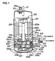
- FIG. 1 is a schematic vertical sectional view showing an embodiment in which the present invention is applied to a two-cylinder rotary compressor
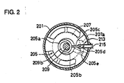
- FIG. 2 is a partial schematic cross sectional view of a rotary compressing element in the two-cylinder rotary compressor in FIG. 1.
- the reference numeral 201 denotes a metallic closed vessel
- the dosed vessel 201 is provided so that an inverter type motor-operating element 202 and a rotary compressing element 203 driven by the motor-operating element 202 are positioned at upper and lower portions within the closed vessel respectively.
- the motor-operating element 202 is comprised of a substantially annular stator 202a fixed to an inner surface of the closed vessel 201 and a rotor 202b, which rotates in the stator 202a.
- the rotor 202a is joumalled to an upper end portion of a rotating shaft 209.
- the rotary compressing element 203 includes a first rotary compressing element 204 and a second rotary compressing element 205 positioned below the rotary compressing element 204. These first and second rotary compressing elements are partitioned by a partition plate 206. A lower bearing member 207 is attached to a lower portion of the second rotary compressing member 205 and an upper bearing member 208 is attached to an upper portion of the first rotary compressing element 204 so that said rotating shaft 209 is supported.
- a terminal 210 is attached to an upper end portion of the closed vessel 201, and a plurality of connection terminals 210a penetrating through the terminal 210 are connected to a stator 202a of the motor-operating element 202 through internal lead wires not shown and are connected to an external power source through external lead wires.
- the stator 202a is energized through the terminal 210, the rotor 202b is rotated, and the rotation rotates the rotating shaft 209. Further, to an upper end portion of the closed vessel 201 is attached a discharge pipe 211.
- a first eccentric portion 209a and a second eccentric portion 209b are provided on the rotating shaft 209 with a phase shifted by 180°.
- a first roller 204a in said first rotary compressing element 204 and to the second eccentric portion 209b is fitted a second roller 205a in the second rotary compressing element 205.
- the first roller 204a is eccentrically rotated in a first compressing chamber 204b in the first rotary compressing element 204 and the second roller 205a is eccentrically rotated in a second compressing chamber 205b in the second rotary compressing element 205.
- a first vane 204c is biased by a spring 212 to be always in press-contact with the first roller 204a, so that the first compressing chamber 204b is defined between a low-pressure chamber and a high-pressure chamber although not shown. Further, in the first rotary compressing element 204 is provided a first through hole 204d, which communicates with a back pressure portion of the first vane 204c. A back pressure is applied to the back pressure portion of the first vane 204c by passing of high pressure refrigerant gas in the closed vessel through the first through hole 204d.
- the second rotary compressing element 205 is not provided with a spring, which biases a second vane 205c.
- a high-pressure refrigerant gas is supplied to a back pressure portion of the second vane 205c through a refrigerant gas switching means 214 to be described later, the second vane 205c is pressed to press-contact with the second roller 205a.
- the second compressing chamber 205b is defined between a low-pressure chamber and a high pressure chamber although not shown. As a result the second rotary compressing element 205 becomes in a compressible operating state.
- the second compressing chamber 205b is not defined to a low pressure chamber and a high pressure chamber so that the second rotary compressing element 205 becomes in non-compressible and non-operating state.
- a second through hole 205d in the second rotary compressing element 205 is closed by a sealing member 213 to be shut off so that a high-pressure refrigerant gas in the closed vessel 201 does not pass through the second through hole 205d so as not to apply a back pressure to the second vane 205c.
- the sealing member 213 Is formed in such a manner that for example a part of the outer circumferential end portion of the partition plate 206 is extended outside, an upper end of the second through hole 205d is dosed by this extended portion 206a, a part of the outer circumferential end portion of the lower bearing member 207 is extended outside, and a lower end of the second through hole 205d is closed by this extended portion 207a (see FIG. 2).
- the sealing member 213 is not limited to the above-mentioned example and may be a member, which can dose the second through hole 205d. In case where the second through hole 205d is not previously provided in the second rotary compressing element 205, the sealing member 213 is not needed.
- An example of the refrigerant gas switching means 214 is comprised of for example, as shown in FIG. 1, a communicating pipe 215, attached to the outside of the closed vessel 201 in such a manner that one end of the pipe 215 Is opened in the closed vessel 201 and the other end of the pipe 215 is opened in a back pressure portion 205e of the second vane 205c in the second rotary compressing element 205, a branch pipe 216 provided at an intermediate portion of the communicating pipe 215 In a branched manner, and a three-way valve 217 attached to the branch point of the branch pipe 216.
- the refrigerant gas switching means 214 may be comprised of, although not shown, a communicating pipe, attached to the outside of the closed vessel 201 in such a manner that one end of the pipe is opened in the dosed vessel 201 and the other end of the pipe is opened in a back pressure portion 205e of the second vane 205c in the second rotary compressing element 205, and an open/close valve mounted in a midway portion of the communicating pipe. In this case it is not necessary to provide the branch pipe 216.
- a low pressure refrigerant gas is supplied to the first rotary compressing element 204 and the second rotary compressing element 205 in the rotary compressing element 203 through introduction pipes not shown respectively.
- the stator 202a of the inverter type motor-operating element 202 is energized through the terminal 210, the rotor 202b is rotated to rotate the rotating shaft 209 and the rotary compressing element 203 is operated to compress a refrigerant gas.
- Both high pressure refrigerant gases compressed in the first rotary compressing element 204 and the second rotary compressing element 205 in the rotary compressing element 203 are discharged into the closed vessel 201.
- the high pressure refrigerant gas discharged Into the dosed vessel 201 is taken out outside the closed vessel 201 through the discharge pipe 211 and is supplied to a refrigerating cycle in an air conditioner or the like. Then the refrigerant gas circulated in the refrigerating cycle is returned to the compressor from an accumulator (not shown).
- said motor-operating element 202 is an inverter type, the number of revolutions of the rotating shaft 209 can be controlled by adjusting the frequency.
- the three-way valve 217 of said refrigerant gas switching means 214 is switched so that a part of the high pressure refrigerant gas in the closed vessel 201 is supplied to the back pressure portion 205e of the second vane 205c in the second rotary compressing element 205 through the communicating pipe 215.
- the second vane 205c is pressed by the high pressure refrigerant gas supplied to the back pressure portion 205e to be brought Into press-contact with said second roller 205a so that the second compressing chamber 205b is defined between a low pressure chamber and a high pressure chamber.
- the second rotary compressing element 205 is maintained in an operation mode.
- both the first rotary compressing element 204 and the second rotary compressing element 205 are operated.
- the first vane 204c in the first rotary compressing element 204 is biased by said spring 212 to be brought into press-contact with the first roller 204a.
- the compression operations of the refrigerant gases in the first rotary compressing element 204 and the second rotary compressing element 205 are substantially the same.
- an example for the first rotary compressing element 204 will be explained.
- the refrigerant gas Introduced to said introduction pipe (not shown) is sucked from a suction port (not shown) to the low pressure chamber of said first compressing chamber 204b and is compressed by eccentric rotation of the first roller 204a. After that the refrigerant gas is discharged from the high-pressure chamber into the closed vessel 201 through a discharge port (not shown).
- the three-way valve 217 of said refrigerant gas switching means 214 is switched so that the high refrigerant gas flowed from the closed vessel 201 into the communicating pipe 215 is relieved to the branch pipe 216.
- the high-pressure refrigerant gas is not supplied to the back pressure portion 205e of the second vane 205c in the second rotary compressing element 205 through the communicating pipe 215. Consequently, the second vane 205c is not pressed by the high-pressure refrigerant gas so that it is not brought into press-contact with the second roller 205e.
- the second through hole 205d in the second rotary compressing element 205 is dosed by the sealing member 213, the high pressure refrigerant gas in the closed vessel 201 is shut off by the sealing member 213 and does not enter the second through hole 205d.
- the second vane 205c is not pressed even by the high-pressure refrigerant gas in the closed vessel 201 and is maintained in a state where the second vane 205c is not brought into press-contact with the second roller 205a.
- the second compressing chamber 205b cannot be defined between a low pressure chamber and a high pressure chamber whereby the second rotary compressing element 205 is made in a non-operation mode.
- the amount of high-pressure refrigerant gas discharged into the closed vessel 201 is reduced. Then, if the number of revolutions of the rotating shaft 209 for example is increased to about two times, an operation of pump and motor can be made in good efficiency so that COP at small capacity can be improved. In case where the two-cylinder rotary compressor is incorporated into an air conditioner, the variable range of capacity of the air conditioner is increased.
- the present invention is not limited to the above-mentioned two-cylinder rotary compressor and may be adapted to three or more-cylinder compressor by appropriately modifying said refrigerant gas switching means. Further, the multicylinder rotary compressor according to the present invention can be used by incorporating it not only to an air conditioner but also to a refrigerator, a freezer, a bending machine or the like.
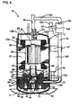
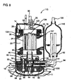
- FIG. 4 is a vertical sectional side view showing a first embodiment of a compressing system CS according to the present invention.
- FIG. 5 shows a vertical sectional side view (shown by a cross-section different from FIG. 4) of a rotary compressor 10 in FIG. 4. It is noted that the compressing system CS of the present example forms a part of a refrigerant circuit of an air-conditioner as a refrigerating unit, which air-conditions rooms.
- Said rotary compressor 10 is an internal high-pressure type rotary compressor provided with first and second rotary compressing elements, and accommodates a motor-operating element 14 as a driving element, disposed on the upper side of the internal space in the closed vessel 12 and a rotary compressing mechanism portion 18 comprised of first and second rotary compressing elements 32 and 34, disposed on the lower side of the motor-operating element 14 and which is driven by the rotating shaft 16 of the motor-operating element 14.
- the closed vessel 12 is comprised of a vessel body 12A, whose bottom portion is used as an oil reservoir and which accommodates the motor-operating element 14 and the rotary compressing mechanism portion 18, and a substantially bowl-shaped end cap (lid body) 12B, which closes an upper opening of the vessel body 12A. Also a circular mounting hole 12D Is formed on an upper surface of the end cap 12B and to the mounting hole 12D is attached a terminal (wirings omitted) 20, which supplies the motor-operating element 14 with electric power.
- a refrigerant discharge pipe 96 to be described later, and an end of the refrigerant discharge pipe 96 communicates with the inside of the closed vessel 12.
- a mounting pedestal 11 is provided on a bottom portion of the closed vessel 12.
- the motor-operating element 14 is comprised of a stator 22 welded in an annular shape along the inner circumferential surface of upper space in the closed vessel 12 and a rotor 24 inserted inside the stator 22 with a small gap. This rotor 24 is fixed to a rotating shaft 16 passing through the center and extending in the vertical direction.
- Said stator 22 has a laminated body 26 laminated with donut-shaped electromagnetic steel sheets and a stator coil 28 wound around teeth portions of the laminated body 26 by a series winding (concentration winding) method. Further, the rotor 24 is made of a laminated body 30 laminated with electromagnetic steel sheets like the stator 22.
- the first rotary compressing element 32 and the second rotary compressing element 34 are comprised of an intermediate partition plate 36, first and second cylinders 38 and 40, disposed on the upper and lower sides of the intermediate partition plate 36, first and second rollers 46 and 48, fitted respectively onto upper and lower eccentric portions 42 and 44 provided on the rotating shaft 16 in the first and second cylinders 38 and 40 with a phase difference of 180° therebetween, and which respectively eccentrically rotates in the respective cylinders 38 and 40, first and second vanes 50 and 52, which abut on the first and second rollers 46 and 48 respectively and divide the insides of the respective cylinders 38 and 40 into a low pressure chamber side and a high pressure chamber side respectively, an upper supporting member 54 and a lower supporting member 56 as supporting members, which close an upper opening surface of the first cylinder 38 and a lower opening surface of the second cylinder 40 respectively and also serve as bearing for the rotating shaft 16.
- the first and second cylinders 38 and 40 are provided with respective suction passages 58 and 60 communicating with the insides of said first and second cylinders 38 and 40 respectively, and to the suction passages 58 and 60 are respectively connected refrigerant introduction pipes 92 and 94 to be described later.
- a discharge muffling chamber 62 is provided on the upper side of the upper supporting member 54 and the refrigerant gas compressed by the first rotary compressing element 32 is discharged into said discharge muffling chamber 62.
- the discharge muffling chamber 62 is formed inside a substantially bowl-shaped cup member 63, which has a hole for the rotating shaft 16 and the upper supporting member 54, which also acts as a bearing of the rotating shaft 16. to let them penetrate at the center and covers the motor-operating element 14 side (upper side) of the upper supporting member 54. Then the motor-operating element 14 is provided above the cup member 63 with a predetermined space with respect to the cup member 63.
- the lower supporting member 56 is provided with a discharge muffling chamber 64 formed by closing a recess portion formed on the lower side of said lower supporting member 56 with a cover as a wall. That is the discharge muffling chamber 64 is closed by a lower cover 68 defining the discharge muffling chamber 64.
- a guide groove 70 which accommodates the above-mentioned first vane 50, and on the outside of the guide groove 70, that is on the back surface side of the first vane 50 is formed an accommodating portion 70A, which accommodates a spring 74 as a spring member.
- the spring 74 abuts on a back surface side end portion of the first vane 50 and always biases the first vane 50 against the first roller 46 side.
- a discharge side pressure high pressure
- the accommodating portion 70A is opened on the guide groove 70 side and on the closed vessel 12 (vessel body 12A) side, and a metallic plug 137 is provided on the dosed vessel 12 side of the spring 74 accommodated in the accommodating portion 70A and acts as a coming-off stopper for the spring 74.
- a guide groove 72 which accommodates the second vane 52, and on the outside of the guide groove 72, that is on the back surface side of the second vane 52 is formed a back pressure chamber 72A.
- the back pressure chamber 72A is opened on the guide groove 72 side and on the closed vessel 12 side, and with the dosed vessel 12 side opening communicates a pipeline 75 to be described later while sealed between the pipeline 75 and the closed vessel 12.
- sleeves 141 and 142 To the side surface of the vessel body 12A of the closed vessel 12 are respectively welded sleeves 141 and 142 at the positions corresponding to the suction passages 58 and 60 of the first cylinder 38 and the second cylinder 40 respectively. These sleeves 141 and 142 abut on each other vertically.
- a refrigerant introduction pipe 92 for introducing a refrigerant gas into the first cylinder 38, and one end of this refrigerant introduction pipe 92 communicates with a suction passage 58 in the upper cylinder 38.
- the other end of the refrigerant introduction pipe 92 is opened in an accumulator 146.
- a refrigerant introduction pipe 94 for introducing a refrigerant gas into the second cylinder 40, and one end of this refrigerant introduction pipe 94 communicates with a suction passage 60 in the second cylinder 40.
- the other end of the refrigerant introduction pipe 94 is opened in an accumulator 146 as in the refrigerant introduction pipe 92.
- the accumulator 146 is a tank for separating gas/liquid in a suction refrigerant and is attached to the upper side of the vessel body 12A of the closed vessel 12 through a bracket 147. Then to the accumulator 146 are inserted the refrigerant introduction pipe 92 and the refrigerant introduction pipe 94 through a bottom portion and openings of the other ends are respectively positioned in the accumulator 146. Further, to an upper portion in the accumulator 146 is inserted an end of a refrigerant plpeline 100.
- the discharge muffling chamber 62 and the discharge muffling chamber 64 communicates with each other through a communicating passage 120, which penetrates through the upper and lower supporting members 54 and 56, the first and second cylinders 38 and 40, and the partition plate 36 In the axial direction (vertically). Then a high temperature, high pressure refrigerant gas compressed by the second rotary compressing element 34 and discharged into the discharge muffling chamber 64 is discharged into the discharge muffling chamber 62 through said communicating passage 120 and is joined with a high temperature, high pressure refrigerant gas compressed by the first rotary compressing element 32.
- the discharge muffling chamber 62 and the inside of the closed vessel 12 communicate with each other through a hole not shown, which penetrates through the cup member 63, and the high pressure refrigerant gas compressed by the first rotary compressing element 32 and second rotary compressing element 34 and discharged into the discharge muffling chamber 62 is discharged into the closed vessel 12.
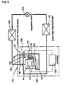
- a refrigerant pipeline 101 to a midway portion of the refrigerant pipeline 100 is connected a refrigerant pipeline 101, and the pipeline 101 is connected to the above-mentioned pipeline 75 through a solenoid valve 105.
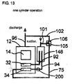
- a refrigerant pipeline 102 to a midway portion of the refrigerant discharge pipe 96 is connected to a refrigerant pipeline 102, and the pipeline 102 is connected to the pipeline 75 through a solenoid valve 106 like the refrigerant pipeline 101.
- the opening/closing of the solenoid valves 105 and 106 is controlled by a controller 130 to be described later, respectively. That is when the valve unit 105 is opened by the controller 130 and the valve unit 106 is closed, the refrigerant pipeline 101 communicates with the pipeline 75.
- valve unit 105 when the valve unit 105 is closed and the valve unit 106 is opened by the controller 130, the refrigerant discharge valve 96 and the pipeline 75 are caused to communicate with each other. Consequently, a part of discharge side refrigerants of both rotary compressing elements 32 and 34, which are discharged from the closed vessel 12 and pass through the refrigerant discharge pipe 96 passes through the refrigerant pipeline 102 and flows into the back pressure chamber 72A through the pipeline 75. As a result the discharge side pressure of both rotary compressing elements 32 and 34 are applied as the back pressure of the second vane 52.
- controller 130 forms a part of the compressing system CS of the present invention, and controls the number of revolutions of the motor-operating element 14 of the rotary compressor 10. Further, the controller 130 also controls the opening/closing of the solenoid-valve 105 in the refrigerant pipeline 101 and of the solenoid-valve 106 in the refrigerant pipeline 102.
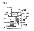
- FIG. 6 shows a refrigerant circuit diagram in the air-conditioner formed by use of the compression system CS. That is the compressing system CS of the present example forms a part of refrigerant circuit of the air-conditioner shown in FIG. 6 and is comprised of the above-mentioned rotary compressor 10, the controller 130 and the like.
- a refrigerant discharge pipe 96 In the rotary compressor 10 is connected to an inlet of an outdoor side heat exchanger 152.
- the controller 130, the rotary compressor 10 and the outdoor side heat exchanger 152 are provided in an outdoor side machine (not shown) for the air-conditioner.
- a pipeline connected to the outlet of this outdoor side heat exchanger 152 is connected to an expansion valve 154 as a pressure-reducing means and the pipeline extending from the expansion valve 154 is connected to the indoor side heat exchanger 156.
- These expansion valve 154 and the indoor side heat exchanger 156 are provided in an Indoor side machine (not shown) for the air-conditioner. Further, to the outlet side of the indoor side heat exchanger 156 is connected said refrigerant pipeline 100 in the rotary compressor 10.
- an HFC base or an HC base refrigerant is used, and oil as lubricating oil, existing oil such as a mineral oil, an alkyl benzene oil, an ether oil, an ester oil or the like, is used.
- the controller 130 controls the number of revolutions of the motor-operating element 14 of the rotary compressor 10 in accordance with an operation command input from the controller (not shown) on the indoor side machine side provided in the above mentioned indoor machine, and at the same time in case where the indoor side is under generally loaded conditions or highly loaded conditions, the controller 130 executes a first operation mode.
- the controller 130 doses the solenoid-valve 105 of the refrigerant pipeline 101 and the solenoid-valve 106 of the refrigerant pipeline 102 in this first operation mode (see FIG. 7).
- a low-pressure refrigerant flows into the accumulator 146 through the refrigerant pipeline 100 of the rotary compressor 10. Since the solenoid valve 105 of the refrigerant pipeline 101 is in a closed mode as mentioned above, all refrigerants, passing through the refrigerant pipeline 100 flow into the accumulator 146 without flowing into the pipeline 75.
- refrigerant gas After the low-pressure refrigerant which flowed into the accumulator 146 is gas/liquid separated there, only refrigerant gas enters the respective refrigerant introduction pipes 92 and 94 opened in said accumulator 146.
- a low-pressure refrigerant gas entered the refrigerant introduction pipe 92 passes through the suction passage 58 and is sucked into the low-pressure chamber side of the first cylinder 38 in the first rotary compressing element 32.
- the refrigerant gas sucked into the low-pressure chamber side of the first cylinder 38 is compressed by operations of the first roller 46 and first vane 50 and becomes a high temperature, high pressure refrigerant gas. Then the refrigerant gas passes through a discharge port (not shown) from the high pressure chamber side of the first cylinder 38 and is discharged into the discharge muffling chamber 62.
- the low-pressure refrigerant gas entered the refrigerant introduction pipe 94 passes through the suction passage 60 and is sucked into the low-pressure chamber side of the second cylinder 40 in the second rotary compressing element 34.
- the refrigerant gas sucked into the low-pressure chamber side of the second cylinder 40 is compressed by operations of the second roller 48 and second vane 52.
- the inside of the pipeline 75 connected to the back pressure chamber 72A of the second vane 52 is a closed space. Further, into the back pressure chamber 72A flows not a little amount of refrigerant in the second cylinder 40 from between the second vane 52 and the accommodating portion 70A. Accordingly, the pressure in the back pressure chamber 72A in the second vane 52 reaches an intermediate pressure between the suction side pressure and the discharge side pressure of both rotary compressing elements 32 and 34, and conditions where this intermediate pressure is applied as a back pressure for the second vane 52 are formed. This intermediate pressure allows the second vane 52 to be sufficiently biased against the second roller 48 without use of a spring member.
- the refrigerant gas which was compressed by the operations of the second roller 48 and second vane 52 and became In high temperature and high pressure, passes through the inside of the a discharge port (not shown) from the high pressure chamber side of the second cylinder 40 and is discharged into the discharge muffling chamber 64.
- the refrigerant gas discharged into the discharge muffling chamber 64 passes through the communicating passage 120 and is discharged into the discharge muffling chamber 62, and then joined with the refrigerant gas compressed by the first rotary compressing element 32. Then the joined refrigerant gas is discharged into the closed vessel 12 through a hole (not shown) penetrating through the cup member 63.
- the refrigerant in the dosed vessel 12 is discharged from the refrigerant discharge pipe 96 formed in the end cap 12B of the dosed vessel 12 to the outside and flows into the outdoor side heat exchanger 152.
- the refrigerant gas is heat-dissipated there and pressure-reduced by the expansion valve 154.
- the refrigerant gas flows into the indoor side heat exchanger 156.
- the refrigerant is evaporated in the indoor side heat exchanger 156 and absorbs heat from air circulated in the room so that it exhibits cooling action to cool the room. Then the refrigerant repeats a cycle of leaving the indoor side heat exchanger 156 and being sucked into the rotary compressor 10.
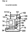
- FIG. 8 shows a vertical sectional side view of an inside high pressure type rotary compressor 110 provided with first and second rotary compressing elements as a multicylinder rotary compressor of a compressing system CS in this case. It is noted that In FIG. 8, reference numerals denoted by the same numerals as in FIGS. 4 to 7 exhibit the same effects.
- the reference numeral 200 denotes a valve unit and is provided on the outlet side of an accumulator 146 and in the midway portion of a refrigerant introduction pipe 94 on the inlet side of a closed vessel 12.
- the solenoid-valve (valve unit) 200 is a valve unit for controlling inflow of a refrigerant into a second cylinder 40 and is controlled by the above-mentioned controller 130 as a control device.
- an HFC base or HC base refrigerant is used as in the above-mentioned example, and oil as lubricating oil, existing oil such as mineral oil, alkyl benzene oil, ether oil, or ester oil is used.
- the controller 130 controls the number of revolutions of the motor-operating element 14 of the rotary compressor 110 in accordance with an operation command input from the controller (not shown) of the indoor side machine provided in the above-mentioned indoor machine, and at the same time in case where the indoor side is under generally loaded conditions or highly loaded conditions, the controller 130 executes a first operation mode.
- the controller 130 opens the solenoid-valve 200 of the refrigerant introduction pipe 94 and closes the solenoid-valve 105 of the refrigerant pipeline 101 and the solenoid-valve 106 of the refrigerant pipeline 102 in this first operation mode.
- a low-pressure refrigerant flows into the accumulator 146 through the refrigerant pipeline 100 of the rotary compressor 110. Since the solenoid valve 105 of the refrigerant pipeline 101 is in a closed mode as mentioned above, all refrigerants, passing through the refrigerant pipeline 100 flow into the accumulator 146 without flowing into the pipeline 75.
- refrigerant gas After the low-pressure refrigerant which flowed into the accumulator 146 is gas/liquid separated there, only refrigerant gas enters the respective refrigerant introduction pipes 92 and 94 opened in said accumulator 146.
- a low-pressure refrigerant gas entered the introduction pipes 92 passes through the suction passage 58 and is sucked into a low-pressure chamber side of the first cylinder 38 in the first rotary compressing element 32.
- the refrigerant gas sucked into the low-pressure chamber side of the first cylinder 38 is compressed by operations of the first roller 46 and first vane 50 and becomes a high temperature, high pressure refrigerant gas. Then the refrigerant gas passes through a discharge port (not shown) from the high-pressure chamber side of the first cylinder 38 and is discharged into the discharge muffling chamber 62.
- the low-pressure refrigerant gas entered the refrigerant introduction pipe 94 passes through the suction passage 60 and is sucked Into the low-pressure chamber side of the second cylinder 40 in the second rotary compressing element 34.
- the refrigerant gas sucked into the low-pressure chamber side of the second cylinder 40 is compressed by operations of the second roller 48 and second vane 52.
- the inside of the pipeline 75 connected to the back pressure chamber 72A of the second vane 52 is a dosed space. Further, into the back pressure chamber 72A flows not a little amount of refrigerant in the second cylinder 40 from between the second vane 52 and the accommodating portion 70A. Accordingly, the pressure in the back pressure chamber 72A in the second vane 52 reaches an intermediate pressure between the suction side pressure and the discharge side pressure of both rotary compressing elements 32 and 34, and conditions where this intermediate pressure is applied as a back pressure for the second vane 52 are formed. This intermediate pressure allows the second vane 52 to be sufficiently biased against the second roller 48 without use of a spring member.
- the refrigerant gas which was compressed by the operations of the second roller 48 and second vane 52 and became in high temperature and high pressure, passes through the inside of the a discharge port (not shown) from the high pressure chamber side of the second cylinder 40 and is discharged into the discharge muffling chamber 64.
- the refrigerant gas discharged into the discharge muffling chamber 64 passes through the communicating passage 120 and is discharged into the discharge muffling chamber 62, and then joined with the refrigerant gas compressed by the first rotary compressing element 32. Then the joined refirlgerant gas is discharged into the closed vessel 12 through a hole (not shown) penetrating through the cup member 63.
- the refrigerant in the closed vessel 12 is discharged from the refrigerant discharge pipe 96 formed in the end cap 128 of the closed vessel 12 to the outside and flows into the outdoor side heat exchanger 162.
- the refrigerant gas is heat-dissipated there and pressure-reduced by the expansion valve 154.
- the refrigerant gas flows into the indoor side heat exchanger 156.
- the refrigerant is evaporated in the indoor side heat exchanger 156 and absorbs heat from air circulated in the room so that it exhibits cooling action to cool the room. Then the refrigerant repeats a cycle of leaving the indoor side heat exchanger 156 and being sucked Into the rotary compressor 110.
- the second mode Is a mode where substantially only the first rotary compressing element 32 execute compression-work and is an operation mode, which is performed in case where the indoor inside becomes under lightly loaded conditions and the motor-operating element 14 becomes low speed rotation in the first operation mode.
- the second mode Is a mode where substantially only the first rotary compressing element 32 execute compression-work and is an operation mode, which is performed in case where the indoor inside becomes under lightly loaded conditions and the motor-operating element 14 becomes low speed rotation in the first operation mode.
- the amount of compressing refrigerant gas can be more reduced than in case where compression work is executed by both first and second cylinders 38 and 40.
- the number of revolutions of the motor-operating element 14 can be increased even under lightly loaded conditions by the part of the reduced amount of refrigerant gas, the operation efficiency of the motor-operating element 14 can be improved and the leakage loss of refrigerant gas can be reduced.
- the controller 130 closes the above-mentioned solenoid-valve 200 to block the inflow of refrigerant gas to the second cylinder 40. Consequently, compression work is not executed in the second rotary compressing element 34, Further, when the inflow of refrigerant gas to the second cylinder 40 is blocked, the inside of the second cylinder 40 reaches a little higher pressure than suction side pressure of the above-mentioned both rotary compressing elements 32 and 34 (this is because the second roller 48 is rotated and the high pressure inside the closed vessel 12 slightly flows into the second cylinder 40 through a gap or the like of the second cylinder 40, resulting in that the inside of the second cylinder 40 reaches a little higher pressure than the suction side pressure).
- the controller 130 opens the solenoid-valve 105 of the refrigerant pipeline 101 and doses the solenoid-valve 106 of the refrigerant pipeline 102.
- the refrigerant pipeline 101 communicates with the pipeline 75 so that the suction side refrigerant in the first rotary compressing element 32 flows into the back pressure chamber 72A, resulting in that as back pressure of the second vane 52 the suction side pressure in the first rotary compressing element 32 is applied.
- the controller 130 energizes the stator coil 28 of the motor-operating element 14 through the above-mentioned terminal 20 end wiring not shown to rotate the rotor 24 of the motor-operating element 14.
- the first and second rollers 46 and 48 are respectively fitted onto the upper and lower eccentric portions 42 and 44 integrally provided with the rotating shaft 16 to be rotated eccentrically in the first and second cylinders 38 and 40, respectively.
- a low-pressure refrigerant flows into the accumulator 146 through the refrigerant pipeline 100 of the rotary compressor 110.
- the solenoid valve 105 of the refrigerant pipeline 101 Is in an open mode as mentioned above, a part of the suction side refrigerant in the first rotary compressing element 32, which passes through the refrigerant pipeline 100 flows into the back pressure chamber 72A from the refrigerant pipeline 101 through the pipe line 76.
- the back pressure chamber 72A reaches a suction side pressure in the first rotary compressing element 32 and as a back pressure for the second vane 52 the suction side pressure In the first rotary compressing element 32 Is applied.
- the solenoid valve 200 is closed to block the inflow of refrigerant into the second cylinder 40 so that the inside of the second cylinder 40 is set at pressure higher than the suction side pressure in the first rotary compressing element 32 as in the present invention
- the pressure in the second cylinder 40 becomes higher than the back pressure for the second vane 52 by applying suction side pressure in the first rotary compressing element 32 as a back pressure for the second vane 52.
- the second vane 52 is pressed to the back pressure chamber 72A side, which is the opposite side to the second roller 48, by pressure in the second cylinder 40, so that the second vane 52 is not protruded in the second cylinder 40.
- the second vane 52 is protruded in the second cylinder 40 and coilides with the second roller 48 to produce collision noise can be previously avoided.
- the refrigerant gas sucked into the low-pressure chamber side of the first cylinder 38 is compressed by operations of the first roller 46 and first vane 50 and becomes a high temperature, high pressure refrigerant gas. Then the refrigerant gas passes through a discharge port (not shown) from the high-pressure chamber side of the first cylinder 38 and is discharged into the discharge muffling chamber 62. Then, since in the second operation mode, the discharge muffling chamber 62 functions as an expansion type muffling chamber and the discharge muffling chamber 64 functions as a resonance type muffling chamber, the pressure pulsation of the refrigerant compressed by the first rotary compressing element 32 can be further reduced. Accordingly, in the second operation mode where compression work is executed by substantially only the first rotary compressing element 32, the muffling effect can be further improved.
- the refrigerant gas discharged into the discharge muffling chamber 62 is discharged into the closed vessel 12 through a hole (not shown) penetrating through the cup member 63.
- the refrigerant in the dosed vessel 12 is discharged from the refrigerant discharge pipe 96 formed in the end cap 12B of the dosed vessel 12 to the outside and flows into the outdoor side heat exchanger 152.
- the refrigerant gas is heat-dissipated there and pressure-reduced by the expansion valve 154.
- the refrigerant gas flows into the indoor side heat exchanger 156.
- the refrigerant is evaporated in said indoor side heat exchanger 156 and absorbs heat from air circulated In the room so that it exhibits cooling action to cool the room. Then the refrigerant repeats a cycle of leaving the indoor side heat exchanger 156 and being sucked into the rotary compressor 110.
- a compressing system CS provided with a rotary compressor 110 usable by switching between a first operation mode where the first and second rotary compressing elements 32 and 34 execute compression work and the second operation mode where substantially only the first rotary compressing element 32 executes compression work, can be effected.
- a refrigerant obtained by combination of refrigerants having large pressure difference between high and low pressures such as carbon dioxide, for example carbon dioxide and PAG (polyalkyl glycol) as a refrigerant, may be used.
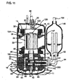
- refrigerants compressed by the respective rotary compressing elements 32 and 34 reach very high pressure, when the discharge muffling chamber 62 has such shape that an upper side of the upper supporting member 54 is covered with the cup member 63 as in the respective examples, the cup member 63 may be broken by such high pressure.
- a shape of an upper side discharge muffling chamber of the upper supporting member 54 where the refrigerants compressed by both rotary compressing elements 32 and 34 are joined with each other is designed as a shape as shown in FIG. 11, the pressure tightness can be ensured.
- a discharge muffling chamber 162 is formed by forming a recess portion on the upper side of the upper supporting member 54 and dosing the recess portion with an upper cover 66 as a cover. Consequently, even if a refrigerant contains a refrigerant having large pressure difference between high and low pressures such as carbon dioxide, the present invention can be applied.
- the present invention may be applied to a compressing system provided with a multicylinder rotary compressor provided with a three-cylinder or more rotary compressing element.
- the multicylinder rotary compressor according to the present invention and a compressing system and a refrigerating unit each provided with the multicylinder rotary compressor can be preferably utilized for various air conditioners as well as a refrigerator, a freezer, a freezer/refrigerator, and the like.
Landscapes
- Engineering & Computer Science (AREA)
- Mechanical Engineering (AREA)
- General Engineering & Computer Science (AREA)
- Applications Or Details Of Rotary Compressors (AREA)
Priority Applications (1)
| Application Number | Priority Date | Filing Date | Title |
|---|---|---|---|
| EP05022234A EP1617082B1 (fr) | 2004-03-15 | 2005-03-09 | Compresseur multi-cylindres à pistons rotatifs et système de compression et unité de réfrigération le comprenant |
Applications Claiming Priority (4)
| Application Number | Priority Date | Filing Date | Title |
|---|---|---|---|
| JP2004073229A JP2005256815A (ja) | 2004-03-15 | 2004-03-15 | 多気筒回転圧縮機 |
| JP2004073229 | 2004-03-15 | ||
| JP2004191210A JP2006009756A (ja) | 2004-06-29 | 2004-06-29 | 圧縮システム及びそれを用いた冷凍装置 |
| JP2004191210 | 2004-06-29 |
Related Child Applications (2)
| Application Number | Title | Priority Date | Filing Date |
|---|---|---|---|
| EP05022234A Division EP1617082B1 (fr) | 2004-03-15 | 2005-03-09 | Compresseur multi-cylindres à pistons rotatifs et système de compression et unité de réfrigération le comprenant |
| EP05022234.8 Division-Into | 2005-10-12 |
Publications (3)
| Publication Number | Publication Date |
|---|---|
| EP1577557A2 true EP1577557A2 (fr) | 2005-09-21 |
| EP1577557A3 EP1577557A3 (fr) | 2006-03-08 |
| EP1577557B1 EP1577557B1 (fr) | 2013-08-07 |
Family
ID=34840239
Family Applications (2)
| Application Number | Title | Priority Date | Filing Date |
|---|---|---|---|
| EP05022234A Not-in-force EP1617082B1 (fr) | 2004-03-15 | 2005-03-09 | Compresseur multi-cylindres à pistons rotatifs et système de compression et unité de réfrigération le comprenant |
| EP05005174.7A Not-in-force EP1577557B1 (fr) | 2004-03-15 | 2005-03-09 | Système de compression avec compresseur multi-cylindres à pistons rotatifs et unité de réfrigération comprenant ce système |
Family Applications Before (1)
| Application Number | Title | Priority Date | Filing Date |
|---|---|---|---|
| EP05022234A Not-in-force EP1617082B1 (fr) | 2004-03-15 | 2005-03-09 | Compresseur multi-cylindres à pistons rotatifs et système de compression et unité de réfrigération le comprenant |
Country Status (6)
| Country | Link |
|---|---|
| US (1) | US7563085B2 (fr) |
| EP (2) | EP1617082B1 (fr) |
| KR (1) | KR20060043610A (fr) |
| CN (1) | CN100529407C (fr) |
| AT (1) | ATE513996T1 (fr) |
| TW (1) | TW200530509A (fr) |
Cited By (4)
| Publication number | Priority date | Publication date | Assignee | Title |
|---|---|---|---|---|
| EP1614902A2 (fr) * | 2004-07-08 | 2006-01-11 | Sanyo Electric Co., Ltd. | Système de compression |
| EP1672219A2 (fr) | 2004-12-13 | 2006-06-21 | Sanyo Electric Co., Ltd | Compresseur à piston rotatif |
| EP1806475A1 (fr) * | 2006-01-09 | 2007-07-11 | Samsung Electronics Co., Ltd. | Compresseur à piston rotatif |
| EP1992820A1 (fr) * | 2006-03-09 | 2008-11-19 | Daikin Industries, Ltd. | Dispositif de congelation |
Families Citing this family (17)
| Publication number | Priority date | Publication date | Assignee | Title |
|---|---|---|---|---|
| KR20060024739A (ko) * | 2004-09-14 | 2006-03-17 | 삼성전자주식회사 | 다기통 압축기 |
| JP2006291799A (ja) * | 2005-04-08 | 2006-10-26 | Matsushita Electric Ind Co Ltd | 密閉型ロータリ圧縮機 |
| KR100726454B1 (ko) * | 2006-08-30 | 2007-06-11 | 삼성전자주식회사 | 로터리 압축기 |
| KR100786994B1 (ko) * | 2006-10-17 | 2007-12-20 | 삼성전자주식회사 | 로터리 압축기 |
| KR20080068441A (ko) * | 2007-01-19 | 2008-07-23 | 삼성전자주식회사 | 용량가변 회전압축기 |
| JP2010163927A (ja) * | 2009-01-14 | 2010-07-29 | Toshiba Carrier Corp | 多気筒回転式圧縮機および冷凍サイクル装置 |
| US8794941B2 (en) | 2010-08-30 | 2014-08-05 | Oscomp Systems Inc. | Compressor with liquid injection cooling |
| US9267504B2 (en) | 2010-08-30 | 2016-02-23 | Hicor Technologies, Inc. | Compressor with liquid injection cooling |
| CN102588285B (zh) * | 2011-01-18 | 2014-05-07 | 珠海格力节能环保制冷技术研究中心有限公司 | 压缩机及具有该压缩机的空调器 |
| TWI582301B (zh) * | 2011-07-09 | 2017-05-11 | 周紹傳 | 活塞差速回轉引擎 |
| WO2014164622A1 (fr) * | 2013-03-11 | 2014-10-09 | Trane International Inc. | Commandes et utilisation de variateurs de fréquence |
| US10473367B2 (en) * | 2013-05-24 | 2019-11-12 | Mitsubishi Electric Corporation | Heat pump apparatus |
| CN103511262A (zh) * | 2013-06-21 | 2014-01-15 | 广东美芝制冷设备有限公司 | 旋转式压缩机、双缸旋转式压缩机和冷冻循环装置 |
| CN103410731B (zh) * | 2013-08-02 | 2018-02-06 | 广东美芝制冷设备有限公司 | 旋转压缩机和冷冻循环装置 |
| JP6349417B2 (ja) | 2014-03-03 | 2018-06-27 | 広東美芝制冷設備有限公司 | 二段回転式コンプレッサーおよび冷却サイクル装置 |
| WO2017008229A1 (fr) * | 2015-07-13 | 2017-01-19 | 广东美芝制冷设备有限公司 | Compresseur rotatif à cylindres multiples et appareil de circulation de réfrigération le comportant |
| CN105201850B (zh) * | 2015-10-26 | 2017-12-01 | 珠海格力节能环保制冷技术研究中心有限公司 | 一种压缩机 |
Citations (1)
| Publication number | Priority date | Publication date | Assignee | Title |
|---|---|---|---|---|
| JPH07229495A (ja) | 1994-02-21 | 1995-08-29 | Daikin Ind Ltd | 横形回転圧縮機 |
Family Cites Families (16)
| Publication number | Priority date | Publication date | Assignee | Title |
|---|---|---|---|---|
| JPS6229788A (ja) * | 1985-07-30 | 1987-02-07 | Mitsubishi Electric Corp | 多気筒回転式圧縮機 |
| JPS6357889A (ja) * | 1986-08-29 | 1988-03-12 | Toshiba Corp | 回転式圧縮機 |
| KR900003716B1 (ko) * | 1986-09-30 | 1990-05-30 | 미츠비시 덴키 가부시키가이샤 | 다기통 회전식 압축기 |
| JPS6480790A (en) * | 1987-09-21 | 1989-03-27 | Mitsubishi Electric Corp | Two-cylinder rotary compressor |
| JPH01193089A (ja) * | 1988-01-29 | 1989-08-03 | Toshiba Corp | ロータリコンプレッサー |
| JPH01247786A (ja) * | 1988-03-29 | 1989-10-03 | Toshiba Corp | 2シリンダ型ロータリ式圧縮機 |
| JP2555464B2 (ja) * | 1990-04-24 | 1996-11-20 | 株式会社東芝 | 冷凍サイクル装置 |
| JPH0599172A (ja) | 1991-10-03 | 1993-04-20 | Sanyo Electric Co Ltd | 2気筒回転圧縮機 |
| JPH05256286A (ja) * | 1992-03-13 | 1993-10-05 | Toshiba Corp | 多気筒型回転圧縮機 |
| JP3762043B2 (ja) * | 1997-01-17 | 2006-03-29 | 東芝キヤリア株式会社 | ロータリ式密閉形圧縮機および冷凍サイクル装置 |
| KR100466620B1 (ko) * | 2002-07-09 | 2005-01-15 | 삼성전자주식회사 | 용량가변형 회전압축기 |
| JP4343627B2 (ja) * | 2003-03-18 | 2009-10-14 | 東芝キヤリア株式会社 | ロータリ式密閉形圧縮機および冷凍サイクル装置 |
| KR20040100078A (ko) * | 2003-05-21 | 2004-12-02 | 삼성전자주식회사 | 능력가변 회전압축기 |
| JP4447859B2 (ja) * | 2003-06-20 | 2010-04-07 | 東芝キヤリア株式会社 | ロータリ式密閉形圧縮機および冷凍サイクル装置 |
| US8206128B2 (en) * | 2003-12-03 | 2012-06-26 | Toshiba Carrier Corporation | Refrigeration cycle system |
| TWI363137B (en) * | 2004-07-08 | 2012-05-01 | Sanyo Electric Co | Compression system, multicylinder rotary compressor, and refrigeration apparatus using the same |
-
2005
- 2005-02-02 TW TW094103161A patent/TW200530509A/zh not_active IP Right Cessation
- 2005-03-09 AT AT05022234T patent/ATE513996T1/de not_active IP Right Cessation
- 2005-03-09 EP EP05022234A patent/EP1617082B1/fr not_active Not-in-force
- 2005-03-09 EP EP05005174.7A patent/EP1577557B1/fr not_active Not-in-force
- 2005-03-11 CN CNB2005100545517A patent/CN100529407C/zh not_active Ceased
- 2005-03-14 US US11/079,929 patent/US7563085B2/en active Active
- 2005-03-14 KR KR1020050021009A patent/KR20060043610A/ko not_active Application Discontinuation
Patent Citations (1)
| Publication number | Priority date | Publication date | Assignee | Title |
|---|---|---|---|---|
| JPH07229495A (ja) | 1994-02-21 | 1995-08-29 | Daikin Ind Ltd | 横形回転圧縮機 |
Cited By (16)
| Publication number | Priority date | Publication date | Assignee | Title |
|---|---|---|---|---|
| US7524174B2 (en) | 2004-07-08 | 2009-04-28 | Sanyo Electric Co., Ltd. | Compression system, multicylinder rotary compressor, and refrigeration apparatus using the same |
| EP1614902A3 (fr) * | 2004-07-08 | 2006-05-10 | Sanyo Electric Co., Ltd. | Système de compression |
| EP1614902A2 (fr) * | 2004-07-08 | 2006-01-11 | Sanyo Electric Co., Ltd. | Système de compression |
| EP1813814A2 (fr) | 2004-07-08 | 2007-08-01 | Sanyo Electric Co., Ltd. | Système de compression |
| EP1813814A3 (fr) * | 2004-07-08 | 2007-10-17 | Sanyo Electric Co., Ltd. | Système de compression |
| US7572116B2 (en) | 2004-07-08 | 2009-08-11 | Sanyo Electric Co., Ltd. | Compression system, multicylinder rotary compressor, and refrigeration apparatus using the same |
| US7585163B2 (en) | 2004-07-08 | 2009-09-08 | Sanyo Electric Co., Ltd. | Compression system, multicylinder rotary compressor, and refrigeration apparatus using the same |
| EP1672219A2 (fr) | 2004-12-13 | 2006-06-21 | Sanyo Electric Co., Ltd | Compresseur à piston rotatif |
| EP1672219A3 (fr) * | 2004-12-13 | 2007-05-23 | Sanyo Electric Co., Ltd | Compresseur à piston rotatif |
| EP1933034A2 (fr) | 2004-12-13 | 2008-06-18 | Sanyo Electric Co., Ltd. | Compresseur rotatif |
| US7985054B2 (en) | 2004-12-13 | 2011-07-26 | Sanyo Electric Co., Ltd. | Multicylindrical rotary compressor, compression system, and freezing device using the compression system |
| EP1933034A3 (fr) * | 2004-12-13 | 2011-03-23 | Sanyo Electric Co., Ltd. | Compresseur rotatif |
| US7566204B2 (en) | 2004-12-13 | 2009-07-28 | Sanyo Electric Co., Ltd. | Multicylindrical rotary compressor, compression system, and freezing device using the compression system |
| EP1806475A1 (fr) * | 2006-01-09 | 2007-07-11 | Samsung Electronics Co., Ltd. | Compresseur à piston rotatif |
| EP1992820A1 (fr) * | 2006-03-09 | 2008-11-19 | Daikin Industries, Ltd. | Dispositif de congelation |
| EP1992820A4 (fr) * | 2006-03-09 | 2014-01-08 | Daikin Ind Ltd | Dispositif de congelation |
Also Published As
| Publication number | Publication date |
|---|---|
| US7563085B2 (en) | 2009-07-21 |
| EP1617082B1 (fr) | 2011-06-22 |
| EP1617082A3 (fr) | 2006-05-03 |
| EP1617082A2 (fr) | 2006-01-18 |
| EP1577557B1 (fr) | 2013-08-07 |
| ATE513996T1 (de) | 2011-07-15 |
| KR20060043610A (ko) | 2006-05-15 |
| TWI337223B (fr) | 2011-02-11 |
| CN1670374A (zh) | 2005-09-21 |
| EP1577557A3 (fr) | 2006-03-08 |
| TW200530509A (en) | 2005-09-16 |
| CN100529407C (zh) | 2009-08-19 |
| US20050214137A1 (en) | 2005-09-29 |
Similar Documents
| Publication | Publication Date | Title |
|---|---|---|
| EP1577557B1 (fr) | Système de compression avec compresseur multi-cylindres à pistons rotatifs et unité de réfrigération comprenant ce système | |
| EP1614902B1 (fr) | Système de compression et procédé | |
| JP4796073B2 (ja) | 容量可変型ロータリ圧縮機 | |
| US10309700B2 (en) | High pressure compressor and refrigerating machine having a high pressure compressor | |
| KR20060066662A (ko) | 다기통 회전 압축기, 압축 시스템 및 이를 사용한 냉동장치 | |
| US20110176949A1 (en) | Rotary compressor | |
| KR100620044B1 (ko) | 로터리 압축기의 용량 가변 장치 | |
| JP2007146747A (ja) | 冷凍サイクル装置 | |
| JP2007146663A (ja) | 密閉型圧縮機および冷凍サイクル装置 | |
| JP2006022723A (ja) | 圧縮システム及びそれを用いた冷凍装置 | |
| KR101328229B1 (ko) | 로터리식 압축기 | |
| KR100677525B1 (ko) | 로터리 압축기의 용량 가변 장치 | |
| US8651841B2 (en) | Rotary compressor with improved connection | |
| KR101194608B1 (ko) | 용량 가변형 로터리 압축기 | |
| JP2006022766A (ja) | 多気筒回転圧縮機 | |
| KR100677527B1 (ko) | 로터리 압축기 | |
| JP4024056B2 (ja) | ロータリコンプレッサ | |
| CN112412785B (zh) | 压缩机及冷冻循环装置 | |
| KR100585810B1 (ko) | 이중 셀을 구비한 용량 가변형 로터리 압축기 및 그 운전방법 | |
| JP4726444B2 (ja) | 多気筒回転圧縮機 | |
| JP4404708B2 (ja) | 圧縮システム及びそれを用いた冷凍装置 | |
| KR101462933B1 (ko) | 로터리 압축기 | |
| KR20060136299A (ko) | 밸브조립체 및 이를 적용한 로터리 압축기 | |
| JP2006009756A (ja) | 圧縮システム及びそれを用いた冷凍装置 |
Legal Events
| Date | Code | Title | Description |
|---|---|---|---|
| PUAI | Public reference made under article 153(3) epc to a published international application that has entered the european phase |
Free format text: ORIGINAL CODE: 0009012 |
|
| AK | Designated contracting states |
Kind code of ref document: A2 Designated state(s): AT BE BG CH CY CZ DE DK EE ES FI FR GB GR HU IE IS IT LI LT LU MC NL PL PT RO SE SI SK TR |
|
| AX | Request for extension of the european patent |
Extension state: AL BA HR LV MK YU |
|
| RIN1 | Information on inventor provided before grant (corrected) |
Inventor name: SUDA, AKIHIRO Inventor name: SAKANIWA, MASAZUMI Inventor name: OGASAWARA, HIROTSUGU Inventor name: HASHIMOTO, AKIRA Inventor name: HARA, MASAYUKI Inventor name: NISHIKAWA, TAKAHIRO |
|
| PUAL | Search report despatched |
Free format text: ORIGINAL CODE: 0009013 |
|
| AK | Designated contracting states |
Kind code of ref document: A3 Designated state(s): AT BE BG CH CY CZ DE DK EE ES FI FR GB GR HU IE IS IT LI LT LU MC NL PL PT RO SE SI SK TR |
|
| AX | Request for extension of the european patent |
Extension state: AL BA HR LV MK YU |
|
| 17P | Request for examination filed |
Effective date: 20060306 |
|
| AKX | Designation fees paid |
Designated state(s): AT BE BG CH CY CZ DE DK EE ES FI FR GB GR HU IE IS IT LI LT LU MC NL PL PT RO SE SI SK TR |
|
| 17Q | First examination report despatched |
Effective date: 20070219 |
|
| GRAP | Despatch of communication of intention to grant a patent |
Free format text: ORIGINAL CODE: EPIDOSNIGR1 |
|
| RIN1 | Information on inventor provided before grant (corrected) |
Inventor name: HARA, MASAYUKI Inventor name: OGASAWARA, HIROTSUGU Inventor name: NISHIKAWA, TAKAHIRO Inventor name: SUDA, AKIHIRO Inventor name: SAKANIWA, MASAZUMI Inventor name: HASHIMOTO, AKIRA |
|
| GRAP | Despatch of communication of intention to grant a patent |
Free format text: ORIGINAL CODE: EPIDOSNIGR1 |
|
| INTG | Intention to grant announced |
Effective date: 20130603 |
|
| RIC1 | Information provided on ipc code assigned before grant |
Ipc: F04C 18/356 20060101ALI20130528BHEP Ipc: F04C 23/00 20060101AFI20130528BHEP Ipc: F01C 21/08 20060101ALI20130528BHEP |
|
| GRAS | Grant fee paid |
Free format text: ORIGINAL CODE: EPIDOSNIGR3 |
|
| GRAA | (expected) grant |
Free format text: ORIGINAL CODE: 0009210 |
|
| AK | Designated contracting states |
Kind code of ref document: B1 Designated state(s): AT BE BG CH CY CZ DE DK EE ES FI FR GB GR HU IE IS IT LI LT LU MC NL PL PT RO SE SI SK TR |
|
| REG | Reference to a national code |
Ref country code: GB Ref legal event code: FG4D |
|
| REG | Reference to a national code |
Ref country code: AT Ref legal event code: REF Ref document number: 625890 Country of ref document: AT Kind code of ref document: T Effective date: 20130815 Ref country code: CH Ref legal event code: EP |
|
| REG | Reference to a national code |
Ref country code: IE Ref legal event code: FG4D |
|
| REG | Reference to a national code |
Ref country code: DE Ref legal event code: R096 Ref document number: 602005040706 Country of ref document: DE Effective date: 20131002 |
|
| REG | Reference to a national code |
Ref country code: AT Ref legal event code: MK05 Ref document number: 625890 Country of ref document: AT Kind code of ref document: T Effective date: 20130807 |
|
| REG | Reference to a national code |
Ref country code: NL Ref legal event code: VDEP Effective date: 20130807 |
|
| REG | Reference to a national code |
Ref country code: LT Ref legal event code: MG4D |
|
| PG25 | Lapsed in a contracting state [announced via postgrant information from national office to epo] |
Ref country code: CY Free format text: LAPSE BECAUSE OF FAILURE TO SUBMIT A TRANSLATION OF THE DESCRIPTION OR TO PAY THE FEE WITHIN THE PRESCRIBED TIME-LIMIT Effective date: 20130619 Ref country code: SE Free format text: LAPSE BECAUSE OF FAILURE TO SUBMIT A TRANSLATION OF THE DESCRIPTION OR TO PAY THE FEE WITHIN THE PRESCRIBED TIME-LIMIT Effective date: 20130807 Ref country code: PT Free format text: LAPSE BECAUSE OF FAILURE TO SUBMIT A TRANSLATION OF THE DESCRIPTION OR TO PAY THE FEE WITHIN THE PRESCRIBED TIME-LIMIT Effective date: 20131209 Ref country code: IS Free format text: LAPSE BECAUSE OF FAILURE TO SUBMIT A TRANSLATION OF THE DESCRIPTION OR TO PAY THE FEE WITHIN THE PRESCRIBED TIME-LIMIT Effective date: 20131207 Ref country code: AT Free format text: LAPSE BECAUSE OF FAILURE TO SUBMIT A TRANSLATION OF THE DESCRIPTION OR TO PAY THE FEE WITHIN THE PRESCRIBED TIME-LIMIT Effective date: 20130807 Ref country code: LT Free format text: LAPSE BECAUSE OF FAILURE TO SUBMIT A TRANSLATION OF THE DESCRIPTION OR TO PAY THE FEE WITHIN THE PRESCRIBED TIME-LIMIT Effective date: 20130807 |
|
| PG25 | Lapsed in a contracting state [announced via postgrant information from national office to epo] |
Ref country code: NL Free format text: LAPSE BECAUSE OF FAILURE TO SUBMIT A TRANSLATION OF THE DESCRIPTION OR TO PAY THE FEE WITHIN THE PRESCRIBED TIME-LIMIT Effective date: 20130807 Ref country code: PL Free format text: LAPSE BECAUSE OF FAILURE TO SUBMIT A TRANSLATION OF THE DESCRIPTION OR TO PAY THE FEE WITHIN THE PRESCRIBED TIME-LIMIT Effective date: 20130807 Ref country code: BE Free format text: LAPSE BECAUSE OF FAILURE TO SUBMIT A TRANSLATION OF THE DESCRIPTION OR TO PAY THE FEE WITHIN THE PRESCRIBED TIME-LIMIT Effective date: 20130807 Ref country code: FI Free format text: LAPSE BECAUSE OF FAILURE TO SUBMIT A TRANSLATION OF THE DESCRIPTION OR TO PAY THE FEE WITHIN THE PRESCRIBED TIME-LIMIT Effective date: 20130807 Ref country code: GR Free format text: LAPSE BECAUSE OF FAILURE TO SUBMIT A TRANSLATION OF THE DESCRIPTION OR TO PAY THE FEE WITHIN THE PRESCRIBED TIME-LIMIT Effective date: 20131108 Ref country code: SI Free format text: LAPSE BECAUSE OF FAILURE TO SUBMIT A TRANSLATION OF THE DESCRIPTION OR TO PAY THE FEE WITHIN THE PRESCRIBED TIME-LIMIT Effective date: 20130807 |
|
| PG25 | Lapsed in a contracting state [announced via postgrant information from national office to epo] |
Ref country code: CY Free format text: LAPSE BECAUSE OF FAILURE TO SUBMIT A TRANSLATION OF THE DESCRIPTION OR TO PAY THE FEE WITHIN THE PRESCRIBED TIME-LIMIT Effective date: 20130807 |
|
| PG25 | Lapsed in a contracting state [announced via postgrant information from national office to epo] |
Ref country code: CZ Free format text: LAPSE BECAUSE OF FAILURE TO SUBMIT A TRANSLATION OF THE DESCRIPTION OR TO PAY THE FEE WITHIN THE PRESCRIBED TIME-LIMIT Effective date: 20130807 Ref country code: SK Free format text: LAPSE BECAUSE OF FAILURE TO SUBMIT A TRANSLATION OF THE DESCRIPTION OR TO PAY THE FEE WITHIN THE PRESCRIBED TIME-LIMIT Effective date: 20130807 Ref country code: EE Free format text: LAPSE BECAUSE OF FAILURE TO SUBMIT A TRANSLATION OF THE DESCRIPTION OR TO PAY THE FEE WITHIN THE PRESCRIBED TIME-LIMIT Effective date: 20130807 Ref country code: DK Free format text: LAPSE BECAUSE OF FAILURE TO SUBMIT A TRANSLATION OF THE DESCRIPTION OR TO PAY THE FEE WITHIN THE PRESCRIBED TIME-LIMIT Effective date: 20130807 Ref country code: RO Free format text: LAPSE BECAUSE OF FAILURE TO SUBMIT A TRANSLATION OF THE DESCRIPTION OR TO PAY THE FEE WITHIN THE PRESCRIBED TIME-LIMIT Effective date: 20130807 |
|
| PGFP | Annual fee paid to national office [announced via postgrant information from national office to epo] |
Ref country code: DE Payment date: 20140328 Year of fee payment: 10 |
|
| PG25 | Lapsed in a contracting state [announced via postgrant information from national office to epo] |
Ref country code: ES Free format text: LAPSE BECAUSE OF FAILURE TO SUBMIT A TRANSLATION OF THE DESCRIPTION OR TO PAY THE FEE WITHIN THE PRESCRIBED TIME-LIMIT Effective date: 20130807 Ref country code: IT Free format text: LAPSE BECAUSE OF FAILURE TO SUBMIT A TRANSLATION OF THE DESCRIPTION OR TO PAY THE FEE WITHIN THE PRESCRIBED TIME-LIMIT Effective date: 20130807 |
|
| PGFP | Annual fee paid to national office [announced via postgrant information from national office to epo] |
Ref country code: FR Payment date: 20140319 Year of fee payment: 10 |
|
| PLBE | No opposition filed within time limit |
Free format text: ORIGINAL CODE: 0009261 |
|
| STAA | Information on the status of an ep patent application or granted ep patent |
Free format text: STATUS: NO OPPOSITION FILED WITHIN TIME LIMIT |
|
| PGFP | Annual fee paid to national office [announced via postgrant information from national office to epo] |
Ref country code: GB Payment date: 20140319 Year of fee payment: 10 |
|
| 26N | No opposition filed |
Effective date: 20140508 |
|
| REG | Reference to a national code |
Ref country code: DE Ref legal event code: R097 Ref document number: 602005040706 Country of ref document: DE Effective date: 20140508 |
|
| PG25 | Lapsed in a contracting state [announced via postgrant information from national office to epo] |
Ref country code: LU Free format text: LAPSE BECAUSE OF FAILURE TO SUBMIT A TRANSLATION OF THE DESCRIPTION OR TO PAY THE FEE WITHIN THE PRESCRIBED TIME-LIMIT Effective date: 20140309 |
|
| REG | Reference to a national code |
Ref country code: CH Ref legal event code: PL |
|
| REG | Reference to a national code |
Ref country code: IE Ref legal event code: MM4A |
|
| PG25 | Lapsed in a contracting state [announced via postgrant information from national office to epo] |
Ref country code: LI Free format text: LAPSE BECAUSE OF NON-PAYMENT OF DUE FEES Effective date: 20140331 Ref country code: IE Free format text: LAPSE BECAUSE OF NON-PAYMENT OF DUE FEES Effective date: 20140309 Ref country code: CH Free format text: LAPSE BECAUSE OF NON-PAYMENT OF DUE FEES Effective date: 20140331 |
|
| REG | Reference to a national code |
Ref country code: DE Ref legal event code: R119 Ref document number: 602005040706 Country of ref document: DE |
|
| GBPC | Gb: european patent ceased through non-payment of renewal fee |
Effective date: 20150309 |
|
| REG | Reference to a national code |
Ref country code: FR Ref legal event code: ST Effective date: 20151130 |
|
| PG25 | Lapsed in a contracting state [announced via postgrant information from national office to epo] |
Ref country code: GB Free format text: LAPSE BECAUSE OF NON-PAYMENT OF DUE FEES Effective date: 20150309 Ref country code: DE Free format text: LAPSE BECAUSE OF NON-PAYMENT OF DUE FEES Effective date: 20151001 |
|
| PG25 | Lapsed in a contracting state [announced via postgrant information from national office to epo] |
Ref country code: FR Free format text: LAPSE BECAUSE OF NON-PAYMENT OF DUE FEES Effective date: 20150331 |
|
| PG25 | Lapsed in a contracting state [announced via postgrant information from national office to epo] |
Ref country code: MC Free format text: LAPSE BECAUSE OF FAILURE TO SUBMIT A TRANSLATION OF THE DESCRIPTION OR TO PAY THE FEE WITHIN THE PRESCRIBED TIME-LIMIT Effective date: 20130807 Ref country code: BG Free format text: LAPSE BECAUSE OF FAILURE TO SUBMIT A TRANSLATION OF THE DESCRIPTION OR TO PAY THE FEE WITHIN THE PRESCRIBED TIME-LIMIT Effective date: 20130807 |
|
| PG25 | Lapsed in a contracting state [announced via postgrant information from national office to epo] |
Ref country code: TR Free format text: LAPSE BECAUSE OF FAILURE TO SUBMIT A TRANSLATION OF THE DESCRIPTION OR TO PAY THE FEE WITHIN THE PRESCRIBED TIME-LIMIT Effective date: 20130807 Ref country code: HU Free format text: LAPSE BECAUSE OF FAILURE TO SUBMIT A TRANSLATION OF THE DESCRIPTION OR TO PAY THE FEE WITHIN THE PRESCRIBED TIME-LIMIT; INVALID AB INITIO Effective date: 20050309 |