EP1577244A1 - Blasvorrichtung für eine Falztasche - Google Patents
Blasvorrichtung für eine Falztasche Download PDFInfo
- Publication number
- EP1577244A1 EP1577244A1 EP05101033A EP05101033A EP1577244A1 EP 1577244 A1 EP1577244 A1 EP 1577244A1 EP 05101033 A EP05101033 A EP 05101033A EP 05101033 A EP05101033 A EP 05101033A EP 1577244 A1 EP1577244 A1 EP 1577244A1
- Authority
- EP
- European Patent Office
- Prior art keywords
- blowing device
- nozzle
- folding pocket
- folding
- sheet
- Prior art date
- Legal status (The legal status is an assumption and is not a legal conclusion. Google has not performed a legal analysis and makes no representation as to the accuracy of the status listed.)
- Granted
Links
- 238000007664 blowing Methods 0.000 claims abstract description 52
- 238000000034 method Methods 0.000 claims abstract description 5
- 230000000694 effects Effects 0.000 description 5
- 230000015572 biosynthetic process Effects 0.000 description 4
- 230000007423 decrease Effects 0.000 description 4
- 230000006835 compression Effects 0.000 description 2
- 238000007906 compression Methods 0.000 description 2
- 238000009826 distribution Methods 0.000 description 2
- 238000007786 electrostatic charging Methods 0.000 description 2
- 238000001746 injection moulding Methods 0.000 description 2
- 239000000853 adhesive Substances 0.000 description 1
- 238000004026 adhesive bonding Methods 0.000 description 1
- 230000001070 adhesive effect Effects 0.000 description 1
- 238000013461 design Methods 0.000 description 1
- 238000011161 development Methods 0.000 description 1
- 230000005484 gravity Effects 0.000 description 1
- 230000002401 inhibitory effect Effects 0.000 description 1
- 238000003780 insertion Methods 0.000 description 1
- 230000037431 insertion Effects 0.000 description 1
- 238000009434 installation Methods 0.000 description 1
- 238000004519 manufacturing process Methods 0.000 description 1
- 239000000463 material Substances 0.000 description 1
- 238000000465 moulding Methods 0.000 description 1
- 238000012545 processing Methods 0.000 description 1
- 230000003068 static effect Effects 0.000 description 1
Images

Classifications
-
- B—PERFORMING OPERATIONS; TRANSPORTING
- B65—CONVEYING; PACKING; STORING; HANDLING THIN OR FILAMENTARY MATERIAL
- B65H—HANDLING THIN OR FILAMENTARY MATERIAL, e.g. SHEETS, WEBS, CABLES
- B65H45/00—Folding thin material
- B65H45/12—Folding articles or webs with application of pressure to define or form crease lines
- B65H45/14—Buckling folders
- B65H45/142—Pocket-type folders
- B65H45/144—Pockets or stops therefor
-
- B—PERFORMING OPERATIONS; TRANSPORTING
- B65—CONVEYING; PACKING; STORING; HANDLING THIN OR FILAMENTARY MATERIAL
- B65H—HANDLING THIN OR FILAMENTARY MATERIAL, e.g. SHEETS, WEBS, CABLES
- B65H2220/00—Function indicators
- B65H2220/09—Function indicators indicating that several of an entity are present
-
- B—PERFORMING OPERATIONS; TRANSPORTING
- B65—CONVEYING; PACKING; STORING; HANDLING THIN OR FILAMENTARY MATERIAL
- B65H—HANDLING THIN OR FILAMENTARY MATERIAL, e.g. SHEETS, WEBS, CABLES
- B65H2406/00—Means using fluid
- B65H2406/10—Means using fluid made only for exhausting gaseous medium
- B65H2406/12—Means using fluid made only for exhausting gaseous medium producing gas blast
- B65H2406/122—Nozzles
Definitions
- the invention relates to a blowing device for a folding pocket according to the preamble of Claim 1.
- blowing devices are used to assist the incoming sheet into a folding pocket, especially for thin, unstable paper sheets, used.
- the usual folders for folding machines consist of a top and Subframe, equipped with guide elements along the direction of sheet travel are. Upper and lower frames are spaced apart at a distance, so that the incoming sheet, driven by the folding rollers, unhindered in the folding pocket can run into. Transverse to these guide elements a bow stop is attached, the stop finger between the guide elements from the top to the bottom Protrude frame. The sheet stop is adjustable to the desired sheet inlet length.
- the blowpipes have air outlet holes at intervals in blowpipe longitudinal direction arranged distributed and directed towards the lower arch surface.
- a Embodiment is also blown air from the upper side on the bow, so that the bows between two air cushions are led to the stop.
- the frictional force can be significantly reduced and it avoids the bow is pressed by the unilateral blowing air against the other Falztwachengewaeewew.
- this device has the disadvantage that the position of the sheet between two Air currents that flow from the top and bottom of the arc, very difficult to adjust is. Therefore, this arrangement still can not guarantee that the Bow actually abuts the stopper at the end of the bag, causing the fold to abut can form the desired location.
- Venturi nozzles use a flow component in sheet travel direction have to guide the arc and to drive in the direction of movement.
- Such Devices are known for example from the German patent applications DE 11 86 473, DE 197 21 390, DE 198 22 059 and DE 10157 082 known.
- the invention is therefore based on the object to provide a blowing device with which it succeeds, the effect of unintentional buckling of an incoming in a folding pocket To prevent bowing, to ensure that the leading edge of the bow actually reached the stop, so that the buckling of the bow in the right place in defined way.
- This object is achieved with the aid of the invention Blowing device for a folding pocket with the characterizing features of claim 1 solved.
- This air flow of the blowing device according to the invention causes an additional force, which drives the bow in the direction of the stop of the folding pocket. This will achieve that the force acting on the bow from the stop is the force which causes the sheet to be gripped at the desired location by the folding rollers and is folded.
- the blowing air nozzle is such designed such that the air flow is substantially parallel to the direction of movement of a incoming bow is done.
- a negative pressure which sucks the sheet in the direction of the blowing device, so that the sheet held along the air flow on an air cushion.
- this is the Bow lifted off the other side of the folding pocket, so that too on this side of the Friction resistance is significantly reduced. It is particularly advantageous in the Blown air nozzle around a Venturi nozzle.
- the Blas Kunststoffdüse a nozzle body wherein the nozzle body a Blas Kunststoffzu ein comprises, flows through the blown air into a nozzle chamber, through a emerge slit-shaped outlet opening.
- the nozzle chamber is in Substantially semicircular designed, resulting in a good nozzle effect and a uniform blowing air distribution along the nozzle opening can be achieved.
- the nozzle chamber is partly through the nozzle body and partly formed by a separate plate, wherein the separate plate attached to the nozzle body is, in particular, is glued.
- the cavity can be inside the Blowing nozzle in a simple manner.
- gluing of course, there are others Applicable to the person skilled in connection methods applicable.
- the slit-shaped outlet opening partly through the nozzle body and partly through this separate plate formed. Since it is in the slot-shaped outlet opening to a in the Substantially rectangular slot is, by this arrangement a achieved cost-effective production of the slot-shaped outlet opening.
- the nozzle body in a suitable molding method eg. B. injection molding Plastic produced, can be through the separate plate especially for injection molding Create inappropriate forms in a simple way.
- the blowing device has a nozzle bar, wherein the nozzle bar a plurality on nozzle bodies.
- the plurality of nozzle bodies in one Row arranged, wherein the slot-shaped outlet openings substantially one Generate air flow, which is a substantially same direction and for all blast air nozzles Has size.
- the nozzle beam integrally molded. This will both installation costs as well Unit costs of the nozzles advantageously reduced and a single orientation of a Multiple nozzles are also eliminated.
- the blowing device mounted in a folding pocket above the transport path.
- the blast air nozzles feed the incoming sheet from above.
- this creates a negative pressure above the arc, the bow to upper limit of the folding pocket pulls, and at the same time forward in the direction of Folding pocket stroke is driving.
- Due to the negative pressure is simultaneously the bow of the lower folding pocket, to which the sheet would primarily abut and there the largest Frictional forces between bow and fold pocket limit occur, pulled away, so that the bow in principle without contact through the folding pocket along the air cushion between the upper fold pocket boundary and bow slides up to the stop.
- a device for ionizing the blowing air connected to the blowing device.
- the ionized air used to blow in the bends can be electrostatic Charging the bows are reduced so that they have a lower propensity due to electrostatic forces on the lateral boundaries of the folding pocket which would lead to high friction forces.
- blowing device in a further advantageous embodiment of the blowing device according to the invention a plurality of Blas Kunststoffdüsen transversely to the inlet direction along a folding pocket arranged.
- the invention relates to a folding pocket with a corresponding Blowing device and a folding machine with such a folding pocket.
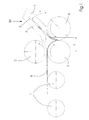
- a sheet 8 is shown, which is just between the folding rollers 3, 6, folded.
- the sheet was fed from the feed rollers 1 to the upper feed roller 2 and lower Feed roller 3, which also works as folding rollers 3, fed.
- the leading edge of the incoming arc 8 tilts down due to gravity G, but decreases the distance L from a projection of the Falztaschenunterseite 4 upwards in the Folder 20 headed.
- the folding pocket is at an angle ⁇ to the horizontal.
- the Sheet 8 slides along the Falztaschenunterseite 4 and Falztaschenoberseite 7 the Folding pocket 20 up, driven by the upper feed roller 2 and the lower Feeding roller 3 up to the stop 5.
- the resistance of the sheet 8 to the folding decreases and the weight G of the sheet part between the folding rollers 2, 3 and the folding pocket 20 increases as the distance L increases. For this reason, folding machines typically have a possibility of displacing the pocket position. As the thickness and density of the paper increase, the distance L is increased to reduce the sheet resistance, but with thin and soft paper, the distance L is reduced so that the sheet does not sag and crumple but runs normally into the pocket. As the inclination angle ⁇ of the folding pocket 20 increases, the resistances on the pocket wall N 4 and the frictional force F 4 increase . Consequently, the conditions of sheet introduction deteriorate in the pocket and the value of the resultant R decreases.
- the condition of the surface of the folding pocket 20 is very important, since it depends on the friction coefficient of the paper on the pocket and consequently also the value of the frictional force F 4 .
- the inclination angle ⁇ of the folding pocket 20 is mathematically chosen so that on the one hand, the resistance during insertion of the sheet 8 in the folding pocket 20 is not too large and on the other hand, the distribution of forces F 4 , G, N 4 , N 5 , P 2 , P 3rd as cheap as possible.
- the most common are inclination angles ⁇ of 30 ° to 45 °.
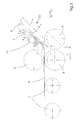
- such a Venturi nozzle 10 is located above the sheet 8, on the folding pocket upper side 7, and generates an air flow 31 which takes place substantially parallel to the sheet running direction.
- a force F B is generated by the air flow 31 by friction with the sheet top, which drives the sheet 8 in the direction of the stopper 5.
- the air flow 31 above the sheet 8 generates a pressure P o which is lower than the air pressure below the sheet P u .
- This negative pressure above the arc P o creates a suction that pulls the sheet 8 in the direction of the Falztaschenoberseite 7.
- the sheet 8 is also prevented by the air flow 31 at the same time to reach the Falztaschenoberseite 7. Accordingly, therefore, an air cushion between Falztaschenoberseite 7 and sheet 8, formed by the air flow 31.
- the sheet 8 is no longer in contact with the Falztascheunterseite 4, so that the friction force F 4 is considerably reduced at this point.
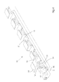
- FIG. 4 Such an arrangement of a plurality of blowing air nozzles 10 is shown in FIG. 4 shown.
- the nozzle bar 11 which are for example molded in one piece can, shown.
- the nozzle bar 11 consists of a plurality of nozzle bodies 12, the are arranged identical to each other next to each other and a common Blas Kunststoffzu effet 19th have blown through the air.
- a semicircular nozzle chamber 14 is arranged in the nozzle body 12 arranged.
- the semicircular nozzle chamber 14 tapers in height to the outlet opening 16 back.
- In the bottom of the nozzle chamber 14 is provided a connection with the Blas Kunststoffzu effet 19.
- the cover of the nozzle chamber 14 forms a separate plate 18, with suitable fasteners, for. Adhesive, is attached to the nozzle body 12.
- the separate plate 18 also forms at the same time a part of the outlet opening 16, through which an airflow 31 exits.
- such a nozzle bar 11 in each folding pocket 20 a Folding machine used.
- B. only the first folding pocket with a to equip such blower device 10.
- individual To provide nozzle body 12 side by side It is also conceivable, the outermost To design blowing air nozzles such that they have an additional laterally acting Have force components, which can additionally stabilize the sheet 8.
Landscapes
- Folding Of Thin Sheet-Like Materials, Special Discharging Devices, And Others (AREA)
- Air Bags (AREA)
- Details Of Garments (AREA)
- Sewing Machines And Sewing (AREA)
Abstract
Description
- Eine Gewichtskomponente, die sich aus der Schrägstellung der Falztasche und dem Flächengewicht des Bogens ergibt,
- Eine Reibungskomponenten, die sich aus der Reibung zwischen den Führungselementen, insbesondere dem unteren Führungselement, und dem Flächengewicht des Bogens ergibt. Diese Komponenten schließt Adhäsionskräfte ein.
- Eine Reibungskomponente, die sich durch elektrostatische Aufladung des Papierbogens während des Bogentransports und des Falzvorgangs ergibt.
- Bereitstellen einer Blasluftvorrichtung am Eingang einer Falztasche
- Erzeugen eines Luftstromes im Wesentlichen parallel zur Einlaufrichtung der Bogen in die Falztasche.
- Fig. 1
- das Falzprinzip einer Taschenfalzmaschine;
- Fig. 2
- Kräfte, die zur Bildung des Falzes auf den Bogen in der Falztasche einwirken sowie die vektorielle Darstellung dieser Kräfte;
- Fig. 3
- eine Falztasche mit der erfindungsgemäßen Blasvorrichtung;
- Fig. 4
- eine Ausführungsform mit einer Mehrzahl von nebeneinander angeordneten Blasluftdüsen.
- 1
- Förderwalze
- 2
- obere Zuführwalze
- 3
- untere Zuführwalze, Falzwalze
- 4
- Falztaschenunterseite
- 5
- Anschlag
- 6
- Falzwalze
- 7
- Falztaschenoberseite
- 8
- Bogen
- 10
- Blasluftvorrichtung
- 11
- Düsenbalken
- 12
- Düsenkörper
- 14
- Düsenkammer
- 16
- Austrittsöffnung
- 18
- Platte
- 19
- Blasluftzuleitung
- 20
- Falztasche
- 30
- Luftstrom
- 31
- Luftstrom aus der Blasluftdüse
- α
- Winkel der Falztasche
- F4
- Reibungskraft
- FB
- Blasluftkraft
- G
- Gewichtskraft
- L
- Entfernung zwischen Zuführwalzen und Tascheneingang
- N4
- Normalenkraft des Bogens in der Tasche
- N5
- Gegenkraft am Anschlag
- P2, P3
- Kraft der Zuführwalze 2 bzw. 3
- Po,u
- Luftdruck oberhalb, bzw. unterhalb des Bogens
- R
- Resultierende Kraft
Claims (15)
- Blasvorrichtung für eine Falztasche (20), mit wenigstens einer Blasluftdüse (12, 14, 16, 18)
dadurch gekennzeichnet, dass die wenigstens eine Blasluftdüse (12, 14, 16, 18) derart ausgestaltet ist, dass damit ein Luftstrom (31) erzeugbar ist, der im Wesentlichen in Einlaufrichtung der Falztasche (20) verläuft. - Blasvorrichtung nach Anspruch 1,
dadurch gekennzeichnet, dass die Blasluftdüse (12, 14, 16, 18) derart ausgestaltet ist, dass der Luftstrom (31) im Wesentlichen parallel zur Bewegungsrichtung eines einlaufenden Bogens (8) erfolgt. - Blasvorrichtung nach einem der Ansprüche 1 bis 2,
dadurch gekennzeichnet, dass es sich bei der Blasluftdüse (12, 14, 16, 18) um eine Venturidüse (12, 14, 16, 18) handelt. - Blasvorrichtung nach einem der Ansprüche 1 bis 3,
dadurch gekennzeichnet, dass die Blasluftdüse (12, 14, 16, 18) einen Düsenkörper (12) aufweist, wobei der Düsenkörper (12) eine Blasluftzuleitung (19) umfasst, durch die Blasluft in eine Düsenkammer (14) strömt, um durch eine schlitzförmige Austrittsöffnung (16) auszutreten. - Blasvorrichtung nach Anspruch 4,
dadurch gekennzeichnet, dass die Düsenkammer (14) im Wesentlichen halbkreisförmig ausgestaltet ist. - Blasvorrichtung nach einem der Ansprüche 4 bis 5,
dadurch gekennzeichnet, dass die Düsenkammer (14) zum Teil durch den Düsenkörper (12) und zum Teil durch eine separate Platte (18) gebildet wird, wobei die separate Platte (18) an dem Düsenkörper (12) befestigt ist, insbesondere angeklebt ist. - Blasvorrichtung nach Anspruch 6,
dadurch gekennzeichnet, dass die schlitzförmige Austrittsöffnung (18) zum Teil durch den Düsenkörper (12) und zum Teil durch die separate Platte (18) gebildet wird. - Blasvorrichtung nach einem der Ansprüche 4 bis 7,
dadurch gekennzeichnet, dass die Blasvorrichtung (10) einen Düsenbalken (11) aufweist, wobei der Düsenbalken (11) eine Mehrzahl an Düsenkörpern (12) umfasst. - Blasvorrichtung nach Anspruch 8,
dadurch gekennzeichnet, dass der Düsenbalken (11) einstückig abgeformt ist. - Blasvorrichtung nach einem der Ansprüche 1 bis 9,
dadurch gekennzeichnet, dass die Blasvorrichtung (10) in einer Falztasche (20) oberhalb des Transportpfades angebracht ist. - Blasvorrichtung nach einem der Ansprüche 1 bis 10,
dadurch gekennzeichnet, dass die Blasvorrichtung zur Ionisierung der Blasluft (31) mit der Blasvorrichtung (10) verbunden ist. - Blasvorrichtung nach einem der Ansprüche 1 bis 11,
dadurch gekennzeichnet, dass eine Mehrzahl an Blasluftdüsen (12, 14, 16, 18) quer zur Einlaufrichtung entlang einer Falztasche (20) angeordnet sind. - Verfahren zur Unterstützung von einlaufenden Bogen (8) in eine Falztasche (20) mit den Schritten:Bereitstellen einer Blasluftvorrichtung (10) am Eingang einer Falztasche (20)Erzeugen eines Luftstroms (31) im Wesentlichen parallel zur Einlaufrichtung der Bogen (8) in die Falztasche (20)
- Falztasche (20) mit einer Blasvorrichtung (10) gemäß einem der Ansprüche 1 bis 12.
- Falzmaschine mit einer Falztasche (20) gemäß Anspruch 14.
Applications Claiming Priority (2)
| Application Number | Priority Date | Filing Date | Title |
|---|---|---|---|
| DE102004012692 | 2004-03-16 | ||
| DE102004012692A DE102004012692A1 (de) | 2004-03-16 | 2004-03-16 | Blasvorrichtung für eine Falztasche |
Publications (2)
| Publication Number | Publication Date |
|---|---|
| EP1577244A1 true EP1577244A1 (de) | 2005-09-21 |
| EP1577244B1 EP1577244B1 (de) | 2008-04-30 |
Family
ID=34833127
Family Applications (1)
| Application Number | Title | Priority Date | Filing Date |
|---|---|---|---|
| EP05101033A Expired - Lifetime EP1577244B1 (de) | 2004-03-16 | 2005-02-11 | Blasvorrichtung für eine Falztasche |
Country Status (4)
| Country | Link |
|---|---|
| EP (1) | EP1577244B1 (de) |
| AT (1) | ATE393751T1 (de) |
| DE (2) | DE102004012692A1 (de) |
| PT (1) | PT1577244E (de) |
Cited By (1)
| Publication number | Priority date | Publication date | Assignee | Title |
|---|---|---|---|---|
| EP2517995A1 (de) * | 2011-04-28 | 2012-10-31 | Heidelberger Druckmaschinen AG | Falzmaschine mit Transportvorrichtung |
Families Citing this family (3)
| Publication number | Priority date | Publication date | Assignee | Title |
|---|---|---|---|---|
| DE102015213336A1 (de) | 2015-07-16 | 2017-01-19 | Heidelberger Druckmaschinen Ag | Taschenfalzwerk und Bogenfalzmaschine mit einem solchen Taschenfalzwerk |
| DE102015213334A1 (de) | 2015-07-16 | 2017-01-19 | Heidelberger Druckmaschinen Ag | Taschenfalzwerk und Bogenfalzmaschine mit einem solchen Taschenfalzwerk |
| DE102024137989B3 (de) * | 2024-12-16 | 2025-12-31 | Heidelberger Druckmaschinen Aktiengesellschaft | Verfahren zum Falzen von Bogen aus faserbasiertem Material in einer Falzmaschine |
Citations (3)
| Publication number | Priority date | Publication date | Assignee | Title |
|---|---|---|---|---|
| GB512869A (en) * | 1937-03-24 | 1939-09-27 | Ludolf Colditz | Improvements in and relating to buckle folding machines |
| DE8906505U1 (de) * | 1989-05-26 | 1989-08-03 | Stahl Gmbh & Co Maschinenfabrik, 7140 Ludwigsburg | Blasvorrichtung zur Unterstützung für den einlaufenden Bogen in einer Falztasche |
| DE10157082A1 (de) * | 2001-11-21 | 2003-05-28 | Hans Schwerdter | Zusatzeinrichtung für einen Bogenanlagetisch |
Family Cites Families (7)
| Publication number | Priority date | Publication date | Assignee | Title |
|---|---|---|---|---|
| DE1186473B (de) * | 1962-02-24 | 1965-02-04 | Planeta Veb Druckmasch Werke | Bogenanlege-Vorrichtung |
| DE7029693U (de) * | 1970-08-07 | 1971-04-29 | Erwin Schmidt Maschinenfabrik | Vorrichtung zum falzen von bogen, folien od. dgl. im fenster-. altar- oder zentralfalz. |
| NL7701431A (nl) * | 1976-03-08 | 1977-09-12 | Xerox Corp | Werkwijze voor het omkeren van de bewegings- richting van een blad. |
| DE2921008A1 (de) * | 1979-05-23 | 1980-11-27 | Siemens Ag | Einrichtung fuer den nahezu reibungsfreien transport von losem blattfoermigen material |
| JP2948465B2 (ja) * | 1994-01-14 | 1999-09-13 | 三田工業株式会社 | 用紙送り装置 |
| DE29615295U1 (de) * | 1996-09-03 | 1996-10-24 | Heidelberger Druckmaschinen Ag, 69115 Heidelberg | Vorrichtung zur berührungslosen Bogenführung in einer Bogendruckmaschine |
| DE10042888A1 (de) * | 2000-08-31 | 2002-03-14 | Heidelberger Druckmasch Ag | Bogenleiteinrichtung |
-
2004
- 2004-03-16 DE DE102004012692A patent/DE102004012692A1/de not_active Withdrawn
-
2005
- 2005-02-11 AT AT05101033T patent/ATE393751T1/de not_active IP Right Cessation
- 2005-02-11 EP EP05101033A patent/EP1577244B1/de not_active Expired - Lifetime
- 2005-02-11 PT PT05101033T patent/PT1577244E/pt unknown
- 2005-02-11 DE DE502005003887T patent/DE502005003887D1/de not_active Expired - Lifetime
Patent Citations (3)
| Publication number | Priority date | Publication date | Assignee | Title |
|---|---|---|---|---|
| GB512869A (en) * | 1937-03-24 | 1939-09-27 | Ludolf Colditz | Improvements in and relating to buckle folding machines |
| DE8906505U1 (de) * | 1989-05-26 | 1989-08-03 | Stahl Gmbh & Co Maschinenfabrik, 7140 Ludwigsburg | Blasvorrichtung zur Unterstützung für den einlaufenden Bogen in einer Falztasche |
| DE10157082A1 (de) * | 2001-11-21 | 2003-05-28 | Hans Schwerdter | Zusatzeinrichtung für einen Bogenanlagetisch |
Cited By (2)
| Publication number | Priority date | Publication date | Assignee | Title |
|---|---|---|---|---|
| EP2517995A1 (de) * | 2011-04-28 | 2012-10-31 | Heidelberger Druckmaschinen AG | Falzmaschine mit Transportvorrichtung |
| DE102011018859A1 (de) * | 2011-04-28 | 2012-10-31 | Heidelberger Druckmaschinen Aktiengesellschaft | Falzmaschine mit Transportvorrichtung |
Also Published As
| Publication number | Publication date |
|---|---|
| EP1577244B1 (de) | 2008-04-30 |
| DE102004012692A1 (de) | 2005-10-06 |
| DE502005003887D1 (de) | 2008-06-12 |
| PT1577244E (pt) | 2008-08-07 |
| ATE393751T1 (de) | 2008-05-15 |
Similar Documents
| Publication | Publication Date | Title |
|---|---|---|
| DE4242730C2 (de) | Bogenausleger einer Druckmaschine | |
| DE10213705B4 (de) | Vorrichtung zum Fördern eines Bogenstroms von einem Bogenstapel zu einer bogenverarbeitenden Maschine | |
| DE3914197C2 (de) | Vorrichtung zum Öffnen einer lose anliegenden Klappe von Briefumschlägen | |
| EP2517995B1 (de) | Falzmaschine mit Transportvorrichtung | |
| EP1914004A2 (de) | Verfahren zum Steuern eines Puderbestäubers | |
| EP0071769B1 (de) | Einrichtung in der Auslage von Bogenrotationsdruckmaschinen, um dem Einrollen der Bogenvorderkante entgegenzuwirken | |
| DE4424483C2 (de) | Ausleger einer bogenverarbeitenden Maschine | |
| DE19733692A1 (de) | Bogenausleger einer Druckmaschine | |
| EP1577244B1 (de) | Blasvorrichtung für eine Falztasche | |
| DE19537284C1 (de) | Bogenleiteinrichtung für Bogenanleger | |
| EP2727868B1 (de) | Vorrichtung und Verfahren zum Falzen von Druckbogen | |
| DE1231261B (de) | Vorrichtung zum aufeinanderfolgenden Austeilen von Schriftstuecken | |
| DE2749095A1 (de) | Vorrichtung zum oeffnen von druckprodukten | |
| DE69503407T2 (de) | Vorrichtung zur vereinzelten Ausgabe von Bogen von der Unterseite eines Stapels | |
| EP0062785B1 (de) | Vorrichtung zum Herauslösen von mittels eines Förderers geförderten, biegsamen, flächigen Erzeugnissen, insbesondere Druckprodukten, aus dem Förderstrom | |
| EP2086292B1 (de) | Verfahren und Vorrichtung zur elektrostatischen Entladung von mehrblättrigen Druckereiprodukten | |
| DE4012943C2 (de) | ||
| DE102010041453B4 (de) | Bogendruckmaschine mit einem Zuführtisch zum Fördern von Bogen in geschuppter Folge | |
| DE102005009048B4 (de) | Verfahren zur Verhinderung von unerwünschten Doppelfalzen und Blasvorrichtung für eine Falztasche | |
| EP3192757B1 (de) | Ablagevorrichtung für flache güter | |
| DE19515846C2 (de) | Schwebeelement zur Bogenführung in einer Druckmaschine oder dergleichen | |
| DD211771A1 (de) | Anleger zur kontinuierlichen zufuehrung von vereinzelten bogenlagen | |
| DE69110121T2 (de) | Zuführungs- und Abgabestruktur für Einzelblätter in einem Drucker. | |
| DE8906505U1 (de) | Blasvorrichtung zur Unterstützung für den einlaufenden Bogen in einer Falztasche | |
| EP1621495B1 (de) | Bogenanlage einer Bogendruckmaschine mit einer Bogenleiteinrichtung |
Legal Events
| Date | Code | Title | Description |
|---|---|---|---|
| PUAI | Public reference made under article 153(3) epc to a published international application that has entered the european phase |
Free format text: ORIGINAL CODE: 0009012 |
|
| AK | Designated contracting states |
Kind code of ref document: A1 Designated state(s): AT BE BG CH CY CZ DE DK EE ES FI FR GB GR HU IE IS IT LI LT LU MC NL PL PT RO SE SI SK TR |
|
| AX | Request for extension of the european patent |
Extension state: AL BA HR LV MK YU |
|
| 17P | Request for examination filed |
Effective date: 20060321 |
|
| AKX | Designation fees paid |
Designated state(s): AT BE BG CH CY CZ DE DK EE ES FI FR GB GR HU IE IS IT LI LT LU MC NL PL PT RO SE SI SK TR |
|
| 17Q | First examination report despatched |
Effective date: 20061026 |
|
| GRAP | Despatch of communication of intention to grant a patent |
Free format text: ORIGINAL CODE: EPIDOSNIGR1 |
|
| GRAS | Grant fee paid |
Free format text: ORIGINAL CODE: EPIDOSNIGR3 |
|
| GRAA | (expected) grant |
Free format text: ORIGINAL CODE: 0009210 |
|
| AK | Designated contracting states |
Kind code of ref document: B1 Designated state(s): AT BE BG CH CY CZ DE DK EE ES FI FR GB GR HU IE IS IT LI LT LU MC NL PL PT RO SE SI SK TR |
|
| REG | Reference to a national code |
Ref country code: GB Ref legal event code: FG4D Free format text: NOT ENGLISH |
|
| REG | Reference to a national code |
Ref country code: CH Ref legal event code: EP |
|
| REG | Reference to a national code |
Ref country code: IE Ref legal event code: FG4D Free format text: LANGUAGE OF EP DOCUMENT: GERMAN |
|
| REF | Corresponds to: |
Ref document number: 502005003887 Country of ref document: DE Date of ref document: 20080612 Kind code of ref document: P |
|
| REG | Reference to a national code |
Ref country code: PT Ref legal event code: SC4A Free format text: AVAILABILITY OF NATIONAL TRANSLATION Effective date: 20080728 |
|
| PG25 | Lapsed in a contracting state [announced via postgrant information from national office to epo] |
Ref country code: SI Free format text: LAPSE BECAUSE OF FAILURE TO SUBMIT A TRANSLATION OF THE DESCRIPTION OR TO PAY THE FEE WITHIN THE PRESCRIBED TIME-LIMIT Effective date: 20080430 |
|
| NLV1 | Nl: lapsed or annulled due to failure to fulfill the requirements of art. 29p and 29m of the patents act | ||
| PG25 | Lapsed in a contracting state [announced via postgrant information from national office to epo] |
Ref country code: NL Free format text: LAPSE BECAUSE OF FAILURE TO SUBMIT A TRANSLATION OF THE DESCRIPTION OR TO PAY THE FEE WITHIN THE PRESCRIBED TIME-LIMIT Effective date: 20080430 Ref country code: FI Free format text: LAPSE BECAUSE OF FAILURE TO SUBMIT A TRANSLATION OF THE DESCRIPTION OR TO PAY THE FEE WITHIN THE PRESCRIBED TIME-LIMIT Effective date: 20080430 Ref country code: ES Free format text: LAPSE BECAUSE OF FAILURE TO SUBMIT A TRANSLATION OF THE DESCRIPTION OR TO PAY THE FEE WITHIN THE PRESCRIBED TIME-LIMIT Effective date: 20080810 Ref country code: BG Free format text: LAPSE BECAUSE OF FAILURE TO SUBMIT A TRANSLATION OF THE DESCRIPTION OR TO PAY THE FEE WITHIN THE PRESCRIBED TIME-LIMIT Effective date: 20080730 |
|
| PG25 | Lapsed in a contracting state [announced via postgrant information from national office to epo] |
Ref country code: PL Free format text: LAPSE BECAUSE OF FAILURE TO SUBMIT A TRANSLATION OF THE DESCRIPTION OR TO PAY THE FEE WITHIN THE PRESCRIBED TIME-LIMIT Effective date: 20080430 |
|
| REG | Reference to a national code |
Ref country code: IE Ref legal event code: FD4D |
|
| PG25 | Lapsed in a contracting state [announced via postgrant information from national office to epo] |
Ref country code: IS Free format text: LAPSE BECAUSE OF FAILURE TO SUBMIT A TRANSLATION OF THE DESCRIPTION OR TO PAY THE FEE WITHIN THE PRESCRIBED TIME-LIMIT Effective date: 20080830 |
|
| PG25 | Lapsed in a contracting state [announced via postgrant information from national office to epo] |
Ref country code: LT Free format text: LAPSE BECAUSE OF FAILURE TO SUBMIT A TRANSLATION OF THE DESCRIPTION OR TO PAY THE FEE WITHIN THE PRESCRIBED TIME-LIMIT Effective date: 20080430 Ref country code: DK Free format text: LAPSE BECAUSE OF FAILURE TO SUBMIT A TRANSLATION OF THE DESCRIPTION OR TO PAY THE FEE WITHIN THE PRESCRIBED TIME-LIMIT Effective date: 20080430 Ref country code: SE Free format text: LAPSE BECAUSE OF FAILURE TO SUBMIT A TRANSLATION OF THE DESCRIPTION OR TO PAY THE FEE WITHIN THE PRESCRIBED TIME-LIMIT Effective date: 20080731 Ref country code: IE Free format text: LAPSE BECAUSE OF FAILURE TO SUBMIT A TRANSLATION OF THE DESCRIPTION OR TO PAY THE FEE WITHIN THE PRESCRIBED TIME-LIMIT Effective date: 20080430 Ref country code: CZ Free format text: LAPSE BECAUSE OF FAILURE TO SUBMIT A TRANSLATION OF THE DESCRIPTION OR TO PAY THE FEE WITHIN THE PRESCRIBED TIME-LIMIT Effective date: 20080430 |
|
| EN | Fr: translation not filed | ||
| PG25 | Lapsed in a contracting state [announced via postgrant information from national office to epo] |
Ref country code: SK Free format text: LAPSE BECAUSE OF FAILURE TO SUBMIT A TRANSLATION OF THE DESCRIPTION OR TO PAY THE FEE WITHIN THE PRESCRIBED TIME-LIMIT Effective date: 20080430 Ref country code: RO Free format text: LAPSE BECAUSE OF FAILURE TO SUBMIT A TRANSLATION OF THE DESCRIPTION OR TO PAY THE FEE WITHIN THE PRESCRIBED TIME-LIMIT Effective date: 20080430 |
|
| PLBE | No opposition filed within time limit |
Free format text: ORIGINAL CODE: 0009261 |
|
| STAA | Information on the status of an ep patent application or granted ep patent |
Free format text: STATUS: NO OPPOSITION FILED WITHIN TIME LIMIT |
|
| 26N | No opposition filed |
Effective date: 20090202 |
|
| PG25 | Lapsed in a contracting state [announced via postgrant information from national office to epo] |
Ref country code: FR Free format text: LAPSE BECAUSE OF FAILURE TO SUBMIT A TRANSLATION OF THE DESCRIPTION OR TO PAY THE FEE WITHIN THE PRESCRIBED TIME-LIMIT Effective date: 20090227 Ref country code: EE Free format text: LAPSE BECAUSE OF FAILURE TO SUBMIT A TRANSLATION OF THE DESCRIPTION OR TO PAY THE FEE WITHIN THE PRESCRIBED TIME-LIMIT Effective date: 20080430 |
|
| BERE | Be: lapsed |
Owner name: HEIDELBERGER DRUCKMASCHINEN A.G. Effective date: 20090228 |
|
| PG25 | Lapsed in a contracting state [announced via postgrant information from national office to epo] |
Ref country code: IT Free format text: LAPSE BECAUSE OF FAILURE TO SUBMIT A TRANSLATION OF THE DESCRIPTION OR TO PAY THE FEE WITHIN THE PRESCRIBED TIME-LIMIT Effective date: 20080430 |
|
| PG25 | Lapsed in a contracting state [announced via postgrant information from national office to epo] |
Ref country code: MC Free format text: LAPSE BECAUSE OF NON-PAYMENT OF DUE FEES Effective date: 20090228 |
|
| REG | Reference to a national code |
Ref country code: CH Ref legal event code: PL |
|
| GBPC | Gb: european patent ceased through non-payment of renewal fee |
Effective date: 20090211 |
|
| PG25 | Lapsed in a contracting state [announced via postgrant information from national office to epo] |
Ref country code: LI Free format text: LAPSE BECAUSE OF NON-PAYMENT OF DUE FEES Effective date: 20090228 Ref country code: CH Free format text: LAPSE BECAUSE OF NON-PAYMENT OF DUE FEES Effective date: 20090228 |
|
| PG25 | Lapsed in a contracting state [announced via postgrant information from national office to epo] |
Ref country code: BE Free format text: LAPSE BECAUSE OF NON-PAYMENT OF DUE FEES Effective date: 20090228 |
|
| PG25 | Lapsed in a contracting state [announced via postgrant information from national office to epo] |
Ref country code: GB Free format text: LAPSE BECAUSE OF NON-PAYMENT OF DUE FEES Effective date: 20090211 |
|
| PG25 | Lapsed in a contracting state [announced via postgrant information from national office to epo] |
Ref country code: AT Free format text: LAPSE BECAUSE OF NON-PAYMENT OF DUE FEES Effective date: 20090211 |
|
| PG25 | Lapsed in a contracting state [announced via postgrant information from national office to epo] |
Ref country code: GR Free format text: LAPSE BECAUSE OF FAILURE TO SUBMIT A TRANSLATION OF THE DESCRIPTION OR TO PAY THE FEE WITHIN THE PRESCRIBED TIME-LIMIT Effective date: 20080731 |
|
| PG25 | Lapsed in a contracting state [announced via postgrant information from national office to epo] |
Ref country code: LU Free format text: LAPSE BECAUSE OF NON-PAYMENT OF DUE FEES Effective date: 20090211 |
|
| PG25 | Lapsed in a contracting state [announced via postgrant information from national office to epo] |
Ref country code: HU Free format text: LAPSE BECAUSE OF FAILURE TO SUBMIT A TRANSLATION OF THE DESCRIPTION OR TO PAY THE FEE WITHIN THE PRESCRIBED TIME-LIMIT Effective date: 20081101 |
|
| PG25 | Lapsed in a contracting state [announced via postgrant information from national office to epo] |
Ref country code: TR Free format text: LAPSE BECAUSE OF FAILURE TO SUBMIT A TRANSLATION OF THE DESCRIPTION OR TO PAY THE FEE WITHIN THE PRESCRIBED TIME-LIMIT Effective date: 20080430 |
|
| PG25 | Lapsed in a contracting state [announced via postgrant information from national office to epo] |
Ref country code: CY Free format text: LAPSE BECAUSE OF FAILURE TO SUBMIT A TRANSLATION OF THE DESCRIPTION OR TO PAY THE FEE WITHIN THE PRESCRIBED TIME-LIMIT Effective date: 20080430 |
|
| PGFP | Annual fee paid to national office [announced via postgrant information from national office to epo] |
Ref country code: PT Payment date: 20140124 Year of fee payment: 10 |
|
| REG | Reference to a national code |
Ref country code: PT Ref legal event code: MM4A Free format text: LAPSE DUE TO NON-PAYMENT OF FEES Effective date: 20150811 |
|
| PG25 | Lapsed in a contracting state [announced via postgrant information from national office to epo] |
Ref country code: PT Free format text: LAPSE BECAUSE OF NON-PAYMENT OF DUE FEES Effective date: 20150811 |
|
| PGFP | Annual fee paid to national office [announced via postgrant information from national office to epo] |
Ref country code: DE Payment date: 20230228 Year of fee payment: 19 |
|
| P01 | Opt-out of the competence of the unified patent court (upc) registered |
Effective date: 20230425 |
|
| REG | Reference to a national code |
Ref country code: DE Ref legal event code: R119 Ref document number: 502005003887 Country of ref document: DE |
|
| PG25 | Lapsed in a contracting state [announced via postgrant information from national office to epo] |
Ref country code: DE Free format text: LAPSE BECAUSE OF NON-PAYMENT OF DUE FEES Effective date: 20240903 |
|
| PG25 | Lapsed in a contracting state [announced via postgrant information from national office to epo] |
Ref country code: DE Free format text: LAPSE BECAUSE OF NON-PAYMENT OF DUE FEES Effective date: 20240903 |