EP1575329A2 - Microphone à col de cygne avec fixation à tête sphérique - Google Patents
Microphone à col de cygne avec fixation à tête sphérique Download PDFInfo
- Publication number
- EP1575329A2 EP1575329A2 EP05101730A EP05101730A EP1575329A2 EP 1575329 A2 EP1575329 A2 EP 1575329A2 EP 05101730 A EP05101730 A EP 05101730A EP 05101730 A EP05101730 A EP 05101730A EP 1575329 A2 EP1575329 A2 EP 1575329A2
- Authority
- EP
- European Patent Office
- Prior art keywords
- microphone
- ball
- gooseneck
- attached
- pivoting
- Prior art date
- Legal status (The legal status is an assumption and is not a legal conclusion. Google has not performed a legal analysis and makes no representation as to the accuracy of the status listed.)
- Ceased
Links
Images
Classifications
-
- H—ELECTRICITY
- H04—ELECTRIC COMMUNICATION TECHNIQUE
- H04R—LOUDSPEAKERS, MICROPHONES, GRAMOPHONE PICK-UPS OR LIKE ACOUSTIC ELECTROMECHANICAL TRANSDUCERS; ELECTRIC HEARING AIDS; PUBLIC ADDRESS SYSTEMS
- H04R1/00—Details of transducers, loudspeakers or microphones
- H04R1/08—Mouthpieces; Microphones; Attachments therefor
Definitions
- the invention is based on a so-called gooseneck microphone according to the preamble of the independent claim.
- So-called gooseneck microphones are characterized by the fact that the actual Microphone is attached to a plastically deformable rod-shaped retaining element which in turn is rigidly attached to a console.
- the deformability of the Holding member serves to the microphone by bending the retaining element in a desired position, preferably near the mouth of the user to pivot.
- the Retaining element has sufficient stability, the microphone after its To keep pivoting in the pivoted position.
- Such gooseneck microphones For example, for handsfree for mobile phones in Motor vehicles or used for the announcement mode in travel or city buses.
- the gooseneck microphone according to the invention with the features of the independent Claim has the advantage of further degrees of freedom and in particular a larger Pivoting range when adjusting the microphone position.
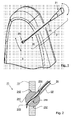
- Figure 1 shows the rear view of remindeulehneines vehicle seat 1, here for example the driver's seat in a motor vehicle.
- a Gooseneck microphone 2 is attached by means of a ball head bearing 21.
- the Gooseneck microphone 2 comprises on the one hand the actual microphone capsule 23, for another a plastically deformable hollow rod-shaped holding element 22, on which the Microphone 23 is attached.
- the holding element 22 itself and thus the Gooseneck microphone 2 is in turn by means of ball bearing 21 at the Backrest 1 attached.
- the ball bearing 21 causes the entire gooseneck microphone 2 in a partially, almost hemispherical space vertically upwards, or to the side is pivotable.
- the almost arbitrary deformability of the Gooseneck 22 and holding element 22 result for the position of the actual Microphone capsule 23 a variety of possible positions.
- that can Microphone 2 as indicated in the drawing by means of ball bearing 21 and Deformability of the retaining element 22 can be adjusted so that it is in front of the mouth of a comes to hold on the vehicle seat person.
- the ball-bearing 21 is formed so that the friction torque generated by it sufficient to adjust the microphone position due to vibration, as in the case of Driving on uneven floors or by running riot of a vehicle internal combustion engine etc. emerge, sure to prevent.
- the friction torque of the On the other hand, however, ball joint 21 is also set so low that the microphone 23 can be manually pivoted about the ball joint 21.
- the friction torque of the Ball joint 21 can be adjusted so that a pivoting of the Gooseneck microphone in a horizontal plane comparatively light, in one vertical level, however, is made possible with a comparatively higher moment.
- the is based on the consideration that vibrations of the microphone 2 due to the Gravity mainly exercise vertical forces on the arrangement, therefore, the Frictional torque must be high for pivoting the microphone 2 in the vertical direction, on the other hand, horizontal forces are comparatively low and consequently a lower friction torque in the horizontal direction is required to the microphone 2 in to hold the current position.
- This is further based on the consideration that For example, in the case of the impact of the vehicle on an obstacle, the microphone. 2 a thereby thrown in the direction of travel head of the user as possible low resistance to avoid injury.
- Figure 2 shows an advantageous embodiment of the ball joint 21.
- This includes first as a central part of a ball 211, attached to the gooseneck 22 is.
- the gooseneck 22 is in a cylindrical blind bore 215th taken up the ball 211 and glued, for example, or by means of a on the Outside of the gooseneck 22 threaded in this area screwed.
- the ball 211 is held in a bearing ring 212 which is connected to a Flange plate 11 is attached to the side of the vehicle seat.
- the flange plate may e.g. be welded to the tubular frame of the seat.
- the bearing ring 212 may preferably be made a wear-resistant material, in particular, for example, metal or a made of wear-resistant plastic and on the backrest 1 of the vehicle seat be used. Bearing ring 212 and ball 211 together form the ball joint 21 and Ball Head Bearing 21. Diameter of bearing ring 212 and ball head 211 are such adapted to each other, that a desired friction torque for rotation of the ball 211st is reached.
- the bearing ring may preferably be slightly out of round be formed, so that a pivoting of the ball in a vertical plane, in the drawing in the leaf level, a higher friction torque opposes, than at Swiveling in a horizontal, in the drawing perpendicular to the sheet standing level.
- the ball 211 has a further aligned with the blind bore 215, opposite to the Sack bore thinner hole 213 through which passes through the interior 214 of the Gooseneck 22 guided cable 24 of the microphone 23 are guided into the interior of the seat. From There, the cables 24 are further guided to a signal processing, not shown.
- the degrees of freedom by which the ball 211 can be pivoted are by the Retaining element 22 limited, are formed for the stops in the bearing ring.
- the mentioned Stops or the Verschwenkungsbegrenzung for the gooseneck 22 causes zuatzlich advantageously a shearing protection for the cable 24 of the microphone 23rd
Landscapes
- Physics & Mathematics (AREA)
- Engineering & Computer Science (AREA)
- Acoustics & Sound (AREA)
- Signal Processing (AREA)
- Fittings On The Vehicle Exterior For Carrying Loads, And Devices For Holding Or Mounting Articles (AREA)
- Details Of Audible-Bandwidth Transducers (AREA)
- Pivots And Pivotal Connections (AREA)
Applications Claiming Priority (2)
| Application Number | Priority Date | Filing Date | Title |
|---|---|---|---|
| DE102004011590 | 2004-03-10 | ||
| DE102004011590 | 2004-03-10 |
Publications (2)
| Publication Number | Publication Date |
|---|---|
| EP1575329A2 true EP1575329A2 (fr) | 2005-09-14 |
| EP1575329A3 EP1575329A3 (fr) | 2008-02-27 |
Family
ID=34813632
Family Applications (1)
| Application Number | Title | Priority Date | Filing Date |
|---|---|---|---|
| EP05101730A Ceased EP1575329A3 (fr) | 2004-03-10 | 2005-03-07 | Microphone à col de cygne avec fixation à tête sphérique |
Country Status (2)
| Country | Link |
|---|---|
| EP (1) | EP1575329A3 (fr) |
| DE (2) | DE102004024998A1 (fr) |
Families Citing this family (1)
| Publication number | Priority date | Publication date | Assignee | Title |
|---|---|---|---|---|
| DE102007023720B4 (de) | 2007-05-22 | 2019-05-09 | Bayerische Motoren Werke Aktiengesellschaft | Messeinrichtung mit mehreren Mikrofonen zur Anpassung und/oder Überprüfung einer Schall abgebenden Einrichtung |
Family Cites Families (10)
| Publication number | Priority date | Publication date | Assignee | Title |
|---|---|---|---|---|
| GB1040800A (en) * | 1964-10-09 | 1966-09-01 | Austin Motor Co Ltd | Motor vehicle sun visors |
| DE1802033A1 (de) * | 1968-10-09 | 1970-04-23 | Skf Kugellagerfabriken Gmbh | Anordnung zur Erzeugung unterschiedlicher Reibung und Daempfung von Lagern und Gelenken bei Bewegung um verschiedene Achsen |
| DE2727429C3 (de) * | 1977-06-18 | 1987-01-22 | TRW Ehrenreich GmbH & Co KG, 4000 Düsseldorf | Kugelgelenk für Kraftfahrzeuge |
| US4222680A (en) * | 1978-03-06 | 1980-09-16 | Browning Charles E | Variable position friction joint |
| DE2913700A1 (de) * | 1979-04-05 | 1980-10-09 | Ehrenreich Gmbh & Co Kg A | Kugelgelenk fuer die lenkung |
| SE9302878L (sv) * | 1993-09-03 | 1995-03-04 | Volvo Ab | Anordning vid mobiltelefon |
| CA2146283A1 (fr) * | 1995-04-04 | 1996-10-05 | Roger Alexander Hamblen | Support de microphone |
| US5771303A (en) * | 1995-05-25 | 1998-06-23 | Mazzarella; Charles W. | Microphone mounting and control system |
| US5805709A (en) * | 1997-04-25 | 1998-09-08 | Liou; I-Chang | Desktop microphone base |
| JP3905223B2 (ja) * | 1998-05-26 | 2007-04-18 | 株式会社オーディオテクニカ | マイクロホンスタンド |
-
2004
- 2004-05-21 DE DE102004024998A patent/DE102004024998A1/de not_active Withdrawn
- 2004-05-21 DE DE102004024997A patent/DE102004024997A1/de not_active Withdrawn
-
2005
- 2005-03-07 EP EP05101730A patent/EP1575329A3/fr not_active Ceased
Also Published As
| Publication number | Publication date |
|---|---|
| DE102004024998A1 (de) | 2005-09-29 |
| DE102004024997A1 (de) | 2005-09-29 |
| EP1575329A3 (fr) | 2008-02-27 |
Similar Documents
| Publication | Publication Date | Title |
|---|---|---|
| DE60125992T2 (de) | Zubehörhalter in kabine | |
| DE19922282B4 (de) | Befestigungseinrichtung für Innenraumsensoren | |
| DE10060624B4 (de) | Balancesystem für handgeführte Kameras | |
| DE102011017240A1 (de) | Befestigungsanordnung einer Außenkamera an einem Verkleidungsteil eines Kraftwagens | |
| EP2144435A2 (fr) | Caméra et boîtier de caméra | |
| DE102023005260B4 (de) | Haltevorrichtung für eine Anzeigeeinheit | |
| DE19814712A1 (de) | Elektrisch verstellbarer Außenrückspiegel | |
| DE102010054039A1 (de) | Manuell einziehbarer Fahrzeugtürspiegel | |
| EP1575329A2 (fr) | Microphone à col de cygne avec fixation à tête sphérique | |
| EP2208641B1 (fr) | Entraînement pour un composant qui est à ajuster | |
| DE4341952B4 (de) | Fahrzeugsitz mit einer ganz oder teilweise klappbaren Rückenlehne | |
| WO2002086383A1 (fr) | Projecteur comportant un boitier pourvu de griffes de retenue | |
| DE29706838U1 (de) | Halterung für Gegenstände in Fahrzeugen | |
| DE202009001838U1 (de) | Überwachungseinrichtung für ein Kraftfahrzeug zur Beobachtung des Verkehrs | |
| DE10139037C1 (de) | Haltevorrichtung für einen Gurtroller | |
| DE102020111745B4 (de) | Rückblickvorrichtung für ein Neigefahrzeug | |
| DE1780669C3 (de) | Fahrzeugrückblickspiegel | |
| DE10003917B4 (de) | Haltevorrichtung für eine Zierfigur eines Kraftfahrzeuges | |
| DE1758511U (de) | Windschluepfiger aussen-rueckblickspiegel fuer land-, luft- und wasserfahrzeuge. | |
| DE10163710B4 (de) | Tür für einen Personenkraftwagen mit einer Karosserie und mindestens zwei Türen | |
| EP2942235B1 (fr) | Système d'orientation destiné à l'inclinaison d'un système de vision indirect et système de vision indirect associé | |
| DE102012019640B4 (de) | Anordnung zur Befestigung eines Außenspiegels an einem Fahrzeug, Außenspiegel dazu sowie Fahrzeug mit einem derartigen Außenspiegel | |
| EP2568103A1 (fr) | Charnière continue | |
| DE102010060865A1 (de) | Pneumatische Feder-Dämpfer-Einheit mit einem im Zylindergehäuse verschiebbaren Kolben mit Kolbenstange | |
| DE3336795A1 (de) | Spiegelhalter |
Legal Events
| Date | Code | Title | Description |
|---|---|---|---|
| PUAI | Public reference made under article 153(3) epc to a published international application that has entered the european phase |
Free format text: ORIGINAL CODE: 0009012 |
|
| AK | Designated contracting states |
Kind code of ref document: A2 Designated state(s): AT BE BG CH CY CZ DE DK EE ES FI FR GB GR HU IE IS IT LI LT LU MC NL PL PT RO SE SI SK TR |
|
| AX | Request for extension of the european patent |
Extension state: AL BA HR LV MK YU |
|
| PUAL | Search report despatched |
Free format text: ORIGINAL CODE: 0009013 |
|
| AK | Designated contracting states |
Kind code of ref document: A3 Designated state(s): AT BE BG CH CY CZ DE DK EE ES FI FR GB GR HU IE IS IT LI LT LU MC NL PL PT RO SE SI SK TR |
|
| AX | Request for extension of the european patent |
Extension state: AL BA HR LV MK YU |
|
| 17P | Request for examination filed |
Effective date: 20080827 |
|
| 17Q | First examination report despatched |
Effective date: 20081001 |
|
| AKX | Designation fees paid |
Designated state(s): AT BE BG CH CY CZ DE DK EE ES FI FR GB GR HU IE IS IT LI LT LU MC NL PL PT RO SE SI SK TR |
|
| STAA | Information on the status of an ep patent application or granted ep patent |
Free format text: STATUS: THE APPLICATION HAS BEEN REFUSED |
|
| 18R | Application refused |
Effective date: 20090509 |