EP1574679A2 - Ventilhubsteuerungseinrichtung in einem Brennkraftmaschine und Verfahren - Google Patents
Ventilhubsteuerungseinrichtung in einem Brennkraftmaschine und Verfahren Download PDFInfo
- Publication number
- EP1574679A2 EP1574679A2 EP05002594A EP05002594A EP1574679A2 EP 1574679 A2 EP1574679 A2 EP 1574679A2 EP 05002594 A EP05002594 A EP 05002594A EP 05002594 A EP05002594 A EP 05002594A EP 1574679 A2 EP1574679 A2 EP 1574679A2
- Authority
- EP
- European Patent Office
- Prior art keywords
- rocker arm
- eccentric bush
- valve
- cam
- lift amount
- Prior art date
- Legal status (The legal status is an assumption and is not a legal conclusion. Google has not performed a legal analysis and makes no representation as to the accuracy of the status listed.)
- Withdrawn
Links
- 230000007246 mechanism Effects 0.000 title claims description 39
- 238000002485 combustion reaction Methods 0.000 title claims description 12
- 238000000034 method Methods 0.000 title description 3
- 230000002093 peripheral effect Effects 0.000 claims abstract description 45
- 230000008878 coupling Effects 0.000 claims description 10
- 238000010168 coupling process Methods 0.000 claims description 10
- 238000005859 coupling reaction Methods 0.000 claims description 10
- 239000011435 rock Substances 0.000 claims description 8
- 238000010586 diagram Methods 0.000 description 3
- 238000001514 detection method Methods 0.000 description 2
- 239000000463 material Substances 0.000 description 1
- 238000012986 modification Methods 0.000 description 1
- 230000004048 modification Effects 0.000 description 1
- XLYOFNOQVPJJNP-UHFFFAOYSA-N water Substances O XLYOFNOQVPJJNP-UHFFFAOYSA-N 0.000 description 1
Images



Classifications
-
- F—MECHANICAL ENGINEERING; LIGHTING; HEATING; WEAPONS; BLASTING
- F01—MACHINES OR ENGINES IN GENERAL; ENGINE PLANTS IN GENERAL; STEAM ENGINES
- F01L—CYCLICALLY OPERATING VALVES FOR MACHINES OR ENGINES
- F01L13/00—Modifications of valve-gear to facilitate reversing, braking, starting, changing compression ratio, or other specific operations
- F01L13/0015—Modifications of valve-gear to facilitate reversing, braking, starting, changing compression ratio, or other specific operations for optimising engine performances by modifying valve lift according to various working parameters, e.g. rotational speed, load, torque
- F01L13/0021—Modifications of valve-gear to facilitate reversing, braking, starting, changing compression ratio, or other specific operations for optimising engine performances by modifying valve lift according to various working parameters, e.g. rotational speed, load, torque by modification of rocker arm ratio
-
- F—MECHANICAL ENGINEERING; LIGHTING; HEATING; WEAPONS; BLASTING
- F01—MACHINES OR ENGINES IN GENERAL; ENGINE PLANTS IN GENERAL; STEAM ENGINES
- F01L—CYCLICALLY OPERATING VALVES FOR MACHINES OR ENGINES
- F01L13/00—Modifications of valve-gear to facilitate reversing, braking, starting, changing compression ratio, or other specific operations
- F01L13/0015—Modifications of valve-gear to facilitate reversing, braking, starting, changing compression ratio, or other specific operations for optimising engine performances by modifying valve lift according to various working parameters, e.g. rotational speed, load, torque
- F01L13/0021—Modifications of valve-gear to facilitate reversing, braking, starting, changing compression ratio, or other specific operations for optimising engine performances by modifying valve lift according to various working parameters, e.g. rotational speed, load, torque by modification of rocker arm ratio
- F01L13/0026—Modifications of valve-gear to facilitate reversing, braking, starting, changing compression ratio, or other specific operations for optimising engine performances by modifying valve lift according to various working parameters, e.g. rotational speed, load, torque by modification of rocker arm ratio by means of an eccentric
-
- F—MECHANICAL ENGINEERING; LIGHTING; HEATING; WEAPONS; BLASTING
- F01—MACHINES OR ENGINES IN GENERAL; ENGINE PLANTS IN GENERAL; STEAM ENGINES
- F01L—CYCLICALLY OPERATING VALVES FOR MACHINES OR ENGINES
- F01L1/00—Valve-gear or valve arrangements, e.g. lift-valve gear
- F01L1/12—Transmitting gear between valve drive and valve
- F01L1/14—Tappets; Push rods
- F01L1/143—Tappets; Push rods for use with overhead camshafts
-
- F—MECHANICAL ENGINEERING; LIGHTING; HEATING; WEAPONS; BLASTING
- F01—MACHINES OR ENGINES IN GENERAL; ENGINE PLANTS IN GENERAL; STEAM ENGINES
- F01L—CYCLICALLY OPERATING VALVES FOR MACHINES OR ENGINES
- F01L13/00—Modifications of valve-gear to facilitate reversing, braking, starting, changing compression ratio, or other specific operations
- F01L13/0015—Modifications of valve-gear to facilitate reversing, braking, starting, changing compression ratio, or other specific operations for optimising engine performances by modifying valve lift according to various working parameters, e.g. rotational speed, load, torque
- F01L13/0063—Modifications of valve-gear to facilitate reversing, braking, starting, changing compression ratio, or other specific operations for optimising engine performances by modifying valve lift according to various working parameters, e.g. rotational speed, load, torque by modification of cam contact point by displacing an intermediate lever or wedge-shaped intermediate element, e.g. Tourtelot
- F01L2013/0073—Modifications of valve-gear to facilitate reversing, braking, starting, changing compression ratio, or other specific operations for optimising engine performances by modifying valve lift according to various working parameters, e.g. rotational speed, load, torque by modification of cam contact point by displacing an intermediate lever or wedge-shaped intermediate element, e.g. Tourtelot with an oscillating cam acting on the valve of the "Delphi" type
-
- F—MECHANICAL ENGINEERING; LIGHTING; HEATING; WEAPONS; BLASTING
- F01—MACHINES OR ENGINES IN GENERAL; ENGINE PLANTS IN GENERAL; STEAM ENGINES
- F01L—CYCLICALLY OPERATING VALVES FOR MACHINES OR ENGINES
- F01L2303/00—Manufacturing of components used in valve arrangements
Definitions
- the present invention relates to an adjusting mechanism and an adjusting method of a valve-lift amount of an internal combustion engine for rocking a rocker arm when a camshaft is rotated and for rocking a rocking cam provided on the camshaft to open and close a valve.
- valve operating mechanism which variably controls a valve-lift amount corresponding to variation of an engine operating state as disclosed in Japanese Patent Applications Laid-open Nos. 2002-221014 and H11-107725.
- a rocking cam opens and closes a suction valve by a rotation force transmitted, through a rocker arm or a link member, from a drive cam which is an eccentric rotation cam provided on a camshaft.
- the valve operating mechanism controls rotation of a control cam on an outer periphery of a control shaft disposed in parallel to the camshaft and changes a rocking fulcrum of the rocker arm, thereby varying the valve-lift amount corresponding to the engine operating state.
- valve-lift amount is determined by size precision of link parts, the valve-lift amounts are varied between cylinders depending upon the size precision.
- it is necessary that the valve-lift amount is measured in a state where the valve operating mechanism is assembled and then the valve operating mechanism is disassembled and a link member is replaced by another link member having different length, and this deteriorates the operation efficiency.
- the present invention has been achieved in order to solve the above problem, and it is an object of the invention to provide an adjusting mechanism and an adjusting method of a valve-lift amount for easily adjusting the valve-lift amount.
- the present invention provides a valve-lift amount adjusting mechanism of an internal combustion engine in which a rocker arm is rocked with respect to a rocking support shaft when a camshaft rotates, a rocking cam provided on the camshaft is rocked when the rocker arm rocks, thereby opening and closing a valve, wherein the rocker arm is rockably supported with respect to the rocking support shaft through an eccentric bush, a coupling portion is provided between the eccentric bush and the rocker arm, the coupling portion can switch between a state where the eccentric bush and the rocker arm can integrally rock with respect to the rocking support shaft and a state where the eccentric bush and the rocker arm can relatively rotate.
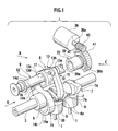
- Fig. 1 is a perspective view of a valve operating mechanism having a valve-lift amount adjusting mechanism of an internal combustion engine according to an embodiment of the invention, when the valve-lift amount of the valve operating mechanism is adjusted.
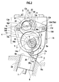
- Fig. 2 is a sectional view taken along an arrow A in Fig. 1.
- the valve operating mechanism is applied to a suction side of the engine.
- the valve operating mechanism includes two suction valves 1 for each cylinder, and variable valve operating mechanisms. Each variable valve operating mechanism varies a valve-lift amount of each suction valve 1 corresponding to an engine operating state.
- each of the variable valve operating mechanisms includes the pair of suction valves 1 which are slidably provided on a cylinder head 2 through valve guides and which are biased in their closing direction by spring force of a valve spring, a drive shaft 3 as a hollow camshaft rotatably supported by a bearing 4 provided at an upper portion of the cylinder head 2, a drive cam 5 which is an eccentric rotation cam fixed to the drive shaft 3, a rocking cam 7 which is rockably supported by an outer periphery of the drive shaft 3 and which comes into slide contact with an upper surface 6a of a valve lifter 6 disposed on an upper end of each suction valve 1, a transmitting mechanism 8 which is associated between the drive cam 5 and the rocking cam 7 for transmitting rotation force of the drive cam 5 as a rocking force of the rocking cam 7, and a control mechanism 9 which controls an operation position of the transmitting mechanism 8.
- the drive shaft 3 is disposed along a longitudinal direction of the engine.
- the rotation force is transmitted to the drive shaft 3 from a crankshaft of the engine through a follower sprocket (not shown) provided on one end of the drive shaft 3 and a timing chain wound around the follower sprocket.
- the rotation direction is the counterclockwise direction (direction shown with an arrow in Fig. 2).
- the drive cam 5 is made of wear resistant material and formed into substantially cylindrical shape. As shown in Fig. 2, a drive shaft-inserting hole 5a is formed in the drive cam 5 such as to penetrate the drive cam 5 in its axial direction. A center of the drive shaft-inserting hole 5a is deviated from an axis X of the drive shaft 3 in a radial direction by a predetermined amount ⁇ .
- the drive cam 5 is fixed to the drive shaft 3, and as the drive shaft 3 rotates, the drive cam 5 rotates in the counterclockwise direction in Fig. 2.
- Thevalve lifter 6 is formed into a bottomed cylindrical shape, and is slidably held in a holding hole 2a of the cylinder head 2.
- the upper surface 6a of the valve lifter 6 is formed flatly. Later-described cam bodies 7a of the rocking cams 7 come into slide contact with the upper surface 6a.
- the rocking cams 7 respectively have cam bodies 7a.
- the cam bodies 7a are integrally provided on both ends of a cylindrical base 10 .
- Each cam body 7a is formed into a raindrop shape.
- a support hole is formed in the base 10 in its axial direction.
- the entire drive shaft 3 is inserted into the support hole and is rockably supported therein.
- One of the two rocking cams 7 is formed at its one end with a cam nose 11, and a pin hole 11a is formed in the cam nose 11 such as to penetrate the cam nose 11.
- a cam face formed on a lower surface of each cam body 7a abuts against a predetermined position of the upper surface 6a of each valve lifter 6, thereby varying valve lift characteristics.
- the transmitting mechanism 8 includes a rocker arm 13 disposed above the drive shaft 3, a link arm 14 which connects one end 13a of the rocker arm 13 and the drive cam 5 to each other, and a link member 15 which connects the other end 13b of the rocker arm 13 and the rocking cam 7 to each other.
- the rocker arm 13 is provided at its center with a cylindrical base portion 13c.
- the cylindrical base portion 13c and a later-described eccentric bush 22 are integrally coupled to each other and are rotatably supported by a control cam 23 as an eccentric cam.
- the cylindrical base portion 13c formed at the center of the rocker arm 13 includes a support hole 13d.
- the eccentric bush 22 is fixed and coupled to the support hole 13d (this coupled state is released in Fig. 1) and in this state, the rocker arm 13 is rockably supported integrally with the eccentric bush 22 with respect to a control cam 23 of a control shaft 32 as a later-described rocking support shaft.
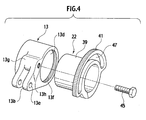
- Figs. 3 and 4 are exploded perspective views of the rocker arm 13 and the eccentric bush 22.
- Fig. 3 shows the state as viewed from an arrow B in Fig. 1
- Fig. 4 shows the state as viewed from an arrow C in Fig. 1.
- the one end 13a projects from one outer end of the cylindrical base portion 13c of the rocker arm 13.
- the one end 13a is provided with a pin 16.
- the pin 16 is rotatably inserted into and connected to a through hole 14d formed in an end of the link arm 14.
- the other end 13b projects from the other outer side of the cylindrical base portion 13c.
- the other end 13b is formed with a through hole 13e.
- a connection pin 17 is inserted into the through hole 13e and a through hole 15a formed in an end of the link member 15, and the rocker arm 13 and the link member 15 are rotatably connected to each other.
- the link arm 14 shown in Figs. 1 and 2 includes a base 14a which is an annular one end having relatively large diameter, and a projecting end 14b which is the other end projecting from a predetermined position of an outer peripheral surface of the base 14a.
- a fitting hole 14c is formed in a central position of the base 14a.
- the fitting hole 14c is rotatably fitted over an outer peripheral surface of the drive cam 5.
- the pin hole 14d is formed in the projecting end 14b.
- the pin 16 is rotatably inserted into the pin hole 14d.
- An axis 16a of the pin 16 functions as a pivot point of the one end 13a of the rocker arm 13.
- Both ends 15b and 15c of the link member 15 are respectively rotatably connected to the other end 13b of the rocker arm 13 and the cam nose 11 of the cam body 7a through the connection pin 17 and a connection pin 30.
- connection pins 17 and 30 serve as pivot points of both ends 15b and 15c of the link member 15, the other end 13b of the rocker arm 13 and the cam nose 11 of the rocking cam 7.
- the control mechanism 9 includes a control shaft 32 which extends in parallel to the drive shaft 3 above the drive shaft 3 and in a longitudinal direction of the engine and which is rotatably supported by the bearing 4, the control cam 23 which serves as the rocking fulcrum of the rocker arm 13, a DC motor which controls the rotation of the control shaft 32 through a ball screw mechanism or a gear (both not shown) , and a controller which controls the operation of the DC motor.
- An axis of the control cam 23 is deviated from an axis of the control shaft 32 by a predetermined amount, and with this configuration, the valve-lift amount is variably controlled corresponding to variation of the engine operating state.
- the eccentric bush 22 is inserted into the support hole 13d of the rocker arm 13, and the position of an axis P2 of an outer peripheral circle of the eccentric bush 22 is deviated from an axis P1 (axis of an inner peripheral circle of the eccentric bush 22) by an amount ⁇ corresponding to a thick portion 39a.
- the eccentric bush 22 includes a cylindrical portion 39 which is rotatably inserted into the control cam 23 of the control shaft 32 at its inner peripheral circle.
- the eccentric bush 22 can rock integrally with the rocker arm 13.
- the eccentric bush 22 can move in the axial direction with respect to the control cam 23 and the rocker arm 13.
- the cylindrical portion 39 is provided at its portion in the circumferential direction with the thick portion 39a.
- the cylindrical portion 39 is provided at its one end of the outer peripheral portion with an outer peripheral gear 39b over the entire circumference.
- an inner peripheral gear 13f is provided at one end of an inner surface of the support hole 13d of the rocker arm 13 over the entire circumference. If the cylindrical portion 39 of the eccentric bush 22 is inserted into the support hole 13d of the rocker arm 13, the outer peripheral gear 39b and the inner peripheral gear 13f mesh each other and couple to each other. That is, the outer peripheral gear 39b and the inner peripheral gear 13f constitute a coupling portion capable of switching between a state where the eccentric bush 22 and the rocker arm 13 can integrally rock and a state where the eccentric bush 22 and the rocker arm 13 can relatively rotate.
- a driving gear 41 having a larger diameter than that of the cylindrical portion 39 is provided at a position of the cylindrical portion 39 closer to its end than the outer peripheral gear 39b.
- the driving gear 41 meshes with a pinion 43 which is connected to a drive shaft 36a of a valve-lift amount-adjusting motor 36 as a driving portion. That is, if the valve-lift amount-adjusting motor 36 is driven, the eccentric bush 22 rotates with respect to the control cam 23.
- the driving gear 41 is provided on the cylindrical portion 39 over its half circumference.
- a gap 47 into which the fixing bolt 45 is to be inserted is provided between the outer peripheral surface of the cylindrical portion 39 and the driving gear 41.
- the rocker arm 13 is integrally provided at its other end 13b with a boss 13g.
- a screw hole 13h into which the fixing bolt 45 is to be threadedly engaged is formed in the boss 13g. If the fixing bolt 45 is inserted into the gap 47 and threadedly engaged with the screw hole 13h, the eccentric bush 22 and the rocker arm 13 are integrally coupled to each other to limit the relative movement in the axial direction.
- the controller of the control mechanism 9 detects the current engine operating state by means of calculation or the like based on detection signals from various sensors such as a crank angle sensor, an air flowmeter, a water temperature sensor and a throttle opening sensor, and outputs a control signal to the DC motor based on a detection signal from a potentiometer which detects rotation position of the control shaft 32.
- the DC motor rotates by the control signal from the controller when the engine speed and load are low, and the control shaft 32 rotates at the maximum through the gear and the ball screwmechanism in the clockwise direction in Fig. 2. Therefore, the axis P2 of the control cam 23 moves to a lower left rotation angle position as viewed in Fig. 2 with respect to the axis P1 of the control shaft 32. That is, the thick portion 23a moves from the drive shaft 3 toward the axis 16a.
- the entire rocker arm 13 rotates in the counterclockwise direction from the state shown in Fig. 2 and with this configuration, the cam nose 11 of each cam body 7a is forcibly lifted through the link member 15 and the entire cam body 7a rotates in the counterclockwise direction.
- the adjustment of the valve-lift amount according to the present invention is carried out. That is, the fixing bolt 45 shown in Fig. 4 is removed, the eccentric bush 22 is moved in the axial direction with respect to the control cam 23 and the rocker arm 13, the meshed state between the outer peripheral gear 39b of the eccentric bush 22 and the inner peripheral gear 13f of the rocker arm 13 is released, and the coupled state therebetween is released.
- An amount of movement of the eccentric bush 22 in the axial direction is in such a degree that the meshed state between the outer peripheral gear 39b and the inner peripheral gear 13f is released.
- the cylindrical portion 39 can rotate and axially move between the outer peripheral surface of the control cam 23 and the support hole 13d of the rocker arm 13.
- Fig. 5A is a diagram showing one example of this state before adjustment
- Fig. 5B is a diagram showing the state after the adjustment.
- the valve-lift amount is reduced from Fig. 5A to Fig. 5B.
- the link position shown with a phantom line in Fig. 5B corresponds to a link position of Fig. 5A.
- a link length P connecting a center 23b of the control cam 23 and the axis 17d of the connection pin 17 to each other is shortened by a length corresponding to a distance through which the thick portion 39a is separated from the axis 17d, and the axis 17d is located above the thick portion 39a.
- the axis 30a of the connection pin 30 in the cam nose 11 also moves rightward slightly upward.
- the eccentric bush 22 When adjustment is carried out to increase the lift amount, the eccentric bush 22 is rotated in the counterclockwise direction in Fig. 5A from the state shown in Fig. 5A. With this configuration, the link member 15 is lowered, the rocking cam 7 is rotated in the clockwise direction in Fig. 2, and the lift amount can be increased.
- the eccentric bush 22 provided between the rocker arm 13 and the control cam 23 is rotated in a state where the eccentric bush 22 is detached from the rocker arm 13. Since it is unnecessary to assemble after the valve operating mechanism is assembled, limitation of operation space is reduced, the adjusting operation of the lift amount becomes extremely easy, and producing cost can be reduced.
- a bush detent member 49 shown in Fig. 6 can also be used instead of the fixing bolt 45 shown in Fig. 4.
- Each bush detent member 49 includes a cover 49a which covers a portion of an outer peripheral surface of the rocker arm 13.
- the bush detent member 49 also includes two detent arms 49b which are located at both ends of the cover 49a in its axial direction and which cover one end of the eccentric bush 22 in a state where the cylindrical portion 39 of the eccentric bush 22 is inserted into the support hole 13d of the rocker arm 13, and two detent arms 49c which cover the other end of the rocker arm 13.
- the coupling portion comprises an outer peripheral gear provided on the outer peripheral surface of the eccentric bush, and an inner peripheral gear which can mesh with the outer peripheral gear and which is provided on the inner peripheral surface of the rocker arm.
- the eccentric bush can move in the axial direction with respect to the rocking support shaft.
- the outer peripheral gear and the inner peripheral gear are displaced between a meshed state and a non-meshed state. Therefore, the eccentric bush and the rocker arm can be coupled reliably, and they can easily be displaced between the meshed state and the non-meshed state.
- the driving portion which rotates the eccentric bush in which the outer peripheral gear and the inner peripheral gear are in the non-meshed state with respect to the rocking support shaft. Therefore, the eccentric bush can easily be rotated.
- the driving portion is provided with the pinion, and the eccentric bush is provided with a gear which meshes with the pinion. Thus, power can reliably be transmitted from the driving portion to the eccentric bush.
- the rocking support shaft is provided with the eccentric cam which is deviated from the axis of the rocking support shaft and which rotates when the rocking support shaft rotates, thereby varying the valve-lift amount.
- the eccentric bush is rotatably provided on the outer periphery of the eccentric cam. Therefore, the valve-lift amount in the variable valve operating mechanism can be adjusted without disassembling the valve operating mechanism after it is assembled, and the valve-lift amount can be adjusted easily.
- the eccentric bush includes the cylindrical portion which is located between the rocker arm and the eccentric cam in the meshed state and the non-meshed state between the outer peripheral gear and the inner peripheral gear. Therefore, whenthevalve-liftamount is adjusted, the cylindrical portion can slidably rotate between the rocker arm and the eccentric cam.
Landscapes
- Engineering & Computer Science (AREA)
- Mechanical Engineering (AREA)
- General Engineering & Computer Science (AREA)
- Valve Device For Special Equipments (AREA)
- Valve-Gear Or Valve Arrangements (AREA)
Applications Claiming Priority (2)
| Application Number | Priority Date | Filing Date | Title |
|---|---|---|---|
| JP2004070864 | 2004-03-12 | ||
| JP2004070864A JP4254582B2 (ja) | 2004-03-12 | 2004-03-12 | 内燃機関のバルブリフト量調整機構および調整方法 |
Publications (2)
| Publication Number | Publication Date |
|---|---|
| EP1574679A2 true EP1574679A2 (de) | 2005-09-14 |
| EP1574679A3 EP1574679A3 (de) | 2009-02-25 |
Family
ID=34824630
Family Applications (1)
| Application Number | Title | Priority Date | Filing Date |
|---|---|---|---|
| EP05002594A Withdrawn EP1574679A3 (de) | 2004-03-12 | 2005-02-08 | Ventilhubsteuerungseinrichtung in einem Brennkraftmaschine und Verfahren |
Country Status (4)
| Country | Link |
|---|---|
| US (1) | US7032551B2 (de) |
| EP (1) | EP1574679A3 (de) |
| JP (1) | JP4254582B2 (de) |
| CN (1) | CN100489279C (de) |
Cited By (4)
| Publication number | Priority date | Publication date | Assignee | Title |
|---|---|---|---|---|
| WO2007058092A1 (en) * | 2005-11-14 | 2007-05-24 | Toyota Jidosha Kabushiki Kaisha | Variable valve mechanism for internal combustion engine |
| EP1905968A1 (de) * | 2006-09-19 | 2008-04-02 | Nissan Motor Co., Ltd. | Mechanismus zur variablen Betätigung von Ventilen für einen Verbrennungsmotor |
| EP1927734A3 (de) * | 2006-11-28 | 2010-01-13 | Iveco S.p.A. | Verbrennungsmotor mit Ventilöffnungsvariationssystem und mit einem solchen Motor ausgestattetes Fahrzeug |
| WO2011141833A3 (en) * | 2010-05-10 | 2012-01-05 | Fiat Powertrain Technologies S.P.A. | Multi-cylinder internal combustion engine with variable actuation of the engine valves |
Families Citing this family (6)
| Publication number | Priority date | Publication date | Assignee | Title |
|---|---|---|---|---|
| KR100957153B1 (ko) * | 2008-03-27 | 2010-05-11 | 현대자동차주식회사 | 가변 밸브 리프트 장치 |
| JP5313644B2 (ja) * | 2008-11-26 | 2013-10-09 | 株式会社オティックス | 可変動弁機構 |
| KR101234651B1 (ko) * | 2010-11-30 | 2013-02-19 | 기아자동차주식회사 | 연속 가변 밸브 리프트 장치 |
| JP6137846B2 (ja) * | 2013-01-25 | 2017-05-31 | 三菱航空機株式会社 | パイロンと翼を連結するリンク部材、航空機のパイロンおよび航空機 |
| CN111902614B (zh) * | 2018-03-29 | 2021-12-21 | 本田技研工业株式会社 | 内燃机的气门传动机构 |
| CN113464233B (zh) * | 2021-07-14 | 2024-07-23 | 江门市大长江集团有限公司 | 一种带衬套的摇臂安装结构、发动机及摩托车 |
Citations (3)
| Publication number | Priority date | Publication date | Assignee | Title |
|---|---|---|---|---|
| JPH11107725A (ja) | 1997-08-07 | 1999-04-20 | Unisia Jecs Corp | 内燃機関の可変動弁装置 |
| JPH11336521A (ja) | 1998-05-27 | 1999-12-07 | Unisia Jecs Corp | 内燃機関の可変動弁装置 |
| JP2002221014A (ja) | 2001-01-26 | 2002-08-09 | Nissan Motor Co Ltd | 内燃機関及びその制御システム |
Family Cites Families (11)
| Publication number | Priority date | Publication date | Assignee | Title |
|---|---|---|---|---|
| SE464367B (sv) * | 1987-02-26 | 1991-04-15 | Volvo Ab | Ventilmekanism foer styrning av en tallriksventil |
| GB2214567B (en) * | 1987-12-10 | 1992-06-24 | Martin William Bennett | Variable valve timing by rocking cam follower |
| JP2700692B2 (ja) * | 1989-06-30 | 1998-01-21 | スズキ株式会社 | 4サイクルエンジンの動弁装置 |
| US5148783A (en) * | 1990-03-08 | 1992-09-22 | Suzuki Kabushiki Kaisha | Valve actuating mechanism in four-stroke cycle engine |
| JP3984321B2 (ja) * | 1996-10-07 | 2007-10-03 | 株式会社日立製作所 | V型内燃機関の吸排気弁駆動制御装置 |
| JPH1181945A (ja) * | 1997-09-16 | 1999-03-26 | Nissan Motor Co Ltd | 内燃機関の吸排気弁駆動制御装置 |
| US6041746A (en) * | 1997-12-09 | 2000-03-28 | Nissan Motor Co., Ltd. | Variable valve actuation apparatus |
| JP4050853B2 (ja) * | 1999-10-25 | 2008-02-20 | 株式会社日立製作所 | 内燃機関の可変動弁装置 |
| JP3971882B2 (ja) * | 2000-02-24 | 2007-09-05 | 株式会社日立製作所 | 内燃機関の可変動弁装置 |
| US6736096B2 (en) * | 2002-02-21 | 2004-05-18 | Delphi Technologies, Inc. | Method and apparatus for setting valve lift within a cylinder |
| JP4092490B2 (ja) * | 2003-05-22 | 2008-05-28 | 日産自動車株式会社 | 内燃機関の可変動弁装置 |
-
2004
- 2004-03-12 JP JP2004070864A patent/JP4254582B2/ja not_active Expired - Fee Related
-
2005
- 2005-02-08 EP EP05002594A patent/EP1574679A3/de not_active Withdrawn
- 2005-03-02 US US11/068,928 patent/US7032551B2/en not_active Expired - Fee Related
- 2005-03-10 CN CNB2005100544285A patent/CN100489279C/zh not_active Expired - Fee Related
Patent Citations (3)
| Publication number | Priority date | Publication date | Assignee | Title |
|---|---|---|---|---|
| JPH11107725A (ja) | 1997-08-07 | 1999-04-20 | Unisia Jecs Corp | 内燃機関の可変動弁装置 |
| JPH11336521A (ja) | 1998-05-27 | 1999-12-07 | Unisia Jecs Corp | 内燃機関の可変動弁装置 |
| JP2002221014A (ja) | 2001-01-26 | 2002-08-09 | Nissan Motor Co Ltd | 内燃機関及びその制御システム |
Cited By (8)
| Publication number | Priority date | Publication date | Assignee | Title |
|---|---|---|---|---|
| WO2007058092A1 (en) * | 2005-11-14 | 2007-05-24 | Toyota Jidosha Kabushiki Kaisha | Variable valve mechanism for internal combustion engine |
| CN101300409B (zh) * | 2005-11-14 | 2010-05-19 | 丰田自动车株式会社 | 用于内燃发动机的可变气门机构 |
| US7721691B2 (en) | 2005-11-14 | 2010-05-25 | Toyota Jidosha Kabushiki Kaisha | Variable valve mechanism for internal combustion engine |
| DE112006002863B4 (de) * | 2005-11-14 | 2010-11-04 | Toyota Jidosha Kabushiki Kaisha, Toyota-shi | Variabler Ventilmechanismus für eine Brennkraftmaschine |
| EP1905968A1 (de) * | 2006-09-19 | 2008-04-02 | Nissan Motor Co., Ltd. | Mechanismus zur variablen Betätigung von Ventilen für einen Verbrennungsmotor |
| US7707980B2 (en) | 2006-09-19 | 2010-05-04 | Nissan Motor Co., Ltd. | Variable valve actuation mechanism for an internal combustion engine |
| EP1927734A3 (de) * | 2006-11-28 | 2010-01-13 | Iveco S.p.A. | Verbrennungsmotor mit Ventilöffnungsvariationssystem und mit einem solchen Motor ausgestattetes Fahrzeug |
| WO2011141833A3 (en) * | 2010-05-10 | 2012-01-05 | Fiat Powertrain Technologies S.P.A. | Multi-cylinder internal combustion engine with variable actuation of the engine valves |
Also Published As
| Publication number | Publication date |
|---|---|
| EP1574679A3 (de) | 2009-02-25 |
| CN1667247A (zh) | 2005-09-14 |
| US7032551B2 (en) | 2006-04-25 |
| JP2005256767A (ja) | 2005-09-22 |
| CN100489279C (zh) | 2009-05-20 |
| US20050199199A1 (en) | 2005-09-15 |
| JP4254582B2 (ja) | 2009-04-15 |
Similar Documents
| Publication | Publication Date | Title |
|---|---|---|
| JP4480669B2 (ja) | 内燃機関の可変動弁機構 | |
| WO2004011782A1 (ja) | 内燃機関の動弁装置 | |
| US7032551B2 (en) | Adjusting mechanism adjusting method of valve-lift amount of internal combustion engine | |
| JP4169716B2 (ja) | 可変動弁装置のアクチュエータ | |
| EP2151550B1 (de) | Variabler Ventilmechanismus | |
| US6968819B2 (en) | Variable valve actuating device | |
| US6694935B2 (en) | Valve mechanism of internal combustion engine | |
| JP4103871B2 (ja) | 可変動弁装置 | |
| JP5313644B2 (ja) | 可変動弁機構 | |
| JP2007321653A (ja) | 内燃機関の可変動弁装置 | |
| JP4136824B2 (ja) | 内燃機関の動弁装置及び該動弁装置のリフト調整方法 | |
| JP4027685B2 (ja) | 内燃機関の可変動弁装置及びこの装置に用いられる制御機構 | |
| JPH11294125A (ja) | 内燃機関の動弁装置 | |
| CN100427728C (zh) | 发动机的气门传动装置 | |
| JP2017166365A (ja) | 内燃機関の可変動弁装置 | |
| JP3968184B2 (ja) | 内燃機関の可変動弁装置 | |
| JP2004353599A (ja) | エンジンの動弁装置 | |
| JP2004360467A (ja) | 内燃機関の動弁装置 | |
| WO2005017324A1 (en) | Variable valve gear | |
| JP4507997B2 (ja) | 内燃機関の可変動弁装置 | |
| JPH11336521A (ja) | 内燃機関の可変動弁装置 | |
| JP4278607B2 (ja) | 揺動カム装置 | |
| JP2005171930A (ja) | 内燃機関のバルブリフト量調整方法および調整機構 | |
| JP2005155432A (ja) | 内燃機関の可変動弁装置 | |
| JP2005351154A (ja) | 内燃機関の可変動弁機構 |
Legal Events
| Date | Code | Title | Description |
|---|---|---|---|
| PUAI | Public reference made under article 153(3) epc to a published international application that has entered the european phase |
Free format text: ORIGINAL CODE: 0009012 |
|
| 17P | Request for examination filed |
Effective date: 20050208 |
|
| AK | Designated contracting states |
Kind code of ref document: A2 Designated state(s): AT BE BG CH CY CZ DE DK EE ES FI FR GB GR HU IE IS IT LI LT LU MC NL PL PT RO SE SI SK TR |
|
| AX | Request for extension of the european patent |
Extension state: AL BA HR LV MK YU |
|
| PUAL | Search report despatched |
Free format text: ORIGINAL CODE: 0009013 |
|
| AK | Designated contracting states |
Kind code of ref document: A3 Designated state(s): AT BE BG CH CY CZ DE DK EE ES FI FR GB GR HU IE IS IT LI LT LU MC NL PL PT RO SE SI SK TR |
|
| AX | Request for extension of the european patent |
Extension state: AL BA HR LV MK YU |
|
| AKX | Designation fees paid |
Designated state(s): DE GB |
|
| 17Q | First examination report despatched |
Effective date: 20091208 |
|
| STAA | Information on the status of an ep patent application or granted ep patent |
Free format text: STATUS: THE APPLICATION IS DEEMED TO BE WITHDRAWN |
|
| 18D | Application deemed to be withdrawn |
Effective date: 20120620 |