EP1574428A1 - Fluggastsitz - Google Patents
Fluggastsitz Download PDFInfo
- Publication number
- EP1574428A1 EP1574428A1 EP05000968A EP05000968A EP1574428A1 EP 1574428 A1 EP1574428 A1 EP 1574428A1 EP 05000968 A EP05000968 A EP 05000968A EP 05000968 A EP05000968 A EP 05000968A EP 1574428 A1 EP1574428 A1 EP 1574428A1
- Authority
- EP
- European Patent Office
- Prior art keywords
- leg rest
- footrest assembly
- passenger seat
- racks
- seat according
- Prior art date
- Legal status (The legal status is an assumption and is not a legal conclusion. Google has not performed a legal analysis and makes no representation as to the accuracy of the status listed.)
- Granted
Links
- 238000006073 displacement reaction Methods 0.000 claims abstract description 13
- 230000000284 resting effect Effects 0.000 claims description 2
- 230000002441 reversible effect Effects 0.000 claims description 2
- 238000004146 energy storage Methods 0.000 description 5
- 230000004308 accommodation Effects 0.000 description 2
- 230000005540 biological transmission Effects 0.000 description 1
- 238000010276 construction Methods 0.000 description 1
- 238000009434 installation Methods 0.000 description 1
- 210000003205 muscle Anatomy 0.000 description 1
- 210000002023 somite Anatomy 0.000 description 1
Images


Classifications
-
- B—PERFORMING OPERATIONS; TRANSPORTING
- B64—AIRCRAFT; AVIATION; COSMONAUTICS
- B64D—EQUIPMENT FOR FITTING IN OR TO AIRCRAFT; FLIGHT SUITS; PARACHUTES; ARRANGEMENT OR MOUNTING OF POWER PLANTS OR PROPULSION TRANSMISSIONS IN AIRCRAFT
- B64D11/00—Passenger or crew accommodation; Flight-deck installations not otherwise provided for
- B64D11/06—Arrangements of seats, or adaptations or details specially adapted for aircraft seats
- B64D11/0639—Arrangements of seats, or adaptations or details specially adapted for aircraft seats with features for adjustment or converting of seats
- B64D11/0643—Adjustable foot or leg rests
-
- B—PERFORMING OPERATIONS; TRANSPORTING
- B64—AIRCRAFT; AVIATION; COSMONAUTICS
- B64D—EQUIPMENT FOR FITTING IN OR TO AIRCRAFT; FLIGHT SUITS; PARACHUTES; ARRANGEMENT OR MOUNTING OF POWER PLANTS OR PROPULSION TRANSMISSIONS IN AIRCRAFT
- B64D11/00—Passenger or crew accommodation; Flight-deck installations not otherwise provided for
- B64D11/06—Arrangements of seats, or adaptations or details specially adapted for aircraft seats
- B64D11/0639—Arrangements of seats, or adaptations or details specially adapted for aircraft seats with features for adjustment or converting of seats
- B64D11/06395—Arrangements of seats, or adaptations or details specially adapted for aircraft seats with features for adjustment or converting of seats characterised by the arrangement of electric motors for adjustment
Definitions
- the invention relates to a passenger seat with seat components such as Backrest, seat part and hinged at the front edge area Leg rest between a lowered non-use position and pivoted use positions pivoted, and with a footrest assembly, the longitudinally slidably guided on the leg rest, between a retracted position and an extension of the leg rest forming, extended positions movable and connected to a drive is that between an inactive state of rest and a one Displacement force on the footrest assembly generating operative state is switchable.
- seat components such as Backrest, seat part and hinged at the front edge area Leg rest between a lowered non-use position and pivoted use positions pivoted
- a footrest assembly the longitudinally slidably guided on the leg rest, between a retracted position and an extension of the leg rest forming, extended positions movable and connected to a drive is that between an inactive state of rest and a one Displacement force on the footrest assembly generating operative state is switchable.
- legrest and footrest assembly Passenger seats of this type are already known, see US Patent 5,352,020.
- the invention has the task to create a passenger seat of the type considered, which is characterized by a particularly convenient usability distinguishes.
- this object is according to the invention solved in that a reversible, in two states of action switchable drive for selectively generating a retraction or Extending the footrest assembly causing displacement force provided is.
- the footrest assembly While in the known passenger seat only the retraction of the footrest assembly on the drive side, so only one for the retraction Control action is required, it allows the invention, the footrest assembly also in the desired position of use motor, d. H. by a simple control measure without the necessary effort, to convict, so the highest level of operating convenience is reached.
- the drive has a direction of rotation reversal enabling electric gear motor.
- to Control is thus merely the operation of an electrical switch assembly required, so highest operating safety and convenience are guaranteed.
- the arrangement may be made such that the Sprocket with two parallel guided racks in engagement One of which is one end with the structure of the leg rest and the other one end side with the movable to this footrest assembly each articulated connected is.
- a particularly simple construction results when the racks on Housing of the gear motor are guided displaceably.
- the leadership can be designed so that the geared motor with its housing stored the racks guided in it flying. With such arrangement not only results in the desired compact design of the entire gear arrangement, but the further advantage that by means of the rack / pinion arrangement a particularly high displacement is achievable, the Length is only slightly less than the combined length of both racks.
- the arrangement can be taken so that the ends of the racks on the structure of the leg rest and on the structure of the carriage of the footrest assembly, respectively are articulated in such places that the racks in the retracted Position of the footrest assembly approximately diagonally to Rectangular surface of the floor parts of leg rest and footrest arrangement extend and thus the entire given for the accommodation of the transmission Space is optimally utilized for the length of the racks.
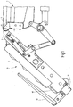
- Fig. 1 the front edge portion of a designated as a whole by 1 Seat part aborted and shown without resting seat cushion.
- a Anschstelle 3 of the edge region is by means of hinge pin 5
- the upper end a support structure 7 for a pivotable leg rest 9 ( Figure 1) and an in this retractable and extendable out of her footrest assembly 11 is shown.
- Figure 1 located on front (lower) end of the footrest assembly 11 in per se known Way a hinged tread element 13, which in Fig. 1 in folded Position is shown.
- Fig. 1 is a cushion support of the leg rest 9, without the pad cover is shown, designated 15.
- Fig. 1 shows the end of a Padding support 17 of the footrest assembly 11.
- Figs. 2 and 3 are neither the cushion support 15 of the leg rest 9 nor the cushion support 17 of the Footrest assembly 11 plotted so that the look inside Structures 7 and 21 of leg rest 9 andRIC spanan Aunt 11 released are, which are both formed in a kind of flat box, wherein the Footrest assembly 11 telescopically fitting in the support structure 7 of Leg rest 9 is retractable, the side walls 19 each have a sliding guide for the structure 21 of the leg rest 11 form.
- FIGS. 2 and 3 the structure 7 of FIG Leg rest 9 a pivot bearing 23 and on the structure 21 of the footrest assembly 11 a pivot bearing 25.
- the end of a rack 27 is hinged, while on the pivot bearing 25 of the footrest assembly 11 a similar rack 29 hinged stores.
- the storage of the racks 27 and 29 takes place here so that they are movable in a common pivoting plane parallel to the Main plane of the bottom parts 31 and 33 of the structure 7 of the leg rest 9 or the structure 21 of the footrest assembly 11 extends.
- the racks 27 and 29 are in the housing 35 of an electric gear motor 37 so led that its output side pinion (in Figs. 2 and 3 only symbolized by a circle 39), between the racks 27 and 29 is in mesh with the latter two.
- Fig. 2 shows the footrest assembly 11 in her in the leg rest 9 completely retracted position.
- the articulation points are the Racks 27, 29 on the pivot bearings 23 and 25 relative to the Main longitudinal axis of leg rest 9 and footrest assembly 11 offset so that the racks 27 and 29 are approximately diagonal to the extended by the bottom portion 33 of the structure 21 defined rectangular area, allowing for the accommodation of the racks 27, 29 available standing installation space is used optimally, so that due to the corresponding length of the racks 27, 29 a desired long displacement is available.
- Fig. 3 shows the footrest assembly 11 in about 3/4 of its way extended position. As can be seen, stands for the length of the displacement approximately the combined length of both racks 27, 29th available so that sufficiently long extension length despite the in the retracted state given compactness is available. Like also can be seen in the comparison of Figs. 2 and 3, the position of the unit geared motor 37 and gearbox 35 relative to the structures 7 and 21 mobile. This is due to the fact that the unit geared motor 37 and gear housing 35 on the racks 27th and 29 is cantilevered.
Landscapes
- Engineering & Computer Science (AREA)
- Aviation & Aerospace Engineering (AREA)
- Passenger Equipment (AREA)
- Seats For Vehicles (AREA)
- Chair Legs, Seat Parts, And Backrests (AREA)
- Push-Button Switches (AREA)
Abstract
Description
- Fig. 1 eine teils abgebrochen und schematisiert gezeichnete Seitenansicht nur des vorderen Randbereiches des Sitzteiles des Ausführungsbeispieles des erfindungsgemäßen Fluggastsitzes, ohne eingezeichnetes Sitzpolster, wobei sich die Beinauflage mit in sie eingefahrener Fußstützenanordnung in aus der Nicht-Gebrauchsstellung lediglich leicht angehobener Stellung befindet;
- Fig. 2 eine gegenüber Fig. 1 in kleinerem Maßstab gezeichnete Draufsicht der Beinauflage mit in sie eingefahrener Fußstützenanordnung, wobei Polsterträger von Beinauflage und Fußstützenanordnung weggelassen sind und somit der Einblick in die kastenartigen Strukturen von Beinauflage und Fußstützenanordnung freigegeben ist, und
- Fig. 3 eine der Fig. 2 entsprechende Draufsicht, wobei jedoch die Fußstützenanordnung in voll ausgefahrener Stellung gezeigt ist.
Claims (8)
- Fluggastsitz mit Sitzkomponenten wie Rückenlehne, Sitzteil (1) und an dessen vorderem Randbereich (3) angelenkter Beinauflage (9), die zwischen einer abgesenkten Nicht-Gebrauchsstellung und angehobenen Gebrauchsstellungen schwenkbar ist, und mit einer Fußstützenanordnung (11), die an der Beinauflage (9) längs verschiebbar geführt, zwischen einer eingefahrenen Stellung und eine Verlängerung der Beinauflage (9) bildenden, ausgefahrenen Stellungen bewegbar und mit einem Antrieb (35, 37) verbunden ist, der zwischen einem unwirksamen Ruhezustand und einem eine Verschiebekraft an der Fußstützenanordnung (11) erzeugenden Wirkzustand umschaltbar ist, dadurch gekennzeichnet, dass ein umsteuerbarer, in zwei Wirkzustände schaltbarer Antrieb (35, 37) zum wahlweisen Erzeugen einer das Einfahren oder das Ausfahren der Fußstützenanordnung (11) erzeugenden Verschiebekraft vorgesehen ist.
- Fluggastsitz nach Anspruch 1, dadurch gekennzeichnet, dass der Antrieb einen die Drehrichtungsumkehr ermöglichenden elektrischen Getriebemotor (35, 37) aufweist.
- Fluggastsitz nach Anspruch 2, dadurch gekennzeichnet, dass der Getriebemotor (35, 37) ein abtriebsseitiges Zahnritzel (39) aufweist, das mit zwei zueinander parallel geführten Zahnstangen (27, 29) in Eingriff ist, deren eine endseitig mit der Struktur (7) der Beinauflage (9 und deren andere endseits mit der zu dieser bewegbaren Fußstützenanordnung (11) jeweils gelenkig verbunden ist.
- Fluggastsitz nach Anspruch 3, dadurch gekennzeichnet, dass die Zahnstangen (27, 29) am Gehäuse (35) des Getriebemotors (35, 37) verschiebbar geführt sind.
- Fluggastsitz nach Anspruch 4, dadurch gekennzeichnet, dass der Getriebemotor (35, 37) mit seinem Gehäuse (35) auf den in ihm geführten Zahnstangen (27, 29) fliegend gelagert ist.
- Fluggastsitz nach Anspruch 5, dadurch gekennzeichnet, dass die Struktur (7) der Beinauflage (9) in der Art eines oben offenen, flachen Kastens ausgebildet ist, dessen obere Seite durch einen Polsterträger (15) der Beinauflage (9) bedeckt ist und an dessen sich vom Polsterträger (15) zum Bodenteil (31) der Kastenstruktur (7) erstreckenden Seitenwänden (19) eine Verschiebeführung für die zwischen Polsterträger (15) und Bodenteil (31) in die kastenartige Struktur (7) einfahrbare Fußstützenanordnung (11) angeordnet ist.
- Fluggastsitz nach Anspruch 6, dadurch gekennzeichnet, dass die Fußstützenanordnung (11) in der Art eines hohlkastenartigen Schlittens mit einem Bodenteil (33) ausgebildet ist, der sich in der in die Struktur (7) der Beinauflage (9) eingefahrenen Stellung eng benachbart zum Bodenteil (31) der Kastenstruktur der Beinauflage (9) erstreckt, so dass zwischen Bodenteil (33) der Fußstützenanordnung (11) und Polsterträger (15) der Beinauflage (9) Raum für den darin befindlichen Getriebemotor (35, 37) verbleibt.
- Fluggastsitz nach Anspruch 7, dadurch gekennzeichnet, dass die Enden der Zahnstangen (27, 29) an der Struktur (7) der Beinauflage (9) und an der Struktur (21) des Schlittens der Fußstützenanordnung (11) relativ zu deren Hauptlängsachse an in Querrichtung so versetzten Anlenkstellen (23, 25) angebracht sind, dass sich die Zahnstangen (27, 29) bei der eingefahrenen Stellung der Fußstützenanordnung (11) näherungsweise diagonal zur Rechteckfläche der Bodenteile (31, 33)erstrecken.
Applications Claiming Priority (2)
| Application Number | Priority Date | Filing Date | Title |
|---|---|---|---|
| DE102004008267A DE102004008267A1 (de) | 2004-02-20 | 2004-02-20 | Fluggastsitz |
| DE102004008267 | 2004-02-20 |
Publications (2)
| Publication Number | Publication Date |
|---|---|
| EP1574428A1 true EP1574428A1 (de) | 2005-09-14 |
| EP1574428B1 EP1574428B1 (de) | 2007-05-16 |
Family
ID=34813520
Family Applications (1)
| Application Number | Title | Priority Date | Filing Date |
|---|---|---|---|
| EP05000968A Expired - Lifetime EP1574428B1 (de) | 2004-02-20 | 2005-01-19 | Fluggastsitz |
Country Status (4)
| Country | Link |
|---|---|
| US (1) | US7201451B2 (de) |
| EP (1) | EP1574428B1 (de) |
| AT (1) | ATE362446T1 (de) |
| DE (2) | DE102004008267A1 (de) |
Cited By (1)
| Publication number | Priority date | Publication date | Assignee | Title |
|---|---|---|---|---|
| FR2958890A1 (fr) * | 2010-04-20 | 2011-10-21 | Faurecia Sieges Automobile | Dispositif de reglage de la longueur d'assise pour un siege d'automobile, et siege comportant un tel dispositif |
Families Citing this family (16)
| Publication number | Priority date | Publication date | Assignee | Title |
|---|---|---|---|---|
| US20070024101A1 (en) * | 2005-08-01 | 2007-02-01 | Kuang Yu Metal Working Co., Ltd. | Footrest assembly for a massage chair |
| DE102005047657A1 (de) * | 2005-10-05 | 2007-04-12 | Recaro Aircraft Seating Gmbh & Co. Kg | Sitzvorrichtung, insbesondere Flugzeug- oder Fahrzeugsitzvorrichtung |
| JP4635835B2 (ja) * | 2005-11-10 | 2011-02-23 | アイシン精機株式会社 | 車両用シートの電動伸縮装置 |
| WO2010114814A1 (en) * | 2009-03-30 | 2010-10-07 | Weber Aircraft Llc | Leg-rests for passenger seats |
| US8444225B2 (en) * | 2010-02-02 | 2013-05-21 | Be Aerospace, Inc. | Deployable legrest |
| CN201895591U (zh) * | 2010-10-18 | 2011-07-13 | 李宛豫 | 改进的座椅结构 |
| CN202234113U (zh) * | 2011-08-17 | 2012-05-30 | 李宛豫 | 翻转式脚托 |
| CN202243079U (zh) * | 2011-08-17 | 2012-05-30 | 李宛豫 | 翻转式脚托 |
| CN103419691B (zh) * | 2012-05-25 | 2015-10-14 | 李宛豫 | 翻转式脚托 |
| US9301895B2 (en) | 2013-03-15 | 2016-04-05 | Stryker Corporation | Medical support apparatus |
| US10059455B2 (en) | 2016-10-26 | 2018-08-28 | Ami Industries, Inc. | Cabin attendant seat legrest with an extendable footrest |
| US11001383B2 (en) | 2016-12-02 | 2021-05-11 | Ami Industries, Inc. | Suspension recline system |
| US10525861B2 (en) * | 2017-03-22 | 2020-01-07 | Ford Global Technologies, Llc | Leg support options for sleeper seats |
| GB2560996B (en) | 2017-03-31 | 2021-04-14 | Ipeco Holdings Ltd | Seating apparatus |
| US10513212B1 (en) * | 2018-06-28 | 2019-12-24 | Faurecia Automotive Seating, Llc | Leg support for vehicle seat |
| DE102021211434A1 (de) | 2021-10-11 | 2023-04-13 | Adient Us Llc | Wadenstützanordnung und Sitz |
Citations (4)
| Publication number | Priority date | Publication date | Assignee | Title |
|---|---|---|---|---|
| US5352020A (en) * | 1992-07-10 | 1994-10-04 | Weber Aircraft, Inc. | Hydraulic extendable legrest |
| US6081976A (en) * | 1999-11-03 | 2000-07-04 | Sunshine Kids Juvenile Products, Llc | Belt shortening device |
| US20020063449A1 (en) * | 2000-01-14 | 2002-05-30 | Plant Tommy G. | Passenger seat with fabric suspension legrest |
| US20020109389A1 (en) * | 2001-02-15 | 2002-08-15 | Minebea Co., Ltd. | Footrest unit for passenger seat |
Family Cites Families (13)
| Publication number | Priority date | Publication date | Assignee | Title |
|---|---|---|---|---|
| US1679426A (en) * | 1925-06-11 | 1928-08-07 | Howe Folding Furniture Inc | Folding table |
| US1902795A (en) * | 1930-08-30 | 1933-03-21 | Remington Rand Inc | Drawer suspension |
| US2571080A (en) * | 1945-11-27 | 1951-10-09 | Heywood Wakefield Co | Combination leg rest and reclining seat for vehicles |
| US2563629A (en) * | 1946-04-19 | 1951-08-07 | Heywood Wakefield Co | Vertically swinging adjustable leg and foot rest |
| US2602490A (en) * | 1949-04-14 | 1952-07-08 | Ajax Cons Company | Horizontally movable footrest |
| US3863980A (en) * | 1973-06-15 | 1975-02-04 | Elliot Ciner | Geriatric chair |
| US5507562A (en) * | 1994-07-28 | 1996-04-16 | Wieland Designs Inc. | Extensible foot rest |
| US5651587A (en) * | 1995-06-09 | 1997-07-29 | P.L. Porter Co. | Vehicle seat and system for controlling the same |
| US20010000639A1 (en) * | 1997-02-20 | 2001-05-03 | Singapore Airlines Ltd. | Transport accommodation |
| FR2818595B1 (fr) * | 2000-12-26 | 2003-03-07 | Eads Sogerma | Fauteuil convertible en lit, notamment pour aeronef |
| US20020101106A1 (en) * | 2001-02-01 | 2002-08-01 | Kim Stephen E. | No-back drive mechanism for use with aircraft seat actuators |
| DE10209186B4 (de) * | 2002-03-04 | 2007-10-18 | Daimlerchrysler Ag | Fahrzeugsitz mit Fußstütze |
| US6742206B1 (en) * | 2003-04-03 | 2004-06-01 | Tai-Kang Han | Nurse robot |
-
2004
- 2004-02-20 DE DE102004008267A patent/DE102004008267A1/de not_active Ceased
-
2005
- 2005-01-19 AT AT05000968T patent/ATE362446T1/de not_active IP Right Cessation
- 2005-01-19 EP EP05000968A patent/EP1574428B1/de not_active Expired - Lifetime
- 2005-01-19 DE DE502005000716T patent/DE502005000716D1/de not_active Expired - Lifetime
- 2005-02-17 US US11/059,639 patent/US7201451B2/en not_active Expired - Lifetime
Patent Citations (4)
| Publication number | Priority date | Publication date | Assignee | Title |
|---|---|---|---|---|
| US5352020A (en) * | 1992-07-10 | 1994-10-04 | Weber Aircraft, Inc. | Hydraulic extendable legrest |
| US6081976A (en) * | 1999-11-03 | 2000-07-04 | Sunshine Kids Juvenile Products, Llc | Belt shortening device |
| US20020063449A1 (en) * | 2000-01-14 | 2002-05-30 | Plant Tommy G. | Passenger seat with fabric suspension legrest |
| US20020109389A1 (en) * | 2001-02-15 | 2002-08-15 | Minebea Co., Ltd. | Footrest unit for passenger seat |
Cited By (3)
| Publication number | Priority date | Publication date | Assignee | Title |
|---|---|---|---|---|
| FR2958890A1 (fr) * | 2010-04-20 | 2011-10-21 | Faurecia Sieges Automobile | Dispositif de reglage de la longueur d'assise pour un siege d'automobile, et siege comportant un tel dispositif |
| FR2958889A1 (fr) * | 2010-04-20 | 2011-10-21 | Faurecia Sieges D Automobiles | Dispositif de reglage de la longueur d'assise pour un siege d'automobile, et siege comportant un tel dispositif |
| US8579373B2 (en) | 2010-04-20 | 2013-11-12 | Faurecia Sieges D'automobile | Device for adjusting the length of the seat base for a motor vehicle seat and seat comprising such a device |
Also Published As
| Publication number | Publication date |
|---|---|
| DE102004008267A1 (de) | 2005-09-08 |
| US20050184575A1 (en) | 2005-08-25 |
| ATE362446T1 (de) | 2007-06-15 |
| DE502005000716D1 (de) | 2007-06-28 |
| EP1574428B1 (de) | 2007-05-16 |
| US7201451B2 (en) | 2007-04-10 |
Similar Documents
| Publication | Publication Date | Title |
|---|---|---|
| EP1574428B1 (de) | Fluggastsitz | |
| DE102006035421B4 (de) | Elektrisches Teleskopgerät für einen Fahrzeugsitz | |
| DE4237855C1 (de) | Klapptisch für Kraftfahrzeuge | |
| DE102004024559B4 (de) | Tischeinheit für einen Fahrgastsitz | |
| DE69125935T2 (de) | Chaiselongue mit verstellbarer überdachung | |
| DE102006056651A1 (de) | Mittelarmlehne mit Parallelverstellungsmöglichkeiten | |
| DE69522287T2 (de) | Stapelbarer stuhl | |
| EP1989962B1 (de) | Synchronmechanik für Bürostühle | |
| DE10358478A1 (de) | Fluggastsitz | |
| EP1564139B1 (de) | Fluggastsitz | |
| DE202005000574U1 (de) | Sessel | |
| DE202012100960U1 (de) | Sitz-/Liegemöbel | |
| EP1358823A1 (de) | Variables Sitz- und Liegemöbel | |
| DE102020206224B4 (de) | Sitzeinrichtung für ein Kraftfahrzeug | |
| DE202019103170U1 (de) | Ausziehtisch | |
| DE10312041A1 (de) | Konsoleinrichtung, insbesondere für Kraftfahrzeuge | |
| DE4217535C2 (de) | Ausziehbare Bettcouch | |
| DE102010010306B4 (de) | Sitzschwenkvorrichtung | |
| DE602006000496T2 (de) | Sitz-und/oder Liegemöbel | |
| DE102004030363A1 (de) | Passagiersitz, insbesondere Fluggastsitz | |
| DE202025106526U1 (de) | Klapptisch, insbesondere für einen Fahrzeugsitz | |
| DE202010003173U1 (de) | Sitzschwenkvorrichtung | |
| DE202022106672U1 (de) | Zugsitz | |
| DE102017107367A1 (de) | Mechanismus zum Herausschieben eines Sitzes | |
| DE102024202616A1 (de) | Klapptischsystem mit einer Ver- und Entriegelungsvorrichtung und Fahrzeug mit dem Klapptischsystem |
Legal Events
| Date | Code | Title | Description |
|---|---|---|---|
| PUAI | Public reference made under article 153(3) epc to a published international application that has entered the european phase |
Free format text: ORIGINAL CODE: 0009012 |
|
| 17P | Request for examination filed |
Effective date: 20050712 |
|
| AK | Designated contracting states |
Kind code of ref document: A1 Designated state(s): AT BE BG CH CY CZ DE DK EE ES FI FR GB GR HU IE IS IT LI LT LU MC NL PL PT RO SE SI SK TR |
|
| AX | Request for extension of the european patent |
Extension state: AL BA HR LV MK YU |
|
| AKX | Designation fees paid |
Designated state(s): AT BE BG CH CY CZ DE DK EE ES FI FR GB GR HU IE IS IT LI LT LU MC NL PL PT RO SE SI SK TR |
|
| GRAP | Despatch of communication of intention to grant a patent |
Free format text: ORIGINAL CODE: EPIDOSNIGR1 |
|
| RAP1 | Party data changed (applicant data changed or rights of an application transferred) |
Owner name: RECARO AIRCRAFT SEATING GMBH & CO. KG |
|
| GRAS | Grant fee paid |
Free format text: ORIGINAL CODE: EPIDOSNIGR3 |
|
| GRAA | (expected) grant |
Free format text: ORIGINAL CODE: 0009210 |
|
| AK | Designated contracting states |
Kind code of ref document: B1 Designated state(s): AT BE BG CH CY CZ DE DK EE ES FI FR GB GR HU IE IS IT LI LT LU MC NL PL PT RO SE SI SK TR |
|
| PG25 | Lapsed in a contracting state [announced via postgrant information from national office to epo] |
Ref country code: FI Free format text: LAPSE BECAUSE OF FAILURE TO SUBMIT A TRANSLATION OF THE DESCRIPTION OR TO PAY THE FEE WITHIN THE PRESCRIBED TIME-LIMIT Effective date: 20070516 |
|
| REG | Reference to a national code |
Ref country code: GB Ref legal event code: FG4D Free format text: NOT ENGLISH |
|
| GBT | Gb: translation of ep patent filed (gb section 77(6)(a)/1977) |
Effective date: 20070515 |
|
| REG | Reference to a national code |
Ref country code: CH Ref legal event code: EP |
|
| GBT | Gb: translation of ep patent filed (gb section 77(6)(a)/1977) |
Effective date: 20070531 |
|
| REG | Reference to a national code |
Ref country code: IE Ref legal event code: FG4D Free format text: LANGUAGE OF EP DOCUMENT: GERMAN |
|
| REF | Corresponds to: |
Ref document number: 502005000716 Country of ref document: DE Date of ref document: 20070628 Kind code of ref document: P |
|
| PG25 | Lapsed in a contracting state [announced via postgrant information from national office to epo] |
Ref country code: SE Free format text: LAPSE BECAUSE OF FAILURE TO SUBMIT A TRANSLATION OF THE DESCRIPTION OR TO PAY THE FEE WITHIN THE PRESCRIBED TIME-LIMIT Effective date: 20070816 |
|
| PG25 | Lapsed in a contracting state [announced via postgrant information from national office to epo] |
Ref country code: ES Free format text: LAPSE BECAUSE OF FAILURE TO SUBMIT A TRANSLATION OF THE DESCRIPTION OR TO PAY THE FEE WITHIN THE PRESCRIBED TIME-LIMIT Effective date: 20070827 |
|
| PG25 | Lapsed in a contracting state [announced via postgrant information from national office to epo] |
Ref country code: IS Free format text: LAPSE BECAUSE OF FAILURE TO SUBMIT A TRANSLATION OF THE DESCRIPTION OR TO PAY THE FEE WITHIN THE PRESCRIBED TIME-LIMIT Effective date: 20070916 |
|
| ET | Fr: translation filed | ||
| NLV1 | Nl: lapsed or annulled due to failure to fulfill the requirements of art. 29p and 29m of the patents act | ||
| PG25 | Lapsed in a contracting state [announced via postgrant information from national office to epo] |
Ref country code: PL Free format text: LAPSE BECAUSE OF FAILURE TO SUBMIT A TRANSLATION OF THE DESCRIPTION OR TO PAY THE FEE WITHIN THE PRESCRIBED TIME-LIMIT Effective date: 20070516 |
|
| REG | Reference to a national code |
Ref country code: IE Ref legal event code: FD4D |
|
| PG25 | Lapsed in a contracting state [announced via postgrant information from national office to epo] |
Ref country code: DK Free format text: LAPSE BECAUSE OF FAILURE TO SUBMIT A TRANSLATION OF THE DESCRIPTION OR TO PAY THE FEE WITHIN THE PRESCRIBED TIME-LIMIT Effective date: 20070516 Ref country code: SI Free format text: LAPSE BECAUSE OF FAILURE TO SUBMIT A TRANSLATION OF THE DESCRIPTION OR TO PAY THE FEE WITHIN THE PRESCRIBED TIME-LIMIT Effective date: 20070516 Ref country code: NL Free format text: LAPSE BECAUSE OF FAILURE TO SUBMIT A TRANSLATION OF THE DESCRIPTION OR TO PAY THE FEE WITHIN THE PRESCRIBED TIME-LIMIT Effective date: 20070516 Ref country code: PT Free format text: LAPSE BECAUSE OF FAILURE TO SUBMIT A TRANSLATION OF THE DESCRIPTION OR TO PAY THE FEE WITHIN THE PRESCRIBED TIME-LIMIT Effective date: 20071016 Ref country code: CZ Free format text: LAPSE BECAUSE OF FAILURE TO SUBMIT A TRANSLATION OF THE DESCRIPTION OR TO PAY THE FEE WITHIN THE PRESCRIBED TIME-LIMIT Effective date: 20070516 Ref country code: IE Free format text: LAPSE BECAUSE OF FAILURE TO SUBMIT A TRANSLATION OF THE DESCRIPTION OR TO PAY THE FEE WITHIN THE PRESCRIBED TIME-LIMIT Effective date: 20070516 Ref country code: BG Free format text: LAPSE BECAUSE OF FAILURE TO SUBMIT A TRANSLATION OF THE DESCRIPTION OR TO PAY THE FEE WITHIN THE PRESCRIBED TIME-LIMIT Effective date: 20070816 |
|
| PG25 | Lapsed in a contracting state [announced via postgrant information from national office to epo] |
Ref country code: LT Free format text: LAPSE BECAUSE OF FAILURE TO SUBMIT A TRANSLATION OF THE DESCRIPTION OR TO PAY THE FEE WITHIN THE PRESCRIBED TIME-LIMIT Effective date: 20070516 Ref country code: SK Free format text: LAPSE BECAUSE OF FAILURE TO SUBMIT A TRANSLATION OF THE DESCRIPTION OR TO PAY THE FEE WITHIN THE PRESCRIBED TIME-LIMIT Effective date: 20070516 |
|
| PLBE | No opposition filed within time limit |
Free format text: ORIGINAL CODE: 0009261 |
|
| STAA | Information on the status of an ep patent application or granted ep patent |
Free format text: STATUS: NO OPPOSITION FILED WITHIN TIME LIMIT |
|
| 26N | No opposition filed |
Effective date: 20080219 |
|
| PG25 | Lapsed in a contracting state [announced via postgrant information from national office to epo] |
Ref country code: GR Free format text: LAPSE BECAUSE OF FAILURE TO SUBMIT A TRANSLATION OF THE DESCRIPTION OR TO PAY THE FEE WITHIN THE PRESCRIBED TIME-LIMIT Effective date: 20070817 |
|
| PG25 | Lapsed in a contracting state [announced via postgrant information from national office to epo] |
Ref country code: RO Free format text: LAPSE BECAUSE OF FAILURE TO SUBMIT A TRANSLATION OF THE DESCRIPTION OR TO PAY THE FEE WITHIN THE PRESCRIBED TIME-LIMIT Effective date: 20070516 |
|
| BERE | Be: lapsed |
Owner name: RECARO AIRCRAFT SEATING G.M.B.H. & CO. KG Effective date: 20080131 |
|
| PG25 | Lapsed in a contracting state [announced via postgrant information from national office to epo] |
Ref country code: MC Free format text: LAPSE BECAUSE OF NON-PAYMENT OF DUE FEES Effective date: 20080131 |
|
| PG25 | Lapsed in a contracting state [announced via postgrant information from national office to epo] |
Ref country code: EE Free format text: LAPSE BECAUSE OF FAILURE TO SUBMIT A TRANSLATION OF THE DESCRIPTION OR TO PAY THE FEE WITHIN THE PRESCRIBED TIME-LIMIT Effective date: 20070516 |
|
| PG25 | Lapsed in a contracting state [announced via postgrant information from national office to epo] |
Ref country code: BE Free format text: LAPSE BECAUSE OF NON-PAYMENT OF DUE FEES Effective date: 20080131 |
|
| PG25 | Lapsed in a contracting state [announced via postgrant information from national office to epo] |
Ref country code: AT Free format text: LAPSE BECAUSE OF NON-PAYMENT OF DUE FEES Effective date: 20080119 |
|
| PG25 | Lapsed in a contracting state [announced via postgrant information from national office to epo] |
Ref country code: CY Free format text: LAPSE BECAUSE OF FAILURE TO SUBMIT A TRANSLATION OF THE DESCRIPTION OR TO PAY THE FEE WITHIN THE PRESCRIBED TIME-LIMIT Effective date: 20070516 |
|
| REG | Reference to a national code |
Ref country code: CH Ref legal event code: PL |
|
| PG25 | Lapsed in a contracting state [announced via postgrant information from national office to epo] |
Ref country code: LI Free format text: LAPSE BECAUSE OF NON-PAYMENT OF DUE FEES Effective date: 20090131 Ref country code: CH Free format text: LAPSE BECAUSE OF NON-PAYMENT OF DUE FEES Effective date: 20090131 |
|
| PG25 | Lapsed in a contracting state [announced via postgrant information from national office to epo] |
Ref country code: LU Free format text: LAPSE BECAUSE OF NON-PAYMENT OF DUE FEES Effective date: 20080119 Ref country code: HU Free format text: LAPSE BECAUSE OF FAILURE TO SUBMIT A TRANSLATION OF THE DESCRIPTION OR TO PAY THE FEE WITHIN THE PRESCRIBED TIME-LIMIT Effective date: 20071117 |
|
| PG25 | Lapsed in a contracting state [announced via postgrant information from national office to epo] |
Ref country code: TR Free format text: LAPSE BECAUSE OF FAILURE TO SUBMIT A TRANSLATION OF THE DESCRIPTION OR TO PAY THE FEE WITHIN THE PRESCRIBED TIME-LIMIT Effective date: 20070516 |
|
| REG | Reference to a national code |
Ref country code: FR Ref legal event code: PLFP Year of fee payment: 12 |
|
| REG | Reference to a national code |
Ref country code: FR Ref legal event code: PLFP Year of fee payment: 13 |
|
| PGFP | Annual fee paid to national office [announced via postgrant information from national office to epo] |
Ref country code: GB Payment date: 20170125 Year of fee payment: 13 |
|
| PGFP | Annual fee paid to national office [announced via postgrant information from national office to epo] |
Ref country code: IT Payment date: 20170125 Year of fee payment: 13 |
|
| REG | Reference to a national code |
Ref country code: FR Ref legal event code: PLFP Year of fee payment: 14 |
|
| GBPC | Gb: european patent ceased through non-payment of renewal fee |
Effective date: 20180119 |
|
| PG25 | Lapsed in a contracting state [announced via postgrant information from national office to epo] |
Ref country code: GB Free format text: LAPSE BECAUSE OF NON-PAYMENT OF DUE FEES Effective date: 20180119 |
|
| PG25 | Lapsed in a contracting state [announced via postgrant information from national office to epo] |
Ref country code: IT Free format text: LAPSE BECAUSE OF NON-PAYMENT OF DUE FEES Effective date: 20180119 |
|
| PGFP | Annual fee paid to national office [announced via postgrant information from national office to epo] |
Ref country code: DE Payment date: 20220120 Year of fee payment: 18 |
|
| PGFP | Annual fee paid to national office [announced via postgrant information from national office to epo] |
Ref country code: FR Payment date: 20220124 Year of fee payment: 18 |
|
| REG | Reference to a national code |
Ref country code: DE Ref legal event code: R119 Ref document number: 502005000716 Country of ref document: DE |
|
| PG25 | Lapsed in a contracting state [announced via postgrant information from national office to epo] |
Ref country code: DE Free format text: LAPSE BECAUSE OF NON-PAYMENT OF DUE FEES Effective date: 20230801 |
|
| PG25 | Lapsed in a contracting state [announced via postgrant information from national office to epo] |
Ref country code: FR Free format text: LAPSE BECAUSE OF NON-PAYMENT OF DUE FEES Effective date: 20230131 |