EP1570386B1 - Verfahren und vorrichtung zur vorhersage von biegelebensdauern elektrischer leitungen und/oder drahtschutzgliedern, die durch vibrationen verursacht werden, und aufzeichnungsmedium-speicherprogramm - Google Patents
Verfahren und vorrichtung zur vorhersage von biegelebensdauern elektrischer leitungen und/oder drahtschutzgliedern, die durch vibrationen verursacht werden, und aufzeichnungsmedium-speicherprogramm Download PDFInfo
- Publication number
- EP1570386B1 EP1570386B1 EP03774211A EP03774211A EP1570386B1 EP 1570386 B1 EP1570386 B1 EP 1570386B1 EP 03774211 A EP03774211 A EP 03774211A EP 03774211 A EP03774211 A EP 03774211A EP 1570386 B1 EP1570386 B1 EP 1570386B1
- Authority
- EP
- European Patent Office
- Prior art keywords
- wires
- predicting
- bending life
- finite element
- unit
- Prior art date
- Legal status (The legal status is an assumption and is not a legal conclusion. Google has not performed a legal analysis and makes no representation as to the accuracy of the status listed.)
- Expired - Lifetime
Links
Images

Classifications
-
- G—PHYSICS
- G01—MEASURING; TESTING
- G01N—INVESTIGATING OR ANALYSING MATERIALS BY DETERMINING THEIR CHEMICAL OR PHYSICAL PROPERTIES
- G01N3/00—Investigating strength properties of solid materials by application of mechanical stress
- G01N3/32—Investigating strength properties of solid materials by application of mechanical stress by applying repeated or pulsating forces
-
- G—PHYSICS
- G06—COMPUTING OR CALCULATING; COUNTING
- G06F—ELECTRIC DIGITAL DATA PROCESSING
- G06F30/00—Computer-aided design [CAD]
- G06F30/20—Design optimisation, verification or simulation
- G06F30/23—Design optimisation, verification or simulation using finite element methods [FEM] or finite difference methods [FDM]
-
- G—PHYSICS
- G01—MEASURING; TESTING
- G01N—INVESTIGATING OR ANALYSING MATERIALS BY DETERMINING THEIR CHEMICAL OR PHYSICAL PROPERTIES
- G01N2203/00—Investigating strength properties of solid materials by application of mechanical stress
- G01N2203/0014—Type of force applied
- G01N2203/0023—Bending
-
- G—PHYSICS
- G01—MEASURING; TESTING
- G01N—INVESTIGATING OR ANALYSING MATERIALS BY DETERMINING THEIR CHEMICAL OR PHYSICAL PROPERTIES
- G01N2203/00—Investigating strength properties of solid materials by application of mechanical stress
- G01N2203/02—Details not specific for a particular testing method
- G01N2203/0202—Control of the test
- G01N2203/0212—Theories, calculations
- G01N2203/0218—Calculations based on experimental data
-
- G—PHYSICS
- G06—COMPUTING OR CALCULATING; COUNTING
- G06F—ELECTRIC DIGITAL DATA PROCESSING
- G06F2111/00—Details relating to CAD techniques
- G06F2111/08—Probabilistic or stochastic CAD
-
- G—PHYSICS
- G06—COMPUTING OR CALCULATING; COUNTING
- G06F—ELECTRIC DIGITAL DATA PROCESSING
- G06F2113/00—Details relating to the application field
- G06F2113/16—Cables, cable trees or wire harnesses
Definitions
- the present invention relates to a method and apparatus for predicting bending life spans of a plurality of electric wires clamped at least two points to a predetermined part and/or their wire protecting members, the bending induced by vibrations, and a program for predicting the same.
- a plurality of electric devices are electrically connected to one another by a plurality of electric wires (referred to frequently and simply as wires) .
- the wires are bundled, by an insulation locking band, tape or the like, into a single bundle as so-called wire harness which is extendedly arranged at predetermined locations of the automobile or the like.
- the wires are protected by a wire protecting member such as a grommet are arranged at a predetermined part.
- the wires are arranged at a predetermined part of the vehicle or the like, while not bundled into one line and/or not protected by the wire protecting members.
- the vehicle is always placed in such an environment that it is always vibrated due to engine drive and the like.
- the electric wires distributed inside the engine room directly receiving the engine vibrations are repeatedly bent and deformed, and finally disconnect due to the vibrations.
- Experimental results of such are reported. In this respect, it is of particular importance to accurately predict the bending life spans of the electric wires and the wire protectingmembers.
- the prediction of the bending life spans of the electric wires and the wire protecting members is carried out by repeating design, trial manufacturing, and endurance test.
- wires distributed along an envisioned wiring path are placed on a vibration base plate.
- the vibration base plate is vibrated at a predetermined frequency and a predetermined amplitude by the vibrator, and a bending life span of the wire when it is vibrated at a specific number of vibrations is predicted.
- a development period of the vehicle tends to be shorter, and further there is a demand of enhancing a bending life prediction accuracy.
- the related bending life span predicting method in which the endurance test is repeated cannot satisfactorily reduce the development period, and cannot sufficiently meet the demand of enhancing the prediction accuracy.
- a computer aided method for predicting a life span of a wire bundle enclosed by a protective harness is described in EP 1 236 989 A2 .
- the wire bundle electrically connects a door to a vehicle's body, and accordingly the wires and the harness are exposed to a repeated bending due to opening and dosing the vehicle's door.
- the life span in view of such a bending is determined in a numerical simulation.
- the simulation comprises a modeling step for creating a finite element model of the wires and the harness, and subsequent steps for calculating the change of strain in the modeled elements and for predicting the life span based thereon.
- an object of the present invention is to provide a method and apparatus for predicting bending life spans of electric wires, which can meet the demands of a highly accurate prediction of the bending life span and of reducing the development period in an environment where vibrations occur, and a recording medium storing a program for predicting the same in such ways.
- the invention is characterized by having the following arrangement.
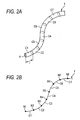
- Fig. 2A is a diagram showing an electric wire in a state it is discretized, handled in the invention.
- Fig. 2B is a diagram showing beam elements and nodes of the discrete electric wire shown in Fig. 2A.
- this electricwire 1 is discretized. Specifically, as shown in Fig. 2A, the electric wire 1 is divided (discretized) into plural beam elements C1, C2, C3, .... In other words, the electric wire 1 is regarded as an aggregation of a finite number of beam elements serially connected to one another.
- the electric wire 1 may be considered as an aggregation of beam elements C1, C2, C3, ... which are serially connected at nodes N1, N2, N3, ... to one another, as shown in Fig. 2B.
- Properties necessary for the beam element are, for example, length "1" (see Fig. 2A), a cross section area A (see Fig. 2A), a moment of inertia of area, a polar moment of inertia of area, density, amodulus of longitudinal elasticity, amodulus of transverse elasticity, and the like. Those properties may be obtained in advance by measurement or calculation. It is preferable that the properties are formed as a database, and available ad libitum.
- the length and the cross sectional area are set as geometric properties, and the moment of inertia of area, the polar moment of inertia of area, the modulus of longitudinal elasticity, and the modulus of transverse elasticity are set as material properties.
- ⁇ x ⁇ is a nodal displacement vector (or a displacement vector, simply), and an array of displacement components of all the nodes.
- the component of the nodal displacement vector ⁇ x ⁇ includes a preset vector, such as a point of constraint, and an unknown quantity.
- ⁇ F ⁇ is a net external force vector, and an array of external force components at all the nodes.
- a finite element model of the discrete wire having divided into an optional number of beam elements is formed.
- a technique which is similar to a technique disclosed in Japanese patent application No, 2002-279503, filed on September 25, 2002 by the Applicant of the present patent application, can be applied to the formation of the finite element model.
- the general matrix finite element method is described in, for example, the non-patent documents described above.
- the expression (4) holds.
- the displacement vector ⁇ x ⁇ is a relative displacement.
- a stress obtained from the displacement vector ⁇ x ⁇ is also a relative value.
- An absolute value obtained from the expression (4) is only the natural frequency ⁇ . To calculate actual displacements and stresses, it is necessary to input a load condition of an actual vibration.
- a force applied to points of constraint on a wire harness or a wire protecting member as an object under prediction of the bending life is set at an optional value, the force attending envisioned vibrations of the engine, vehicle body, and the like.
- the expression is returned from the frequency domain to the time domain by inverse Fourier transformation, whereby an amount of calculation is reduced.
- a vibration analysis of a plurality of electric wires including, for example, grommets as wire protecting members is also carried out.
- the wire protecting member is divided into a plurality of triangular finite elements, and stresses at those finite elements are obtained.
- a vibration analysis of the wire protecting member which follows the formation of the finite element model consisting of such finite elements, is carried out in a manner as in the case of the electric wire.
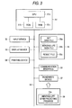
- FIG. 3 is a block diagram showing a hardware configuration constructed according to the invention.
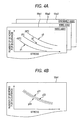
- Figs. 4A and 4B are diagrams showing bending life span data stored in a storing device in Fig. 3.
- a personal computer which has a basic configuration made up of a micro-computer 51, an input device 52, a display device 53, a printing device 54, a storing device 55, a communication interface 56, and a read/write device 57.
- the micro-computer 51 includes a CPU (central processing unit) 51a, a ROM 51b for storing a boot program and others, and a RAM 51c for temporarily storing various processing results.
- the input device 52 is a keyboard, a computer mouse and the like; the display device 53 is an LCD, a CRT and the like for displaying processing results; and the printing device 54 is a printer for printing processing results.
- the storing device 55 is, for example, a hard disc drive
- the communication interface 56 is, for example, a modem board for communicating with external devices by way of an internet, a LAN line and the like.
- the read/write device 57 reads a bending life span predicting program 59a constructed according to the invention, which is stored in a recording medium 59, and writes a result file 55c into the recording medium 59.
- Those constituent components are interconnected through an internal bus 58.
- At least a set data file 55a, a bending life data file 55b, and a result file 55c are stored in the storing device 55.
- the set data file 55a contains data preset for predicting the bending life span.
- the data represents types of electric wires and wire protecting members, atmosphere temperatures, pre-vibration shapes, constraint conditions and others, which are set in a step S1 to be described later.
- the set data file 55a contains position information of obstacles 2, such as pre-estimated stays and electric parts (see Fig. 7).
- the bending life data file 55b is an aggregation of predicting functions y1, y2 and y3 as statistically calculated using data of stresses and the number of bendings for endurance on electric wires 55a1 and 55a2, and wire protecting member (e.g., grommet) 55a3, which are gathered at different atmosphere temperatures of, for example, - 40°C, 0°C and 25 °C.
- a curve y22 represents an upper confidence interval and the curve y23 represents a lower confidence interval to a population regression function y21 obtained by the known regression analysis, as shown in Fig. 4B.
- the curve y23 of those curves y22 and y23 is used.
- the confidence interval is, for example, 95%.
- Such predicting functions are obtained under condition that the electric wire and the grommet are placed at different atmosphere temperatures. Accordingly, thebendinglife spanispredictedundermore severe statistical conditions. As a matter of course, a given statistical reliability on the predicting function is taken into account, and a computing process of the predicting function is easy. As a result, the bending life span is severelypredicted without addition of complicated processing procedures. This contributes to further enhancement of quality and wiring path plan.
- the number of bendings for endurance may be obtained using the population aggression function.
- the result file 55c contains all the stresses of the discrete wire and the discrete grommet in the finite elements, which are recorded by each natural frequency.
- the result file 55c is stored in a text format, and may be output ad libitum.
- the storing device 55 corresponds to predicting function storing means set forth in claims.
- the micro-computer 51 installs a bending life span predicting program 59a that is read by the read/write device 57 into the storing device 55. After power on, the micro-computer 51 is activated according to a boot program that is stored in the ROM 51b, and starts the bending life span predicting program 59a. According to the bending life span predicting program 59a, themicro-computer 51 predicts a bending life span of the electric wire and/or the wire protecting member induced by vibrations, causes the display device 53 and the printing device 54 to display and print the prediction result, and stores the result in the storing device 55.
- the bending life span predicting program 59a may be installed to another personal computer having the same configuration, and after installing, operates the computer as a bending life predicting device.
- the bending life span predicting program 59a may be provided through a communication line, such as an Internet, a LAN or the like, instead of the recording medium 59.
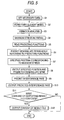
- Fig. 5 is a flow chart showing a main processing procedure according to an embodiment of the invention.
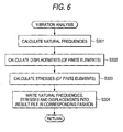
- Fig. 6 is a flow chart showing a vibration analysis processing procedure shown in Fig. 5.
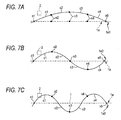
- Figs. 7A, 7B and 7C are diagrams showing predictive shapes of the electric wire in primary, secondary and tertiary vibration modes, respectively.
- data necessary for the prediction is set in a step S1.
- items to be set are at least a plurality of electric wires (exactly types of electric wires) whose bending life spans are to be predicted, wire protecting members, (sometimes not required), atmosphere temperatures, pre-vibration shapes for each wires, and constraint conditions for each electric wires.
- an input screen (not shown) is presented on the display device 53, and necessary items are entered to the input screen by use of the input device 52.
- the types of the electric wires are the types of the electric wires whose bending life spans are to be predicted.
- geometrical properties and material properties are linked to the types of the electric wires.
- the geometric properties include information about lengths and cross sections for each wire.
- the material properties are a moment of inertia of area, a polar moment of inertia of area, density a modulus of longitudinal elasticity, and a modulus of transverse elasticity. Those materials may be obtained in advance by tests, for example. Those properties concerns the finite elements in the stiffness matrix [K] of the expression (1).
- the atmosphere temperatures are temperatures around the electric wires and/or wire protecting members when the bending life span prediction is carried out, and typically -40°C, 0°C and 25°C.
- the pre-vibration shape is a shape of the electric wire or the like in a static state as indicated by reference numeral 1a in Fig. 7A. In the illustration, it is simplified and depicted linearly.
- the pre-vibration shape 1a may be manually entered by use of the input device 52, or a pre-vibration shape that was previously formed before the bending life span prediction may be used for the same.
- a pre-vibration shape as to satisfy given constraint conditions and the minimum bending radius of the electric wire is calculated in advance, and it is used for the pre-vibration shape 1a.
- the nodes n1 to n5 are connection points of the finite elements into which the electric wire is divided. Some of the nodes correspond in position to parts at which constraint members, such as connectors and clips, respectively. In this instance, the nodes n1 and n5 are put under the perfect or rotation constraint condition by the constraint members, while the remaining nodes n2 to n4 are put under the perfect free condition.
- the values set here concern the values of the finite elements in the displacement vector ⁇ x ⁇ in the expression (1).
- the plural electric wires which form a wire harness are bundled, by an insulation locking band, tape or the like, into a single bundle, and in other cases, those electric wires are not bundled.
- the wire bundling is set as the constraint condition. In setting the constraint condition of the wire bundling, it is preferable to handle the electric wires that come in contact with the insulation locking band or tape in distinction from those located on the inner side of the former electric wires. By so doing, the bending life spans of the wires can be more exactly predicted since the electric wires bundled and the electric wires not bundled are separately processed.
- those electric wires are passed through a wire protecting member, such as a grommet, and in other cases, the electric wires are arranged or distributed without using the wire protecting member.
- the plural electric wires passed through the wire protecting member are used such that as described above, in some instances, those wires are bundled together into a single bundle, and in other instances, those wires are not bundled.
- a constraint condition suitable for the wire protecting member is to be set.
- a step S2 finite element models of the electric wires and/or wire protecting members are formed.
- the finite element model of the wire protectingmember is formed by dividing the wire protecting member into plural rectangular finite elements.
- the finite element model of the electric wire is formed such that the electric wire is divided into plural beam elements.
- the step S2 corresponds to a finite element model forming step and a finite element model forming means in claims.
- a vibration analyzing process is carried out for each finite element.
- the expression (4) applies to the wire harness to calculate a natural frequency of the wire harness.
- the geometric properties and the material properties as the individual elements of the stiffness matrix [K] are calculated on the assumption that those properties are the results of composing the geometric properties and the material properties of each electric wire and/or wire protecting member.
- the natural frequency its values corresponding to, for example, the first, second and tertiary vibration modes are calculated as shown in Figs. 7A to 7C.
- the number of vibration modes to be calculated and the natural frequencies are not limited to the illustrated ones.
- the first, second and tertiary vibration modes are set as default values, and may be changed by use of the input device 52.
- steps S302 and S303 are executed in which the natural frequencies are applied to an expression obtained by Fourier transforming the expression (2) as described above to thereby calculate displacements and stresses of all the finite elements for each electric wire and/or wire protecting member.
- information as to whether or not the electric wires are bundled into one bundle and information as to whether or not specific electric wire or wires come in contact with the insulation locking band or the tape, which are set as the constraint conditions in the step S1 are incorporated regarding as the information concern all of the inertial matrix [M], the damping coefficient matrix [C], and the external force ⁇ F (t) ⁇ in the expression (2).
- a step S304 the displacements and the stresses calculated every each natural frequency are linked with (finite elements) information of the position of each electric wire and/or wire protecting member as an obj ect under prediction of the bending life, and are written into the result file.
- steps S3, S301 to S303 correspond to a vibration analyzing step and vibration analyzing unit in claims.
- a maximum stress is retrieved from those stresses recorded in the result file, for each electric wire and/or wire protecting member under prediction of the bending life.
- a predicting function to the electric wire and/or wire protecting member under prediction of the bending life is read out. Specifically, a predicting function of the atmosphere temperature as set in the step S1 to the electric wire and/or wire protecting member under prediction of the bending life is read out from the bending life data file 55b stored in the storing device 55.
- the step S4 corresponds to a maximum stress retrieving step and a maximum stress retrieving unit in claims
- the step S5 corresponds to a predicting function readout step and predicting function readout unit in claims.
- each bending life span corresponding to maximum stress of each electric wire and/or each wire protectingmember, which is obtained in the step S4, is acquired, while referring to the predicting functions read out in the step S5. From those bending life spans, a shortest bending life span is obtained.
- the shortest bending life span may be, for example, the number of bendings for endurance obtained from the bending life function in Fig. 4, or may be an endurance time calculated based on the number of bendings for endurance and the natural frequency corresponding to the former.
- the step S6 corresponds to a bending life predicting step and a bending life predicting unit in claims.
- a position corresponding to the shortest bending life span is specified from its finite element. This position specifying is useful in locating a part of the wire at which the wire is possibly disconnected.
- the position specified in the step S7 and the bending life span predicted in the step S6 are output to the display device 53. Because the position on the wire protecting member and/or the electric wire corresponding to the shortest bending life span is output in addition to the bending life span, more accurate bending life prediction is ensured.
- the step S7 corresponds to a position specifying step and position specifying means in claims, and the step S8 corresponds an output step and an output unit in claims.
- a predicted inference part is output.
- the stresses calculated for each natural frequency are stored in the result file in a state that those stresses are linked with information of the positions (finite elements) of the electric wires and/or wire protecting members. Therefore, predictive shapes canbe generated for each vibration mode from the result file, as indicated by 1a1 in Fig. 7A, 1a2 in Fig. 7B, and 1a3 in Fig. 7C.
- the position information of the obstacle 2, as described above, is stored in the storing device 55.
- the step S9 corresponds to an interference part predicting step in claims.
- a step S11 If in a step S11, it is judged that a command of outputting the result file is present, the contents of the result file 55c is output in the text format in a step S12.
- the output contents may be displayed by the display device 53 or printed on a sheet by the printing device 54. Further, the contents to be output may be designated by the input device 52. If the contents outputting is not needed, the sequence of processing steps may be ended (N in step S11).
- the embodiment of the invention succeeds in providing a method and apparatus for predicting bending life spans of electric wires or the like, which can more accurately predict bending life spans of the wires and can satisfactorily meet the demand of enhancing the prediction accuracy in an environment where vibrations occur, and a program for predicting the same in such ways.
- a disconnection life of the electric wire which is due to engine vibration of the automobile, can be predicted for a short time and without performing the endurance test. This is a very advantageous effect.
- the bending life span is predicted under severe conditions. Accordingly, the embodiment contributes to further enhancement of quality and wiring path plan.
- the invention is not limited to the embodiment above mentioned.
- the wire protecting member is not limited to the grommet.
- the invention is not limited to the inside of the automobile, but may be applied to a place in a factory where vibrations occur.
- the plural electric wires, the atmosphere temperatures, pre-vibration shapes of the plural electric wires, and constraint conditions of the plural electric wires are set, and finite element models of plural electric wires are formed. Natural frequencies for the pre-vibration shapes of the plural electric wires are calculated, and stresses in individual finite elements of the finite element models which correspond to the natural frequencies are calculated, and a maximum stress is retrieved from the calculated stresses for each electric wire. Predicting functions corresponding to the plural electric wires and the atmosphere temperatures, which are set, are read out. A bending life span corresponding to the maximum stress of each electric wire, is acquired while referring to the predicting functions read out, and a shortest bending life span is obtained from the bending life spans, and output. Accordingly, the bending life spans of the plural electric wires can be accurately predicted without performing the endurance test. As a result, there is provided a bending life predicting method which can meet the demands of reducing the development period and enhancing the prediction accuracy.
- the plural electric wires and wire protecting members, the atmosphere temperatures, pre-vibration shapes of the plural electric wires, and constraint conditions of the plural electric wires are set, and finite element models of plural electric wires are formed. Natural frequencies for the pre-vibration shapes of the plural electric wires are calculated, and stresses in individual finite elements of the finite element models which correspond to the natural frequencies are calculated, and a maximum stress is retrieved from the calculated stresses for each electric wire. Predicting functions corresponding to the plural electric wires and the atmosphere temperatures, which are set, are read out. A bending life span corresponding to the maximum stress of each electric wire, is acquired while referring to the predicting functions read out, and a shortest bending life span is obtained from the bending life spans, and output. Accordingly, the bending life spans of the plural electric wires inclusive of the wire protecting member can be accurately predicted without performing the endurance test. As a result, there is provided a bending life predicting method which can sufficiently meet the demands of reducing the development period.
- the plural electric wires are regarded as a wire-like structure of a bundle of the plural electric wires, and natural frequencies of the plural electric wires are computed. This feature results in reduction of calculation amount. Further reduction of the time taken for the bending life span prediction is realized.
- the bundling of the plural electric wires is set as one of the constraint conditions in the setting step. This ensures more exact prediction of the bending life span. Actually, in some cases, the plural electric wires are bundled into a single bundle, and in other cases, those are not bundled. The bending life span can be predicted, while those cases are clearly separated from each other.
- a position specifying step for specifying a position on the wire protecting member or the electric wire corresponding to the shortest bending life span is also specified, together with the bending life span, and is output. This feature ensures a more accurate prediction of the bending life span.
- an interference part induced by vibrations on each wire protecting member or each plural electric wires is also predicted. Accordingly, with this feature, optimum wiring paths can be designed free from wire disconnection by its contact.
- a curve representative of a lower confidence interval to a population regression function statistically calculated using data of the stresses and the number of bendings for endurance under a plurality of typical atmosphere temperatures for the wire protecting members and the electric wires is used for the predicting function. Accordingly, the bending life span is predicted under severe statistical conditions. As a matter of course, a given statistical reliability on the predicting function is taken into account, and a computing process of the predicting function is easy. As a result, the bending life span is severelypredicted without addition of complicated processing procedures. This contributes to further enhancement of quality and wiring path plan.
Landscapes
- Engineering & Computer Science (AREA)
- Physics & Mathematics (AREA)
- General Physics & Mathematics (AREA)
- Theoretical Computer Science (AREA)
- Health & Medical Sciences (AREA)
- Analytical Chemistry (AREA)
- Geometry (AREA)
- Evolutionary Computation (AREA)
- Computer Hardware Design (AREA)
- Life Sciences & Earth Sciences (AREA)
- Chemical & Material Sciences (AREA)
- General Engineering & Computer Science (AREA)
- Biochemistry (AREA)
- General Health & Medical Sciences (AREA)
- Immunology (AREA)
- Pathology (AREA)
- Investigating Strength Of Materials By Application Of Mechanical Stress (AREA)
- Testing Of Devices, Machine Parts, Or Other Structures Thereof (AREA)
Claims (9)
- Computerimplementiertes Verfahren zum Vorhersagen der Dauerbiegefestigkeit, mit dem eine Biegelebensdauer einer Vielzahl von Drähten vorhergesagt wird, die durch Schwingung induziert wird, wobei wenigstens zwei Punkte jedes der Vielzahl von Drähten eingespannt sind und das Verfahren die folgenden Schritte umfasst:einen Vorspeicherschritt (S1) des Vorspeicherns jeder Vorhersagefunktion, die Beziehungen zwischen Umgebungstemperaturen, Belastungen und Biegelebensdauern für die Vielzahl von Drähten darstellen,einen Einstellschritt (S1) des Einstellens der Vielzahl von Drähten, der Umgebungstemperaturen, von Formen der Vielzahl von Drähten vor Schwingung und Einspannbedingungen der Vielzahl von Drähten,einen Schritt (S2) des Ausbildens eines Finite-Elemente-Modells, mit dem Finite-Elemente-Modelle der Vielzahl von Drähten unter Verwendung einer Finite-Element-Methode ausgebildet werden,einen Schwingungsanalysierschritt (S3) des Berechnens von Eigenfrequenzen für die Formen vor Schwingung und des Berechnens von Belastungen in einzelnen finiten Elementen der Finite-Elemente-Modelle, die jeweils den Eigenfrequenzen entsprechen,einen Schritt (S4) des Abrufens maximaler Belastung, mit dem eine maximale Belastung von den in dem Schwingungsanalysierschritt (S3) berechneten Belastungen für jeden der Vielzahl von Drähten abgerufen wird,einen Schritt (S5) zum Auslesen von Vorhersagefunktionen, mit dem Vorhersagefunktionen gelesen werden, die jeweils den in dem Einstellschritt (S1) eingestellten Umgebungstemperaturen entsprechen,einen Schritt (S6) des Vorhersagens von Dauerbiegefestigkeit, mit dem eine Biegelebensdauer bestimmt wird, die der maximalen Belastung der Vielzahl von Drähten entspricht, wobei auf die in dem Schritt (S5) zum Auslesen von Vorhersagefunktionen ausgelesenen Vorhersagefunktionen Bezug genommen wird und eine kürzeste Biegelebensdauer aus den Biegelebensdauern ermittelt wird, undeinen Ausgabeschritt (S8) des Ausgebens der in dem Schritt (S6) zum Vorhersagen der Dauerbiegefestigkeit ermittelten kürzesten Biegelebensdauer.
- Verfahren nach Anspruch 1, wobei in dem Schwingungsanalysierschritt (S3) die Vielzahl von Drähten als eine Verdrahtungsstruktur betrachtet werden, in der die Vielzahl von Drähten gebündelt sind, und jeweils Eigenfrequenzen der Vielzahl von Drähten berechnet werden.
- Verfahren nach Anspruch 1, wobei die Vielzahl von Drähten zu einem einzelnen Bündel gebündelt sind und das Bündeln der Vielzahl von Drähten als eine der Einspannbedingungen in dem Einstellschritt (S1) eingestellt wird.
- Verfahren nach Anspruch 1, das des weiteren einen Schritt (S7) zum Spezifizieren einer Position umfasst, in dem eine Position an dem Draht spezifiziert wird, die der kürzesten Biegelebensdauer entspricht, und wobei der Ausgabeschritt (S8) die durch den Schritt (S7) zum Spezifizieren einer Position spezifizierte Position ausgibt.
- Verfahren nach Anspruch 1, wobeiin dem Schwingungsanalysierschritt (S3) Verschiebungen finiter Elemente der Finite-Elemente-Modelle berechnet werden, die den Eigenfrequenzen entsprechen,das Verfahren einen Schritt (S9) zum Vorhersagen eines Interferenzteils einschließt, in dem ein Interferenzteil an der Vielzahl von Drähten, der durch Schwingungen induziert wird, auf Basis der berechneten Verschiebungen vorhergesagt wird, undder Ausgabeschritt (S8) den vorhergesagten Interferenzteil ausgibt.
- Verfahren nach Anspruch 1, wobei eine Kurve, die einen unteren Vertrauensbereich für eine Populationsregressionsfunktion darstellt, die unter Verwendung der Belastungen und von Daten über Biegefestigkeits-Lebensdauern statistisch berechnet wird, die in einer Vielzahl typischer Umgebungstemperaturen für die Vielzahl von Drähten ermittelt werden, für die Vorhersagefunktion verwendet wird.
- Computerlesbares Aufzeichnungsmedium, das ein Programm zum Vorhersagen von Biegelebensdauern einer Vielzahl von Drähten, die durch Schwingungen induziert werden, speichert, wobei das Programm einen Computer veranlasst, alle Schritte nach Anspruch 1 auszuführen.
- Vorrichtung zum Vorhersagen von Dauerbiegefestigkeiten, mit der Biegelebensdauern einer Vielzahl von Drähten, die durch Schwingungen induziert werden, vorhergesagt werden, wobei wenigstens zwei Punkte jedes der Vielzahl von Drähten eingespannt sind und die Vorrichtung umfasst:eine Vorspeichereinheit (55) zum Vorspeichern jeder Vorhersagefunktion (55a1, 55a2, 55a3), die Beziehungen zwischen Umgebungstemperaturen, Belastungen und Biegelebensdauern für die Vielzahl von Drähten (1) darstellen,eine Einstelleinheit (52) zum Einstellen der Vielzahl von Drähten (1), der Umgebungstemperaturen, von Formen der Vielzahl von Drähten (1) vor Schwingung und Einspannbedingungen der Vielzahl von Drähten (1),eine Einheit (51) zum Ausbilden eines Finite-Elemente-Modells, die Finite-Elemente-Modelle der Vielzahl von Drähten (1) unter Verwendung einer Finite-Element-Methode ausbildet,eine Schwingungsanalysiereinheit (51) zum Berechnen von Eigenfrequenzen für die Formen vor Schwingung und zum Berechnen von Belastungen in einzelnen finiten Elementen der Finite-Elemente-Modelle, die jeweils den Eigenfrequenzen entsprechen,eine Einheit (51) zum Abrufen einer maximalen Belastung, die eine maximale Belastung aus den in der Schwingungsanalysiereinheit (51) berechneten Belastungen für jeden der Vielzahl von Drähten (1) abruft,eine Einheit (51) zum Auslesen von Vorhersagefunktionen, die die Vorhersagefunktionen (55a1, 55a2, 55a3) liest, die jeweils den in der Einstelleinheit (52) eingestellten Umgebungstemperaturen entsprechen,eine Einheit (51) zum Vorhersagen einer Dauerbiegefestigkeit, die eine Biegelebensdauer, die der maximalen Belastung jedes der Vielzahl von Drähten (1) entspricht, unter Bezugnahme auf die in der Einheit (51) zum Auslesen von Vorhersagefunktionen ausgelesenen Vorhersagefunktionen (55a1, 55a2, 55a3) bestimmt und eine kürzeste Biegelebensdauer aus den Biegelebensdauern ermittelt, undeine Ausgabeeinheit (53, 54) zum Ausgeben der in der Einheit (51) zum Vorhersagen der Dauerbiegefestigkeit ermittelten kürzesten Biegelebensdauer.
- Vorrichtung nach Anspruch 8, wobeidie Schwingungsanalysiereinheit (51) Verschiebungen finiter Elemente der Finite-Elemente-Modelle berechnet, die den Eigenfrequenzen entsprechen,die Vorrichtung eine Einheit (51) zum Vorhersagen eines Interferenzteils enthält, die einen Interferenzteil an der Vielzahl von Drähten (1), die an dem Draht-Schutzelement durch Schwingungen induziert wird, auf Basis der berechneten Verschiebungen vorhersagt, unddie Ausgabeeinheit (53, 54) den vorhergesagten Interferenzteil ausgibt.
Applications Claiming Priority (5)
| Application Number | Priority Date | Filing Date | Title |
|---|---|---|---|
| JP2002345220 | 2002-11-28 | ||
| JP2002345220 | 2002-11-28 | ||
| JP2003364516A JP4250059B2 (ja) | 2002-11-28 | 2003-10-24 | 振動をともなう電線及び/又は電線保護部材の屈曲寿命予測方法、その装置、並びにそのプログラム |
| JP2003364516 | 2003-10-24 | ||
| PCT/JP2003/015015 WO2004048940A2 (en) | 2002-11-28 | 2003-11-25 | Method and apparatus for predicting bending life spans of electric wires and/or wire protecting members induced by vibrations, an d recording medium storing program |
Publications (2)
| Publication Number | Publication Date |
|---|---|
| EP1570386A2 EP1570386A2 (de) | 2005-09-07 |
| EP1570386B1 true EP1570386B1 (de) | 2008-01-09 |
Family
ID=32396287
Family Applications (1)
| Application Number | Title | Priority Date | Filing Date |
|---|---|---|---|
| EP03774211A Expired - Lifetime EP1570386B1 (de) | 2002-11-28 | 2003-11-25 | Verfahren und vorrichtung zur vorhersage von biegelebensdauern elektrischer leitungen und/oder drahtschutzgliedern, die durch vibrationen verursacht werden, und aufzeichnungsmedium-speicherprogramm |
Country Status (6)
| Country | Link |
|---|---|
| US (1) | US7565274B2 (de) |
| EP (1) | EP1570386B1 (de) |
| JP (1) | JP4250059B2 (de) |
| KR (1) | KR100696004B1 (de) |
| DE (1) | DE60318621T2 (de) |
| WO (1) | WO2004048940A2 (de) |
Cited By (1)
| Publication number | Priority date | Publication date | Assignee | Title |
|---|---|---|---|---|
| CN107515366A (zh) * | 2017-08-16 | 2017-12-26 | 常州市武进区半导体照明应用技术研究院 | 一种基于Coffin‑Mason的LED引线寿命预测方法及测试装置 |
Families Citing this family (16)
| Publication number | Priority date | Publication date | Assignee | Title |
|---|---|---|---|---|
| JP4564251B2 (ja) * | 2002-11-28 | 2010-10-20 | 矢崎総業株式会社 | 電線及び屈曲保護部材の屈曲耐久性予測方法、その装置、並びにそのプログラム |
| JP4576562B2 (ja) * | 2006-01-26 | 2010-11-10 | 古河電気工業株式会社 | ワイヤーハーネスの剛性推定方法 |
| JP4852372B2 (ja) * | 2006-08-07 | 2012-01-11 | 株式会社日立製作所 | 構造最適化システム |
| JP4696083B2 (ja) * | 2007-01-25 | 2011-06-08 | 東京電力株式会社 | 架空電線の振動寿命推定方法及び振動寿命推定プログラム |
| JP5144350B2 (ja) * | 2008-04-10 | 2013-02-13 | 住友電気工業株式会社 | シールド線挙動の予測方法、シールド線挙動の予測システム、シールドケーブルの製造方法、シールドケーブル付き装置 |
| KR101014863B1 (ko) * | 2008-07-28 | 2011-02-15 | (주)티에이치엔 | 와이어 진동장치 |
| FR2936070A1 (fr) * | 2008-09-12 | 2010-03-19 | Airbus France | Procede et dispositif de realisation d'un modele par elements finis. |
| US8155933B2 (en) | 2009-05-26 | 2012-04-10 | King Fahd University Of Petroleum & Minerals | Method of modeling residual stresses during laser cutting |
| CN103064999A (zh) * | 2012-12-06 | 2013-04-24 | 武汉科技大学 | 一种用于抽水蓄能电站地下厂房结构的模型修正方法 |
| JP6259229B2 (ja) * | 2013-09-02 | 2018-01-10 | 矢崎総業株式会社 | 解析装置、及び解析方法 |
| JP2015083929A (ja) * | 2013-10-25 | 2015-04-30 | 株式会社ビスキャス | ケーブルの金属被の繰り返し曲げ試験方法及び繰り返し曲げ試験装置 |
| JP6619943B2 (ja) * | 2015-03-13 | 2019-12-11 | 東芝ライフスタイル株式会社 | 洗濯機 |
| JP7508218B2 (ja) * | 2019-12-06 | 2024-07-01 | キヤノン株式会社 | 情報処理方法、ロボット、物品の製造方法、および情報処理装置 |
| DE102021213794B3 (de) | 2021-12-03 | 2023-02-02 | Volkswagen Aktiengesellschaft | Virtuelle Absicherung elektrischer Leitungen |
| CN114577451B (zh) * | 2022-02-24 | 2023-08-01 | 苏州华星光电技术有限公司 | 显示面板的寿命测试方法 |
| CN120372520B (zh) * | 2025-06-26 | 2025-09-09 | 浙江泛和科技有限公司 | 一种基于多传感融合的伺服电缆弯曲应力自适应预测方法 |
Family Cites Families (16)
| Publication number | Priority date | Publication date | Assignee | Title |
|---|---|---|---|---|
| JPH0736193B2 (ja) * | 1989-09-21 | 1995-04-19 | 日産自動車株式会社 | 線状物体のレイアウト解析cadシステム |
| JPH08166333A (ja) * | 1994-10-11 | 1996-06-25 | Sumitomo Electric Ind Ltd | 複合体の耐屈曲寿命予測方法及び複合体の耐屈曲性評価方法 |
| JPH09257648A (ja) * | 1996-03-21 | 1997-10-03 | Sumitomo Wiring Syst Ltd | ばね特性測定装置 |
| JP3733990B2 (ja) * | 1997-05-22 | 2006-01-11 | 東京製綱株式会社 | 線状体の解析方法および装置ならびに線状体の解析プログラムが格納された記録媒体 |
| JPH1189060A (ja) * | 1997-09-10 | 1999-03-30 | Mitsubishi Electric Corp | ガス絶縁送電線 |
| JP2001003459A (ja) * | 1999-06-24 | 2001-01-09 | Sumitomo Metal Ind Ltd | 構造物用管継手 |
| EP1117105B1 (de) * | 1999-07-26 | 2005-10-19 | Sumitomo Wiring Systems, Ltd. | Verfahren zur vorhersage der biegung eines elektrischen drahtes oder elektrischen drahtbündels |
| JP4164784B2 (ja) * | 2000-03-02 | 2008-10-15 | マツダ株式会社 | 線条材の配線設計支援装置及び配線設計支援方法及びコンピュータ読み取り可能な記憶媒体 |
| JP2001250438A (ja) * | 2000-03-02 | 2001-09-14 | Mazda Motor Corp | 線条材の配線設計支援装置及び配線設計方法及びコンピュータ読み取り可能な記憶媒体 |
| JP2002174576A (ja) * | 2000-12-06 | 2002-06-21 | Sumitomo Wiring Syst Ltd | 被覆付伝送体の寿命予測方法 |
| EP1351168A4 (de) * | 2000-12-12 | 2005-03-30 | Chuo Hatsujo Kk | Verfahren und vorrichtung zur berechnung der verdrahtungsroute eines steuerkabels |
| JP4646414B2 (ja) * | 2001-01-25 | 2011-03-09 | 本田技研工業株式会社 | 線状物体の形状解析装置 |
| JP2002231074A (ja) * | 2001-01-26 | 2002-08-16 | Furukawa Electric Co Ltd:The | ワイヤーハーネスの設計方法およびこの方法をコンピュータに実行させるプログラム |
| JP3647760B2 (ja) * | 2001-03-02 | 2005-05-18 | 住友電装株式会社 | 電線束の屈曲寿命予測方法 |
| US6839642B2 (en) * | 2001-03-02 | 2005-01-04 | Sumitomo Wiring Systems, Ltd. | Flexure life estimating method, wire harness designing method and program thereof |
| JP2002260459A (ja) * | 2001-03-02 | 2002-09-13 | Sumitomo Wiring Syst Ltd | 電線等の屈曲寿命予測方法 |
-
2003
- 2003-10-24 JP JP2003364516A patent/JP4250059B2/ja not_active Expired - Fee Related
- 2003-11-25 DE DE60318621T patent/DE60318621T2/de not_active Expired - Lifetime
- 2003-11-25 KR KR1020057009401A patent/KR100696004B1/ko not_active Expired - Fee Related
- 2003-11-25 WO PCT/JP2003/015015 patent/WO2004048940A2/en not_active Ceased
- 2003-11-25 US US10/534,069 patent/US7565274B2/en not_active Expired - Lifetime
- 2003-11-25 EP EP03774211A patent/EP1570386B1/de not_active Expired - Lifetime
Cited By (2)
| Publication number | Priority date | Publication date | Assignee | Title |
|---|---|---|---|---|
| CN107515366A (zh) * | 2017-08-16 | 2017-12-26 | 常州市武进区半导体照明应用技术研究院 | 一种基于Coffin‑Mason的LED引线寿命预测方法及测试装置 |
| CN107515366B (zh) * | 2017-08-16 | 2020-09-04 | 常州市武进区半导体照明应用技术研究院 | 一种基于Coffin-Mason的LED引线寿命预测方法及测试装置 |
Also Published As
| Publication number | Publication date |
|---|---|
| WO2004048940A3 (en) | 2005-01-27 |
| WO2004048940A2 (en) | 2004-06-10 |
| KR100696004B1 (ko) | 2007-03-16 |
| US20060052990A1 (en) | 2006-03-09 |
| DE60318621T2 (de) | 2008-06-05 |
| JP2004191360A (ja) | 2004-07-08 |
| JP4250059B2 (ja) | 2009-04-08 |
| KR20050086804A (ko) | 2005-08-30 |
| US7565274B2 (en) | 2009-07-21 |
| DE60318621D1 (de) | 2008-02-21 |
| EP1570386A2 (de) | 2005-09-07 |
Similar Documents
| Publication | Publication Date | Title |
|---|---|---|
| EP1570386B1 (de) | Verfahren und vorrichtung zur vorhersage von biegelebensdauern elektrischer leitungen und/oder drahtschutzgliedern, die durch vibrationen verursacht werden, und aufzeichnungsmedium-speicherprogramm | |
| Pepi et al. | Parameters identification of cable stayed footbridges using Bayesian inference | |
| JP4600912B2 (ja) | ワイヤー様構造物の配線設計支援方法、その装置及びそのプログラム | |
| US7206723B2 (en) | Method of assisting wiring design of wiring structure, its apparatus and its program | |
| JP4392297B2 (ja) | 線条構造物の配線設計支援方法、その装置及びそのプログラム | |
| Nagler et al. | Efficient design and optimization of MEMS by integrating commercial simulation tools | |
| Hamdan et al. | Comparison of analytical techniques for nonlinear vibrations of a parametrically excited cantilever | |
| Capuano et al. | A generalized Bouc–Wen model for simulating the quasi-static and dynamic shear responses of helical wire rope isolators | |
| EP1426886B1 (de) | Verfahren zur Vorhersage der Form einer Leitungsführung, das Gerät und das Program | |
| CN100444177C (zh) | 用于预测由振动引起的电导线和/或导线保护部件的弯曲寿命的方法和装置 | |
| JP4516303B2 (ja) | 線条構造物の配線設計支援方法、その装置及びそのプログラム | |
| Rixen | Substructuring using impulse response functions for impact analysis | |
| Arailopoulos et al. | Finite element model updating techniques of complex assemblies with linear and nonlinear components | |
| US7330805B2 (en) | Method for predicting bending durability of electric wire and bend protection member, and apparatus and recording medium storing program therefor | |
| JP4235064B2 (ja) | ワイヤー様構造物の配線設計支援方法、その装置及びそのプログラム | |
| JP4600913B2 (ja) | ワイヤー様構造物の配線設計支援方法、その装置及びそのプログラム | |
| JP2005294195A (ja) | 線条構造物の配線設計支援方法、その装置及びそのプログラム | |
| Koyama et al. | Simulation tools for damping in high frequency resonators | |
| JP2005332750A (ja) | 線条構造物の予測形状計算方法、その装置及びそのプログラム | |
| JP4344204B2 (ja) | ワイヤー様構造物の形状予測方法、その装置及びそのプログラム | |
| Jana et al. | Optimal input locations for stiffness parameter identification | |
| Jinesh et al. | Sub-structural parameter identification including cracks of beam structure using PZT patch | |
| JP4600911B2 (ja) | ワイヤー様構造物の配線設計支援方法、その装置及びそのプログラム | |
| CN114174776A (zh) | 用于估计电机中有效的电磁力的方法和装置 | |
| Aizawa et al. | Shock response fixture developed from analytical and experimental data and customized using structural dynamics modification techniques |
Legal Events
| Date | Code | Title | Description |
|---|---|---|---|
| PUAI | Public reference made under article 153(3) epc to a published international application that has entered the european phase |
Free format text: ORIGINAL CODE: 0009012 |
|
| 17P | Request for examination filed |
Effective date: 20050512 |
|
| AK | Designated contracting states |
Kind code of ref document: A2 Designated state(s): AT BE BG CH CY CZ DE DK EE ES FI FR GB GR HU IE IT LI LU MC NL PT RO SE SI SK TR |
|
| RBV | Designated contracting states (corrected) |
Designated state(s): DE FR IT |
|
| RTI1 | Title (correction) |
Free format text: METHOD AND APPARATUS FOR PREDICTING BENDING LIFE SPANS OF ELECTRIC WIRES AND/OR WIRE PROTECTING MEMBERS INDUCED BY VIBRATIONS, AND RECORDING MEDIUM STORING PROGRAM |
|
| GRAP | Despatch of communication of intention to grant a patent |
Free format text: ORIGINAL CODE: EPIDOSNIGR1 |
|
| RIN1 | Information on inventor provided before grant (corrected) |
Inventor name: IIMORI, YASUO C/O YAZAKI PARTS CO., LTD. |
|
| GRAS | Grant fee paid |
Free format text: ORIGINAL CODE: EPIDOSNIGR3 |
|
| GRAA | (expected) grant |
Free format text: ORIGINAL CODE: 0009210 |
|
| AK | Designated contracting states |
Kind code of ref document: B1 Designated state(s): DE FR IT |
|
| REF | Corresponds to: |
Ref document number: 60318621 Country of ref document: DE Date of ref document: 20080221 Kind code of ref document: P |
|
| ET | Fr: translation filed | ||
| PLBE | No opposition filed within time limit |
Free format text: ORIGINAL CODE: 0009261 |
|
| STAA | Information on the status of an ep patent application or granted ep patent |
Free format text: STATUS: NO OPPOSITION FILED WITHIN TIME LIMIT |
|
| 26N | No opposition filed |
Effective date: 20081010 |
|
| REG | Reference to a national code |
Ref country code: FR Ref legal event code: PLFP Year of fee payment: 13 |
|
| REG | Reference to a national code |
Ref country code: FR Ref legal event code: PLFP Year of fee payment: 14 |
|
| REG | Reference to a national code |
Ref country code: FR Ref legal event code: PLFP Year of fee payment: 15 |
|
| REG | Reference to a national code |
Ref country code: FR Ref legal event code: PLFP Year of fee payment: 16 |
|
| REG | Reference to a national code |
Ref country code: DE Ref legal event code: R079 Ref document number: 60318621 Country of ref document: DE Free format text: PREVIOUS MAIN CLASS: G06F0017500000 Ipc: G06F0030000000 |
|
| PGFP | Annual fee paid to national office [announced via postgrant information from national office to epo] |
Ref country code: IT Payment date: 20201013 Year of fee payment: 18 Ref country code: DE Payment date: 20201110 Year of fee payment: 18 Ref country code: FR Payment date: 20201013 Year of fee payment: 18 |
|
| REG | Reference to a national code |
Ref country code: DE Ref legal event code: R119 Ref document number: 60318621 Country of ref document: DE |
|
| PG25 | Lapsed in a contracting state [announced via postgrant information from national office to epo] |
Ref country code: DE Free format text: LAPSE BECAUSE OF NON-PAYMENT OF DUE FEES Effective date: 20220601 |
|
| PG25 | Lapsed in a contracting state [announced via postgrant information from national office to epo] |
Ref country code: FR Free format text: LAPSE BECAUSE OF NON-PAYMENT OF DUE FEES Effective date: 20211130 |
|
| PG25 | Lapsed in a contracting state [announced via postgrant information from national office to epo] |
Ref country code: IT Free format text: LAPSE BECAUSE OF NON-PAYMENT OF DUE FEES Effective date: 20211125 |