EP1569439A2 - Camcorder und Herstellungsverfahren dafür - Google Patents
Camcorder und Herstellungsverfahren dafür Download PDFInfo
- Publication number
- EP1569439A2 EP1569439A2 EP05100644A EP05100644A EP1569439A2 EP 1569439 A2 EP1569439 A2 EP 1569439A2 EP 05100644 A EP05100644 A EP 05100644A EP 05100644 A EP05100644 A EP 05100644A EP 1569439 A2 EP1569439 A2 EP 1569439A2
- Authority
- EP
- European Patent Office
- Prior art keywords
- unit
- exterior
- assembly
- deck
- board
- Prior art date
- Legal status (The legal status is an assumption and is not a legal conclusion. Google has not performed a legal analysis and makes no representation as to the accuracy of the status listed.)
- Withdrawn
Links
Images




Classifications
-
- H—ELECTRICITY
- H04—ELECTRIC COMMUNICATION TECHNIQUE
- H04N—PICTORIAL COMMUNICATION, e.g. TELEVISION
- H04N23/00—Cameras or camera modules comprising electronic image sensors; Control thereof
- H04N23/50—Constructional details
- H04N23/51—Housings
-
- F—MECHANICAL ENGINEERING; LIGHTING; HEATING; WEAPONS; BLASTING
- F16—ENGINEERING ELEMENTS AND UNITS; GENERAL MEASURES FOR PRODUCING AND MAINTAINING EFFECTIVE FUNCTIONING OF MACHINES OR INSTALLATIONS; THERMAL INSULATION IN GENERAL
- F16K—VALVES; TAPS; COCKS; ACTUATING-FLOATS; DEVICES FOR VENTING OR AERATING
- F16K31/00—Actuating devices; Operating means; Releasing devices
- F16K31/02—Actuating devices; Operating means; Releasing devices electric; magnetic
- F16K31/06—Actuating devices; Operating means; Releasing devices electric; magnetic using a magnet, e.g. diaphragm valves, cutting off by means of a liquid
-
- F—MECHANICAL ENGINEERING; LIGHTING; HEATING; WEAPONS; BLASTING
- F16—ENGINEERING ELEMENTS AND UNITS; GENERAL MEASURES FOR PRODUCING AND MAINTAINING EFFECTIVE FUNCTIONING OF MACHINES OR INSTALLATIONS; THERMAL INSULATION IN GENERAL
- F16K—VALVES; TAPS; COCKS; ACTUATING-FLOATS; DEVICES FOR VENTING OR AERATING
- F16K27/00—Construction of housing; Use of materials therefor
- F16K27/04—Construction of housing; Use of materials therefor of sliding valves
- F16K27/048—Electromagnetically actuated valves
-
- F—MECHANICAL ENGINEERING; LIGHTING; HEATING; WEAPONS; BLASTING
- F16—ENGINEERING ELEMENTS AND UNITS; GENERAL MEASURES FOR PRODUCING AND MAINTAINING EFFECTIVE FUNCTIONING OF MACHINES OR INSTALLATIONS; THERMAL INSULATION IN GENERAL
- F16K—VALVES; TAPS; COCKS; ACTUATING-FLOATS; DEVICES FOR VENTING OR AERATING
- F16K3/00—Gate valves or sliding valves, i.e. cut-off apparatus with closing members having a sliding movement along the seat for opening and closing
- F16K3/30—Details
- F16K3/36—Features relating to lubrication
Definitions
- the present invention relates to a camcorder comprising a deck, an image capture unit, a main circuit board and a housing and a method of manufacturing the same.
- a recording and playback apparatus such as a camcorder, is widely used to record and playback images and sounds of a subject to and from a recording medium, such as a magnetic tape.
- the camcorder typically includes an external case which forms the external appearance, a lens unit (sometimes called a camera unit) for capturing the image of a subject, a deck unit for recording and/or playing back the captured image, and a display unit.
- a lens unit sometimes called a camera unit
- the exterior case includes a plurality of sections. Generally, the above units are assembled in the case, and then each section is assembled to form the camcorder.
- the lens unit and deck unit are electrically connected to each other in the camcorder.
- the main board is connected to the sub board as well as other boards which control each unit.
- the deck unit operates to record and playback information on a recording medium, such as a cassette tape.
- the display unit includes a LCD panel which displays either the photographed or played back image, as well as a viewfinder.
- the LCD panel and the viewfinder are configured on the exterior case so that they can be viewed by a user, and are connected to the main board.
- the camcorder consists of parts which have various complicated structures. This means that the assembling process is complicated and difficult. Accordingly, the cost of the camcorder is more expensive as production and assembly cost are high. Also, productivity is limited.
- the present invention has been conceived to address the above-mentioned problems occurring in the prior art, and an object of the present invention is to therefore provide a camcorder whose assembly is more simple and the method for assembling the same.
- the present invention relates to a method of manufacturing a camcorder, the camera apparatus comprising a recording media deck, an image capture unit, a main circuit board and a housing.
- a method according to the present invention is characterised by the main circuit board and the image capture unit being fixed to the deck to form a core unit before the core unit is enclosed in the housing.
- the present invention also relates to a camcorder comprising a deck, an image capture unit, a main circuit board and a housing.
- a camcorder according to the present invention is characterised in that the main circuit board, the image capture unit and the deck are fixed together as a core unit whose unity is independent of the housing.
- a camcorder includes a deck assembly 100, a first exterior assembly 200, a second exterior assembly 300, a front unit 400 and a rear unit 500.
- the deck assembly 100 includes a deck unit 110, a main board 120 and a camera unit 130.
- the deck unit 110 records and plays back image and, where appropriate, sound data to and from media such as a magnetic tape.
- the deck unit 110 is known, and may include such features as a 'moving deck', and therefore, a detailed description thereof is omitted.
- the main board 120 is connected with the base side of the deck unit 110.
- the main board 120 is connected to the deck unit 110 and transmits signals thereto.
- the main board provides a support to the camera unit 130.
- the camera unit 130 is located on the upper part of the main board 120 and inclined to one side, with the deck unit 110 and the main board 120 being positioned to stand substantially upright.
- the camera unit 130 is connected to the main board 120 to transmit signals thereto.
- the main board 120 is connected to both the deck unit 110 and the camera unit 130 through circuit cables.
- the camera unit 130 captures the image using a known technique the detailed description of which is omitted.
- the first exterior assembly 200 includes the first exterior frame 210 which houses one side of the deck assembly 100.
- a door 220 is connected at the first exterior frame 210 in a hinged manner.
- the first exterior frame 210 is shaped to enclose and cover the deck unit 110 and the camera unit 130, and has an opening 211 adjoining the door 220.
- the deck unit 110 is accessible through the opening 211.
- the door 220 is connected to the first exterior frame 210 so that the opening 211 can be opened and closed.
- To insert a magnetic tape in the deck unit 110 the door 220 is opened, the tape inserted and the door 220 then closed.
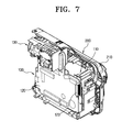
- the deck assembly 100 is fitted into the first exterior assembly 200 so as to be in a sub-assembled condition, as shown in Figure 7.
- the second exterior assembly 300 includes the second exterior frame 310, a display unit 320 connected to the second exterior frame 310, and a sub board 330.
- the second exterior frame 310 corresponds to the first exterior frame, and covers the other side of the deck assembly 100.
- a panel mounting part 311 is recessed in the second exterior frame 310 so that the LCD panel 321 can be located therein, which is described below.
- the display unit 320 includes an LCD panel 321 movably connected to the second exterior frame 310, and a viewfinder unit 325 engaged in the exterior frame 310.
- the LCD panel 321 is pivotable with respect to the second exterior frame 310 by certain angles with respect to the two perpendicular axes, x and y.
- the LCD panel 321 is housed in the panel mount part 311.
- the viewfinder unit 325 includes a viewfinder cover 326 engaged in the upper part of the second exterior frame 310, and a viewfinder 327 engaged with the viewfinder cover 326.
- the viewfinder 327 displays the image that is photographed or played back by the camera unit 130 in a known manner.
- the sub board 330 is engaged in the second exterior frame 310.
- the sub board 330 is connected to the LCD panel 321 and the viewfinder 327 to transmit signals thereto.
- the sub board 330 includes a plurality of connectors 331 and 332.
- the connectors 331 and 332 are connected to the connectors 121 and 122 on the main board 120 via the signal cables 335 and 336, before assembling the second exterior assembly 300 to the first exterior assembly 200.
- the front unit 400 includes a front frame 410, and a front board 420 engaged with the front frame 410.
- the front frame 410 covers the front part of the apparatus, in other words the deck assembly 100, at the same side as where the viewfinder unit 325 is located.
- the battery mount groove 412 has a terminal 411 facing outward of the front frame 410 to allow the battery to be mounted thereto.
- the front frame 410 is assembled with the first and second exterior frames 210 and 310.
- the front board 420 includes switches 421, 422 and 423 which correspond to a plurality of buttons allowing users to interact with the camcorder. Ports 425 and 426 are for inputting and outputting various signals.
- the front board 420 includes a connector 427 that is connected to the connector 123 (refer to Figure 2) of the main board 120, as shown in Figure 6.
- the front board 420 is directly connecting with the main board 120 (without using a separate signal cable) which allows the front board 420 to be supported by the main board 120.
- the rear unit 500 covers the rear side of the apparatus, in other words, is located on the same side as the camera unit 130.
- the rear unit 500 includes a rear frame 510 assembled with the first and second exterior frames 210 and 310.
- a microphone 520 is connected to the rear frame 510.
- the rear frame 510 includes an opening 511 on the upper side which allows the lens of the camera unit to be exposed.
- a plurality of holes are located in the lower part of the front facing side of rear frame 510 allowing sounds to be easily captured.
- the microphone 520 is located behind the holes, and is connected to the main board 120 using a cable (not shown).
- a camcorder according to an embodiment of the present invention is assembled by five modular units, as shown in Figure 1. Each unit is assembled to produce the finished camcorder. The assembly process is described below.
- assemblies 100, 200, 300, 400 and 500 are assembled and prepared as five modular units, as shown in Figure 1.
- the deck assembly 100 is first placed into the first exterior assembly 200. As shown in Figure 7, the deck assembly 100 is housed in the first exterior assembly 200, enclosing one side of the deck assembly.
- the deck unit 110 is assembled so that it is adjacent the first exterior frame 210 so that it may be accessed using the door 220 connected to the first exterior frame 210.
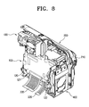
- the front unit 400 is connected to the first exterior frame 210, as shown in Figure 8.
- the connector 421 located on the front panel 420 is coupled to the connector 123 of the main board 120.
- the signal cables 335 and 336 Prior to connecting the second exterior assembly 300 to the first exterior assembly 100, the signal cables 335 and 336 are connected to the sub board 330 of the second exterior assembly 300 using connectors 121 and 122 of the main board 120. Therefore, the sub board 330 is connected to the main board 120. As described above, the boards 120 and 320 are connected, and then the second exterior assembly 300 is connected to the first exterior assembly 100, as shown in Figure 9.
- FIG. 10 are views of the camcorder having a battery 600 on the front unit 400.
- each part of the camcorder is divided into pre-assembled modular units which are assembled one by one. Therefore, simplifying the assembly process.
- each modular unit is assembled in predetermined process ensuring that correct connections are made between the main board and various parts, incorrect assembly is less likely to occur.
- the apparatus may be easily repaired and parts replaced as necessary.
Landscapes
- Engineering & Computer Science (AREA)
- General Engineering & Computer Science (AREA)
- Mechanical Engineering (AREA)
- Multimedia (AREA)
- Signal Processing (AREA)
- Physics & Mathematics (AREA)
- Electromagnetism (AREA)
- Studio Devices (AREA)
- Camera Bodies And Camera Details Or Accessories (AREA)
Applications Claiming Priority (2)
| Application Number | Priority Date | Filing Date | Title |
|---|---|---|---|
| KR2004013802 | 2004-02-28 | ||
| KR1020040013802A KR20050088002A (ko) | 2004-02-28 | 2004-02-28 | 영상촬영장치 및 그 조립방법 |
Publications (1)
| Publication Number | Publication Date |
|---|---|
| EP1569439A2 true EP1569439A2 (de) | 2005-08-31 |
Family
ID=34747972
Family Applications (1)
| Application Number | Title | Priority Date | Filing Date |
|---|---|---|---|
| EP05100644A Withdrawn EP1569439A2 (de) | 2004-02-28 | 2005-01-31 | Camcorder und Herstellungsverfahren dafür |
Country Status (5)
| Country | Link |
|---|---|
| US (1) | US20050190289A1 (de) |
| EP (1) | EP1569439A2 (de) |
| JP (1) | JP4061314B2 (de) |
| KR (1) | KR20050088002A (de) |
| CN (1) | CN1661460A (de) |
Family Cites Families (14)
| Publication number | Priority date | Publication date | Assignee | Title |
|---|---|---|---|---|
| AU638457B2 (en) * | 1989-05-30 | 1993-07-01 | Sony Corporation | Unified compact video camera and vcr |
| US5038213A (en) * | 1990-02-16 | 1991-08-06 | Kyocera Corporation | Electronic still camera |
| CA2130011C (en) * | 1993-08-24 | 2004-03-30 | Masayoshi Morikawa | Cassette eject mechanism, battery loading mechanism and mechanical chassis supporting mechanism |
| JP3932996B2 (ja) * | 2002-07-03 | 2007-06-20 | ソニー株式会社 | 電子機器 |
| US7123481B2 (en) * | 2002-12-26 | 2006-10-17 | Hitachi, Ltd. | Electronic device |
| JP2005189368A (ja) * | 2003-12-25 | 2005-07-14 | Hitachi Ltd | ビデオカメラ |
| KR20050090777A (ko) * | 2004-03-10 | 2005-09-14 | 삼성전자주식회사 | 영상촬영장치 |
| KR20050090802A (ko) * | 2004-03-10 | 2005-09-14 | 삼성전자주식회사 | 디지털 스틸 카메라 일체형 디지털 캠코더 및 그 제조방법 |
| KR20050090887A (ko) * | 2004-03-10 | 2005-09-14 | 삼성전자주식회사 | 영상촬영장치 및 그 조립방법 |
| JP4385327B2 (ja) * | 2004-07-30 | 2009-12-16 | 日本ビクター株式会社 | 情報処理装置 |
| JP4438737B2 (ja) * | 2005-11-14 | 2010-03-24 | 株式会社日立製作所 | 携帯型電子機器 |
| JP2007166289A (ja) * | 2005-12-14 | 2007-06-28 | Sony Corp | 撮像装置 |
| JP2007166291A (ja) * | 2005-12-14 | 2007-06-28 | Sony Corp | 撮像装置 |
| JP4089737B2 (ja) * | 2006-06-13 | 2008-05-28 | 株式会社日立製作所 | ビデオカメラ |
-
2004
- 2004-02-28 KR KR1020040013802A patent/KR20050088002A/ko not_active Withdrawn
-
2005
- 2005-01-31 EP EP05100644A patent/EP1569439A2/de not_active Withdrawn
- 2005-02-16 US US11/058,280 patent/US20050190289A1/en not_active Abandoned
- 2005-02-18 JP JP2005042709A patent/JP4061314B2/ja not_active Expired - Fee Related
- 2005-02-28 CN CN2005100086323A patent/CN1661460A/zh active Pending
Also Published As
| Publication number | Publication date |
|---|---|
| CN1661460A (zh) | 2005-08-31 |
| JP4061314B2 (ja) | 2008-03-19 |
| KR20050088002A (ko) | 2005-09-01 |
| US20050190289A1 (en) | 2005-09-01 |
| JP2005244970A (ja) | 2005-09-08 |
Similar Documents
| Publication | Publication Date | Title |
|---|---|---|
| KR20040032724A (ko) | 디지털 스틸 카메라 일체형 디지털 캠코더 | |
| US7423690B2 (en) | Image photographing apparatus and assembly method thereof | |
| JP2004120598A (ja) | 音響部品の保持構造および携帯型電子機器 | |
| CN100407769C (zh) | 具有一体的数码相机的数字摄像机及其制造方法 | |
| EP1569439A2 (de) | Camcorder und Herstellungsverfahren dafür | |
| CN220108097U (zh) | 主机模块和相机 | |
| KR100695075B1 (ko) | 듀얼렌즈 조립체 및 이를 구비한 영상촬영장치 | |
| CN100379261C (zh) | 图像拍摄装置 | |
| KR101001623B1 (ko) | 영상촬영장치 | |
| JP4662165B2 (ja) | 電子機器 | |
| JPH1132240A (ja) | 電子的撮像装置 | |
| US12470793B2 (en) | Integrated sensor-lens assemblies in image capture apparatuses and methods of assembling the same | |
| KR20050088003A (ko) | 영상촬영장치 | |
| JPH0486073A (ja) | 撮像装置 | |
| KR100678664B1 (ko) | 캠코더 | |
| JP2001053994A5 (ja) | 撮像装置 | |
| CN116828275A (zh) | 一种支撑座、摄像头模组、图像获取装置及功能设备 | |
| JP2005078861A (ja) | 電子機器 | |
| JPH01227578A (ja) | 電子スチルカメラ | |
| JP2006352760A (ja) | 撮像装置 | |
| JP2005204236A (ja) | 撮影装置 | |
| JPH08223461A (ja) | 電子スチルカメラ | |
| JPH08317260A (ja) | ビデオカメラ装置 | |
| JPH07307886A (ja) | ビデオカメラ |
Legal Events
| Date | Code | Title | Description |
|---|---|---|---|
| PUAI | Public reference made under article 153(3) epc to a published international application that has entered the european phase |
Free format text: ORIGINAL CODE: 0009012 |
|
| AK | Designated contracting states |
Kind code of ref document: A2 Designated state(s): AT BE BG CH CY CZ DE DK EE ES FI FR GB GR HU IE IS IT LI LT LU MC NL PL PT RO SE SI SK TR |
|
| AX | Request for extension of the european patent |
Extension state: AL BA HR LV MK YU |
|
| STAA | Information on the status of an ep patent application or granted ep patent |
Free format text: STATUS: THE APPLICATION HAS BEEN WITHDRAWN |
|
| 18W | Application withdrawn |
Effective date: 20090112 |