EP1569362B1 - Funkempfangsgerät und funkempfangsverfahren - Google Patents
Funkempfangsgerät und funkempfangsverfahren Download PDFInfo
- Publication number
- EP1569362B1 EP1569362B1 EP20030775882 EP03775882A EP1569362B1 EP 1569362 B1 EP1569362 B1 EP 1569362B1 EP 20030775882 EP20030775882 EP 20030775882 EP 03775882 A EP03775882 A EP 03775882A EP 1569362 B1 EP1569362 B1 EP 1569362B1
- Authority
- EP
- European Patent Office
- Prior art keywords
- section
- signal component
- signals
- propagation path
- absolute value
- Prior art date
- Legal status (The legal status is an assumption and is not a legal conclusion. Google has not performed a legal analysis and makes no representation as to the accuracy of the status listed.)
- Expired - Lifetime
Links
Images

Classifications
-
- H—ELECTRICITY
- H04—ELECTRIC COMMUNICATION TECHNIQUE
- H04B—TRANSMISSION
- H04B7/00—Radio transmission systems, i.e. using radiation field
- H04B7/02—Diversity systems; Multi-antenna system, i.e. transmission or reception using multiple antennas
- H04B7/04—Diversity systems; Multi-antenna system, i.e. transmission or reception using multiple antennas using two or more spaced independent antennas
- H04B7/08—Diversity systems; Multi-antenna system, i.e. transmission or reception using multiple antennas using two or more spaced independent antennas at the receiving station
- H04B7/0868—Hybrid systems, i.e. switching and combining
- H04B7/0871—Hybrid systems, i.e. switching and combining using different reception schemes, at least one of them being a diversity reception scheme
-
- H—ELECTRICITY
- H04—ELECTRIC COMMUNICATION TECHNIQUE
- H04B—TRANSMISSION
- H04B7/00—Radio transmission systems, i.e. using radiation field
- H04B7/02—Diversity systems; Multi-antenna system, i.e. transmission or reception using multiple antennas
- H04B7/04—Diversity systems; Multi-antenna system, i.e. transmission or reception using multiple antennas using two or more spaced independent antennas
- H04B7/0413—MIMO systems
Definitions
- the present invention relates to a wireless receiver which receives data transmitted in parallel from a plurality of transmitting antennas with a plurality of receiving antennas, and a wireless reception method employed in such an apparatus.
- MIMO communication Multi-Input/Multi-Output (MIMO) communication has been drawing an attention as a technology for enabling a communication of massive data such as images.
- MIMO communication different transmitted data (sub streams) are respectively transmitted from a plurality of antennas in a transmitter side, and a plurality of the transmitted data that are mixed in a propagation path are separated into the respective original transmitted data in a receiver side by using a propagation path estimate (see, for example, Japanese Patent Publication No. 2002-44051 ( FIG.4 )).
- signal transmitted from a transmission apparatus is received with the antennas, the number of which is equal to or larger than the number of the transmission apparatuses, and the propagation path characteristics between antennas are estimated based on pilot signals, which are respectively inserted into signals received with the respective antennas.
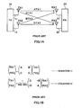
- This estimated propagation path characteristic H is represented by a matrix of 2 x 2, where, for example, number of the transmitting antennas is two and number of the receiving antenna is two.
- transmission signals (sub streams) transmitted by respective transmitting antennas are found.
- the received signals (RX1, RX2) can be expressed with (equation 1) shown in FIG.1B .
- A represents a propagation path characteristic between the transmitting antenna 11 and the receiving antenna
- B represents a propagation path characteristic between the transmitting antenna 12 and the receiving antenna
- C represents a propagation path characteristic between the transmitting antenna 11 and the receiving antenna 22
- D represents a propagation path characteristic between the transmitting antenna 12 and the receiving antenna 22.
- the signal is received in a form of a mixed combination of TX1 and TX2, as expressed in (equation 1).
- TX1 and TX2 are defined as a desired signal component and the other is defined as an interference signal component, and the interference signal component should be compensated.
- the transmitter 10 transmits the signal containing a known signal for propagation path estimation (pilot signal, for example) inserted in the transmission signal, and the receiver 20 conducts a propagation path estimation based on this known signal to obtain the propagation path characteristics A, B, C and D, thereby finding the above-described inverse matrix.
- Procedures for actually finding the transmission signal (TX1, TX2) from the received signal (RX1, RX2) includes: a Zero-Forcing (ZF) arithmetic operation for separating a sub stream (respective data) by using only an inverse matrix arithmetic operation presented by (equation 2), or Minimum Mean Square Error (MMSE) arithmetic operation for separating so as to minimize an error, and the like.
- ZF Zero-Forcing
- MMSE Minimum Mean Square Error
- of the inverse matrix represented in FIG.1B may be closer to zero, and since the conventional apparatus attempts to compensate for the interference signal component even in such situation another problem occurs that an interference compensation error in the separated desired signal becomes greater, thereby significantly deteriorating the error rate in the receiving side.
- An object of the present invention is to improve an error rate characteristic in the receiving side even under the environment, in which an interference compensation error becomes larger in the receiving side, when different data are transmitted between a plurality of transmitting antennas and a plurality of receiving antennas respectively as in the MIMO communication.
- Embodiments of the present invention will be described in reference to the annexed figures as follows. While the description is made in reference to a case of, for example, performing a MIMO communication by using two antennas for either of the transmitting and receiving sides, respectively, the present invention can also be applied for a case having an arbitrary number of antennas.
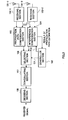
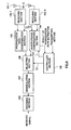
- FIG.2 is a block diagram, illustrating a configuration of a wireless receiver according to a first embodiment of the present invention.
- a wireless receiver shown in FIG. 2 comprises receiving antennas 101, receiving sections 102, a propagation path compensation section 103, an interference compensation section 104, a controller section 105, a selecting section 106, a demodulating section 107 and a decoding section 108.
- a receiving section 102-1 performs a predetermined wireless receiving processing such as a down-converting and the like over a signal that is received through a receiving antenna 101-1, and then output thereof to the propagation path compensation section 103 and the interference compensation section 104.
- a receiving section 102-2 performs a predetermined wireless receiving processing such as a down-converting and the like over a signal that is received through a receiving antenna 101-2, and then output thereof to the propagation path compensation section 103 and the interference compensation section 104.
- the propagation path compensation section 103 performs propagation path estimations (channel estimations) for the signals output from the receiving sections 102-1 and 102-2, and a propagation path compensation (channel variation compensation) is conducted on the basis of the results, and then the resultant signals are output to the selecting section 106.
- the "propagation path estimation” means estimating a magnitude of a propagation path variation (channel variation) influenced by fading or the like in a propagation path after the radio signal is transmitted from the transmitting side till arriving at the receiving antenna of the receiving side.
- the "propagation path compensation” means, for example, complex-multiplying a predetermined vector into the original signal in order to remove (compensate) the influence of the propagation path variation based on the results of the propagation path estimation (channel estimation value).
- the interference compensation section 104 performs similar propagation path estimation for the signals output from the receiving sections 102-1, 102-2 as the propagation path compensation section 103 performs and output this results to the controller section 105, and also performs the previously explained MIMO separation processing and output the separated received signals to the selecting section 106.
- the selecting section 106 selects one of the signals output from the propagation path compensation section 103 and the interference compensation section 104 under the control of the controller section 105, and output thereof to a demodulating section 107. The details of the control conducted by the controller section 105 will be discussed later.
- the demodulating section 107 performs a predetermined demodulating processing for the signal output from the selecting section 106 corresponding to a modulation system such as Quadrature Phase Shift Keying (QPSK), 16 Quadrature Amplitude Modulation (16QAM) used in the transmitting side, and output the processed signal to a decoding section 108.
- a modulation system such as Quadrature Phase Shift Keying (QPSK), 16 Quadrature Amplitude Modulation (16QAM) used in the transmitting side
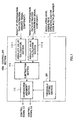
- FIG.3 is a block diagram, illustrating an internal structure of the controller section 105.
- the controller section 105 comprises an absolute value calculation section 111, a subtraction section 112 and a comparative judgement section 113.
- the result of the propagation path estimation which is output from the interference compensation section 104, includes a desired signal component and an interference signal component, as mentioned above.
- the absolute value calculation section 111-1 calculates an absolute value of the desired signal component in the result of the propagation path estimation output from the interference compensation section 104, and output thereof to the subtraction section 112.
- the absolute value calculation section 111-2 calculates an absolute value of the interference signal component in the result of the propagation path estimation output from the interference compensation section 104, and output thereof to the subtraction section 112.
- the subtraction section 112 subtracts the absolute value of the interference signal component (output of the absolute value calculation section 111-2) from the absolute value of the desired signal component (output of the absolute value calculation section 111-1), and output the obtained difference to the comparative judgement section 113.
- Comparative judgement section 113 compares the difference output from the subtraction section 112 with a predetermined threshold, and instructs (outputs a control signal C1 to) the selecting section 106 to select an output of the interference compensation section 104 when the difference is smaller than the threshold. In addition, when difference is equal to or larger than the threshold, the control signal C1 is output to the selecting section 106 so as to select the output of the propagation path compensation section 103.
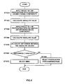
- the desired signal component of the result of the propagation path estimation output from the interference compensation section 104 is input into the absolute value calculation section 111-1 (ST1010).
- the Absolute value calculation section 111-1 calculates an absolute value of the result of the propagation path estimation (ST1020).
- the interference signal component of the result of the propagation path estimation output by the interference compensation section 104 is input into the absolute value calculation section 111-2 (ST1030).
- the absolute value calculation section 111-2 calculates an absolute value of the result of the propagation path estimation (ST1040).
- the subtraction section 112 finds a difference between the absolute value of the desired signal component and the absolute value of the interference signal component (ST1050).
- the calculated difference indicates how relatively large the propagation path variation generated in the desired signal component is, as compared with the propagation path variation generated in the interference signal component.
- larger difference indicates that the propagation path variation generated in the desired signal component is larger than the propagation path variation generated in the interference signal component.
- Comparative judgement section 113 compares the difference output from the subtraction section 112 with a predetermined threshold (ST1060), and outputs an instruction (control signal) to the selecting section 106 to select an output of the interference compensation section 104 when the difference is smaller than the threshold (ST1070) .
- the instruction (control signal) is output to the selecting section 106 so as to select the output of the propagation path compensation section 103 (ST1080).
- the operation is performed that, when the level of the propagation path variation generated in the desired signal component is equivalent to the level of the propagation path variation generated in the interference signal component, a signal, which is processed by the separation processing via a MIMO technique, is selected, and when the level of the propagation path variation generated in the interference signal component is much smaller than the level of the propagation path variation generated in the desired signal component, a signal, which is processed by a simple propagation path compensation, is selected.
- the controller section 105 While it is illustrated here that two inputs are included in the controller section 105 in order to simplify the description, four inputs are actually included in the controller section 105 as described above, since the desired signal component and the interference signal component of the result of the propagation path estimation exist in respective receiving antennas. In this occasion, for example, if every two inputs corresponding to respective receiving antennas are handled via a time division, two results of the threshold determination can be obtained. In such case, in either of the determination results, the output of the propagation path compensation section 103 may be selected only in the case where the difference calculated in the subtraction section 112 is equal to or higher than the threshold. In addition, each of the determination results may be reflected for every receiving antenna. More specifically, the operation may be performed, in which the signal processed by the propagation path compensation processing is selected as the signal received by the receiving antenna 101-1, and the signal processed by interference compensation processing is selected as the signal received by the receiving antenna 101-2.
- ratio of absolute values of propagation path estimate of the desired signal and the interference signal may be calculated, and the obtained ratio may be compared with the threshold.
- a benefit of presenting smaller scale of the hardware can be provided when the procedure for utilizing the difference is selected.
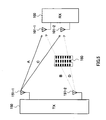
- the controller section 105 output the control signal C2 to the interference compensation section 104 so as to stop the rest of the interference compensation processing except for the propagation path estimation processing, when the propagation path compensation section 103 is selected. Having this configuration, since the electric power consumed by the interference compensation section 104 is considerably large, an effect of cutting the power consumption can be expected. Here, it is needless to say that, when the interference compensation section 104 is selected, a function for instructing a stop to the propagation path compensation section 103 may be installed. Next, advantageous effects obtainable by the wireless receiver having the above-described configuration will be specifically described by using FIG.5 .
- the radio signal transmitted from the transmitting antenna 151-1 is received in the receiver side at stronger signal intensity than the signal intensity, at which the radio signal transmitted from the transmitting antenna 151-2 is received.
- inMIMO communication for example, it may often be the case that respective transmitting antennas are dedicated to respective users (respective transmission counterparts).
- the signal transmitted from the transmitting antenna 151-1 is a signal for the wireless receiver 100
- the signal transmitted from the transmitting antenna 151-2 is a signal not for the wireless receiver 100.
- an inverse matrix of a matrix representing the propagation path characteristic is found by additionally aiming the signal transmitted from the transmitting antenna 151-2 (or by dealing with the signals except a desired signal as an interference component), and then the interference component is removed by multiplying this inverse matrix to separate (MIMO-separation) the signals transmitted by the two transmitting antennas.
- the wireless receiver according to the present embodiment conducts the processing of the propagation path compensation for only the signal transmitted from the transmitting antenna 151-1 by switching the two circuits without conducting the MIMO separation processing to obtain the received signal.
- this processing correspond treating the signal transmitted from the transmitting antenna 151-2 as mere noise and not as interference component.
- the embodiment described above is presented under the considerably limited situation, as general consideration, the situation, in which the received signal strength of the interference signal component is considerably lower as relatively compared with the desired signal component, is easily caused, when the desired signal component of the signal received from the receiving antenna is compared with the interference signal component.
- the receiving side select one of the propagation path compensation section and the interference compensation section, and therefore the error rate characteristics in the receiving side can be improved even in the situation where the interference compensation error is larger.
- the interference compensation algorithm also includes other algorithms (for example, maximum likelihood sequence estimation) and it is needless to point out that other interference compensation algorithm may also be applied thereto. Also, as shown in FIG. 6 , switching between the propagation path compensation section 103 and the interference compensation section 104 may be conducted by informing the controller section 105 of the transmission method utilized in the transmitting side.
- the controller section 105 can transmit an indication to the selecting section 106 so as to select the propagation path compensation section 103.
- FIG.7 is a block diagram, illustrating a configuration of a controller section of a wireless receiver according to the second embodiment of the present invention.
- the threshold setting section 201 is informed of a modulation level, a coding rate, a spreading factor, or a code multiplex number used for transmission signal, and sets a threshold used in the comparative judgement section 113 based on these values.
- the QPSK modulation system has better error resistance as compared with 16QAM modulation system when the propagation path environment is deteriorated.
- the QPSK is employed, by performing the propagation path compensation for the received signal, a probability for obtaining the data containing no error becomes higher than the case the 16QAM is employed as modulation system.
- the reference (threshold) for selecting one of the propagation path compensation section 103 and the interference compensation section 104 in response to the modulation system of the transmission signal (modulation level). Having this configuration, the case of stopping the operation of the interference compensation section 104 by selecting the propagation path compensation section 103 is more frequently occurred, and therefore the power consumption of the wireless receiver is reduced.
- the threshold setting section 201 sets the threshold used in the comparative judgement section 113 by suitably changing thereof, in response to the modulation levels used for the transmission signal.
- the modulation levels mentioned above may be informed from the transmitting side, or obtained by analyzing the signal received from the receiver side to provide the modulation level or the like.
- the switching reference used for the transmission signal is changed according to modulation level or the like when one of the propagation path compensation section and the interference compensation section is switched to be employed in the receiving side, and therefore the case of selecting the propagation path compensation section is more frequently occurred to provide reduced power consumption of the wireless receiver.
- the wireless receiver according to the present invention is capable of being installed in the communication terminal apparatus and the base station apparatus in the mobile radio communication system, and this can provide the communication terminal and the base station apparatus having advantageous effects similar to the above-described advantageous effects. Further, the wireless receiver according to the present invention can be utilized in the mobile radio communication system that utilizes a multi-carrier system such as Orthogonal Frequency Division Multiplex (OFDM) or the like, and this can provide the mobile radio communication system having advantageous effects similar to the above-described advantageous effects. Since the transmission system employing the multi-carrier is set to have lower symbol rate (long symbol length), there is an advantageous effect of reducing the inter-code interference by the multipath in the multipath environment.
- OFDM Orthogonal Frequency Division Multiplex
- inter-code interference by multipath can also be removed by inserting the guard interval.
- the error rate characteristic in the receiving side even under the environment, in which the interference compensation error becomes larger in the receiving side can be improved in the case of transmitting different data between a plurality of transmitting antennas and a plurality of receiving antennas respectively as in the MIMO communication.
- the present invention can be applied to a wireless receiver, which receives data transmitted in parallel from a plurality of transmitting antenna by employing a plurality of receiving antenna, and a wireless reception method employed in such apparatus.
Landscapes
- Engineering & Computer Science (AREA)
- Computer Networks & Wireless Communication (AREA)
- Signal Processing (AREA)
- Radio Transmission System (AREA)
- Mobile Radio Communication Systems (AREA)
Claims (6)
- MIMO-Empfänger (Multiple-Input/Multiple-Output receiver), der umfasst einen Empfangsabschnitt (102), der so eingerichtet ist, dass er eine Vielzahl von Funksignalen unter Verwendung einer Vielzahl von Empfangsantennen (101) empfängt;
einen Ausbreitungsweg-Kompensationsabschnitt (103), der so eingerichtet ist, dass er Kanalschwankungs-Kompensationen für die Vielzahl von Funksignalen durchführt, um die kompensierten Signale zu gewinnen; und
einen Interferenz-Kompensationsabschnitt (104), der so eingerichtet ist, dass er die jeweiligen Funksignale über eine MIMO-Trennungsverarbeitung trennt, um die getrennten Signale zu gewinnen, die eine erwünschte Signalkomponente und eine Interferenz-Signalkomponente enthalten,
dadurch gekennzeichnet, dass
der MIMO-Empfänger des Weiteren umfasst:einen Auswählabschnitt (106), der so eingerichtet ist, dass er zwischen den kompensierten Signalen und den getrennten Signalen auswählt;einen Absolutwert-Berechnungsabschnitt (111-1, 111-2), der so eingerichtet ist, dass er einen Absolutwert der erwünschten Signalkomponente und einen Absolutwert der Interferenz-Signalkomponente berechnet;einen Subtrahierabschnitt (112), der so eingerichtet ist, dass er eine Differenz zwischen dem Absolutwert der erwünschten Signalkomponente und dem Absolutwert der Interferenz-Signalkomponente ermittelt; undeinen Steuerabschnitt (105), der so eingerichtet ist, dass er den Auswählabschnitt (106) so steuert, dass der Auswählabschnitt (106) die kompensierten Signale in dem Fall auswählt in dem die Differenz einem Schwellenwert gleich ist oder größer als dieser, und den Auswählabschnitt (106) so steuert, dass der Auswählabschnitt (106) die getrennten Signale in dem Fall auswählt, in dem die Differenz kleiner ist als der Schwellenwert. - MIMO-Empfänger nach Anspruch 1, der des Weiteren umfasst:einen Festlegeabschnitt, der so eingerichtet ist, dass er den Schwellenwert auf Basis einer Modulationsstufe, einer Codierrate, eines Spreizfaktors oder einer Code-Multiplex-Nummer des Funksignals festlegt.
- MIMO-Empfänger nach Anspruch 1, wobei das Funksignal in einen Mehrfachträger umgewandelt wird.
- Kommunikations-Endgerätvorrichtung, die den MIMO-Empfänger nach Anspruch 1 umfasst.
- Basisstations-Vorrichtung, die den MIMO-Empfänger nach Anspruch 1 umfasst.
- MIMO-Empfangsverfahren (Multiple-Input/Multiple-Output reception method), das die folgenden Schritte umfasst
Empfangen einer Vielzahl von Funksignalen unter Verwendung einer Vielzahl von Empfangsantennen;
Durchführen von Kanalschwankungs-Kompensationen für die Vielzahl von Funksignalen, um die kompensierten Signale zu gewinnen; und
Trennen der jeweiligen Funksignale über eine MIMO-Trennverarbeitung, um die getrennten Signale zu gewinnen, die eine erwünschte Signalkomponente und eine Interferenz-Signalkomponente enthalten,
dadurch gekennzeichnet, dass
das MIMO-Empfangsverfahren des Weiteren die folgenden Schritte umfasst:Berechnen eines Absolutwertes der erwünschten Signalkomponente und eines Absolutwertes der Interferenz-Signalkomponente;Ermitteln einer Differenz zwischen dem Absolutwert der erwünschten Signalkomponente und dem Absolutwert der Interferenz-Signalkomponente;Auswählen der kompensierten Signale in dem Fall, in dem die Differenz einem Schwellenwert gleich ist oder größer als dieser, und Auswählen der getrennten Signale in dem Fall, in dem die Differenz kleiner ist als der Schwellenwert, aus den kompensierten Signalen und den getrennten Signalen.
Applications Claiming Priority (3)
| Application Number | Priority Date | Filing Date | Title |
|---|---|---|---|
| JP2002341741 | 2002-11-26 | ||
| JP2002341741A JP3629261B2 (ja) | 2002-11-26 | 2002-11-26 | 無線受信装置 |
| PCT/JP2003/015059 WO2004049597A1 (ja) | 2002-11-26 | 2003-11-26 | 無線受信装置および無線受信方法 |
Publications (3)
| Publication Number | Publication Date |
|---|---|
| EP1569362A1 EP1569362A1 (de) | 2005-08-31 |
| EP1569362A4 EP1569362A4 (de) | 2005-12-28 |
| EP1569362B1 true EP1569362B1 (de) | 2011-10-26 |
Family
ID=32375864
Family Applications (1)
| Application Number | Title | Priority Date | Filing Date |
|---|---|---|---|
| EP20030775882 Expired - Lifetime EP1569362B1 (de) | 2002-11-26 | 2003-11-26 | Funkempfangsgerät und funkempfangsverfahren |
Country Status (6)
| Country | Link |
|---|---|
| US (2) | US7299027B2 (de) |
| EP (1) | EP1569362B1 (de) |
| JP (1) | JP3629261B2 (de) |
| CN (1) | CN1714519B (de) |
| AU (1) | AU2003284446A1 (de) |
| WO (1) | WO2004049597A1 (de) |
Cited By (1)
| Publication number | Priority date | Publication date | Assignee | Title |
|---|---|---|---|---|
| US9374139B2 (en) | 2002-04-22 | 2016-06-21 | Ipr Licensing, Inc. | Multiple-input multiple-output radio transceiver |
Families Citing this family (27)
| Publication number | Priority date | Publication date | Assignee | Title |
|---|---|---|---|---|
| GB0222555D0 (en) | 2002-09-28 | 2002-11-06 | Koninkl Philips Electronics Nv | Packet data transmission system |
| JP2005167873A (ja) * | 2003-12-05 | 2005-06-23 | Pioneer Electronic Corp | 受信機、受信方法、受信制御用プログラム及び記録媒体 |
| US20060034271A1 (en) * | 2004-08-16 | 2006-02-16 | Texas Instruments Incorporated | Packet detection system and method for packet-based wireless receivers having multiple receive chains |
| US20060128310A1 (en) * | 2004-12-14 | 2006-06-15 | Michael Leabman | Transmit/receive compensation in smart antenna systems |
| US7489910B2 (en) | 2005-03-30 | 2009-02-10 | Kabushiki Kaisha Toshiba | Wireless transmitter and amplifier |
| CN100557988C (zh) * | 2005-07-05 | 2009-11-04 | 华为技术有限公司 | 降低频率复用率的无线通信系统 |
| US8223904B2 (en) * | 2005-08-22 | 2012-07-17 | Qualcomm Incorporated | Multiple hypothesis decoding |
| KR100810231B1 (ko) * | 2005-09-28 | 2008-03-06 | 삼성전자주식회사 | 무선 통신 시스템에서 다중 안테나를 이용한 신호 송신방법 및 장치 |
| JP4504293B2 (ja) * | 2005-09-29 | 2010-07-14 | 株式会社東芝 | 複数アンテナを備えた無線通信装置および無線通信システム、無線通信方法 |
| US8467462B2 (en) * | 2005-11-16 | 2013-06-18 | Sharp Kabushiki Kaisha | Multicarrier receiving apparatus, multicarrier communication system and demodulation method |
| JP4744351B2 (ja) * | 2006-04-28 | 2011-08-10 | 富士通株式会社 | 無線送信局及び無線受信局 |
| KR101002800B1 (ko) * | 2006-06-09 | 2010-12-21 | 삼성전자주식회사 | 무선 이동 통신 시스템에서 공통 제어 정보 송신 방법 |
| US8098720B2 (en) * | 2006-10-06 | 2012-01-17 | Stmicroelectronics S.R.L. | Method and apparatus for suppressing adjacent channel interference and multipath propagation signals and radio receiver using said apparatus |
| US8805282B2 (en) * | 2007-02-16 | 2014-08-12 | Nec Corporation | Radio transmission system and interference compensation method |
| EP2219310A4 (de) | 2007-11-30 | 2014-02-19 | Nec Corp | Drahtloses kommunikationssystem, empfänger, sender, drahtloses kommunikationsverfahren, empfangsverfahren und sendeverfahren |
| US8134912B2 (en) * | 2008-10-20 | 2012-03-13 | Intel Corporation | Apparatus, systems and methods adapted for opportunistic forwarding of uplink short messages in wireless metropolitan area networks |
| US8023921B2 (en) * | 2008-12-03 | 2011-09-20 | Bae Systems Information And Electronic Systems Integration Inc. | Quadratic amplitude control circuit for cosite interference cancellation |
| JP5288622B2 (ja) * | 2009-06-16 | 2013-09-11 | シャープ株式会社 | 無線通信装置、無線通信システムおよび通信方法 |
| KR101667030B1 (ko) * | 2009-08-10 | 2016-10-17 | 삼성전자 주식회사 | 로봇의 경로 계획 장치 및 그 방법 |
| US8306483B2 (en) * | 2009-12-24 | 2012-11-06 | Intel Corporation | Method and system for improving wireless link robustness using spatial diversity |
| US8888701B2 (en) * | 2011-01-27 | 2014-11-18 | Valencell, Inc. | Apparatus and methods for monitoring physiological data during environmental interference |
| JP5720058B2 (ja) | 2011-04-25 | 2015-05-20 | 株式会社レイトロン | Mimo検出装置 |
| US10284267B2 (en) | 2016-03-11 | 2019-05-07 | Huawei Technologies Canada Co., Ltd. | System and method for reducing self-interference in a wireless resource |
| US10847879B2 (en) | 2016-03-11 | 2020-11-24 | Huawei Technologies Canada Co., Ltd. | Antenna array structures for half-duplex and full-duplex multiple-input and multiple-output systems |
| JP7063751B2 (ja) * | 2018-07-13 | 2022-05-09 | 日本放送協会 | 放送信号受信装置 |
| JP7722815B2 (ja) * | 2020-10-15 | 2025-08-13 | トヨタ自動車株式会社 | 無線通信制御方法、受信局、及びプログラム |
| JPWO2024247234A1 (de) * | 2023-06-01 | 2024-12-05 |
Family Cites Families (32)
| Publication number | Priority date | Publication date | Assignee | Title |
|---|---|---|---|---|
| US53143A (en) * | 1866-03-13 | Improvement in shaft-couplings | ||
| US5390342A (en) * | 1990-03-14 | 1995-02-14 | Pioneer Electronic Corporation | Receiver using selective diversity receiving system |
| JP2643614B2 (ja) * | 1991-02-22 | 1997-08-20 | 日本電気株式会社 | ディジタル移動通信端末装置 |
| FR2701178A1 (fr) | 1993-02-03 | 1994-08-05 | Philips Electronique Lab | Système de communication par étalement de spectre à multiutilisateurs. |
| US5487091A (en) * | 1993-08-13 | 1996-01-23 | Motorola, Inc. | Method for determining signal usability in a diversity receiver |
| US5440590A (en) * | 1993-11-01 | 1995-08-08 | Motorola, Inc. | Method and apparatus for producing a usable signal from received diverse modulated signals |
| US5553102A (en) * | 1994-12-01 | 1996-09-03 | Motorola, Inc. | Diversity reception communication system with maximum ratio combining method |
| US5940452A (en) * | 1995-11-29 | 1999-08-17 | Motorola, Inc. | Dual mode radio subscriber unit having a diversity receiver apparatus and method therefor |
| JP3795984B2 (ja) * | 1996-12-20 | 2006-07-12 | 富士通株式会社 | 無線受信機 |
| US7116959B1 (en) * | 1997-09-30 | 2006-10-03 | Harman Becker Automotive Systems Gmbh | Apparatus for selecting a receiver among a plurality of receivers in a diversity receiver system based upon automatic gain correction |
| JPH11289211A (ja) | 1998-03-31 | 1999-10-19 | Toyota Central Res & Dev Lab Inc | アダプティブ受信装置 |
| US6181754B1 (en) * | 1998-06-12 | 2001-01-30 | Cadence Design Systems, Inc. | System and method for modeling mixed signal RF circuits in a digital signal environment |
| US6154485A (en) * | 1998-10-19 | 2000-11-28 | Motorola, Inc. | Receiver in a wireless communications system for receiving signals having combined orthogonal transmit diversity and adaptive array techniques |
| JP2000224139A (ja) | 1999-02-01 | 2000-08-11 | Sony Corp | ダイバーシチ受信装置 |
| JP3678944B2 (ja) | 1999-07-02 | 2005-08-03 | 松下電器産業株式会社 | 無線通信装置および無線通信方法 |
| US6377636B1 (en) * | 1999-11-02 | 2002-04-23 | Iospan Wirless, Inc. | Method and wireless communications system using coordinated transmission and training for interference mitigation |
| US7068628B2 (en) | 2000-05-22 | 2006-06-27 | At&T Corp. | MIMO OFDM system |
| JP2001358624A (ja) * | 2000-06-14 | 2001-12-26 | Sony Corp | 受信装置 |
| JP3699883B2 (ja) | 2000-06-29 | 2005-09-28 | 松下電器産業株式会社 | 無線基地局装置及び無線通信方法 |
| JP3421314B2 (ja) | 2000-10-04 | 2003-06-30 | 松下電器産業株式会社 | パス選択装置及びパス選択方法 |
| KR100510434B1 (ko) * | 2001-04-09 | 2005-08-26 | 니폰덴신뎅와 가부시키가이샤 | Ofdm신호전달 시스템, ofdm신호 송신장치 및ofdm신호 수신장치 |
| US6751187B2 (en) * | 2001-05-17 | 2004-06-15 | Qualcomm Incorporated | Method and apparatus for processing data for transmission in a multi-channel communication system using selective channel transmission |
| US20020193146A1 (en) * | 2001-06-06 | 2002-12-19 | Mark Wallace | Method and apparatus for antenna diversity in a wireless communication system |
| US20030048753A1 (en) * | 2001-08-30 | 2003-03-13 | Ahmad Jalali | Method and apparatus for multi-path elimination in a wireless communication system |
| CA2415170C (en) * | 2001-12-28 | 2008-07-15 | Ntt Docomo, Inc. | Receiver, transmitter, communication system, and method of communication |
| US7224704B2 (en) * | 2002-04-01 | 2007-05-29 | Texas Instruments Incorporated | Wireless network scheduling data frames including physical layer configuration |
| CN1572080B (zh) * | 2002-04-09 | 2011-04-06 | 松下移动通信株式会社 | 正交频分多路复用通信方法与正交频分多路复用通信装置 |
| US6904081B2 (en) | 2002-08-30 | 2005-06-07 | Motorola, Inc. | Spread spectrum receiver apparatus and method |
| JP4444779B2 (ja) * | 2004-10-12 | 2010-03-31 | リンナイ株式会社 | リモコン装置 |
| US7224269B2 (en) * | 2004-12-15 | 2007-05-29 | Ford Global Technologies, Llc | Method and system for resetting tire pressure monitoring system for an automotive vehicle |
| EP1845636A4 (de) * | 2005-02-03 | 2012-03-14 | Fujitsu Ltd | Drahtloses kommunikationssystem und drahtloses kommunikationsverfahren |
| US7558223B2 (en) * | 2005-04-04 | 2009-07-07 | Panasonic Corporation | OFDM receiving method of OFDM receiver for receiving an OFDM signal via a plurality of space paths |
-
2002
- 2002-11-26 JP JP2002341741A patent/JP3629261B2/ja not_active Expired - Fee Related
-
2003
- 2003-11-26 EP EP20030775882 patent/EP1569362B1/de not_active Expired - Lifetime
- 2003-11-26 WO PCT/JP2003/015059 patent/WO2004049597A1/ja not_active Ceased
- 2003-11-26 US US10/536,010 patent/US7299027B2/en not_active Expired - Lifetime
- 2003-11-26 AU AU2003284446A patent/AU2003284446A1/en not_active Abandoned
- 2003-11-26 CN CN2003801038379A patent/CN1714519B/zh not_active Expired - Fee Related
-
2007
- 2007-09-21 US US11/859,550 patent/US20080020802A1/en not_active Abandoned
Cited By (1)
| Publication number | Priority date | Publication date | Assignee | Title |
|---|---|---|---|---|
| US9374139B2 (en) | 2002-04-22 | 2016-06-21 | Ipr Licensing, Inc. | Multiple-input multiple-output radio transceiver |
Also Published As
| Publication number | Publication date |
|---|---|
| US20060063491A1 (en) | 2006-03-23 |
| EP1569362A1 (de) | 2005-08-31 |
| JP2004179822A (ja) | 2004-06-24 |
| CN1714519B (zh) | 2011-05-04 |
| US7299027B2 (en) | 2007-11-20 |
| CN1714519A (zh) | 2005-12-28 |
| AU2003284446A1 (en) | 2004-06-18 |
| EP1569362A4 (de) | 2005-12-28 |
| WO2004049597A1 (ja) | 2004-06-10 |
| US20080020802A1 (en) | 2008-01-24 |
| JP3629261B2 (ja) | 2005-03-16 |
Similar Documents
| Publication | Publication Date | Title |
|---|---|---|
| EP1569362B1 (de) | Funkempfangsgerät und funkempfangsverfahren | |
| EP1494381B1 (de) | Ofdm-kommunikationsverfahren und ofdm-kommunikationseinrichtung | |
| US7995536B2 (en) | Multi-input multi-output (MIMO) for wireless transmitting and receiving stations | |
| KR100737773B1 (ko) | 채널 추정 장치, 채널 추정 방법 및 무선 수신기 | |
| EP1798874B1 (de) | Mobilstationsvorrichtung und verfahren zur auswahl des kommunikationspartners | |
| EP1860789A1 (de) | Kommunikationseinrichtung und kommunikationsverfahren | |
| EP1505758A1 (de) | Verfahren und Vorrichtung zur Bestimmung eines Antennen-Mischmusters in einem DSTTD System | |
| US7796680B2 (en) | Mobile communication system and wireless apparatus to be used for the same | |
| KR20020026605A (ko) | 무선 기지국 장치 및 무선 통신 방법 | |
| EP1759470A1 (de) | Vorrichtung und verfahren zur strahlformung in einem mehrantennensystem | |
| KR101003373B1 (ko) | 다중 안테나 통신시스템에서 간섭 제거 장치 및 방법 | |
| JPWO2006075732A1 (ja) | 無線通信装置 | |
| EP1845634B1 (de) | Verfahren und System für geregelte Diversitätsverarbeitung mittels dediziertem Pilotkanal | |
| US8942325B2 (en) | Wireless communication apparatus and communication method | |
| EP1838020A1 (de) | Frequenzmultiplex-kommunikationssystem | |
| US8611481B2 (en) | Blind control channel detection | |
| WO2008129427A2 (en) | Method for transmitting and estimating symbols coded with a coding matrix, and corresponding receiver and transmitter | |
| JP5340344B2 (ja) | 通信装置及び通信方法 | |
| EP2654257B1 (de) | Verfahren und Vorrichtung zur Blinderkennung eines sekundären Pilotsignals in einem drahtlosen Kommunikationssystem | |
| KR100577541B1 (ko) | 레이크 수신기에서 트래픽 채널 신호 전송 검출 장치 및그 방법 | |
| JP5369545B2 (ja) | 復調器および復調方法 | |
| EP1700439B1 (de) | Universeller derotator für umts-moden | |
| JP2006173764A (ja) | マルチキャリア信号復調回路およびマルチキャリア信号復調方法 | |
| JP4217705B2 (ja) | 受信装置 | |
| JP2008148105A (ja) | 無線通信システム及び方法 |
Legal Events
| Date | Code | Title | Description |
|---|---|---|---|
| PUAI | Public reference made under article 153(3) epc to a published international application that has entered the european phase |
Free format text: ORIGINAL CODE: 0009012 |
|
| 17P | Request for examination filed |
Effective date: 20050617 |
|
| AK | Designated contracting states |
Kind code of ref document: A1 Designated state(s): AT BE BG CH CY CZ DE DK EE ES FI FR GB GR HU IE IT LI LU MC NL PT RO SE SI SK TR |
|
| AX | Request for extension of the european patent |
Extension state: AL LT LV MK |
|
| A4 | Supplementary search report drawn up and despatched |
Effective date: 20051110 |
|
| RIC1 | Information provided on ipc code assigned before grant |
Ipc: 7H 04B 7/08 A |
|
| DAX | Request for extension of the european patent (deleted) | ||
| RBV | Designated contracting states (corrected) |
Designated state(s): DE FR GB |
|
| RAP1 | Party data changed (applicant data changed or rights of an application transferred) |
Owner name: PANASONIC CORPORATION |
|
| GRAP | Despatch of communication of intention to grant a patent |
Free format text: ORIGINAL CODE: EPIDOSNIGR1 |
|
| GRAS | Grant fee paid |
Free format text: ORIGINAL CODE: EPIDOSNIGR3 |
|
| GRAA | (expected) grant |
Free format text: ORIGINAL CODE: 0009210 |
|
| AK | Designated contracting states |
Kind code of ref document: B1 Designated state(s): DE FR GB |
|
| REG | Reference to a national code |
Ref country code: GB Ref legal event code: FG4D |
|
| REG | Reference to a national code |
Ref country code: DE Ref legal event code: R096 Ref document number: 60338926 Country of ref document: DE Effective date: 20120119 |
|
| PLBE | No opposition filed within time limit |
Free format text: ORIGINAL CODE: 0009261 |
|
| STAA | Information on the status of an ep patent application or granted ep patent |
Free format text: STATUS: NO OPPOSITION FILED WITHIN TIME LIMIT |
|
| 26N | No opposition filed |
Effective date: 20120727 |
|
| REG | Reference to a national code |
Ref country code: DE Ref legal event code: R097 Ref document number: 60338926 Country of ref document: DE Effective date: 20120727 |
|
| REG | Reference to a national code |
Ref country code: GB Ref legal event code: 732E Free format text: REGISTERED BETWEEN 20140925 AND 20141001 |
|
| REG | Reference to a national code |
Ref country code: DE Ref legal event code: R082 Ref document number: 60338926 Country of ref document: DE Representative=s name: EISENFUEHR SPEISER PATENTANWAELTE RECHTSANWAEL, DE |
|
| REG | Reference to a national code |
Ref country code: DE Ref legal event code: R081 Ref document number: 60338926 Country of ref document: DE Owner name: INVENTERGY, INC. (N.D.GES.D. STAATES DELAWARE), US Free format text: FORMER OWNER: MATSUSHITA ELECTRIC INDUSTRIAL CO., LTD., KADOMA-SHI, OSAKA, JP Effective date: 20111124 Ref country code: DE Ref legal event code: R082 Ref document number: 60338926 Country of ref document: DE Representative=s name: EISENFUEHR SPEISER PATENTANWAELTE RECHTSANWAEL, DE Effective date: 20150109 Ref country code: DE Ref legal event code: R081 Ref document number: 60338926 Country of ref document: DE Owner name: INVENTERGY, INC. (N.D.GES.D. STAATES DELAWARE), US Free format text: FORMER OWNER: PANASONIC CORPORATION, KADOMA, OSAKA, JP Effective date: 20150109 Ref country code: DE Ref legal event code: R081 Ref document number: 60338926 Country of ref document: DE Owner name: INVT SPE LLC (N.D.GES.D. STAATES DELAWARE), SA, US Free format text: FORMER OWNER: MATSUSHITA ELECTRIC INDUSTRIAL CO., LTD., KADOMA-SHI, OSAKA, JP Effective date: 20111124 Ref country code: DE Ref legal event code: R081 Ref document number: 60338926 Country of ref document: DE Owner name: INVT SPE LLC (N.D.GES.D. STAATES DELAWARE), SA, US Free format text: FORMER OWNER: PANASONIC CORPORATION, KADOMA, OSAKA, JP Effective date: 20150109 |
|
| REG | Reference to a national code |
Ref country code: GB Ref legal event code: 732E Free format text: REGISTERED BETWEEN 20150129 AND 20150204 |
|
| REG | Reference to a national code |
Ref country code: FR Ref legal event code: PLFP Year of fee payment: 13 |
|
| REG | Reference to a national code |
Ref country code: FR Ref legal event code: TP Owner name: INVENTERGY, INC., US Effective date: 20151027 |
|
| REG | Reference to a national code |
Ref country code: FR Ref legal event code: PLFP Year of fee payment: 14 |
|
| REG | Reference to a national code |
Ref country code: DE Ref legal event code: R082 Ref document number: 60338926 Country of ref document: DE Representative=s name: EISENFUEHR SPEISER PATENTANWAELTE RECHTSANWAEL, DE Ref country code: DE Ref legal event code: R081 Ref document number: 60338926 Country of ref document: DE Owner name: INVT SPE LLC (N.D.GES.D. STAATES DELAWARE), SA, US Free format text: FORMER OWNER: INVENTERGY, INC. (N.D.GES.D. STAATES DELAWARE), CAMPBELL, CALIF., US |
|
| REG | Reference to a national code |
Ref country code: FR Ref legal event code: PLFP Year of fee payment: 15 |
|
| REG | Reference to a national code |
Ref country code: GB Ref legal event code: 732E Free format text: REGISTERED BETWEEN 20171214 AND 20171222 |
|
| PGFP | Annual fee paid to national office [announced via postgrant information from national office to epo] |
Ref country code: FR Payment date: 20171012 Year of fee payment: 15 Ref country code: DE Payment date: 20171121 Year of fee payment: 15 |
|
| PGFP | Annual fee paid to national office [announced via postgrant information from national office to epo] |
Ref country code: GB Payment date: 20171122 Year of fee payment: 15 |
|
| REG | Reference to a national code |
Ref country code: FR Ref legal event code: TP Owner name: INVT SPE LLC, US Effective date: 20171018 |
|
| REG | Reference to a national code |
Ref country code: DE Ref legal event code: R119 Ref document number: 60338926 Country of ref document: DE |
|
| GBPC | Gb: european patent ceased through non-payment of renewal fee |
Effective date: 20181126 |
|
| PG25 | Lapsed in a contracting state [announced via postgrant information from national office to epo] |
Ref country code: DE Free format text: LAPSE BECAUSE OF NON-PAYMENT OF DUE FEES Effective date: 20190601 Ref country code: FR Free format text: LAPSE BECAUSE OF NON-PAYMENT OF DUE FEES Effective date: 20181130 |
|
| PG25 | Lapsed in a contracting state [announced via postgrant information from national office to epo] |
Ref country code: GB Free format text: LAPSE BECAUSE OF NON-PAYMENT OF DUE FEES Effective date: 20181126 |