EP1569362B1 - Radio reception device and radio reception method - Google Patents
Radio reception device and radio reception method Download PDFInfo
- Publication number
- EP1569362B1 EP1569362B1 EP20030775882 EP03775882A EP1569362B1 EP 1569362 B1 EP1569362 B1 EP 1569362B1 EP 20030775882 EP20030775882 EP 20030775882 EP 03775882 A EP03775882 A EP 03775882A EP 1569362 B1 EP1569362 B1 EP 1569362B1
- Authority
- EP
- European Patent Office
- Prior art keywords
- section
- signal component
- signals
- propagation path
- absolute value
- Prior art date
- Legal status (The legal status is an assumption and is not a legal conclusion. Google has not performed a legal analysis and makes no representation as to the accuracy of the status listed.)
- Expired - Fee Related
Links
Images

Classifications
-
- H—ELECTRICITY
- H04—ELECTRIC COMMUNICATION TECHNIQUE
- H04B—TRANSMISSION
- H04B7/00—Radio transmission systems, i.e. using radiation field
- H04B7/02—Diversity systems; Multi-antenna system, i.e. transmission or reception using multiple antennas
- H04B7/04—Diversity systems; Multi-antenna system, i.e. transmission or reception using multiple antennas using two or more spaced independent antennas
- H04B7/08—Diversity systems; Multi-antenna system, i.e. transmission or reception using multiple antennas using two or more spaced independent antennas at the receiving station
- H04B7/0868—Hybrid systems, i.e. switching and combining
- H04B7/0871—Hybrid systems, i.e. switching and combining using different reception schemes, at least one of them being a diversity reception scheme
-
- H—ELECTRICITY
- H04—ELECTRIC COMMUNICATION TECHNIQUE
- H04B—TRANSMISSION
- H04B7/00—Radio transmission systems, i.e. using radiation field
- H04B7/02—Diversity systems; Multi-antenna system, i.e. transmission or reception using multiple antennas
- H04B7/04—Diversity systems; Multi-antenna system, i.e. transmission or reception using multiple antennas using two or more spaced independent antennas
- H04B7/0413—MIMO systems
Abstract
Description
- The present invention relates to a wireless receiver which receives data transmitted in parallel from a plurality of transmitting antennas with a plurality of receiving antennas, and a wireless reception method employed in such an apparatus.
- In recent years, Multi-Input/Multi-Output (MIMO) communication has been drawing an attention as a technology for enabling a communication of massive data such as images. In the MIMO communication, different transmitted data (sub streams) are respectively transmitted from a plurality of antennas in a transmitter side, and a plurality of the transmitted data that are mixed in a propagation path are separated into the respective original transmitted data in a receiver side by using a propagation path estimate (see, for example, Japanese Patent Publication No.
2002-44051 FIG.4 )). - In an actual operation, in the MIMO communication, signal transmitted from a transmission apparatus is received with the antennas, the number of which is equal to or larger than the number of the transmission apparatuses, and the propagation path characteristics between antennas are estimated based on pilot signals, which are respectively inserted into signals received with the respective antennas. This estimated propagation path characteristic H is represented by a matrix of 2 x 2, where, for example, number of the transmitting antennas is two and number of the receiving antenna is two. In the MIMO communication, based on an inverse matrix of the obtained propagation path characteristic H and received signals obtained with respective receiving antennas, transmission signals (sub streams) transmitted by respective transmitting antennas are found.
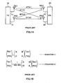
- With reference to
FIG.1A , principle of the MIMO communication will be described for a case where the number of antennas of atransmitter 10 and that of areceiver 20 are respectively two. Here, signals transmitted viaantennas 11 and 12 of thetransmitter 10 are represented as TX1 and TX2, respectively, and signals received viaantennas receiver 20 are represented as RX1 and RX2, respectively. - With this assumption, the received signals (RX1, RX2) can be expressed with (equation 1) shown in
FIG.1B . Here, A represents a propagation path characteristic between the transmitting antenna 11 and thereceiving antenna 21, B represents a propagation path characteristic between the transmittingantenna 12 and thereceiving antenna 21, C represents a propagation path characteristic between the transmitting antenna 11 and thereceiving antenna 22, and D represents a propagation path characteristic between thetransmitting antenna 12 and thereceiving antenna 22. - Thus, as for the
antenna receiver 20, the signal is received in a form of a mixed combination of TX1 and TX2, as expressed in (equation 1). In order to separate TX1 and TX2, for example, either one of TX1 and TX2 is defined as a desired signal component and the other is defined as an interference signal component, and the interference signal component should be compensated. - In order to remove (compensate) the interference signal component stated above and to obtain the transmission signal (TX1, TX2) from the received signal, an inverse matrix of a matrix consisting of these four propagation path characteristics A, B, C and D is found as expressed in (equation 2). Therefore, the
transmitter 10 transmits the signal containing a known signal for propagation path estimation (pilot signal, for example) inserted in the transmission signal, and thereceiver 20 conducts a propagation path estimation based on this known signal to obtain the propagation path characteristics A, B, C and D, thereby finding the above-described inverse matrix. - Procedures for actually finding the transmission signal (TX1, TX2) from the received signal (RX1, RX2) includes: a Zero-Forcing (ZF) arithmetic operation for separating a sub stream (respective data) by using only an inverse matrix arithmetic operation presented by (equation 2), or Minimum Mean Square Error (MMSE) arithmetic operation for separating so as to minimize an error, and the like.
- As such, in the MIMO communication, a plurality of signals, which have been transmitted at the same time at the same frequency, can be theoretically separated respectively in the receiver, and thus the communication at higher rate with higher capacity becomes possible. However, since there is an influence such as an inter-code interference due to a noise or a multipath in an actual apparatus, and/or since there is also a quantization error or the like in an actual circuitry, an interference compensation error is generated in the process of compensating for an interference signal component from the transmission signal, and there is a problem that error rate characteristic in the receiving side significantly deteriorates when this error is larger. In addition, depending on the propagation environment, a value of a determinant |AD-BC| of the inverse matrix represented in
FIG.1B (equation 2) may be closer to zero, and since the conventional apparatus attempts to compensate for the interference signal component even in such situation another problem occurs that an interference compensation error in the separated desired signal becomes greater, thereby significantly deteriorating the error rate in the receiving side. -
WO2004/021599A1 , document published on 11 March 2004 and therefore falling under Art. 54(3) EPC, discloses a spread spectrum receiver apparatus and method. The receiver has an adaptive minimum square error equalizer stage and a matched filter stage in parallel. A selector selects data from one of the two stages based upon an operating condition of the receiver. -
EP 1 233 560 - An object of the present invention is to improve an error rate characteristic in the receiving side even under the environment, in which an interference compensation error becomes larger in the receiving side, when different data are transmitted between a plurality of transmitting antennas and a plurality of receiving antennas respectively as in the MIMO communication.
- This object is solved by the invention as claimed in the independent claims. Preferred embodiments of the invention are defined by the dependent claims.
-
-
FIG.1A is a schematic diagram for describing a principle of a MIMO communication. -
FIG.1B includes equations that represent a relationship of transmission signals and received signals. -
FIG.2 is a block diagram, illustrating a configuration of a wireless receiver according to first embodiment of the present invention. -
FIG.3 is a block diagram, illustrating an internal structure of a controller section according to first embodiment of the present invention. -
FIG.4 is a flow chart, describing an operation of the controller section according to first embodiment of the present invention. -
FIG.5 is a schematic diagram for specifically describing an advantageous effect obtainable by the wireless receiver according to first embodiment of the present invention. -
FIG.6 is a block diagram, illustrating a variation of the wireless receiver according to first embodiment of the present invention. -
FIG.7 is a block diagram, illustrating a configuration of a controller section of a wireless receiver according to with second embodiment of the present invention. - Embodiments of the present invention will be described in reference to the annexed figures as follows. While the description is made in reference to a case of, for example, performing a MIMO communication by using two antennas for either of the transmitting and receiving sides, respectively, the present invention can also be applied for a case having an arbitrary number of antennas.
-
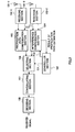
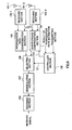
FIG.2 is a block diagram, illustrating a configuration of a wireless receiver according to a first embodiment of the present invention. - A wireless receiver shown in
FIG. 2 comprises receiving antennas 101, receiving sections 102, a propagationpath compensation section 103, aninterference compensation section 104, acontroller section 105, a selectingsection 106, ademodulating section 107 and adecoding section 108. - In
FIG.2 , a receiving section 102-1 performs a predetermined wireless receiving processing such as a down-converting and the like over a signal that is received through a receiving antenna 101-1, and then output thereof to the propagationpath compensation section 103 and theinterference compensation section 104. Similarly, a receiving section 102-2 performs a predetermined wireless receiving processing such as a down-converting and the like over a signal that is received through a receiving antenna 101-2, and then output thereof to the propagationpath compensation section 103 and theinterference compensation section 104. - The propagation
path compensation section 103 performs propagation path estimations (channel estimations) for the signals output from the receiving sections 102-1 and 102-2, and a propagation path compensation (channel variation compensation) is conducted on the basis of the results, and then the resultant signals are output to the selectingsection 106. Here, the "propagation path estimation" means estimating a magnitude of a propagation path variation (channel variation) influenced by fading or the like in a propagation path after the radio signal is transmitted from the transmitting side till arriving at the receiving antenna of the receiving side. Also, the "propagation path compensation" means, for example, complex-multiplying a predetermined vector into the original signal in order to remove (compensate) the influence of the propagation path variation based on the results of the propagation path estimation (channel estimation value). - The
interference compensation section 104 performs similar propagation path estimation for the signals output from the receiving sections 102-1, 102-2 as the propagationpath compensation section 103 performs and output this results to thecontroller section 105, and also performs the previously explained MIMO separation processing and output the separated received signals to the selectingsection 106. The selectingsection 106 selects one of the signals output from the propagationpath compensation section 103 and theinterference compensation section 104 under the control of thecontroller section 105, and output thereof to a demodulatingsection 107. The details of the control conducted by thecontroller section 105 will be discussed later. - The
demodulating section 107 performs a predetermined demodulating processing for the signal output from theselecting section 106 corresponding to a modulation system such as Quadrature Phase Shift Keying (QPSK), 16 Quadrature Amplitude Modulation (16QAM) used in the transmitting side, and output the processed signal to adecoding section 108. - The
decoding section 108 performs a predetermined decoding processing for the demodulated signal output from thedemodulating section 107 corresponding to a coding manner used in the transmitting side to obtain a received signal. -
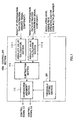
FIG.3 is a block diagram, illustrating an internal structure of thecontroller section 105. Thecontroller section 105 comprises an absolute value calculation section 111, asubtraction section 112 and acomparative judgement section 113. - The result of the propagation path estimation, which is output from the
interference compensation section 104, includes a desired signal component and an interference signal component, as mentioned above. The absolute value calculation section 111-1 calculates an absolute value of the desired signal component in the result of the propagation path estimation output from theinterference compensation section 104, and output thereof to thesubtraction section 112. Similarly, the absolute value calculation section 111-2 calculates an absolute value of the interference signal component in the result of the propagation path estimation output from theinterference compensation section 104, and output thereof to thesubtraction section 112. - The
subtraction section 112 subtracts the absolute value of the interference signal component (output of the absolute value calculation section 111-2) from the absolute value of the desired signal component (output of the absolute value calculation section 111-1), and output the obtained difference to thecomparative judgement section 113. -
Comparative judgement section 113 compares the difference output from thesubtraction section 112 with a predetermined threshold, and instructs (outputs a control signal C1 to) the selectingsection 106 to select an output of theinterference compensation section 104 when the difference is smaller than the threshold. In addition, when difference is equal to or larger than the threshold, the control signal C1 is output to the selectingsection 106 so as to select the output of the propagationpath compensation section 103. - Next, operations of the
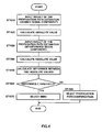
controller section 105 having the above-described configuration will be described in reference to a flow chart shown inFIG.4 . - The desired signal component of the result of the propagation path estimation output from the
interference compensation section 104 is input into the absolute value calculation section 111-1 (ST1010). The Absolute value calculation section 111-1 calculates an absolute value of the result of the propagation path estimation (ST1020). Similarly, the interference signal component of the result of the propagation path estimation output by theinterference compensation section 104 is input into the absolute value calculation section 111-2 (ST1030). The absolute value calculation section 111-2 calculates an absolute value of the result of the propagation path estimation (ST1040). - The
subtraction section 112 finds a difference between the absolute value of the desired signal component and the absolute value of the interference signal component (ST1050). Incidentally, the calculated difference indicates how relatively large the propagation path variation generated in the desired signal component is, as compared with the propagation path variation generated in the interference signal component. Thus, larger difference indicates that the propagation path variation generated in the desired signal component is larger than the propagation path variation generated in the interference signal component. -
Comparative judgement section 113 compares the difference output from thesubtraction section 112 with a predetermined threshold (ST1060), and outputs an instruction (control signal) to the selectingsection 106 to select an output of theinterference compensation section 104 when the difference is smaller than the threshold (ST1070) . In addition, when difference is equal to or larger than the threshold, the instruction (control signal) is output to the selectingsection 106 so as to select the output of the propagation path compensation section 103 (ST1080). More specifically, the operation is performed that, when the level of the propagation path variation generated in the desired signal component is equivalent to the level of the propagation path variation generated in the interference signal component, a signal, which is processed by the separation processing via a MIMO technique, is selected, and when the level of the propagation path variation generated in the interference signal component is much smaller than the level of the propagation path variation generated in the desired signal component, a signal, which is processed by a simple propagation path compensation, is selected. - While it is illustrated here that two inputs are included in the
controller section 105 in order to simplify the description, four inputs are actually included in thecontroller section 105 as described above, since the desired signal component and the interference signal component of the result of the propagation path estimation exist in respective receiving antennas. In this occasion, for example, if every two inputs corresponding to respective receiving antennas are handled via a time division, two results of the threshold determination can be obtained. In such case, in either of the determination results, the output of the propagationpath compensation section 103 may be selected only in the case where the difference calculated in thesubtraction section 112 is equal to or higher than the threshold. In addition, each of the determination results may be reflected for every receiving antenna. More specifically, the operation may be performed, in which the signal processed by the propagation path compensation processing is selected as the signal received by the receiving antenna 101-1, and the signal processed by interference compensation processing is selected as the signal received by the receiving antenna 101-2. - In addition, while the description is presented by illustrating the case of calculating the difference between the absolute values of the propagation path compensation values of the desired signal and the interference signal and comparing the difference thereof with the threshold, ratio of absolute values of propagation path estimate of the desired signal and the interference signal, respectively, that is, (absolute value of the propagation path estimate of the desired signal) / (absolute value of the propagation path estimate of the interference signal) may be calculated, and the obtained ratio may be compared with the threshold. However, a benefit of presenting smaller scale of the hardware can be provided when the procedure for utilizing the difference is selected.
- In addition, the
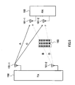
controller section 105 output the control signal C2 to theinterference compensation section 104 so as to stop the rest of the interference compensation processing except for the propagation path estimation processing, when the propagationpath compensation section 103 is selected. Having this configuration, since the electric power consumed by theinterference compensation section 104 is considerably large, an effect of cutting the power consumption can be expected. Here, it is needless to say that, when theinterference compensation section 104 is selected, a function for instructing a stop to the propagationpath compensation section 103 may be installed. Next, advantageous effects obtainable by the wireless receiver having the above-described configuration will be specifically described by usingFIG.5 . - In
FIG.5 , awireless receiver 100 according to the present embodiment receives radio signals transmitted by awireless transmission apparatus 150 having two transmitting antennas 151-1 and 151-2 via, receiving antennas 101-1 and 101-2. - However, as illustrated by the solid lines in the figure, the radio signal transmitted from the transmitting antenna 151-1 directly arrive at the receiving antenna 101-1 and 101-2, due to an absence of any obstacle in the midway of the propagation path. On the other hand, as illustrated by the dotted lines in the figure, the radio signal transmitted from the transmitting antenna 151-2 does not directly arrive, or arrives with considerably weakened signal strength, at the receiving antenna 101-1 and 101-2, due to an existence of a
building 160 in the midway of the propagation path. - In general, even if the fact that the radio signal is transmitted through multipath is considered, it can easily be supposed that the radio signal transmitted from the transmitting antenna 151-1 is received in the receiver side at stronger signal intensity than the signal intensity, at which the radio signal transmitted from the transmitting antenna 151-2 is received. In such circumstances, inMIMO communication, for example, it may often be the case that respective transmitting antennas are dedicated to respective users (respective transmission counterparts). In the embodiment shown in
FIG.5 , it may be the case, in which the signal transmitted from the transmitting antenna 151-1 is a signal for thewireless receiver 100, and the signal transmitted from the transmitting antenna 151-2 is a signal not for thewireless receiver 100. In such case, in the conventional MIMO receiver, an inverse matrix of a matrix representing the propagation path characteristic is found by additionally aiming the signal transmitted from the transmitting antenna 151-2 (or by dealing with the signals except a desired signal as an interference component), and then the interference component is removed by multiplying this inverse matrix to separate (MIMO-separation) the signals transmitted by the two transmitting antennas. - However, since the received signal strength of the signal transmitted from the transmitting antenna 151-2 is considerably low, the reliability in the arithmetic operation for inverse matrix is reduced. Consequently, the wireless receiver according to the present embodiment conducts the processing of the propagation path compensation for only the signal transmitted from the transmitting antenna 151-1 by switching the two circuits without conducting the MIMO separation processing to obtain the received signal.
- Upon trying another viewpoint, this processing correspond treating the signal transmitted from the transmitting antenna 151-2 as mere noise and not as interference component. Although the embodiment described above is presented under the considerably limited situation, as general consideration, the situation, in which the received signal strength of the interference signal component is considerably lower as relatively compared with the desired signal component, is easily caused, when the desired signal component of the signal received from the receiving antenna is compared with the interference signal component.
- The advantageous effect of the wireless receiver according to the present embodiment is exhibited under such situation.
- As described above, according to the present embodiment, when different data is respectively transmitted between a plurality of transmitting antennas and receiving antennas like MIMO communication, the receiving side select one of the propagation path compensation section and the interference compensation section, and therefore the error rate characteristics in the receiving side can be improved even in the situation where the interference compensation error is larger.
- While the method for calculating an inverse matrix has been described as the method of the interference compensation processing, the interference compensation algorithm also includes other algorithms (for example, maximum likelihood sequence estimation) and it is needless to point out that other interference compensation algorithm may also be applied thereto. Also, as shown in
FIG. 6 , switching between the propagationpath compensation section 103 and theinterference compensation section 104 may be conducted by informing thecontroller section 105 of the transmission method utilized in the transmitting side. For example, in the case where the transmitting side does not conduct the MIMO transmission and the received signal is not multiple signal since the transmission of data is conducted by only using one transmitting antenna, or in the case where the transmitting side has a plurality of transmitting antennas and the identical radio signal is transmitted from all transmitting antennas, there is a little actual profit for conducting the above-described interference compensation processing in the receiving side. Thus, by informing thecontroller section 105 of this fact (transmission method), thecontroller section 105 can transmit an indication to the selectingsection 106 so as to select the propagationpath compensation section 103. - Here, the transmitting side may inform this transmission method, or alternatively a configuration of analyzing the transmission method from the signal received in the receiving side may also be employed.
-
FIG.7 is a block diagram, illustrating a configuration of a controller section of a wireless receiver according to the second embodiment of the present invention. - Here, this
controller section 105a has a configuration similar to thecontroller section 105 shown inFIG.2 , and same numeral is referred to same element, and the description thereof is omitted. The present embodiment is characterized in that a controller section includes athreshold setting section 201. - The
threshold setting section 201 is informed of a modulation level, a coding rate, a spreading factor, or a code multiplex number used for transmission signal, and sets a threshold used in thecomparative judgement section 113 based on these values. For example, the QPSK modulation system has better error resistance as compared with 16QAM modulation system when the propagation path environment is deteriorated. When the QPSK is employed, by performing the propagation path compensation for the received signal, a probability for obtaining the data containing no error becomes higher than the case the 16QAM is employed as modulation system. More specifically, it is preferable to change the reference (threshold) for selecting one of the propagationpath compensation section 103 and theinterference compensation section 104 in response to the modulation system of the transmission signal (modulation level). Having this configuration, the case of stopping the operation of theinterference compensation section 104 by selecting the propagationpath compensation section 103 is more frequently occurred, and therefore the power consumption of the wireless receiver is reduced. - Similar discussion can be made concerning the coding rate, spreading factor or code multiplex number used for transmission signal, in addition to the modulation level. Thus, the
threshold setting section 201 sets the threshold used in thecomparative judgement section 113 by suitably changing thereof, in response to the modulation levels used for the transmission signal. - Here, the modulation levels mentioned above may be informed from the transmitting side, or obtained by analyzing the signal received from the receiver side to provide the modulation level or the like. As such, according to this embodiment, the switching reference used for the transmission signal is changed according to modulation level or the like when one of the propagation path compensation section and the interference compensation section is switched to be employed in the receiving side, and therefore the case of selecting the propagation path compensation section is more frequently occurred to provide reduced power consumption of the wireless receiver.
- The wireless receiver according to the present invention is capable of being installed in the communication terminal apparatus and the base station apparatus in the mobile radio communication system, and this can provide the communication terminal and the base station apparatus having advantageous effects similar to the above-described advantageous effects. Further, the wireless receiver according to the present invention can be utilized in the mobile radio communication system that utilizes a multi-carrier system such as Orthogonal Frequency Division Multiplex (OFDM) or the like, and this can provide the mobile radio communication system having advantageous effects similar to the above-described advantageous effects. Since the transmission system employing the multi-carrier is set to have lower symbol rate (long symbol length), there is an advantageous effect of reducing the inter-code interference by the multipath in the multipath environment.
- In addition, the inter-code interference by multipath can also be removed by inserting the guard interval.
- As have been described above, according to the present invention, the error rate characteristic in the receiving side even under the environment, in which the interference compensation error becomes larger in the receiving side, can be improved in the case of transmitting different data between a plurality of transmitting antennas and a plurality of receiving antennas respectively as in the MIMO communication.
- This specification is based on the Japanese Patent Publication No.
2004-179822, published on June 24, 2004 - The present invention can be applied to a wireless receiver, which receives data transmitted in parallel from a plurality of transmitting antenna by employing a plurality of receiving antenna, and a wireless reception method employed in such apparatus.
Claims (6)
- A MIMO, Multi-Input/Multi-Output, receiver, comprising:a receiving section (102) adapted to receive a plurality of radio signals using a plurality of receiving antennas (101);a propagation path compensation section (103) adapted to perform channel variation compensations for said plurality of radio signals to obtain the compensated signals; andan interference compensation section (104) adapted to separate the respective radio signals by a MIMO separation processing to obtain the separated signals including a desired signal component and an interference signal component,characterized In thatsaid MIMO receiver further comprises:a selection section (106) adapted to select between said compensated signals and said separated signals;an absolute value calculation section (111-1, 111-2) adapted to calculate an absolute value of the desired signal component and an absolute value of the interference signal component;a subtraction section (112) adapted to find a difference between the absolute value of the desired signal component and the absolute value of the interference signal component; anda control section (105) adapted to control said selection section (106) such that said selection section (106) selects said compensated signals in the case where the difference is equal to or larger than a threshold, and to control said selection section (106) such that said selection section (106) selects said separated signals in the case where the difference is smaller than the threshold.
- The MIMO receiver according to claim 1, further comprising
a setting section adapted to set said threshold based on a modulation level, a coding rate, a spreading factor or a code multiplex number of said radio signal - The MIMO receiver according to claim 1, wherein said radio signal is converted into a multi-carrier.
- A communication terminal apparatus comprising said MIMO receiver according to claim 1.
- A base station apparatus comprising said MIMO receiver according to claim 1.
- A MIMO (Multi-Input/Multi-Output) reception method, comprising the steps of:receiving a plurality of radio signals using a plurality of receiving antennas;performing channel variation compensations for said plurality of radio signals to obtain the compensated signals; andseparating the respective radio signals by a MIMO separation processing to obtain the separated signals including a desired signal component and an interference signal component,characterized in thatsaid MIMO reception method further comprises the steps of:calculating an absolute value of the desired signal component and an absolute value of the interference signal component;finding a difference between the absolute value of the desired signal component and the absolute value of the interference signal component;between said compensated signals and said separated signals, selecting said compensated signals in the case where the difference is equal to or larger than a threshold, and selecting said separated signals in the case where the difference is smaller than the threshold.
Applications Claiming Priority (3)
| Application Number | Priority Date | Filing Date | Title |
|---|---|---|---|
| JP2002341741 | 2002-11-26 | ||
| JP2002341741A JP3629261B2 (en) | 2002-11-26 | 2002-11-26 | Wireless receiver |
| PCT/JP2003/015059 WO2004049597A1 (en) | 2002-11-26 | 2003-11-26 | Radio reception device and radio reception method |
Publications (3)
| Publication Number | Publication Date |
|---|---|
| EP1569362A1 EP1569362A1 (en) | 2005-08-31 |
| EP1569362A4 EP1569362A4 (en) | 2005-12-28 |
| EP1569362B1 true EP1569362B1 (en) | 2011-10-26 |
Family
ID=32375864
Family Applications (1)
| Application Number | Title | Priority Date | Filing Date |
|---|---|---|---|
| EP20030775882 Expired - Fee Related EP1569362B1 (en) | 2002-11-26 | 2003-11-26 | Radio reception device and radio reception method |
Country Status (6)
| Country | Link |
|---|---|
| US (2) | US7299027B2 (en) |
| EP (1) | EP1569362B1 (en) |
| JP (1) | JP3629261B2 (en) |
| CN (1) | CN1714519B (en) |
| AU (1) | AU2003284446A1 (en) |
| WO (1) | WO2004049597A1 (en) |
Cited By (1)
| Publication number | Priority date | Publication date | Assignee | Title |
|---|---|---|---|---|
| US9374139B2 (en) | 2002-04-22 | 2016-06-21 | Ipr Licensing, Inc. | Multiple-input multiple-output radio transceiver |
Families Citing this family (26)
| Publication number | Priority date | Publication date | Assignee | Title |
|---|---|---|---|---|
| GB0222555D0 (en) * | 2002-09-28 | 2002-11-06 | Koninkl Philips Electronics Nv | Packet data transmission system |
| JP2005167873A (en) * | 2003-12-05 | 2005-06-23 | Pioneer Electronic Corp | Receiver, method of receiving, program for controlling receiving and recording medium |
| US20060034271A1 (en) * | 2004-08-16 | 2006-02-16 | Texas Instruments Incorporated | Packet detection system and method for packet-based wireless receivers having multiple receive chains |
| US20060128310A1 (en) * | 2004-12-14 | 2006-06-15 | Michael Leabman | Transmit/receive compensation in smart antenna systems |
| US7489910B2 (en) | 2005-03-30 | 2009-02-10 | Kabushiki Kaisha Toshiba | Wireless transmitter and amplifier |
| CN100557988C (en) * | 2005-07-05 | 2009-11-04 | 华为技术有限公司 | Reduce the wireless communication system of frequency repeat utilization ratio |
| US8223904B2 (en) | 2005-08-22 | 2012-07-17 | Qualcomm Incorporated | Multiple hypothesis decoding |
| KR100810231B1 (en) * | 2005-09-28 | 2008-03-06 | 삼성전자주식회사 | Method and apparatus for transmitting signal using multi antenna in a wireless communication system |
| JP4504293B2 (en) * | 2005-09-29 | 2010-07-14 | 株式会社東芝 | Wireless communication apparatus, wireless communication system, and wireless communication method provided with multiple antennas |
| WO2007058193A1 (en) * | 2005-11-16 | 2007-05-24 | Sharp Kabushiki Kaisha | Multicarrier receiver, multicarrier communication system and demodulating method |
| JP4744351B2 (en) * | 2006-04-28 | 2011-08-10 | 富士通株式会社 | Radio transmitting station and radio receiving station |
| KR101002800B1 (en) * | 2006-06-09 | 2010-12-21 | 삼성전자주식회사 | Method for transmitting common contorl information in wireless mobile communication system |
| US8098720B2 (en) * | 2006-10-06 | 2012-01-17 | Stmicroelectronics S.R.L. | Method and apparatus for suppressing adjacent channel interference and multipath propagation signals and radio receiver using said apparatus |
| CN101601200B (en) * | 2007-02-16 | 2014-07-09 | 日本电气株式会社 | Radio transmission method and interference compensation method |
| EP2219310A4 (en) | 2007-11-30 | 2014-02-19 | Nec Corp | Wireless communication system, receiver, transmitter, warless communication method, receiving method, and transmitting method |
| US8134912B2 (en) * | 2008-10-20 | 2012-03-13 | Intel Corporation | Apparatus, systems and methods adapted for opportunistic forwarding of uplink short messages in wireless metropolitan area networks |
| US8023921B2 (en) * | 2008-12-03 | 2011-09-20 | Bae Systems Information And Electronic Systems Integration Inc. | Quadratic amplitude control circuit for cosite interference cancellation |
| JP5288622B2 (en) * | 2009-06-16 | 2013-09-11 | シャープ株式会社 | Wireless communication apparatus, wireless communication system, and communication method |
| KR101667030B1 (en) * | 2009-08-10 | 2016-10-17 | 삼성전자 주식회사 | Path planning apparatus of robot and method thereof |
| US8306483B2 (en) * | 2009-12-24 | 2012-11-06 | Intel Corporation | Method and system for improving wireless link robustness using spatial diversity |
| US8888701B2 (en) * | 2011-01-27 | 2014-11-18 | Valencell, Inc. | Apparatus and methods for monitoring physiological data during environmental interference |
| JP5720058B2 (en) | 2011-04-25 | 2015-05-20 | 株式会社レイトロン | MIMO detector |
| US10284267B2 (en) | 2016-03-11 | 2019-05-07 | Huawei Technologies Canada Co., Ltd. | System and method for reducing self-interference in a wireless resource |
| US10847879B2 (en) | 2016-03-11 | 2020-11-24 | Huawei Technologies Canada Co., Ltd. | Antenna array structures for half-duplex and full-duplex multiple-input and multiple-output systems |
| JP7063751B2 (en) * | 2018-07-13 | 2022-05-09 | 日本放送協会 | Broadcast signal receiver |
| JP2022065536A (en) * | 2020-10-15 | 2022-04-27 | トヨタ自動車株式会社 | Wireless communication control method, receiving station, and program |
Family Cites Families (32)
| Publication number | Priority date | Publication date | Assignee | Title |
|---|---|---|---|---|
| US53143A (en) * | 1866-03-13 | Improvement in shaft-couplings | ||
| US5390342A (en) * | 1990-03-14 | 1995-02-14 | Pioneer Electronic Corporation | Receiver using selective diversity receiving system |
| JP2643614B2 (en) * | 1991-02-22 | 1997-08-20 | 日本電気株式会社 | Digital mobile communication terminal |
| FR2701178A1 (en) * | 1993-02-03 | 1994-08-05 | Philips Electronique Lab | Spread spectrum communication system with multiple users. |
| US5487091A (en) * | 1993-08-13 | 1996-01-23 | Motorola, Inc. | Method for determining signal usability in a diversity receiver |
| US5440590A (en) * | 1993-11-01 | 1995-08-08 | Motorola, Inc. | Method and apparatus for producing a usable signal from received diverse modulated signals |
| US5553102A (en) * | 1994-12-01 | 1996-09-03 | Motorola, Inc. | Diversity reception communication system with maximum ratio combining method |
| US5940452A (en) * | 1995-11-29 | 1999-08-17 | Motorola, Inc. | Dual mode radio subscriber unit having a diversity receiver apparatus and method therefor |
| JP3795984B2 (en) * | 1996-12-20 | 2006-07-12 | 富士通株式会社 | Wireless receiver |
| DE19743123B4 (en) * | 1997-09-30 | 2005-11-24 | Harman Becker Automotive Systems (Xsys Division) Gmbh | Method and circuit arrangement for selecting one of several receivers of a diversity receiving system |
| JPH11289211A (en) | 1998-03-31 | 1999-10-19 | Toyota Central Res & Dev Lab Inc | Adaptive receiver |
| US6181754B1 (en) * | 1998-06-12 | 2001-01-30 | Cadence Design Systems, Inc. | System and method for modeling mixed signal RF circuits in a digital signal environment |
| US6154485A (en) * | 1998-10-19 | 2000-11-28 | Motorola, Inc. | Receiver in a wireless communications system for receiving signals having combined orthogonal transmit diversity and adaptive array techniques |
| JP2000224139A (en) * | 1999-02-01 | 2000-08-11 | Sony Corp | Diversity receiver |
| JP3678944B2 (en) * | 1999-07-02 | 2005-08-03 | 松下電器産業株式会社 | Wireless communication apparatus and wireless communication method |
| US6377636B1 (en) * | 1999-11-02 | 2002-04-23 | Iospan Wirless, Inc. | Method and wireless communications system using coordinated transmission and training for interference mitigation |
| US7068628B2 (en) | 2000-05-22 | 2006-06-27 | At&T Corp. | MIMO OFDM system |
| JP2001358624A (en) * | 2000-06-14 | 2001-12-26 | Sony Corp | Receiver |
| JP3699883B2 (en) * | 2000-06-29 | 2005-09-28 | 松下電器産業株式会社 | Radio base station apparatus and radio communication method |
| JP3421314B2 (en) | 2000-10-04 | 2003-06-30 | 松下電器産業株式会社 | Path selection device and path selection method |
| KR100510434B1 (en) * | 2001-04-09 | 2005-08-26 | 니폰덴신뎅와 가부시키가이샤 | OFDM signal transmission system, OFDM signal transmission apparatus and OFDM signal receiver |
| US6751187B2 (en) * | 2001-05-17 | 2004-06-15 | Qualcomm Incorporated | Method and apparatus for processing data for transmission in a multi-channel communication system using selective channel transmission |
| US20020193146A1 (en) * | 2001-06-06 | 2002-12-19 | Mark Wallace | Method and apparatus for antenna diversity in a wireless communication system |
| US20030048753A1 (en) * | 2001-08-30 | 2003-03-13 | Ahmad Jalali | Method and apparatus for multi-path elimination in a wireless communication system |
| CA2415170C (en) * | 2001-12-28 | 2008-07-15 | Ntt Docomo, Inc. | Receiver, transmitter, communication system, and method of communication |
| US7224704B2 (en) * | 2002-04-01 | 2007-05-29 | Texas Instruments Incorporated | Wireless network scheduling data frames including physical layer configuration |
| US7463577B2 (en) * | 2002-04-09 | 2008-12-09 | Panasonic Corporation | OFDM communication method and OFDM communication device |
| US6904081B2 (en) | 2002-08-30 | 2005-06-07 | Motorola, Inc. | Spread spectrum receiver apparatus and method |
| JP4444779B2 (en) * | 2004-10-12 | 2010-03-31 | リンナイ株式会社 | Remote control device |
| US7224269B2 (en) * | 2004-12-15 | 2007-05-29 | Ford Global Technologies, Llc | Method and system for resetting tire pressure monitoring system for an automotive vehicle |
| CN101112017B (en) * | 2005-02-03 | 2011-06-01 | 富士通株式会社 | Radio communication system and its method |
| US7558223B2 (en) * | 2005-04-04 | 2009-07-07 | Panasonic Corporation | OFDM receiving method of OFDM receiver for receiving an OFDM signal via a plurality of space paths |
-
2002
- 2002-11-26 JP JP2002341741A patent/JP3629261B2/en not_active Expired - Fee Related
-
2003
- 2003-11-26 US US10/536,010 patent/US7299027B2/en not_active Expired - Lifetime
- 2003-11-26 CN CN2003801038379A patent/CN1714519B/en not_active Expired - Fee Related
- 2003-11-26 AU AU2003284446A patent/AU2003284446A1/en not_active Abandoned
- 2003-11-26 EP EP20030775882 patent/EP1569362B1/en not_active Expired - Fee Related
- 2003-11-26 WO PCT/JP2003/015059 patent/WO2004049597A1/en active Application Filing
-
2007
- 2007-09-21 US US11/859,550 patent/US20080020802A1/en not_active Abandoned
Cited By (1)
| Publication number | Priority date | Publication date | Assignee | Title |
|---|---|---|---|---|
| US9374139B2 (en) | 2002-04-22 | 2016-06-21 | Ipr Licensing, Inc. | Multiple-input multiple-output radio transceiver |
Also Published As
| Publication number | Publication date |
|---|---|
| US20060063491A1 (en) | 2006-03-23 |
| EP1569362A4 (en) | 2005-12-28 |
| EP1569362A1 (en) | 2005-08-31 |
| US20080020802A1 (en) | 2008-01-24 |
| WO2004049597A1 (en) | 2004-06-10 |
| AU2003284446A1 (en) | 2004-06-18 |
| JP3629261B2 (en) | 2005-03-16 |
| US7299027B2 (en) | 2007-11-20 |
| CN1714519B (en) | 2011-05-04 |
| CN1714519A (en) | 2005-12-28 |
| JP2004179822A (en) | 2004-06-24 |
Similar Documents
| Publication | Publication Date | Title |
|---|---|---|
| EP1569362B1 (en) | Radio reception device and radio reception method | |
| KR100737773B1 (en) | Channel estimation device, channel estimation method and wireless receiver | |
| EP1494381B1 (en) | Ofdm communication method and ofdm communication device | |
| EP1798874B1 (en) | Mobile station device and communication partner selection method | |
| US7796680B2 (en) | Mobile communication system and wireless apparatus to be used for the same | |
| EP1845634B1 (en) | Method and system for diversity processing including using dedicated pilot method for closed loop | |
| EP1850508A2 (en) | Wireless transmitting station and wireless receiving station | |
| EP1860789A1 (en) | Communication device and communication method | |
| EP1505758A1 (en) | Method and apparatus for determining a shuffling pattern based on a minimum signal to noise ratio in a double space-time transmit diversity system | |
| EP1759470A1 (en) | Apparatus and method for beamforming in a multi-antenna system | |
| JPWO2006075732A1 (en) | Wireless communication device | |
| KR20020026605A (en) | Radio base station unit and radio communication method | |
| KR101003373B1 (en) | Apparatus and method for interference cancellation in multiple antenna telecommunication system | |
| EP1838020A1 (en) | Frequency division communication system | |
| US8942325B2 (en) | Wireless communication apparatus and communication method | |
| WO2008129427A2 (en) | Method for transmitting and estimating symbols coded with a coding matrix, and corresponding receiver and transmitter | |
| JP5340344B2 (en) | Communication apparatus and communication method | |
| EP2654257B1 (en) | Method and apparatus for blind detection of secondary pilot signal in a wireless communication system | |
| JP4776292B2 (en) | Communication apparatus and communication method | |
| KR100577541B1 (en) | Apparatus and method for detecting traffic cahannel signal in rake reciever | |
| JP5369545B2 (en) | Demodulator and demodulation method | |
| EP1700439B1 (en) | Universal derotator for umts modes | |
| JP2006173764A (en) | Multicarrier signal demodulation circuit and multicarrier signal demodulation method | |
| WO2006100767A1 (en) | Wireless communication system | |
| JP4217705B2 (en) | Receiver |
Legal Events
| Date | Code | Title | Description |
|---|---|---|---|
| PUAI | Public reference made under article 153(3) epc to a published international application that has entered the european phase |
Free format text: ORIGINAL CODE: 0009012 |
|
| 17P | Request for examination filed |
Effective date: 20050617 |
|
| AK | Designated contracting states |
Kind code of ref document: A1 Designated state(s): AT BE BG CH CY CZ DE DK EE ES FI FR GB GR HU IE IT LI LU MC NL PT RO SE SI SK TR |
|
| AX | Request for extension of the european patent |
Extension state: AL LT LV MK |
|
| A4 | Supplementary search report drawn up and despatched |
Effective date: 20051110 |
|
| RIC1 | Information provided on ipc code assigned before grant |
Ipc: 7H 04B 7/08 A |
|
| DAX | Request for extension of the european patent (deleted) | ||
| RBV | Designated contracting states (corrected) |
Designated state(s): DE FR GB |
|
| RAP1 | Party data changed (applicant data changed or rights of an application transferred) |
Owner name: PANASONIC CORPORATION |
|
| GRAP | Despatch of communication of intention to grant a patent |
Free format text: ORIGINAL CODE: EPIDOSNIGR1 |
|
| GRAS | Grant fee paid |
Free format text: ORIGINAL CODE: EPIDOSNIGR3 |
|
| GRAA | (expected) grant |
Free format text: ORIGINAL CODE: 0009210 |
|
| AK | Designated contracting states |
Kind code of ref document: B1 Designated state(s): DE FR GB |
|
| REG | Reference to a national code |
Ref country code: GB Ref legal event code: FG4D |
|
| REG | Reference to a national code |
Ref country code: DE Ref legal event code: R096 Ref document number: 60338926 Country of ref document: DE Effective date: 20120119 |
|
| PLBE | No opposition filed within time limit |
Free format text: ORIGINAL CODE: 0009261 |
|
| STAA | Information on the status of an ep patent application or granted ep patent |
Free format text: STATUS: NO OPPOSITION FILED WITHIN TIME LIMIT |
|
| 26N | No opposition filed |
Effective date: 20120727 |
|
| REG | Reference to a national code |
Ref country code: DE Ref legal event code: R097 Ref document number: 60338926 Country of ref document: DE Effective date: 20120727 |
|
| REG | Reference to a national code |
Ref country code: GB Ref legal event code: 732E Free format text: REGISTERED BETWEEN 20140925 AND 20141001 |
|
| REG | Reference to a national code |
Ref country code: DE Ref legal event code: R082 Ref document number: 60338926 Country of ref document: DE Representative=s name: EISENFUEHR SPEISER PATENTANWAELTE RECHTSANWAEL, DE |
|
| REG | Reference to a national code |
Ref country code: DE Ref legal event code: R081 Ref document number: 60338926 Country of ref document: DE Owner name: INVENTERGY, INC. (N.D.GES.D. STAATES DELAWARE), US Free format text: FORMER OWNER: MATSUSHITA ELECTRIC INDUSTRIAL CO., LTD., KADOMA-SHI, OSAKA, JP Effective date: 20111124 Ref country code: DE Ref legal event code: R082 Ref document number: 60338926 Country of ref document: DE Representative=s name: EISENFUEHR SPEISER PATENTANWAELTE RECHTSANWAEL, DE Effective date: 20150109 Ref country code: DE Ref legal event code: R081 Ref document number: 60338926 Country of ref document: DE Owner name: INVENTERGY, INC. (N.D.GES.D. STAATES DELAWARE), US Free format text: FORMER OWNER: PANASONIC CORPORATION, KADOMA, OSAKA, JP Effective date: 20150109 Ref country code: DE Ref legal event code: R081 Ref document number: 60338926 Country of ref document: DE Owner name: INVT SPE LLC (N.D.GES.D. STAATES DELAWARE), SA, US Free format text: FORMER OWNER: MATSUSHITA ELECTRIC INDUSTRIAL CO., LTD., KADOMA-SHI, OSAKA, JP Effective date: 20111124 Ref country code: DE Ref legal event code: R081 Ref document number: 60338926 Country of ref document: DE Owner name: INVT SPE LLC (N.D.GES.D. STAATES DELAWARE), SA, US Free format text: FORMER OWNER: PANASONIC CORPORATION, KADOMA, OSAKA, JP Effective date: 20150109 |
|
| REG | Reference to a national code |
Ref country code: GB Ref legal event code: 732E Free format text: REGISTERED BETWEEN 20150129 AND 20150204 |
|
| REG | Reference to a national code |
Ref country code: FR Ref legal event code: PLFP Year of fee payment: 13 |
|
| REG | Reference to a national code |
Ref country code: FR Ref legal event code: TP Owner name: INVENTERGY, INC., US Effective date: 20151027 |
|
| REG | Reference to a national code |
Ref country code: FR Ref legal event code: PLFP Year of fee payment: 14 |
|
| REG | Reference to a national code |
Ref country code: DE Ref legal event code: R082 Ref document number: 60338926 Country of ref document: DE Representative=s name: EISENFUEHR SPEISER PATENTANWAELTE RECHTSANWAEL, DE Ref country code: DE Ref legal event code: R081 Ref document number: 60338926 Country of ref document: DE Owner name: INVT SPE LLC (N.D.GES.D. STAATES DELAWARE), SA, US Free format text: FORMER OWNER: INVENTERGY, INC. (N.D.GES.D. STAATES DELAWARE), CAMPBELL, CALIF., US |
|
| REG | Reference to a national code |
Ref country code: FR Ref legal event code: PLFP Year of fee payment: 15 |
|
| REG | Reference to a national code |
Ref country code: GB Ref legal event code: 732E Free format text: REGISTERED BETWEEN 20171214 AND 20171222 |
|
| PGFP | Annual fee paid to national office [announced via postgrant information from national office to epo] |
Ref country code: FR Payment date: 20171012 Year of fee payment: 15 Ref country code: DE Payment date: 20171121 Year of fee payment: 15 |
|
| PGFP | Annual fee paid to national office [announced via postgrant information from national office to epo] |
Ref country code: GB Payment date: 20171122 Year of fee payment: 15 |
|
| REG | Reference to a national code |
Ref country code: FR Ref legal event code: TP Owner name: INVT SPE LLC, US Effective date: 20171018 |
|
| REG | Reference to a national code |
Ref country code: DE Ref legal event code: R119 Ref document number: 60338926 Country of ref document: DE |
|
| GBPC | Gb: european patent ceased through non-payment of renewal fee |
Effective date: 20181126 |
|
| PG25 | Lapsed in a contracting state [announced via postgrant information from national office to epo] |
Ref country code: DE Free format text: LAPSE BECAUSE OF NON-PAYMENT OF DUE FEES Effective date: 20190601 Ref country code: FR Free format text: LAPSE BECAUSE OF NON-PAYMENT OF DUE FEES Effective date: 20181130 |
|
| PG25 | Lapsed in a contracting state [announced via postgrant information from national office to epo] |
Ref country code: GB Free format text: LAPSE BECAUSE OF NON-PAYMENT OF DUE FEES Effective date: 20181126 |