EP1568629B1 - Procédé et dispositif pour former une pile de paquets - Google Patents
Procédé et dispositif pour former une pile de paquets Download PDFInfo
- Publication number
- EP1568629B1 EP1568629B1 EP05101234A EP05101234A EP1568629B1 EP 1568629 B1 EP1568629 B1 EP 1568629B1 EP 05101234 A EP05101234 A EP 05101234A EP 05101234 A EP05101234 A EP 05101234A EP 1568629 B1 EP1568629 B1 EP 1568629B1
- Authority
- EP
- European Patent Office
- Prior art keywords
- channel
- axis
- conveyor
- output
- conveyor channel
- Prior art date
- Legal status (The legal status is an assumption and is not a legal conclusion. Google has not performed a legal analysis and makes no representation as to the accuracy of the status listed.)
- Expired - Lifetime
Links
- 238000000034 method Methods 0.000 title claims abstract description 20
- 230000005540 biological transmission Effects 0.000 claims description 3
- 230000002452 interceptive effect Effects 0.000 description 2
- 238000005192 partition Methods 0.000 description 2
- 230000015572 biosynthetic process Effects 0.000 description 1
- 235000019504 cigarettes Nutrition 0.000 description 1
- 238000010586 diagram Methods 0.000 description 1
Images



Classifications
-
- B—PERFORMING OPERATIONS; TRANSPORTING
- B65—CONVEYING; PACKING; STORING; HANDLING THIN OR FILAMENTARY MATERIAL
- B65G—TRANSPORT OR STORAGE DEVICES, e.g. CONVEYORS FOR LOADING OR TIPPING, SHOP CONVEYOR SYSTEMS OR PNEUMATIC TUBE CONVEYORS
- B65G57/00—Stacking of articles
- B65G57/32—Stacking of articles characterised by stacking during transit
-
- B—PERFORMING OPERATIONS; TRANSPORTING
- B65—CONVEYING; PACKING; STORING; HANDLING THIN OR FILAMENTARY MATERIAL
- B65G—TRANSPORT OR STORAGE DEVICES, e.g. CONVEYORS FOR LOADING OR TIPPING, SHOP CONVEYOR SYSTEMS OR PNEUMATIC TUBE CONVEYORS
- B65G33/00—Screw or rotary spiral conveyors
- B65G33/02—Screw or rotary spiral conveyors for articles
- B65G33/04—Screw or rotary spiral conveyors for articles conveyed between a single screw and guiding means
-
- B—PERFORMING OPERATIONS; TRANSPORTING
- B65—CONVEYING; PACKING; STORING; HANDLING THIN OR FILAMENTARY MATERIAL
- B65G—TRANSPORT OR STORAGE DEVICES, e.g. CONVEYORS FOR LOADING OR TIPPING, SHOP CONVEYOR SYSTEMS OR PNEUMATIC TUBE CONVEYORS
- B65G47/00—Article or material-handling devices associated with conveyors; Methods employing such devices
- B65G47/74—Feeding, transfer, or discharging devices of particular kinds or types
- B65G47/82—Rotary or reciprocating members for direct action on articles or materials, e.g. pushers, rakes, shovels
-
- B—PERFORMING OPERATIONS; TRANSPORTING
- B65—CONVEYING; PACKING; STORING; HANDLING THIN OR FILAMENTARY MATERIAL
- B65G—TRANSPORT OR STORAGE DEVICES, e.g. CONVEYORS FOR LOADING OR TIPPING, SHOP CONVEYOR SYSTEMS OR PNEUMATIC TUBE CONVEYORS
- B65G2201/00—Indexing codes relating to handling devices, e.g. conveyors, characterised by the type of product or load being conveyed or handled
- B65G2201/02—Articles
- B65G2201/0226—Cigarettes
-
- B—PERFORMING OPERATIONS; TRANSPORTING
- B65—CONVEYING; PACKING; STORING; HANDLING THIN OR FILAMENTARY MATERIAL
- B65G—TRANSPORT OR STORAGE DEVICES, e.g. CONVEYORS FOR LOADING OR TIPPING, SHOP CONVEYOR SYSTEMS OR PNEUMATIC TUBE CONVEYORS
- B65G2201/00—Indexing codes relating to handling devices, e.g. conveyors, characterised by the type of product or load being conveyed or handled
- B65G2201/02—Articles
- B65G2201/0235—Containers
- B65G2201/025—Boxes
Definitions
- the present invention relates to a method and device for forming a stack of packets.
- the present invention relates to a method and device for forming a stack of packets, whereby the packets to be stacked are fed successively in a first direction to an input of a conveyor channel comprising said input and an output, and extending in a second direction substantially crosswise to the first direction, and are stacked by transferring the packets along the conveyor channel in the second direction to said output by means of a screw push device comprising an n-start screw mounted to rotate about an axis substantially crosswise to the first direction, and in turn comprising a core coaxial with said axis, and n helical channels, each for receiving a relative packet and extending about the core and through the conveyor channel; the stack being transferred at said output to an output conveyor by means of extracting means independent of the screw push device; and the output conveyor extending from the output of the conveyor channel in a third direction crosswise to the axis of the screw.
- the formed stack is removed from the screw push device using an output conveyor tangent to the core of the screw push device; and the stack, formed as described above, is transferred from the screw push device to the output conveyor by extracting means comprising pushers moving back and forth through the conveyor channel and aligned with the output conveyor.
- EP 0814038 A1 discloses such a method and device, which are conform to the preambles of claim 1 and claim 10.
- the above method involves several drawbacks, on account of the pushers having to perform a forward and return movement through the conveyor channel without interfering with the packets in the next stack moving up along the conveyor channel.
- the output conveyor is always positioned tangent to the core of the screw push device, thus invariably resulting in a relatively bulky structure.
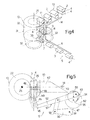
- Number 1 in Figure 1 indicates as a whole a device for forming a stack 2 of n packets 3 of cigarettes (in the example shown, n equals two, but may be more than two), each of which has a longitudinal axis 4, and a cross section which, in the example shown, is substantially oval, but which may be any shape, e.g. rectangular with or without bevelled and/or rounded edges.
- Device 1 comprises a feed conveyor 5 for successively feeding packets 3 axially, i.e. parallel to their longitudinal axes 4, and in a substantially horizontal feed direction 6 to an input 7 of a conveyor channel 8 ( Figure 3) extending in a conveying direction 9 ( Figure 3) which, in the example shown, is a substantially vertical direction crosswise to feed direction 6.
- Device 1 also comprises a push device 10 for feeding packets 3, crosswise to their longitudinal axes 4, along conveyor channel 8 and in conveying direction 9 from input 7 to an output 11, while forming, along conveyor channel 8, a succession of stacks 2, each of which is transferred, crosswise to longitudinal axes 4 of relative packets 3 and by means of an extracting device 12, from output 11 to an output conveyor 13 located at a different level - higher up, in the example shown - with respect to feed conveyor 5, and which feeds stacks 2 in an output direction 14 which, in the example shown, is crosswise to feed direction 6.
- Feed conveyor 5 comprises two belts 15 and 16, which are looped about respective pairs of pulleys 17 rotating about respective axes 18 crosswise to feed direction 6, and have respective conveying branches 19 facing each other and movable in feed direction 6 to define a channel 20 extending along an axis 21 parallel to feed direction 6, and for receiving a succession of packets 3 positioned with their longitudinal axes 4 coaxial with axis 21.
- Push device 10 comprises a tubular, n-start screw 22, which is fitted to a drive shaft 23 in turn fitted to a frame 24 and having an axis 25 (in the example shown, a vertical axis 25) substantially crosswise to feed direction 6.
- Screw 22 comprises a core 26 coaxial with drive shaft 23; and n variable-pitch, helical channels 27, each of which is of a height approximately equal to but no less than the thickness of a packet 3, and of a depth at most equal to the width of a packet 3, so that, when a packet 3 is positioned inside a respective helical channel 27, with respective longitudinal axis 4 tangent to an axis of helical channel 27, a portion of each axial end of packet 3 projects at all times outwards of helical channel 27.
- Each helical channel 27 comprises an input portion 28a and an output portion 28b extending in respective planes substantially perpendicular to axis 25.
- Input portion 28a is on a level with feed conveyor 5, and has an axis tangent to axis 21 of channel 20, and output portion 28b is on a level with output conveyor 13, so that the pitch of each helical channel 27 varies between a value of substantially zero at portions 28a and 28b, and a maximum value at an intermediate portion of helical channel 27.
- Push device 10 also comprises a fixed retaining bar 29 substantially tangent to the periphery of screw 22 and extending the full length of screw 22 in conveying direction 9; at least a portion of retaining bar 29 extending outside input portions 28a of helical channels 27 is positioned facing the output of channel 20; and retaining bar 29 is supported at the ends by respective fixed brackets 30, and cooperates with the leading end of each packet 3 fed to screw 22 to define a side of conveyor channel 8.
- core 26 of screw 22 is of constant diameter
- screw 22 itself comprises a substantially cylindrical top portion 31, and a downward-tapering, truncated-cone-shaped bottom portion 32, so that each helical channel 27 comprises an output portion extending along top portion 31 and of constant depth substantially equal to the width of each packet 3, and an input portion extending along bottom portion 32 and varying in depth between a maximum substantially equal to the width of a packet 3, and a minimum, at input 7, substantially equal to half the width of a packet 3.
- screw 22 cooperates with a further n-start screw 33 which rotates about a respective axis 34, parallel to axis 25, at the same angular speed as but in the opposite direction to screw 22.
- Screw 33 is truncated-cone-shaped, tapering upwards, is of substantially the same length as bottom portion 32 of screw 22, and is tangent to bottom portion 32. More specifically, axes 34 and 25 define a plane perpendicular to axis 21, and screw 33 comprises n helical channels 35 varying in pitch in the same way as helical channels 27 along bottom portion 32 of screw 22.
- Each helical channel 35 rotates in time with a respective helical channel 27 to define, along input portion 28a of respective helical channel 27, a seat 36 which is bounded by retaining bar 29 on the opposite side to that facing channel 20, has a cross section of substantially the same shape and approximately the same size as, but no smaller than, that of packets 3, and, as screws 22 and 33 rotate, moves up along conveyor channel 8 from a bottom start position in which seat 36 is coaxial with axis 21 and coincides with input 7.
- screw 22 in the example shown i.e. having a tapering bottom portion 32 cooperating with a screw 33, is used solely to better stabilize the oval-section packets 3 entering conveyor channel 8, and that, in examples not shown, screw 22 is cylindrical, and screw 33 is either eliminated or, depending on the depth of helical channels 27, is maintained and of a length slightly less than that of screw 22.
- Output conveyor 13 extends in output direction 14 from output 11 of conveyor channel 8, and comprises two belts 37 and 38 looped about respective pairs of pulleys 39 (only one of each pair shown) rotating about respective axes 40 crosswise to output direction 14.
- Belts 37 and 38 have respective conveying branches 41 moving in output direction 14 and facing each other with the interposition of a fixed partition 42, which has an axis 43 parallel to output direction 14 and perpendicular to axis 25, and defines, together with conveying branches 41, two channels 44, each for receiving a respective succession of packets 3, which are each positioned with respective longitudinal axis 4 crosswise to axis 43, and are each aligned vertically with a respective packet 3 in the other channel 44 to form a respective stack 2.
- channels 44 are two in number because the example shown relates to the formation of stacks 2 defined by respective pairs of superimposed packets 3. To form stacks 2 of n packets, where n>2, both helical channels 27 and channels 44 are of n in number.
- each packet 3 of each stack 2 is transferred from conveyor channel 8 to a respective channel 44 by means of extracting device 12, which comprises a comb 45 with n teeth 46 (in the example shown, two teeth 46), and an actuating device 47 for moving comb 45 along an annular path 48 comprising a work portion 49, which is substantially parallel to axis 43 and extends radially with respect to axis 25 and through conveyor channel 8 towards the inputs of channels 44, and a substantially U-shaped return portion 50 comprising an end branch connected to the inner end of work portion 49 and substantially tangent to core 26 in a direction crosswise to axis 43.
- extracting device 12 comprises a comb 45 with n teeth 46 (in the example shown, two teeth 46), and an actuating device 47 for moving comb 45 along an annular path 48 comprising a work portion 49, which is substantially parallel to axis 43 and extends radially with respect to axis 25 and through conveyor channel 8 towards the inputs of channels 44, and a substantially U-shaped return portion 50 comprising an
- each tooth 46 is positioned substantially crosswise to axis 43 and facing the input of respective channel 44, and engages a relative groove 51 formed in core 26 and extending along part of output portion 28b of respective helical channel 27.
- Actuating device 47 comprises a rod 52 fitted integrally at one end with comb 45, and hinged at the other end, by means of an eccentric pin 53, to a drum 54 powered to rotate, clockwise in Figure 5 and on a support 55, about a respective axis 56 parallel to pin 53 and to axis 25.
- Rod 52 and drum 54 respectively define a connecting rod and crank of an articulated quadrilateral transmission 57, which also comprises a further crank 58 hinged at one end to an intermediate portion of rod 52, and at the other end to a pin 59 parallel to axis 25 and fitted to one end of a lever 60 powered by a known cam device (not shown) to oscillate about an axis 61 parallel to axis 25.
- axis 56 and support 55 are therefore fixed.
- support 55 is defined by a powered drum rotating about a respective axis 62 parallel to and a given distance from axis 56.
- each packet 3 fed by feed conveyor 5 to push device 10 reaches input 7 in time with a relative seat 36, engages seat 36 and is arrested against retaining bar 29, and is moved, together with relative seat 36 and crosswise to its longitudinal axis 4, along conveyor channel 8 to output 11.
- each packet 3 is superimposed on all the other packets 3 occupying conveyor channel 8 at the same time.
Landscapes
- Engineering & Computer Science (AREA)
- Mechanical Engineering (AREA)
- Attitude Control For Articles On Conveyors (AREA)
- Pile Receivers (AREA)
- Data Exchanges In Wide-Area Networks (AREA)
- Making Paper Articles (AREA)
Claims (24)
- Procédé de formation d'une pile de n paquets, le procédé comprenant les étapes d'alimentation des paquets individuels (3) de ladite pile (2) dans le sens axial et en succession dans une première direction 6) vers un canal de convoyeur (8) comprenant une entrée (7) et une sortie (11) et s'étendant dans une seconde direction (9) essentiellement transversale à ladite première direction (6), lesdits paquets (3) étant alimentés dans le sens axial et de manière successive vers ladite entrée (7) ; d'empilage desdits paquets (3) par transfert des paquets (3) dans le sens transversal le long dudit canal de convoyeur (8) dans la seconde direction (9) vers ladite sortie (11) au moyen d'un dispositif de poussée à vis (10) comprenant une vis (22) ayant n démarrages et montée de manière à tourner autour d'un premier axe (25) essentiellement transversal ladite première direction (6), et à son tour comprenant un noyau (26) coaxial audit premier axe (25), et n canaux hélicoïdaux (27), chacun desdits canaux hélicoïdaux (27) ayant un démarrage respectif, qui reçoit un dit paquet relatif (3) et qui s'étend autour dudit noyau (26) et au travers dudit canal de convoyeur (8) ; et de transfert de ladite pile (2), vers ladite sortie (11), sur un convoyeur de sortie (13) au moyen de moyens d'extraction (12) indépendants dudit dispositif de poussée à vis (10) ; le convoyeur de sortie (13) s'étendant transversalement dans une troisième direction (14) entre ladite sortie (11) et le premier axe ((25) ; et le procédé est caractérisé en ce que les paquets (3) disposés dans ladite pile (2) sont transférés transversalement jusqu' audit convoyeur de sortie (13), qui a un second axe (43) perpendiculaire audit premier axe (25) ; ladite troisième direction (14) est une direction radiale par rapport au premier axe (25), et lesdits moyens d'extraction (12) se déplacent le long d'un chemin annulaire (48) comprenant une partie de travail (49) et une partie de retour (50) ; ladite partie de travail (49) s'étendant essentiellement dans ladite troisième direction (14), au travers dudit canal de convoyeur (8) et de tous lesdits canaux hélicoïdaux (27), entre une première position tangente audit noyau (26) et une seconde position située à l'extérieur dudit dispositif de poussée à vis (10) et dudit canal de convoyeur (8).
- Procédé selon la revendication 1, dans lequel ladite partie de retour (50) comprend une partie d'extrémité destinée à amener lesdits moyens d'extraction (12) dans ladite première position ; ladite partie d'extrémité étant essentiellement transversale à ladite troisième direction (14) et tangente audit noyau (26).
- Procédé selon la revendication 1 ou la revendication 2, dans lequel lesdits moyens d'extraction (12) comprennent un peigne (45) qui, dans ladite première position, est essentiellement tangent audit noyau (26) et transversal à ladite troisième direction (14) ; ledit peigne (45) comprenant n dents (46), chacune desquelles, dans ladite première position, est disposée sur un dit canal hélicoïdal respectif (27) et dans le sens radial à l'intérieur dudit canal de convoyeur (8), et se déplace, le long de ladite partie de travail (49), essentiellement dans la troisième direction (14) au travers dudit canal hélicoïdal relatif (27) et dudit canal de convoyeur (8).
- Procédé selon l'une quelconque des revendications 1 à 3, dans lequel ledit canal de convoyeur (8) est défini par un élément de retenue (29) tangent au dispositif de poussée à vis (10) et qui s'étend dans une direction parallèle à ladite seconde direction (9).
- Procédé selon l'une quelconque des revendications 1 à 4, dans lequel lesdits paquets (3) sont alimentés dans ladite seconde direction (9) et au moins le long d'une partie initiale dudit canal de convoyeur (8) au moyen dudit dispositif de poussée à vis (10) et au moyen d'un autre dispositif de poussée à vis (33) ayant un nombre n de canaux hélicoïdaux respectifs (35), chacun d'entre eux correspondant à un canal hélicoïdal respectif (27) de l'autre dispositif de poussée à vis (10) ; lesdits deux dispositifs de poussée à vis (10, 33) étant tangents l'un par rapport à l'autre le long dudit canal de convoyeur (8), et étant montés de manière à tourner dans des directions opposées autour d'axes parallèles respectifs (25, 34).
- Procédé selon la revendication 5, dans lequel chacun desdits canaux hélicoïdaux (27) et des canaux hélicoïdaux en correspondance relative (35) coopèrent mutuellement sur ledit canal de convoyeur (8) afin de définir, entre eux et à l'intérieur dudit canal de convoyeur (8), un siège de logement (36) d'un dit paquet respectif (3).
- Procédé selon la revendication 6, dans lequel ledit siège (36) a une section essentiellement ovale destinée à loger un dit paquet respectif de section ovale (3).
- Procédé selon l'une quelconque des revendications 1 à 7, dans lequel ladite première direction (6) et ladite troisième direction (14) sont transversale l'une par rapport à l'autre.
- Procédé selon l'une quelconque des revendications 1 à 8, dans lequel les paquets (3) sont alimentés de manière continue à l'entrée (7) dudit canal de convoyeur (8).
- Dispositif de formation d'une pile de n paquets, le dispositif (1) comprenant un canal de convoyeur (8) comprenant une entrée (7) et une sortie (11) ; des moyens d'alimentation (5) destinés à alimenter lesdits paquets (3) de manière successive vers ladite entrée (7) dans une première direction (6), le canal de convoyeur (8) s'étendant dans une seconde direction (9) essentiellement transversale à ladite première direction (6) ; un dispositif de poussée à vis (10) destiné à déplacer lesdits paquets (3) le long dudit canal de convoyeur (8) vers ladite sortie (11), et comprenant à son tour une vis pour n démarrages (22), qui comprend un premier axe (25) essentiellement transversal à ladite première direction (6), qui tourne autour dudit premier axe (25), et qui comprend un noyau (26) coaxial audit premier axe (25), et n canaux hélicoïdaux (27), chacun d'entre eux s'étendant autour dudit noyau (26) et au travers dudit canal de convoyeur (8) ; un convoyeur de sortie (13) qui s'étend à partir de ladite sortie (11) dans la troisième direction (14) de manière transversale audit premier axe (25) ; et des moyens d'extraction (12) indépendants dudit dispositif de poussée à vis (10) et destinés à transférer ladite pile (2) sur le convoyeur de sortie (13) vers ladite sortie (11) ; le dispositif (1) étant caractérisé en ce que ledit convoyeur de sortie (13) a un second axe (43) qui est perpendiculaire audit premier axe (25) ; ladite troisième direction (14) est dirigée dans le sens radial par rapport au premier axe (25), et lesdits moyens d'extraction (12) sont mobiles le long d'un chemin annulaire (48) qui comprend une partie de travail (49) et une partie de retour (50) ; ladite partie de travail (49) s'étendant dans ladite troisième direction (14), au travers dudit canal de convoyeur (8) et de tous lesdits canaux hélicoïdaux (27), entre une première position tangente audit noyau (26) et une seconde position située à l'extérieur dudit dispositif de poussée à vis (10) et dudit canal de convoyeur (8).
- Dispositif selon la revendication 10, dans lequel ladite partie de retour (50) comprend une partie d'extrémité destinée à amener lesdits moyens d'extraction (12) dans ladite première position ; ladite partie d'extrémité étant essentiellement transversale à ladite troisième direction (14) et tangente audit noyau (26).
- Dispositif selon la revendication 10 ou la revendication 11, dans lequel ledit canal de convoyeur (8) est défini par un élément de retenue fixe (29) tangent au dispositif de poussée à vis (10) et qui s'étend dans une direction parallèle à ladite seconde direction (9).
- Dispositif selon les revendications 10, 11 ou 12, dans lequel lesdits moyens d'extraction (12) comprennent un peigne (45) qui, dans ladite première position, est essentiellement tangent audit noyau (26) et transversal par rapport à la troisième direction (14) ; ledit peigne (45) comprenant n dents (46), dont chacune, dans ladite première position, est disposée dans le sens radial à l'intérieur dudit canal de convoyeur (8) afin de s'engager avec un dit canal hélicoïdal respectif (27) ; et des moyens de commande (47) qui sont aménagés de manière à déplacer ledit peigne (45) de manière cyclique le long dudit chemin annulaire (48) et au travers dudit canal hélicoïdal relatif (27) et dudit canal de convoyeur (8).
- Dispositif selon la revendication 13, dans lequel lesdits moyens de commande (47) une transmission quadrilatérale articulée entraînée (57), qui comprend à son tour une tige de connexion (52) qui supporte ledit peigne (45).
- Dispositif selon la revendication 14, dans lequel ladite transmission (57) comprend également une première et une seconde manivelle (54, 58) en articulation sur ladite tige de connexion (52) et montées de manière à tourner respectivement autour d'un troisième axe (56) et d'un quatrième axe (59) parallèles audit premier axe (25).
- Dispositif selon la revendication 15, dans lequel ladite première manivelle (54) est entraînée, et dans lequel ledit troisième axe relatif (56) est fixe.
- Dispositif selon la revendication 15 ou la revendication 16, dans lequel ledit quatrième axe (59) est un axe qui oscille autour d'un cinquième axe fixe (61) parallèle audit premier axe (25).
- Dispositif selon l'une quelconque des revendications 10 à 17, dans lequel ledit noyau (26) qui comprend n gorges (51), chacune d'entre elles s'étendant le long d'un dit canal hélicoïdal respectif (27), est mobile au travers dudit canal de convoyeur (8) à ladite sortie (11), et reçoit une dite dent respective (46) lorsque la dent (46) est située dans ladite première position.
- Dispositif selon l'une quelconque des revendications 10 à 18, et comprenant également un autre dispositif de poussée à vis (33), qui comprend à son tour n canaux hélicoïdaux respectifs (35), chacun d'entre eux correspondant à un canal hélicoïdal respectif (27) de l'autre dispositif de poussée à vis (10) ; lesdits dispositifs de poussée à vis (10, 33) ayant des axes de rotation parallèles respectifs (25, 34), et sont tangents l'un par rapport à l'autre le long dudit canal de convoyeur (8), et sont montés de manière à tourner dans des directions opposées autour desdits axes de rotation respectifs (25, 34).
- Dispositif selon la revendication 19, dans lequel chaque canal hélicoïdal (27) et le canal hélicoïdal relatif correspondant (35) coopèrent mutuellement sur ledit canal de convoyeur (8) afin de définir, entre eux et à l'intérieur dudit canal de convoyeur (8), un siège (36) destiné à loger un dit paquet respectif (3).
- Dispositif selon la revendication 20, dans lequel ledit siège (36) a une section essentiellement ovale de manière à loger un dit paquet respectif ayant une section essentiellement ovale (3).
- Dispositif selon l'une quelconque des revendications 19 à 21, dans lequel ledit canal de convoyeur (8) comprend une partie d'entrée (32) qui s'étend à partir de ladite entrée (17), et une partie de sortie (31) qui se termine à ladite sortie (11) ; ledit autre dispositif de poussée à vis (33) étant uniquement associé à ladite partie d'entrée (32).
- Dispositif selon la revendication 22, dans lequel lesdits canaux hélicoïdaux (27) ont une première largeur le long de ladite partie d'entrée (32), et une seconde largeur, qui est plus grande que ladite première largeur, le long de ladite partie de sortie (31).
- Dispositif selon l'une quelconque des revendications 10 à 23, dans lequel ladite première direction (6) et ladite troisième direction (14) sont transversales l'une par rapport à l'autre.
Applications Claiming Priority (2)
| Application Number | Priority Date | Filing Date | Title |
|---|---|---|---|
| ITBO20040118 | 2004-02-27 | ||
| IT000118A ITBO20040118A1 (it) | 2004-02-27 | 2004-02-27 | Metodo e dispositivo per la formazione di una pila di pacchetti |
Publications (2)
| Publication Number | Publication Date |
|---|---|
| EP1568629A1 EP1568629A1 (fr) | 2005-08-31 |
| EP1568629B1 true EP1568629B1 (fr) | 2006-11-29 |
Family
ID=34746682
Family Applications (1)
| Application Number | Title | Priority Date | Filing Date |
|---|---|---|---|
| EP05101234A Expired - Lifetime EP1568629B1 (fr) | 2004-02-27 | 2005-02-18 | Procédé et dispositif pour former une pile de paquets |
Country Status (5)
| Country | Link |
|---|---|
| US (1) | US7374392B2 (fr) |
| EP (1) | EP1568629B1 (fr) |
| AT (1) | ATE346811T1 (fr) |
| DE (1) | DE602005000287T2 (fr) |
| IT (1) | ITBO20040118A1 (fr) |
Families Citing this family (13)
| Publication number | Priority date | Publication date | Assignee | Title |
|---|---|---|---|---|
| NL2000404C2 (nl) | 2006-12-22 | 2008-06-25 | Ambaflex Internat B V | Transportinrichting. |
| NL2000635C1 (nl) * | 2007-05-07 | 2008-11-10 | Specialty Conveyor Bv | Inrichting en werkwijze voor het bufferen van producten. |
| NL2002100C (en) | 2008-10-15 | 2010-04-16 | Specialty Conveyor Bv | A buffer conveyor having parallel tracks. |
| DE102009017108A1 (de) * | 2009-04-15 | 2010-10-28 | Khs Gmbh | Vorrichtung sowie Verfahren zur Bildung von Produktstapeln |
| DE102010053040A1 (de) * | 2010-12-02 | 2012-06-06 | Focke & Co. (Gmbh & Co. Kg) | Vorrichtung und Verfahren zum Gruppieren von Gegenständen |
| CA2860529C (fr) * | 2012-01-27 | 2016-11-22 | Ts Techniek Bv | Four en spirale a deux tambours |
| FR2994562B1 (fr) * | 2012-08-16 | 2015-04-03 | Serac Group | Dispositif a vis de transfert d'articles et installation de traitement d'articles comprenant un tel dispositif |
| CN104401665B (zh) * | 2014-12-15 | 2016-08-03 | 佛山市神风航空科技有限公司 | 一种旋转式物件传输装置 |
| DE102015105645B4 (de) * | 2015-04-14 | 2021-04-29 | Ifsys Integrated Feeding Systems Gmbh | Vorrichtung zur Förderung von Kugeln |
| NL2016385B1 (en) * | 2016-03-08 | 2017-09-27 | Marel Townsend Further Proc Bv | Closed processing system and method for treating elongated food products. |
| JP6745135B2 (ja) * | 2016-05-13 | 2020-08-26 | テクノダイナミックス株式会社 | 搬送装置 |
| CN109512020B (zh) * | 2018-11-17 | 2021-12-03 | 昆明鼎承科技有限公司 | 容积可调的棒状物先进先出箱式存储装置 |
| CN113968476B (zh) * | 2021-10-27 | 2023-01-24 | 重庆海通吉佳智能装备有限公司 | 一种电动缸装配装置 |
Family Cites Families (5)
| Publication number | Priority date | Publication date | Assignee | Title |
|---|---|---|---|---|
| AT357128B (de) * | 1977-03-25 | 1980-06-25 | Haas Franz Sen | Verfahren zur herstellung von mehrlagigen mit creme gefuellten waffelbloecken |
| IT1285438B1 (it) * | 1996-01-09 | 1998-06-08 | Azionaria Costruzioni Acma Spa | Metodo ed unita' per la formazione di pile di articoli |
| IT1285962B1 (it) * | 1996-06-21 | 1998-06-26 | Gd Spa | Metodo e dispositivo per il convogliamento, con spostamento in verticale, di pacchetti di sigarette |
| IT1286759B1 (it) * | 1996-11-11 | 1998-07-17 | Gd Spa | Metodo ed unita' per la formazione di gruppi di prodotti |
| IT1304002B1 (it) * | 1998-06-05 | 2001-03-02 | Azionaria Costruzioni Acma Spa | Unita' e metodo per la formazione di un gruppo di prodotti in unamacchina incartatrice. |
-
2004
- 2004-02-27 IT IT000118A patent/ITBO20040118A1/it unknown
-
2005
- 2005-02-18 EP EP05101234A patent/EP1568629B1/fr not_active Expired - Lifetime
- 2005-02-18 US US11/062,312 patent/US7374392B2/en not_active Expired - Fee Related
- 2005-02-18 AT AT05101234T patent/ATE346811T1/de not_active IP Right Cessation
- 2005-02-18 DE DE602005000287T patent/DE602005000287T2/de not_active Expired - Fee Related
Also Published As
| Publication number | Publication date |
|---|---|
| US7374392B2 (en) | 2008-05-20 |
| US20050204708A1 (en) | 2005-09-22 |
| EP1568629A1 (fr) | 2005-08-31 |
| DE602005000287D1 (de) | 2007-01-11 |
| DE602005000287T2 (de) | 2007-06-06 |
| ITBO20040118A1 (it) | 2004-05-27 |
| ATE346811T1 (de) | 2006-12-15 |
Similar Documents
| Publication | Publication Date | Title |
|---|---|---|
| US7374392B2 (en) | Method and device for forming a stack of packets | |
| US5176244A (en) | High speed variable count mechanical stacker | |
| EP1854725B1 (fr) | Procédé et machine pour empaqueter des groupes de cigarettes | |
| SE459417B (sv) | Anordning foer signaturer, ark o.d.foer matnings anordningar i foerpackningsmaskiner, bokbindningsmaskiner o.d. | |
| EP2366644B1 (fr) | Dispositif singulateur pour objets postaux standards et étendus | |
| EP0962390B1 (fr) | Unité et procédé pour former un groupe d'objets dans une machine d'emballage | |
| EP2505086A1 (fr) | Tambour d'alimentation ou de transfert, avec têtes de fonctionnement montées sur un bras radial pour filtres ou parties de cigarette | |
| EP2511213B1 (fr) | Système de transport pour le transport d'un câble | |
| CN105899328B (zh) | 棒材送料机 | |
| WO2018197208A1 (fr) | Dispositif et procédé pour le transport de produits, en particulier pour des machines d'emballage | |
| ITBO20060194A1 (it) | Apparato per formare un flusso continuo e cadenzato di gruppi di rotoli di carta ed altri prodotti opportunamente orientati, inizialmente singoli o preconfezionati, verso una macchina operatrice continua e ad alta produzione, quale una insaccatrice | |
| ITBO970348A1 (it) | Dispositivo e metodo per la formazione di pile ordinate di foglietti o gruppi di foglietti, in particolare banconote | |
| EP0900731A2 (fr) | Tambour de fabrication pour machine d'emballage | |
| ITMI20090327A1 (it) | Impianto per l'alimentazione di gruppi di prodotti ad una confezionatrice | |
| WO2018220651A1 (fr) | Machine de découpe de coins arrondis améliorée pour cahiers d'exercice | |
| HUE026257T2 (en) | dosing System | |
| CN108430904B (zh) | 折叠设备及相对应的方法 | |
| CN1022084C (zh) | 制造香烟过滤嘴的装置 | |
| GB2043023A (en) | Apparatus for producing lollipops | |
| DE602004011729T2 (de) | Verpackungsvorrichtung | |
| EP4588374A1 (fr) | Machine de fabrication et procédé de fabrication pour la fabrication d'un filtre pour un élément tubulaire | |
| RU2420438C2 (ru) | Способ и устройство для разделения открывающих устройств, поставляемых совместно в форме листа и прикрепляемых по отдельности на соответствующих упаковках разливаемых пищевых продуктов | |
| CN101287385B (zh) | 用于转移用来制造烟草制品的杆材料棒的单元 | |
| GB2192868A (en) | Method of forming groups of filter cigarettes in a packeting machine | |
| EP2098467B1 (fr) | Dispositif de séparation d'une feuille pliée ou feuille par feuille d'un magazine |
Legal Events
| Date | Code | Title | Description |
|---|---|---|---|
| PUAI | Public reference made under article 153(3) epc to a published international application that has entered the european phase |
Free format text: ORIGINAL CODE: 0009012 |
|
| AK | Designated contracting states |
Kind code of ref document: A1 Designated state(s): AT BE BG CH CY CZ DE DK EE ES FI FR GB GR HU IE IS IT LI LT LU MC NL PL PT RO SE SI SK TR |
|
| AX | Request for extension of the european patent |
Extension state: AL BA HR LV MK YU |
|
| RIN1 | Information on inventor provided before grant (corrected) |
Inventor name: SCAGLIARINI, SIMONE Inventor name: LEGNANI, MIRCO Inventor name: BERTUZZI, IVANOE Inventor name: BIONDI, ANDREA Inventor name: VENTURA, MAURIZIO |
|
| 17P | Request for examination filed |
Effective date: 20060224 |
|
| GRAP | Despatch of communication of intention to grant a patent |
Free format text: ORIGINAL CODE: EPIDOSNIGR1 |
|
| AKX | Designation fees paid |
Designated state(s): AT BE BG CH CY CZ DE DK EE ES FI FR GB GR HU IE IS IT LI LT LU MC NL PL PT RO SE SI SK TR |
|
| GRAS | Grant fee paid |
Free format text: ORIGINAL CODE: EPIDOSNIGR3 |
|
| GRAA | (expected) grant |
Free format text: ORIGINAL CODE: 0009210 |
|
| AK | Designated contracting states |
Kind code of ref document: B1 Designated state(s): AT BE BG CH CY CZ DE DK EE ES FI FR GB GR HU IE IS IT LI LT LU MC NL PL PT RO SE SI SK TR |
|
| PG25 | Lapsed in a contracting state [announced via postgrant information from national office to epo] |
Ref country code: IT Free format text: LAPSE BECAUSE OF FAILURE TO SUBMIT A TRANSLATION OF THE DESCRIPTION OR TO PAY THE FEE WITHIN THE PRESCRIBED TIME-LIMIT;WARNING: LAPSES OF ITALIAN PATENTS WITH EFFECTIVE DATE BEFORE 2007 MAY HAVE OCCURRED AT ANY TIME BEFORE 2007. THE CORRECT EFFECTIVE DATE MAY BE DIFFERENT FROM THE ONE RECORDED. Effective date: 20061129 Ref country code: NL Free format text: LAPSE BECAUSE OF FAILURE TO SUBMIT A TRANSLATION OF THE DESCRIPTION OR TO PAY THE FEE WITHIN THE PRESCRIBED TIME-LIMIT Effective date: 20061129 Ref country code: AT Free format text: LAPSE BECAUSE OF FAILURE TO SUBMIT A TRANSLATION OF THE DESCRIPTION OR TO PAY THE FEE WITHIN THE PRESCRIBED TIME-LIMIT Effective date: 20061129 Ref country code: PL Free format text: LAPSE BECAUSE OF FAILURE TO SUBMIT A TRANSLATION OF THE DESCRIPTION OR TO PAY THE FEE WITHIN THE PRESCRIBED TIME-LIMIT Effective date: 20061129 Ref country code: SI Free format text: LAPSE BECAUSE OF FAILURE TO SUBMIT A TRANSLATION OF THE DESCRIPTION OR TO PAY THE FEE WITHIN THE PRESCRIBED TIME-LIMIT Effective date: 20061129 Ref country code: SK Free format text: LAPSE BECAUSE OF FAILURE TO SUBMIT A TRANSLATION OF THE DESCRIPTION OR TO PAY THE FEE WITHIN THE PRESCRIBED TIME-LIMIT Effective date: 20061129 Ref country code: CZ Free format text: LAPSE BECAUSE OF FAILURE TO SUBMIT A TRANSLATION OF THE DESCRIPTION OR TO PAY THE FEE WITHIN THE PRESCRIBED TIME-LIMIT Effective date: 20061129 Ref country code: LT Free format text: LAPSE BECAUSE OF FAILURE TO SUBMIT A TRANSLATION OF THE DESCRIPTION OR TO PAY THE FEE WITHIN THE PRESCRIBED TIME-LIMIT Effective date: 20061129 Ref country code: RO Free format text: LAPSE BECAUSE OF FAILURE TO SUBMIT A TRANSLATION OF THE DESCRIPTION OR TO PAY THE FEE WITHIN THE PRESCRIBED TIME-LIMIT Effective date: 20061129 Ref country code: FI Free format text: LAPSE BECAUSE OF FAILURE TO SUBMIT A TRANSLATION OF THE DESCRIPTION OR TO PAY THE FEE WITHIN THE PRESCRIBED TIME-LIMIT Effective date: 20061129 Ref country code: BE Free format text: LAPSE BECAUSE OF FAILURE TO SUBMIT A TRANSLATION OF THE DESCRIPTION OR TO PAY THE FEE WITHIN THE PRESCRIBED TIME-LIMIT Effective date: 20061129 |
|
| REG | Reference to a national code |
Ref country code: GB Ref legal event code: FG4D |
|
| REG | Reference to a national code |
Ref country code: CH Ref legal event code: EP |
|
| REG | Reference to a national code |
Ref country code: IE Ref legal event code: FG4D |
|
| REF | Corresponds to: |
Ref document number: 602005000287 Country of ref document: DE Date of ref document: 20070111 Kind code of ref document: P |
|
| REG | Reference to a national code |
Ref country code: CH Ref legal event code: NV Representative=s name: BOVARD AG PATENTANWAELTE |
|
| PG25 | Lapsed in a contracting state [announced via postgrant information from national office to epo] |
Ref country code: SE Free format text: LAPSE BECAUSE OF FAILURE TO SUBMIT A TRANSLATION OF THE DESCRIPTION OR TO PAY THE FEE WITHIN THE PRESCRIBED TIME-LIMIT Effective date: 20070228 Ref country code: BG Free format text: LAPSE BECAUSE OF FAILURE TO SUBMIT A TRANSLATION OF THE DESCRIPTION OR TO PAY THE FEE WITHIN THE PRESCRIBED TIME-LIMIT Effective date: 20070228 Ref country code: MC Free format text: LAPSE BECAUSE OF NON-PAYMENT OF DUE FEES Effective date: 20070228 Ref country code: DK Free format text: LAPSE BECAUSE OF FAILURE TO SUBMIT A TRANSLATION OF THE DESCRIPTION OR TO PAY THE FEE WITHIN THE PRESCRIBED TIME-LIMIT Effective date: 20070228 |
|
| PG25 | Lapsed in a contracting state [announced via postgrant information from national office to epo] |
Ref country code: ES Free format text: LAPSE BECAUSE OF FAILURE TO SUBMIT A TRANSLATION OF THE DESCRIPTION OR TO PAY THE FEE WITHIN THE PRESCRIBED TIME-LIMIT Effective date: 20070312 |
|
| PG25 | Lapsed in a contracting state [announced via postgrant information from national office to epo] |
Ref country code: IS Free format text: LAPSE BECAUSE OF FAILURE TO SUBMIT A TRANSLATION OF THE DESCRIPTION OR TO PAY THE FEE WITHIN THE PRESCRIBED TIME-LIMIT Effective date: 20070329 |
|
| PG25 | Lapsed in a contracting state [announced via postgrant information from national office to epo] |
Ref country code: PT Free format text: LAPSE BECAUSE OF FAILURE TO SUBMIT A TRANSLATION OF THE DESCRIPTION OR TO PAY THE FEE WITHIN THE PRESCRIBED TIME-LIMIT Effective date: 20070430 |
|
| NLV1 | Nl: lapsed or annulled due to failure to fulfill the requirements of art. 29p and 29m of the patents act | ||
| ET | Fr: translation filed | ||
| PLBE | No opposition filed within time limit |
Free format text: ORIGINAL CODE: 0009261 |
|
| STAA | Information on the status of an ep patent application or granted ep patent |
Free format text: STATUS: NO OPPOSITION FILED WITHIN TIME LIMIT |
|
| 26N | No opposition filed |
Effective date: 20070830 |
|
| PG25 | Lapsed in a contracting state [announced via postgrant information from national office to epo] |
Ref country code: IE Free format text: LAPSE BECAUSE OF NON-PAYMENT OF DUE FEES Effective date: 20070219 |
|
| PG25 | Lapsed in a contracting state [announced via postgrant information from national office to epo] |
Ref country code: GR Free format text: LAPSE BECAUSE OF FAILURE TO SUBMIT A TRANSLATION OF THE DESCRIPTION OR TO PAY THE FEE WITHIN THE PRESCRIBED TIME-LIMIT Effective date: 20070301 |
|
| PGFP | Annual fee paid to national office [announced via postgrant information from national office to epo] |
Ref country code: DE Payment date: 20080331 Year of fee payment: 4 Ref country code: FR Payment date: 20080218 Year of fee payment: 4 |
|
| PGFP | Annual fee paid to national office [announced via postgrant information from national office to epo] |
Ref country code: TR Payment date: 20080205 Year of fee payment: 4 |
|
| PG25 | Lapsed in a contracting state [announced via postgrant information from national office to epo] |
Ref country code: EE Free format text: LAPSE BECAUSE OF FAILURE TO SUBMIT A TRANSLATION OF THE DESCRIPTION OR TO PAY THE FEE WITHIN THE PRESCRIBED TIME-LIMIT Effective date: 20061129 |
|
| PG25 | Lapsed in a contracting state [announced via postgrant information from national office to epo] |
Ref country code: LU Free format text: LAPSE BECAUSE OF NON-PAYMENT OF DUE FEES Effective date: 20070218 Ref country code: CY Free format text: LAPSE BECAUSE OF FAILURE TO SUBMIT A TRANSLATION OF THE DESCRIPTION OR TO PAY THE FEE WITHIN THE PRESCRIBED TIME-LIMIT Effective date: 20061129 |
|
| PG25 | Lapsed in a contracting state [announced via postgrant information from national office to epo] |
Ref country code: HU Free format text: LAPSE BECAUSE OF FAILURE TO SUBMIT A TRANSLATION OF THE DESCRIPTION OR TO PAY THE FEE WITHIN THE PRESCRIBED TIME-LIMIT Effective date: 20070530 |
|
| REG | Reference to a national code |
Ref country code: CH Ref legal event code: PL |
|
| GBPC | Gb: european patent ceased through non-payment of renewal fee |
Effective date: 20090218 |
|
| PG25 | Lapsed in a contracting state [announced via postgrant information from national office to epo] |
Ref country code: CH Free format text: LAPSE BECAUSE OF NON-PAYMENT OF DUE FEES Effective date: 20090228 Ref country code: LI Free format text: LAPSE BECAUSE OF NON-PAYMENT OF DUE FEES Effective date: 20090228 |
|
| REG | Reference to a national code |
Ref country code: FR Ref legal event code: ST Effective date: 20091030 |
|
| PG25 | Lapsed in a contracting state [announced via postgrant information from national office to epo] |
Ref country code: DE Free format text: LAPSE BECAUSE OF NON-PAYMENT OF DUE FEES Effective date: 20090901 |
|
| PG25 | Lapsed in a contracting state [announced via postgrant information from national office to epo] |
Ref country code: GB Free format text: LAPSE BECAUSE OF NON-PAYMENT OF DUE FEES Effective date: 20090218 Ref country code: FR Free format text: LAPSE BECAUSE OF NON-PAYMENT OF DUE FEES Effective date: 20090302 |
|
| PG25 | Lapsed in a contracting state [announced via postgrant information from national office to epo] |
Ref country code: TR Free format text: LAPSE BECAUSE OF NON-PAYMENT OF DUE FEES Effective date: 20090218 |