EP1568616A1 - Récipient comportant un corps et un couvercle agencé pour se visser sur le corps - Google Patents
Récipient comportant un corps et un couvercle agencé pour se visser sur le corps Download PDFInfo
- Publication number
- EP1568616A1 EP1568616A1 EP05300148A EP05300148A EP1568616A1 EP 1568616 A1 EP1568616 A1 EP 1568616A1 EP 05300148 A EP05300148 A EP 05300148A EP 05300148 A EP05300148 A EP 05300148A EP 1568616 A1 EP1568616 A1 EP 1568616A1
- Authority
- EP
- European Patent Office
- Prior art keywords
- container according
- shoulder
- threaded
- threaded portion
- lid
- Prior art date
- Legal status (The legal status is an assumption and is not a legal conclusion. Google has not performed a legal analysis and makes no representation as to the accuracy of the status listed.)
- Granted
Links
Images


Classifications
-
- B—PERFORMING OPERATIONS; TRANSPORTING
- B65—CONVEYING; PACKING; STORING; HANDLING THIN OR FILAMENTARY MATERIAL
- B65D—CONTAINERS FOR STORAGE OR TRANSPORT OF ARTICLES OR MATERIALS, e.g. BAGS, BARRELS, BOTTLES, BOXES, CANS, CARTONS, CRATES, DRUMS, JARS, TANKS, HOPPERS, FORWARDING CONTAINERS; ACCESSORIES, CLOSURES, OR FITTINGS THEREFOR; PACKAGING ELEMENTS; PACKAGES
- B65D43/00—Lids or covers for rigid or semi-rigid containers
- B65D43/02—Removable lids or covers
- B65D43/0202—Removable lids or covers without integral tamper element
- B65D43/0225—Removable lids or covers without integral tamper element secured by rotation
- B65D43/0231—Removable lids or covers without integral tamper element secured by rotation only on the outside, or a part turned to the outside, of the mouth of the container
-
- A—HUMAN NECESSITIES
- A45—HAND OR TRAVELLING ARTICLES
- A45D—HAIRDRESSING OR SHAVING EQUIPMENT; EQUIPMENT FOR COSMETICS OR COSMETIC TREATMENTS, e.g. FOR MANICURING OR PEDICURING
- A45D40/00—Casings or accessories specially adapted for storing or handling solid or pasty toiletry or cosmetic substances, e.g. shaving soaps or lipsticks
- A45D40/0068—Jars
-
- A—HUMAN NECESSITIES
- A45—HAND OR TRAVELLING ARTICLES
- A45D—HAIRDRESSING OR SHAVING EQUIPMENT; EQUIPMENT FOR COSMETICS OR COSMETIC TREATMENTS, e.g. FOR MANICURING OR PEDICURING
- A45D34/00—Containers or accessories specially adapted for handling liquid toiletry or cosmetic substances, e.g. perfumes
- A45D34/04—Appliances specially adapted for applying liquid, e.g. using roller or ball
- A45D34/041—Appliances specially adapted for applying liquid, e.g. using roller or ball using a roller, a disc or a ball
Definitions
- US Pat. No. 4,456,137 discloses a container provided with a lid, intended for tissue culture, the container having a neck with, at its base, two ribs inclined relative to the axis of the neck. These ribs make it possible to hold the lid in an intermediate position in which the lid is slightly ajar, to ventilate the inside of the container.
- Patent Application DE 38 14 786 discloses a container having a mouthpiece dispenser fixed on a threaded neck. The latter has at its base a shoulder forming a limit stop.
- the invention aims to further improve containers with a lid having a threaded skirt and a body having a threaded portion (which can still be called collar) on which the threaded skirt of the lid can be screwed.
- Such a shoulder can help center the cover on the threaded portion when screwing it and thus improve the aesthetics of the container in the closed state.
- the non-constant height of the shoulder may allow early centering without obstruct the screwing of the cover.
- the invention is particularly advantageous when the threaded portion and the cover are configured such that there remains, after screwing the lid, a set sensitive radial between the cover and the threaded part.
- Such a radial clearance can occur especially when the threaded portion is relatively large, with an inner diameter of the threaded portion for example greater than 4 cm, even 6 cm or 8 cm.
- the invention is also advantageous when the container is structured roll-on type applicator, because a precise centering of the lid with respect to the body ensures a satisfactory support of the lid on the ball and therefore an improved seal at level of the first opening of the container.
- the shoulder has, at least in places, an upper face inclined radially outwardly and downwardly.
- the shoulder can for example having an upper face always inclined radially outwards and down.
- the shoulder extends over the entire periphery of the threaded portion, which allows him to exercise the centering action effectively.
- the upper face of the shoulder defines at least one ramp inclined upwards when moving circumferentially on the threaded part, in the direction of unscrewing the lid.
- the upper face of the shoulder may for example define at least two, in particular at least three, ramps tilted upward when moving circumferentially over the threaded portion in the direction of the unscrewing of the lid.
- a number of ramps greater than or equal to three can be used to arrange the cover threads so as to have a quick screwing and can also allow to arrange locations, above the ramps, to accommodate the threads of the cover at term of screwing.
- the or each ramp may extend over an angular sector of between 30 and 120 °, according to for example the number of ramps.
- Each ramp can for example extend on an angular sector of about 90 ° or 120 °.
- the shoulder can present, between each ramp and the next, a portion of constant height, extending for example on a angular sector of about 30 °.
- each ramp connects at its end greater than a setback oriented substantially parallel or inclined relative to the axis of the threaded portion.
- Each ramp may, if necessary, have a width substantially constant when moving circumferentially on the threaded part.
- the shoulder is devoid surface, in particular substantially parallel to the axis of the threaded portion, serving as an abutment fm race to immobilize in rotation the lid relative to the body, when opening and / or closing.
- the maximum height of the annular shoulder is for example at least 50% more than its minimum height.
- the minimum height of the shoulder may be zero or not.
- the body of the container may comprise, around the shoulder, a rim whose width is preferably substantially the thickness of the lower edge of the skirt threaded lid.
- the shoulder has a lateral surface, in particular substantially parallel to the axis of the threaded portion, extending from preferably from the upper face of the shoulder to the annular flange around the shoulder. This lateral surface preferably forms no recess.
- the threaded skirt of the lid comes, at the end of screwing of the cover, facing a portion of circular cross-section of the lateral surface of the shoulder.
- the ramps are located axially between an opening of the container body and the cross-sectional portion circular of the lateral surface of the shoulder.
- the threaded portion has at least one helical thread, preferably at least two helical threads, for example three helical threads.
- Each net can be extended example on an angular sector of 120 ° or 225 ° approximately.
- two nets successive parts of the threaded part are vertically superimposed, for example above a shoulder recess.
- the threaded skirt may also include several threads helical, in particular three nets. Each net can extend over an angular sector substantially equal to 120 °.
- the width of the shoulder may be substantially equal to that of the thread or nets the threaded part.
- each ramp of the shoulder has the same pitch of a helix the helical thread or threads of the threaded part.
- the upper face of the shoulder forms, for example at level of a recess of the shoulder, with the helical thread immediately higher a space of height identical to that of the space between two helical threads neighbors of the threaded part.
- the threaded skirt of the cover comprises a radially inner chamfer, at its lower end.
- the cover is devoid surface, in particular substantially parallel to the axis of the threaded portion, serving as an abutment end of race.
- the absence of a limit stop may allow, if desired, to ensure a sufficient tightening of the lid on the container body, over time, which is advantageous when a seal is housed in the bottom of the lid and crushes in the long run or, in the case of a "roll-on" type container, when the edge defining the waterproof support with the applicator ball loses its elasticity over time.
- the end of stroke when screwing the lid on the container body can for example to correspond to the support of the upper edge of the container body against the lid seal or, in the case of a roll-on container, the applicator ball on the edge delimiting the first opening.
- Axial play may, where appropriate, remain, at the end of screwing, between the rim annular body of the container, around the shoulder, and the lower edge of the lid. This game can make it possible to tighten the lid more if necessary, especially in case crushing of the seal or loss of elasticity of the sealing means.
- the container body can be made in one piece by molding of material plastic, especially by injection.
- the threaded skirt can also be made by molding of plastic material.
- the threaded skirt can define, externally, the lateral surface of the lid.
- the skirt will be designed according to the desired aesthetic.
- the lid can house a seal sealing or not. This seal may, where appropriate, cover the entire substance of the cover, this bottom being substantially flat.
- the threaded portion extends to near the upper end of the body.
- the body of the container has a housing containing a spherical ball mounted for free rotation inside housing, an applicator portion of the ball emerging out of the body through a opening formed by an edge of the housing.
- the threaded portion may for example extend below the housing receiving the ball, especially below a choke zone separating the dwelling from the rest of the body of the container.
- the cover comprises at least one annular skirt, for example two annular skirts, able to constrain the ball in waterproof support on at least an annular sealing zone, in particular at least two annular sealing zones, formed by an interior surface of the housing.
- said inner surface of the housing forms an annular zone intermediate between said two annular sealing zones, this zone intermediate not being in contact with the ball when the latter is in waterproof support on the two annular sealing zones.
- the housing is made in one piece, in particular by molding, with the rest of the container body.
- the container may contain a cosmetic product, for example a product personal hygiene such as a deodorant.
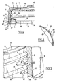
- the container 1 shown in the figures comprises on the one hand a body 2 having in the upper part an externally threaded neck 3, of axis X, and on the other hand a cover 4 having a skirt 5, threaded internally, configured to be screwed on the col 3.
- the container 1 may contain, for example, a cosmetic product, including care, including a cream or gel for the body, face or hair, but the invention is not limited to the packaging of a particular product.
- the inside diameter of the neck 3 can be relatively large, for example greater than or equal to 8 cm.
- the skirt 5 defines externally in the example considered the lateral surface 23 outer cover 4. It could be otherwise.
- the cover 4 internally houses a seal 6.
- the latter covers the bottom 7 of the lid, as can be seen in particular in Figures 1 and 4.
- the seal 6 is formed by a compressible disk which is retained by portions of annular bead 12 of the skirt 5, as can be seen in Figure 4.
- the bottom 7 of the lid 4 has, in its central part, a recess 15 and the seal 6 rests against the bottom 7 of the lid only in an annular zone device 16 of it.
- the skirt 5 of the lid 4 comprises, in the example under consideration, three threads 8 each extending over substantially one complete revolution and whose ends on the neck 3 are offset by 120 ° relative to each other around the X axis.
- the lateral surface 31 has a portion 33 with an outer periphery having a cross section, perpendicular to the X axis, circular.
- the shoulder 30 has a height h which varies circumferentially and in the example considered the shoulder 30 defines three helical ramps 36 which have the even no helix as the nets 9 and which each extend about 90 °.
- Each ramp 36 is connected by a recess 37 which extends substantially parallel to the axis X at a portion 39 of constant height and which extends angularly about 30 °, for example.
- the recess 37 may be, if necessary, slightly inclined according to the manner in which the demolding is carried out.
- the maximum height h max of the shoulder 30, measured at the radially inner edge of the upper face 32 is substantially 50% more than the minimum height h min also measured at the radially inner edge of the upper face 32.
- Each ramp 36 extends parallel to the nets 9 immediately higher.
- Two threads 9 are superposed vertically substantially above a recess 37, as can be seen in FIG. 5.
- the upper face 32 of the shoulder 30 defaults to level of a recess 37, with the net 9 immediately higher, a throat high enough to allow the engagement of a net 8 of the cover 4, as it is see figure 4.
- the radially inner surface 40 of the part lower part of the threaded skirt 5 can come into contact with the lateral surface 31 of the shoulder 30, which allows the latter to contribute to gradually centering the cover 4 on the This is particularly advantageous when a radial clearance exists between the cover 4 and the body 2 at the end of screwing, this radial clearance being for example more than one millimeter in the diametrical sense.
- the presence of the ramps 36 allows early centering and therefore reduces the risk that the lid is, at the end of screwing, with its axis offset laterally with respect to the X axis, which could affect the aesthetics of the container.
- the recesses 37 are not, in the example considered, stops fm stroke to immobilize in rotation the lid 4 relative to the body 2, this immobilization being ensured by support of the upper edge 17 of the neck 3 against the gasket 6.
- the body 2 is made in the example considered in one piece by molding plastic material, in particular by injection, or injection / blowing, for example into polypropylene, PVC or PET.
- the cover 4 is also made by injection molding, for example in polypropylene or HDPE, without the seal 6, then it is attached against the bottom 7.
- the shoulder 30 can be made differently and in particular in a circumferentially discontinuous manner, with for example recesses made in the ramps 36 in the circumferential direction.
- annular groove could be made at the base of the neck, dug in the lateral surface 31 of the shoulder.
- FIGS. 7 to 9 show a receptacle 50 conforming to another example of implementation of the invention.
- This container 50 comprises a body 51 comprising a portion 52 specific to contain product.
- the portion 52 is adapted to be placed in fluid communication with a housing 55 obtained by molding with portion 52, containing a spherical ball 56 free rise in rotation on itself inside the housing.
- the body 51 is polypropylene and the ball 56 in high density polyethylene. Other materials however can be used.
- the housing 55 is of spherical shape truncated at both ends according to the X axis of the body 51.
- An applicator portion 57 of the ball 56 emerges from the body 51 through an opening 53 formed by an edge of the housing 55.
- the container 50 has a lid 61 able to cover the portion applicator 57 of the ball.
- the cover 61 when mounted on the body 51, constrains the ball 56 in sealing abutment on at least two annular sealing zones 59, 60 formed by an inner surface 58 of the housing 55.
- An intermediate annular zone 69 of the inner surface 58 located between the two zones 59, 60 is not supported with the ball when the latter is in support sealing on the two annular sealing zones 59, 60.
- the two annular zones 59, 60 are located on the same side of a median plane of the applicator ball 56 perpendicular to the longitudinal axis X of the container, and remotely of said median plane.
- the two annular sealing zones are formed of edges 59, 60 obtained molding with housing.
- Each of the ridges 59 and 60 is formed without undercut, at the junction a first wall portion substantially parallel to the X axis, and a second portion substantially perpendicular to the X axis.
- the ridges are formed at the top (plus or less rounded) of material cords 67, 68, whose radial width may be included between 0.5 and 1 mm.
- the sealing is carried out by means of one or several elastically deformable lips carried by the inner surface of the housing 55.
- the cover 61 has an internally threaded skirt 70, configured to screw on a threaded portion 71 of the body 51.
- the threaded portion 71 extends below the constriction 64 and comprises, in the example considered, three helical threads 72.
- Each thread 72 extends, in the illustrated example, on an angular sector greater than or equal to 180 °, for example being about 225 °.
- Two successive helical threads 72 are superposed vertically on one angular sector of about 105 °.
- the threaded portion 71 has at its base an annular shoulder 30 connecting to an annular flange 34, like the container 1 described above.
- the shoulder 36 defines three helical ramps 36 each extending over a angular sector of about 120 °.
- the upper face 32 of the shoulder 30 forms with the net 72 immediately higher a space of height identical to that of the space between two neighboring nets 72.
- a thread of the threaded skirt 70 of the cover 61 can engage between the upper surface 32 of the shoulder 30 and a net 72 immediately superior.
- the cover 61 comprises a support structure which, during assembly of the cover, comes into engagement with the ball 56.
- This support structure comprises two concentric skirts 62, 63, centered on the axis X of the container: an inner skirt 62 and an outer skirt 63, the outer skirt participating at the centering of the cover 61 relative to the ball 56, and being of lower rigidity than the inner skirt.
- the cover 61 can be centered so precise when screwing, which ensures a reliable positioning of the cover 61 relative to the ball 56 and therefore satisfactory sealing of the ball 56 on the zones rings 59, 60.
- the body 51, the applicator ball 56 and the cover 61 are formed of at least one thermoplastic material selected from polyolefins, in particular polypropylene, high density or low polyethylene density, or mixtures thereof.
Landscapes
- Engineering & Computer Science (AREA)
- Mechanical Engineering (AREA)
- Closures For Containers (AREA)
- Road Signs Or Road Markings (AREA)
- Thermotherapy And Cooling Therapy Devices (AREA)
- Professional, Industrial, Or Sporting Protective Garments (AREA)
- Packages (AREA)
Abstract
Description
- un couvercle comportant une jupe filetée,
- un corps comportant une partie filetée sur laquelle la jupe filetée du couvercle peut se visser, la partie filetée comportant au moins un filet hélicoïdal, la partie filetée comportant à sa base un épaulement présentant une hauteur non constante lorsqu'on se déplace circonférentiellement sur la partie filetée, et une largeur sensiblement égale à celle du ou des filets de la partie filetée, la face supérieure de l'épaulement définit au moins deux rampes inclinées vers le haut lorsqu'on se déplace circonférentiellement sur la partie filetée, dans le sens du dévissage du couvercle, le corps du récipient comportant, autour de l'épaulement, un rebord dont la largeur correspond sensiblement à l'épaisseur du bord inférieur de la jupe filetée.
- la figure 1 est une vue schématique en perspective, avec arrachement du couvercle, d'un exemple de récipient réalisé conformément à l'invention,
- la figure 2 est une coupe axiale, schématique et partielle, du récipient de la figure 1,
- la figure 3 représente un détail de réalisation du col, en coupe axiale,
- la figure 4 représente en coupe axiale et partielle le couvercle sur le col,
- la figure 5 est une vue en perspective schématique et partielle, avec arrachement, du couvercle en fin de vissage sur le col,
- la figure 6 est une vue partielle de dessous du couvercle,
- la figure 7 est une vue schématique et partielle, en coupe axiale, d'un récipient conforme à un autre exemple de mise en oeuvre de l'invention, et
- les figures 8 et 9 représentent le corps du récipient de la figure 7, respectivement en vue de côté et en coupe.
Claims (37)
- Récipient (1 ; 50) comportant :un couvercle (4 ; 61) comportant une jupe filetée (5 ; 70),un corps (2 ; 51) comportant une partie filetée (3 ; 71) sur laquelle la jupe filetée (5 ; 70) du couvercle peut se visser, la partie filetée comportant à sa base un épaulement (30) présentant une hauteur (h) non constante lorsqu'on se déplace circonférentiellement sur la partie filetée, la face supérieure (32) de l'épaulement définissant au moins trois rampes (36) inclinées vers le haut lorsqu'on se déplace circonférentiellement sur la partie filetée, dans le sens du dévissage du couvercle, l'épaulement comportant une surface latérale, la jupe filetée du couvercle venant, en fm de vissage, en regard d'une portion de section transversale circulaire de la surface latérale de l'épaulement.
- Récipient selon la revendication 1, caractérisé par le fait que la face supérieure (32) est inclinée, au moins par endroits, radialement vers l'extérieur et vers le bas.
- Récipient selon la revendication 2, caractérisé par le fait que la face supérieure (32) est toujours inclinée radialement vers l'extérieur et vers le bas.
- Récipient selon l'une quelconque des revendications précédentes, caractérisé par le fait que la ou chaque rampe (36) s'étend sur un secteur angulaire compris entre 30 et 120°.
- Récipient selon la revendication 4, caractérisé par le fait que chaque rampe (36) s'étend sur un secteur angulaire de 90° environ.
- Récipient selon l'une quelconque des revendications précédentes, caractérisé par le fait que l'épaulement (30) présente, entre chaque rampe (36) et la suivante, une portion (39) de hauteur constante.
- Récipient selon la revendication 6, caractérisé par le fait que la portion (39) s'étend sur un secteur angulaire de 30° environ.
- Récipient selon la revendication 4, caractérisé par le fait que chaque rampe (36) s'étend sur un secteur angulaire de 120° environ.
- Récipient selon l'une quelconque des revendications précédentes, caractérisé par le fait que chaque rampe se raccorde à son extrémité supérieure à un décrochement (37) orienté sensiblement parallèlement à l'axe (X) de la partie filetée.
- Récipient selon l'une quelconque des revendications précédentes, caractérisé par le fait que la hauteur maximale (hmax) de l'épaulement annulaire (30) vaut au moins 50 % de plus que sa hauteur minimale (hmin).
- Récipient selon l'une quelconque des revendications précédentes, caractérisé par le fait que le corps (2) du récipient comporte, autour de l'épaulement (30), un rebord (34) dont la largeur correspond sensiblement à l'épaisseur du bord inférieur de la jupe filetée (5).
- Récipient selon l'une quelconque des revendications précédentes, caractérisé par le fait que la surface latérale annulaire (31) de l'épaulement (30) s'étend depuis la face supérieure de l'épaulement jusqu'au rebord annulaire (34) autour de l'épaulement, notamment sensiblement parallèlement à l'axe de la partie filetée.
- Récipient selon l'une quelconque des revendications précédentes, caractérisé par le fait que la partie filetée (3) comporte au moins un filet hélicoïdal (9).
- Récipient selon l'une quelconque des revendications précédentes, caractérisé par le fait que la partie filetée (3) comporte au moins deux filets hélicoïdaux (9).
- Récipient selon la revendication 14, caractérisé par le fait que la partie filetée (3) comporte trois filets hélicoïdaux (9).
- Récipient selon la revendication 15, caractérisé par le fait que chaque filet (9) s'étend sur un secteur angulaire de 120° environ.
- Récipient selon l'une quelconque des revendications 13 à 16, caractérisé par le fait que la largeur de l'épaulement (30) est sensiblement égale à celle du ou des filets (9) de la partie filetée.
- Récipient selon l'une quelconque des revendications précédentes, caractérisé par le fait que chaque rampe (36) présente le même pas d'hélice que le ou les filets hélicoïdaux de la partie filetée.
- Récipient selon l'une quelconque des revendications précédentes, caractérisé par le fait que la jupe filetée (5) du couvercle comporte sur sa tranche des indentations (20).
- Récipient selon l'une quelconque des revendications précédentes, caractérisé par le fait que la jupe filetée (5) du couvercle comporte un chanfrein (14) radialement intérieur à son extrémité inférieure.
- Récipient selon l'une quelconque des revendications précédentes, caractérisé par le fait que le corps (2) est réalisé d'un seul tenant par moulage de matière plastique, notamment par injection.
- Récipient selon la revendication 20, caractérisé par le fait que le corps est réalisé en polypropylène.
- Récipient selon l'une quelconque des revendications précédentes, caractérisé par le fait que la jupe filetée (5) est réalisée par moulage de matière plastique.
- Récipient selon la revendication précédente, caractérisé par le fait que la jupe filetée (5) définit extérieurement la surface latérale (23) du couvercle (4).
- Récipient selon l'une quelconque des revendications précédentes, caractérisé par le fait que le couvercle loge un joint d'étanchéité (6).
- Récipient selon la revendication précédente, caractérisé par le fait que le joint d'étanchéité (6) couvre entièrement le fond (7) du couvercle.
- Récipient selon l'une quelconque des revendications 1 à 24, caractérisé par le fait que le corps (51) du récipient comporte un logement contenant une bille sphérique montée en libre rotation à l'intérieur du logement, une portion applicatrice de la bille émergeant hors du corps au travers d'une ouverture formée par un bord du logement.
- Récipient selon la revendication précédente, caractérisé par le fait que le couvercle (61) comporte au moins un jupe annulaire, par exemple deux jupes annulaires, aptes à contraindre la bille en appui étanche sur au moins une zone annulaire d'étanchéité, notamment au moins deux zones annulaires d'étanchéité, formées par une surface intérieure du logement.
- Récipient selon l'une des revendications 27 et 28, caractérisé par le fait que la surface intérieure (58) du logement (55) forme une zone annulaire intermédiaire située entre lesdites deux zones annulaires d'étanchéité, cette zone intermédiaire n'étant pas au contact de la bille lorsque cette dernière est en appui étanche sur les deux zones annulaires d'étanchéité.
- Récipient selon l'une quelconque des revendications précédentes, caractérisé par le fait que le diamètre intérieur de la partie filetée (3) est supérieur à 4 cm, mieux 6 cm, mieux encore 8 cm.
- Récipient selon l'une quelconque des revendications 1 à 30, caractérisé par le fait que la jupe filetée (5) comporte plusieurs filets hélicoïdaux (8), notamment trois filets (8).
- Récipient selon la revendication 31, caractérisé par le fait que chaque filet (8) s'étend sur un secteur angulaire sensiblement égal à 120°.
- Récipient selon l'une quelconque des revendications 1 à 32, caractérisé par le fait que la partie filetée (3) et le couvercle (4) sont configurés de telle sorte qu'il subsiste après vissage du couvercle (4) un jeu radial sensible entre le couvercle (4) et la partie filetée (3).
- Récipient selon l'une quelconque des revendications précédentes, caractérisé par le fait que l'épaulement (30) est dépourvu de surface, notamment sensiblement parallèle à l'axe de la partie filetée, servant de butée de fin de course permettant d'immobiliser en rotation le couvercle par rapport au corps.
- Récipient selon l'une quelconque des revendications précédentes, caractérisé par le fait que les rampes (36) sont situées axialement entre une ouverture du corps (2 ; 51) et la portion de section transversale circulaire de la surface latérale de l'épaulement.
- Récipient selon l'une quelconque des revendications précédentes, caractérisé par le fait qu'il contient un produit cosmétique, y compris de soin.
- Récipient comportant :un couvercle (4) comportant une jupe filetée (5),un corps (2) comportant une partie filetée (3) sur laquelle la jupe filetée (5) du couvercle peut se visser, la partie filetée (3) comportant au moins un filet hélicoïdal (9), la partie filetée comportant à sa base un épaulement (30) présentant une hauteur (h) non constante lorsqu'on se déplace circonférentiellement sur la partie filetée, et une largeur sensiblement égale à celle du ou des filets (9) de la partie filetée (3), la face supérieure (32) de l'épaulement définit au moins deux rampes (36) inclinées vers le haut lorsqu'on se déplace circonférentiellement sur la partie filetée, dans le sens du dévissage du couvercle, le corps (2) du récipient comportant, autour de l'épaulement (30), un rebord (34) dont la largeur correspond sensiblement à l'épaisseur du bord inférieur de la jupe filetée (5).
Applications Claiming Priority (2)
| Application Number | Priority Date | Filing Date | Title |
|---|---|---|---|
| FR0401970A FR2866862B1 (fr) | 2004-02-26 | 2004-02-26 | Recipient comportant un corps et un couvercle agence pour se visser sur le corps |
| FR0401970 | 2004-02-26 |
Publications (2)
| Publication Number | Publication Date |
|---|---|
| EP1568616A1 true EP1568616A1 (fr) | 2005-08-31 |
| EP1568616B1 EP1568616B1 (fr) | 2010-07-07 |
Family
ID=34746450
Family Applications (1)
| Application Number | Title | Priority Date | Filing Date |
|---|---|---|---|
| EP05300148A Expired - Lifetime EP1568616B1 (fr) | 2004-02-26 | 2005-02-25 | Récipient comportant un corps et un couvercle agencé pour se visser sur le corps |
Country Status (5)
| Country | Link |
|---|---|
| EP (1) | EP1568616B1 (fr) |
| AT (1) | ATE473181T1 (fr) |
| DE (1) | DE602005022134D1 (fr) |
| ES (1) | ES2348158T3 (fr) |
| FR (1) | FR2866862B1 (fr) |
Cited By (1)
| Publication number | Priority date | Publication date | Assignee | Title |
|---|---|---|---|---|
| FR3054959A1 (fr) * | 2016-08-12 | 2018-02-16 | L'oreal | Couvercle pour recipient de stockage d'un produit, notamment d'un produit cosmetique |
Citations (12)
| Publication number | Priority date | Publication date | Assignee | Title |
|---|---|---|---|---|
| GB1283838A (en) * | 1969-05-06 | 1972-08-02 | Courreges Parfums | A container |
| AU8103875A (en) | 1975-05-12 | 1976-11-18 | Sunbeam Plastics Corp | Child resistant closure for liquid containers |
| US4456137A (en) | 1982-07-19 | 1984-06-26 | Data Packaging Corporation | Venting arrangement for covered containers |
| FR2542706A1 (fr) | 1983-03-16 | 1984-09-21 | Zeller Plastik Koehn Graebner | Fermeture avec filetage a entrees multiples |
| DE3814786A1 (de) | 1988-04-30 | 1989-11-23 | Weener Plastik Gmbh Co Kg | Behaeltnis, insbesondere flasche |
| DE3837453A1 (de) | 1988-11-04 | 1990-05-10 | Geka Brush Georg Karl Gmbh | Kosmetikeinheit, insbesondere nagellackeinheit |
| EP0528265A1 (fr) | 1991-08-15 | 1993-02-24 | Bramlage GmbH | Applicateur à bille |
| US5213225A (en) | 1990-05-30 | 1993-05-25 | Beeson And Sons Limited | Container and closure |
| EP0787660A1 (fr) | 1996-01-30 | 1997-08-06 | Owens-Illinois Closure Inc., | Fermeture à vis de protection pour enfants |
| US6105801A (en) | 1998-08-04 | 2000-08-22 | Rexam Medical Packaging, Inc. | Container having collapsible neck finish |
| DE19947388A1 (de) | 1999-10-01 | 2001-04-12 | Kunststoffwerk Kutterer Gmbh | Behältnis, insbesondere Tube mit Drehverschluss |
| JP2001122301A (ja) | 1999-10-22 | 2001-05-08 | Yoshino Kogyosho Co Ltd | キャップ付き容器 |
-
2004
- 2004-02-26 FR FR0401970A patent/FR2866862B1/fr not_active Expired - Fee Related
-
2005
- 2005-02-25 ES ES05300148T patent/ES2348158T3/es not_active Expired - Lifetime
- 2005-02-25 DE DE602005022134T patent/DE602005022134D1/de not_active Expired - Lifetime
- 2005-02-25 AT AT05300148T patent/ATE473181T1/de not_active IP Right Cessation
- 2005-02-25 EP EP05300148A patent/EP1568616B1/fr not_active Expired - Lifetime
Patent Citations (12)
| Publication number | Priority date | Publication date | Assignee | Title |
|---|---|---|---|---|
| GB1283838A (en) * | 1969-05-06 | 1972-08-02 | Courreges Parfums | A container |
| AU8103875A (en) | 1975-05-12 | 1976-11-18 | Sunbeam Plastics Corp | Child resistant closure for liquid containers |
| US4456137A (en) | 1982-07-19 | 1984-06-26 | Data Packaging Corporation | Venting arrangement for covered containers |
| FR2542706A1 (fr) | 1983-03-16 | 1984-09-21 | Zeller Plastik Koehn Graebner | Fermeture avec filetage a entrees multiples |
| DE3814786A1 (de) | 1988-04-30 | 1989-11-23 | Weener Plastik Gmbh Co Kg | Behaeltnis, insbesondere flasche |
| DE3837453A1 (de) | 1988-11-04 | 1990-05-10 | Geka Brush Georg Karl Gmbh | Kosmetikeinheit, insbesondere nagellackeinheit |
| US5213225A (en) | 1990-05-30 | 1993-05-25 | Beeson And Sons Limited | Container and closure |
| EP0528265A1 (fr) | 1991-08-15 | 1993-02-24 | Bramlage GmbH | Applicateur à bille |
| EP0787660A1 (fr) | 1996-01-30 | 1997-08-06 | Owens-Illinois Closure Inc., | Fermeture à vis de protection pour enfants |
| US6105801A (en) | 1998-08-04 | 2000-08-22 | Rexam Medical Packaging, Inc. | Container having collapsible neck finish |
| DE19947388A1 (de) | 1999-10-01 | 2001-04-12 | Kunststoffwerk Kutterer Gmbh | Behältnis, insbesondere Tube mit Drehverschluss |
| JP2001122301A (ja) | 1999-10-22 | 2001-05-08 | Yoshino Kogyosho Co Ltd | キャップ付き容器 |
Cited By (1)
| Publication number | Priority date | Publication date | Assignee | Title |
|---|---|---|---|---|
| FR3054959A1 (fr) * | 2016-08-12 | 2018-02-16 | L'oreal | Couvercle pour recipient de stockage d'un produit, notamment d'un produit cosmetique |
Also Published As
| Publication number | Publication date |
|---|---|
| ES2348158T3 (es) | 2010-11-30 |
| DE602005022134D1 (de) | 2010-08-19 |
| FR2866862B1 (fr) | 2007-04-27 |
| FR2866862A1 (fr) | 2005-09-02 |
| EP1568616B1 (fr) | 2010-07-07 |
| ATE473181T1 (de) | 2010-07-15 |
Similar Documents
| Publication | Publication Date | Title |
|---|---|---|
| CA2016977C (fr) | Dispositif applicateur pour liquide, comportant un dome en matiere poreuse | |
| CA2235081C (fr) | Conditionnement pour le melange extemporane de deux produits | |
| EP1894848B1 (fr) | Dispositif de conditionnement à double enveloppe | |
| EP0975526B1 (fr) | Capsule de distribution a etancheite amelioree | |
| EP1481607B2 (fr) | Dispositif de conditionnement et d'application d'un produit, comportant un organe d'essorage | |
| EP1193186A2 (fr) | Dispositif pour la fixation réversible d'un récipient sur un support et récipient équipé d'un tel dispositif. | |
| FR2928629A1 (fr) | Dispositif de protection d'un recipient de produit, notamment d'un produit cosmetique. | |
| EP2111363B1 (fr) | Bouchon sans joint rapporte | |
| EP0839735A1 (fr) | Capsule articulée à élément de liaison amélioré | |
| EP0816245A1 (fr) | Tête de distibution d'un produit liquide à consistance visqueuse comportant un organe élastique de fermeture, et ensemble de distribution ainsi équipé | |
| CA2337184C (fr) | Dispositif de conditionnement et d'application comportant un element formant reservoir intermediaire | |
| EP0948273B1 (fr) | Boitier de maquillage a joint d'etancheite | |
| EP4375213B1 (fr) | Godet rechargeable pour pot distributeur de produit cosmétique | |
| FR2788255A1 (fr) | Boitier a fermeture etanche | |
| FR3127485A1 (fr) | Coque d’un dispositif rechargeable de conditionnement d’un produit cosmétique et dispositif de conditionnement associé | |
| FR3004892A1 (fr) | Dispositif de piegeage a collier articule | |
| FR3064162A1 (fr) | Capsule de fermeture pour dispositif de conditionnement d'un produit, notamment d'un produit cosmetique | |
| FR2979099A1 (fr) | Tete de distribution de produit pour un recipient et dispositif de distribution associe | |
| FR2879906A1 (fr) | Ensemble de conditionnement et d'application d'un produit cosmetique | |
| FR2551030A1 (fr) | Recipient-tube destine a contenir de la matiere semi-fluide | |
| EP1568616B1 (fr) | Récipient comportant un corps et un couvercle agencé pour se visser sur le corps | |
| EP1910183A1 (fr) | Bouchon a moyen verseur | |
| FR2567106A1 (fr) | Couvercle tournant d'un contenant | |
| FR2920747A1 (fr) | Capot comportant un insert et un habillage surmoule sur l'insert | |
| EP0852205A1 (fr) | Capsule pour le bouchage d'un recipient dont le col est equipe d'une collerette |
Legal Events
| Date | Code | Title | Description |
|---|---|---|---|
| PUAI | Public reference made under article 153(3) epc to a published international application that has entered the european phase |
Free format text: ORIGINAL CODE: 0009012 |
|
| 17P | Request for examination filed |
Effective date: 20050226 |
|
| AK | Designated contracting states |
Kind code of ref document: A1 Designated state(s): AT BE BG CH CY CZ DE DK EE ES FI FR GB GR HU IE IS IT LI LT LU MC NL PL PT RO SE SI SK TR |
|
| AX | Request for extension of the european patent |
Extension state: AL BA HR LV MK YU |
|
| AKX | Designation fees paid |
Designated state(s): AT BE BG CH CY CZ DE DK EE ES FI FR GB GR HU IE IS IT LI LT LU MC NL PL PT RO SE SI SK TR |
|
| 17Q | First examination report despatched |
Effective date: 20080508 |
|
| GRAP | Despatch of communication of intention to grant a patent |
Free format text: ORIGINAL CODE: EPIDOSNIGR1 |
|
| RIN1 | Information on inventor provided before grant (corrected) |
Inventor name: EVAIN, GABRIEL |
|
| GRAS | Grant fee paid |
Free format text: ORIGINAL CODE: EPIDOSNIGR3 |
|
| GRAA | (expected) grant |
Free format text: ORIGINAL CODE: 0009210 |
|
| AK | Designated contracting states |
Kind code of ref document: B1 Designated state(s): AT BE BG CH CY CZ DE DK EE ES FI FR GB GR HU IE IS IT LI LT LU MC NL PL PT RO SE SI SK TR |
|
| REG | Reference to a national code |
Ref country code: GB Ref legal event code: FG4D Free format text: NOT ENGLISH |
|
| REG | Reference to a national code |
Ref country code: CH Ref legal event code: EP |
|
| REG | Reference to a national code |
Ref country code: IE Ref legal event code: FG4D |
|
| REF | Corresponds to: |
Ref document number: 602005022134 Country of ref document: DE Date of ref document: 20100819 Kind code of ref document: P |
|
| REG | Reference to a national code |
Ref country code: NL Ref legal event code: VDEP Effective date: 20100707 |
|
| PG25 | Lapsed in a contracting state [announced via postgrant information from national office to epo] |
Ref country code: SI Free format text: LAPSE BECAUSE OF FAILURE TO SUBMIT A TRANSLATION OF THE DESCRIPTION OR TO PAY THE FEE WITHIN THE PRESCRIBED TIME-LIMIT Effective date: 20100707 |
|
| LTIE | Lt: invalidation of european patent or patent extension |
Effective date: 20100707 |
|
| PG25 | Lapsed in a contracting state [announced via postgrant information from national office to epo] |
Ref country code: NL Free format text: LAPSE BECAUSE OF FAILURE TO SUBMIT A TRANSLATION OF THE DESCRIPTION OR TO PAY THE FEE WITHIN THE PRESCRIBED TIME-LIMIT Effective date: 20100707 Ref country code: LT Free format text: LAPSE BECAUSE OF FAILURE TO SUBMIT A TRANSLATION OF THE DESCRIPTION OR TO PAY THE FEE WITHIN THE PRESCRIBED TIME-LIMIT Effective date: 20100707 Ref country code: FI Free format text: LAPSE BECAUSE OF FAILURE TO SUBMIT A TRANSLATION OF THE DESCRIPTION OR TO PAY THE FEE WITHIN THE PRESCRIBED TIME-LIMIT Effective date: 20100707 Ref country code: AT Free format text: LAPSE BECAUSE OF FAILURE TO SUBMIT A TRANSLATION OF THE DESCRIPTION OR TO PAY THE FEE WITHIN THE PRESCRIBED TIME-LIMIT Effective date: 20100707 |
|
| REG | Reference to a national code |
Ref country code: IE Ref legal event code: FD4D |
|
| PG25 | Lapsed in a contracting state [announced via postgrant information from national office to epo] |
Ref country code: CY Free format text: LAPSE BECAUSE OF FAILURE TO SUBMIT A TRANSLATION OF THE DESCRIPTION OR TO PAY THE FEE WITHIN THE PRESCRIBED TIME-LIMIT Effective date: 20100707 Ref country code: PL Free format text: LAPSE BECAUSE OF FAILURE TO SUBMIT A TRANSLATION OF THE DESCRIPTION OR TO PAY THE FEE WITHIN THE PRESCRIBED TIME-LIMIT Effective date: 20100707 Ref country code: PT Free format text: LAPSE BECAUSE OF FAILURE TO SUBMIT A TRANSLATION OF THE DESCRIPTION OR TO PAY THE FEE WITHIN THE PRESCRIBED TIME-LIMIT Effective date: 20101108 Ref country code: BG Free format text: LAPSE BECAUSE OF FAILURE TO SUBMIT A TRANSLATION OF THE DESCRIPTION OR TO PAY THE FEE WITHIN THE PRESCRIBED TIME-LIMIT Effective date: 20101007 Ref country code: IS Free format text: LAPSE BECAUSE OF FAILURE TO SUBMIT A TRANSLATION OF THE DESCRIPTION OR TO PAY THE FEE WITHIN THE PRESCRIBED TIME-LIMIT Effective date: 20101107 |
|
| PG25 | Lapsed in a contracting state [announced via postgrant information from national office to epo] |
Ref country code: GR Free format text: LAPSE BECAUSE OF FAILURE TO SUBMIT A TRANSLATION OF THE DESCRIPTION OR TO PAY THE FEE WITHIN THE PRESCRIBED TIME-LIMIT Effective date: 20101008 Ref country code: SE Free format text: LAPSE BECAUSE OF FAILURE TO SUBMIT A TRANSLATION OF THE DESCRIPTION OR TO PAY THE FEE WITHIN THE PRESCRIBED TIME-LIMIT Effective date: 20100707 |
|
| PG25 | Lapsed in a contracting state [announced via postgrant information from national office to epo] |
Ref country code: DK Free format text: LAPSE BECAUSE OF FAILURE TO SUBMIT A TRANSLATION OF THE DESCRIPTION OR TO PAY THE FEE WITHIN THE PRESCRIBED TIME-LIMIT Effective date: 20100707 Ref country code: IE Free format text: LAPSE BECAUSE OF FAILURE TO SUBMIT A TRANSLATION OF THE DESCRIPTION OR TO PAY THE FEE WITHIN THE PRESCRIBED TIME-LIMIT Effective date: 20100707 |
|
| PLBE | No opposition filed within time limit |
Free format text: ORIGINAL CODE: 0009261 |
|
| STAA | Information on the status of an ep patent application or granted ep patent |
Free format text: STATUS: NO OPPOSITION FILED WITHIN TIME LIMIT |
|
| PG25 | Lapsed in a contracting state [announced via postgrant information from national office to epo] |
Ref country code: RO Free format text: LAPSE BECAUSE OF FAILURE TO SUBMIT A TRANSLATION OF THE DESCRIPTION OR TO PAY THE FEE WITHIN THE PRESCRIBED TIME-LIMIT Effective date: 20100707 Ref country code: CZ Free format text: LAPSE BECAUSE OF FAILURE TO SUBMIT A TRANSLATION OF THE DESCRIPTION OR TO PAY THE FEE WITHIN THE PRESCRIBED TIME-LIMIT Effective date: 20100707 Ref country code: EE Free format text: LAPSE BECAUSE OF FAILURE TO SUBMIT A TRANSLATION OF THE DESCRIPTION OR TO PAY THE FEE WITHIN THE PRESCRIBED TIME-LIMIT Effective date: 20100707 Ref country code: SK Free format text: LAPSE BECAUSE OF FAILURE TO SUBMIT A TRANSLATION OF THE DESCRIPTION OR TO PAY THE FEE WITHIN THE PRESCRIBED TIME-LIMIT Effective date: 20100707 |
|
| 26N | No opposition filed |
Effective date: 20110408 |
|
| REG | Reference to a national code |
Ref country code: DE Ref legal event code: R097 Ref document number: 602005022134 Country of ref document: DE Effective date: 20110408 |
|
| BERE | Be: lapsed |
Owner name: L'OREAL Effective date: 20110228 |
|
| PG25 | Lapsed in a contracting state [announced via postgrant information from national office to epo] |
Ref country code: MC Free format text: LAPSE BECAUSE OF NON-PAYMENT OF DUE FEES Effective date: 20110228 |
|
| REG | Reference to a national code |
Ref country code: CH Ref legal event code: PL |
|
| PG25 | Lapsed in a contracting state [announced via postgrant information from national office to epo] |
Ref country code: CH Free format text: LAPSE BECAUSE OF NON-PAYMENT OF DUE FEES Effective date: 20110228 Ref country code: LI Free format text: LAPSE BECAUSE OF NON-PAYMENT OF DUE FEES Effective date: 20110228 |
|
| PG25 | Lapsed in a contracting state [announced via postgrant information from national office to epo] |
Ref country code: BE Free format text: LAPSE BECAUSE OF NON-PAYMENT OF DUE FEES Effective date: 20110228 |
|
| PG25 | Lapsed in a contracting state [announced via postgrant information from national office to epo] |
Ref country code: LU Free format text: LAPSE BECAUSE OF NON-PAYMENT OF DUE FEES Effective date: 20110225 |
|
| PG25 | Lapsed in a contracting state [announced via postgrant information from national office to epo] |
Ref country code: TR Free format text: LAPSE BECAUSE OF FAILURE TO SUBMIT A TRANSLATION OF THE DESCRIPTION OR TO PAY THE FEE WITHIN THE PRESCRIBED TIME-LIMIT Effective date: 20100707 |
|
| PG25 | Lapsed in a contracting state [announced via postgrant information from national office to epo] |
Ref country code: HU Free format text: LAPSE BECAUSE OF FAILURE TO SUBMIT A TRANSLATION OF THE DESCRIPTION OR TO PAY THE FEE WITHIN THE PRESCRIBED TIME-LIMIT Effective date: 20100707 |
|
| REG | Reference to a national code |
Ref country code: FR Ref legal event code: PLFP Year of fee payment: 12 |
|
| REG | Reference to a national code |
Ref country code: FR Ref legal event code: PLFP Year of fee payment: 13 |
|
| REG | Reference to a national code |
Ref country code: FR Ref legal event code: PLFP Year of fee payment: 14 |
|
| PGFP | Annual fee paid to national office [announced via postgrant information from national office to epo] |
Ref country code: DE Payment date: 20200211 Year of fee payment: 16 Ref country code: ES Payment date: 20200302 Year of fee payment: 16 Ref country code: GB Payment date: 20200212 Year of fee payment: 16 Ref country code: IT Payment date: 20200128 Year of fee payment: 16 |
|
| PGFP | Annual fee paid to national office [announced via postgrant information from national office to epo] |
Ref country code: FR Payment date: 20200113 Year of fee payment: 16 |
|
| REG | Reference to a national code |
Ref country code: DE Ref legal event code: R119 Ref document number: 602005022134 Country of ref document: DE |
|
| GBPC | Gb: european patent ceased through non-payment of renewal fee |
Effective date: 20210225 |
|
| PG25 | Lapsed in a contracting state [announced via postgrant information from national office to epo] |
Ref country code: DE Free format text: LAPSE BECAUSE OF NON-PAYMENT OF DUE FEES Effective date: 20210901 Ref country code: GB Free format text: LAPSE BECAUSE OF NON-PAYMENT OF DUE FEES Effective date: 20210225 Ref country code: FR Free format text: LAPSE BECAUSE OF NON-PAYMENT OF DUE FEES Effective date: 20210228 |
|
| PG25 | Lapsed in a contracting state [announced via postgrant information from national office to epo] |
Ref country code: IT Free format text: LAPSE BECAUSE OF NON-PAYMENT OF DUE FEES Effective date: 20210225 |
|
| REG | Reference to a national code |
Ref country code: ES Ref legal event code: FD2A Effective date: 20220513 |
|
| PG25 | Lapsed in a contracting state [announced via postgrant information from national office to epo] |
Ref country code: ES Free format text: LAPSE BECAUSE OF NON-PAYMENT OF DUE FEES Effective date: 20210226 |