EP1568581B1 - Reinigungswagen - Google Patents
Reinigungswagen Download PDFInfo
- Publication number
- EP1568581B1 EP1568581B1 EP04004139A EP04004139A EP1568581B1 EP 1568581 B1 EP1568581 B1 EP 1568581B1 EP 04004139 A EP04004139 A EP 04004139A EP 04004139 A EP04004139 A EP 04004139A EP 1568581 B1 EP1568581 B1 EP 1568581B1
- Authority
- EP
- European Patent Office
- Prior art keywords
- base
- wheels
- cleaning trolley
- cleaning
- trolley according
- Prior art date
- Legal status (The legal status is an assumption and is not a legal conclusion. Google has not performed a legal analysis and makes no representation as to the accuracy of the status listed.)
- Expired - Lifetime
Links
Images


Classifications
-
- A—HUMAN NECESSITIES
- A61—MEDICAL OR VETERINARY SCIENCE; HYGIENE
- A61G—TRANSPORT, PERSONAL CONVEYANCES, OR ACCOMMODATION SPECIALLY ADAPTED FOR PATIENTS OR DISABLED PERSONS; OPERATING TABLES OR CHAIRS; CHAIRS FOR DENTISTRY; FUNERAL DEVICES
- A61G12/00—Accommodation for nursing, e.g. in hospitals, not covered by groups A61G1/00 - A61G11/00, e.g. trolleys for transport of medicaments or food; Prescription lists
- A61G12/001—Trolleys for transport of medicaments, food, linen, nursing supplies
-
- B—PERFORMING OPERATIONS; TRANSPORTING
- B62—LAND VEHICLES FOR TRAVELLING OTHERWISE THAN ON RAILS
- B62B—HAND-PROPELLED VEHICLES, e.g. HAND CARTS OR PERAMBULATORS; SLEDGES
- B62B3/00—Hand carts having more than one axis carrying transport wheels; Steering devices therefor; Equipment therefor
- B62B3/006—Hand carts having more than one axis carrying transport wheels; Steering devices therefor; Equipment therefor for stacking objects like trays, bobbins, chains
-
- B—PERFORMING OPERATIONS; TRANSPORTING
- B62—LAND VEHICLES FOR TRAVELLING OTHERWISE THAN ON RAILS
- B62B—HAND-PROPELLED VEHICLES, e.g. HAND CARTS OR PERAMBULATORS; SLEDGES
- B62B3/00—Hand carts having more than one axis carrying transport wheels; Steering devices therefor; Equipment therefor
- B62B3/008—Hand carts having more than one axis carrying transport wheels; Steering devices therefor; Equipment therefor having more than two axes
-
- B—PERFORMING OPERATIONS; TRANSPORTING
- B62—LAND VEHICLES FOR TRAVELLING OTHERWISE THAN ON RAILS
- B62B—HAND-PROPELLED VEHICLES, e.g. HAND CARTS OR PERAMBULATORS; SLEDGES
- B62B3/00—Hand carts having more than one axis carrying transport wheels; Steering devices therefor; Equipment therefor
- B62B3/02—Hand carts having more than one axis carrying transport wheels; Steering devices therefor; Equipment therefor involving parts being adjustable, collapsible, attachable, detachable or convertible
-
- B—PERFORMING OPERATIONS; TRANSPORTING
- B62—LAND VEHICLES FOR TRAVELLING OTHERWISE THAN ON RAILS
- B62B—HAND-PROPELLED VEHICLES, e.g. HAND CARTS OR PERAMBULATORS; SLEDGES
- B62B5/00—Accessories or details specially adapted for hand carts
- B62B5/0026—Propulsion aids
-
- B—PERFORMING OPERATIONS; TRANSPORTING
- B62—LAND VEHICLES FOR TRAVELLING OTHERWISE THAN ON RAILS
- B62B—HAND-PROPELLED VEHICLES, e.g. HAND CARTS OR PERAMBULATORS; SLEDGES
- B62B5/00—Accessories or details specially adapted for hand carts
- B62B5/0026—Propulsion aids
- B62B5/0033—Electric motors
- B62B5/0036—Arrangements of motors
- B62B5/0043—One motor drives one wheel
-
- B—PERFORMING OPERATIONS; TRANSPORTING
- B62—LAND VEHICLES FOR TRAVELLING OTHERWISE THAN ON RAILS
- B62D—MOTOR VEHICLES; TRAILERS
- B62D51/00—Motor vehicles characterised by the driver not being seated
- B62D51/02—Motor vehicles characterised by the driver not being seated the driver standing in the vehicle
-
- B—PERFORMING OPERATIONS; TRANSPORTING
- B62—LAND VEHICLES FOR TRAVELLING OTHERWISE THAN ON RAILS
- B62D—MOTOR VEHICLES; TRAILERS
- B62D51/00—Motor vehicles characterised by the driver not being seated
- B62D51/04—Motor vehicles characterised by the driver not being seated the driver walking
-
- B—PERFORMING OPERATIONS; TRANSPORTING
- B62—LAND VEHICLES FOR TRAVELLING OTHERWISE THAN ON RAILS
- B62D—MOTOR VEHICLES; TRAILERS
- B62D61/00—Motor vehicles or trailers, characterised by the arrangement or number of wheels, not otherwise provided for, e.g. four wheels in diamond pattern
- B62D61/02—Motor vehicles or trailers, characterised by the arrangement or number of wheels, not otherwise provided for, e.g. four wheels in diamond pattern with two road wheels in tandem on the longitudinal centre line of the vehicle
- B62D61/04—Motor vehicles or trailers, characterised by the arrangement or number of wheels, not otherwise provided for, e.g. four wheels in diamond pattern with two road wheels in tandem on the longitudinal centre line of the vehicle with two other wheels which are coaxial
-
- A—HUMAN NECESSITIES
- A61—MEDICAL OR VETERINARY SCIENCE; HYGIENE
- A61G—TRANSPORT, PERSONAL CONVEYANCES, OR ACCOMMODATION SPECIALLY ADAPTED FOR PATIENTS OR DISABLED PERSONS; OPERATING TABLES OR CHAIRS; CHAIRS FOR DENTISTRY; FUNERAL DEVICES
- A61G7/00—Beds specially adapted for nursing; Devices for lifting patients or disabled persons
- A61G7/08—Apparatus for transporting beds
-
- B—PERFORMING OPERATIONS; TRANSPORTING
- B62—LAND VEHICLES FOR TRAVELLING OTHERWISE THAN ON RAILS
- B62B—HAND-PROPELLED VEHICLES, e.g. HAND CARTS OR PERAMBULATORS; SLEDGES
- B62B2202/00—Indexing codes relating to type or characteristics of transported articles
- B62B2202/50—Cleaning or gardening articles
-
- B—PERFORMING OPERATIONS; TRANSPORTING
- B62—LAND VEHICLES FOR TRAVELLING OTHERWISE THAN ON RAILS
- B62B—HAND-PROPELLED VEHICLES, e.g. HAND CARTS OR PERAMBULATORS; SLEDGES
- B62B2301/00—Wheel arrangements; Steering; Stability; Wheel suspension
- B62B2301/08—Wheel arrangements; Steering; Stability; Wheel suspension comprising additional wheels to increase stability
-
- B—PERFORMING OPERATIONS; TRANSPORTING
- B62—LAND VEHICLES FOR TRAVELLING OTHERWISE THAN ON RAILS
- B62B—HAND-PROPELLED VEHICLES, e.g. HAND CARTS OR PERAMBULATORS; SLEDGES
- B62B5/00—Accessories or details specially adapted for hand carts
- B62B5/08—Children's seats ; Seats or supports for other persons
- B62B5/087—Platforms to stand upon
Definitions
- the present invention relates to a cleaning trolley, with a base, at least three wheels arranged laterally or below the base and a structure arranged above the base for receiving cleaning utensils and a handle.
- the base which is usually designed as a load-bearing platform or frame arrangement, can consist of a plastic or metal plate or a metal tube structures.
- the structure for receiving the cleaning utensils is usually formed by a column construction or a frame arrangement of jet pipe, which can be made variable depending on the purpose and often can be assembled according to a kind of modular system.
- Object of the present invention is therefore to provide a cleaning trolley, which is even in heavy load to save energy and fatigue-free and is simple in construction.
- Transport trolleys for carrying loads driven by an electric motor are standard equipment of industrial companies. However, they are technically very complex and have relatively large-volume drives. Such constructions are not suitable for the use of cleaning trolleys, as they are designed comparatively filigree and the cleaning utensils must be arranged to achieve a fatigue-free use ergonomic considerations, so that there is no space for conventional drives.
- the invention is based on the idea of creating a kind of "underfloor construction” instead of conventional heavy industrial drives or complex wheel hub drives, which utilizes the space under the base, which is required anyway for the necessary ground clearance of the cleaning cart, and uses as little space as possible in the area above Base provided construction requires.
- the accumulator arrangement can optionally also be arranged in the region of the upper side of the base between the cleaning utensils.
- any suitable control can be provided for controlling the electric motor or motors.
- a thrust sensor which supplies the electric motor or motors with energy from the accumulator arrangement as soon as the operator exerts a thrust force on the handle or the carriage.
- the control arrangement connected to the electric motor (s) and the accumulator arrangement consists of a simple actuating device in the region of the handle, which may have as a control element, for example, a slide control, rotary handle, joystick or the like.
- the wheels can be arranged in any desired manner. It is advantageous, however, if - seen in the direction of travel - the fixed wheels approximately in the middle of the car in the region of the side edges of the base and a respective movable wheel is arranged centrally in the region of the front edge and the rear edge of the base.
- a structurally particularly simple and with respect to the center of gravity optimal arrangement is achieved when the heavy elements of the drive, such as the electric motor, the gear assembly and the accumulator assembly approximately in the middle under the base, i. the platform or the frame assembly are arranged.
- the most diverse constellations are available.
- a particularly flat and the ground clearance only slightly reducing arrangement is achieved when approximately two electric motors are arranged approximately in the middle of the base, which are in operative connection via a respective transmission with one of the fixed wheels.
- the distance from the parking station to the place of use is often several hundred meters, in special cases several kilometers.
- the standing device can be configured in the most diverse ways. For example, it is possible to integrate the stand device into the base.
- the stand device is particularly advantageous, however, to design the stand device as a platform which can be coupled to the base, which in turn is equipped with wheels.
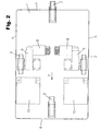
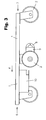
- the cleaning trolley consists of a base in the form of a platform 1, wheels 2 arranged underneath the platform 1, and a superstructure 3 arranged above the platform 1, which for the sake of clarity is only partly constructed and unloaded, ie. is shown without cleaning utensils.
- the structure 3 is equipped with a handle 4 in the form of a handle.
- the cleaning trolley shown has a total of four wheels 2, of which viewed in the direction of travel F, in the middle of the car in the region of the side edges 5, two fixed wheels 2 and je a movable wheel is in each case arranged centrally in the region of the front edge 6 and the rear edge 7 of the platform 1.
- the illustrated embodiment has a drive with two electric motors 8, which are in each case via a gear 9 with the associated fixed wheel 2 in the region of the side edges 5 in operative connection.
- the centrally located in the region of the front edge 6 and rear edge 7 wheels 2 are steerable.
- an accumulator arrangement consisting of two accumulators 10 is likewise arranged on the underside of the platform 1.
- the electric motors 8 are connected in the illustrated embodiment with the accumulators 10 via an electronic control arrangement (not shown).
- the control arrangement is connected to an actuating device 11 (FIG. 1), which is arranged in the region of the handle 4 and has a joystick 12, via which the rotational speed of the two electric motors can each be controlled independently of each other in a manner known per se.
- the cleaning cart according to the invention is equipped with a stand device 13 for an operator 14.
- the stand device 13 is formed in this embodiment of a standing platform 15 for the operator 14, which can be coupled by a suitable coupling device (not shown) to the base 1 of the cleaning cart.
- the standing platform 15 is equipped with separate wheels 16, which remove the brunt of the weight of the operator 14 on the ground.
- the arrangement shown in Figure 4 has the advantage that the cleaning trolley can be easily and quickly converted easily for the operation.
Landscapes
- Engineering & Computer Science (AREA)
- Chemical & Material Sciences (AREA)
- Combustion & Propulsion (AREA)
- Transportation (AREA)
- Mechanical Engineering (AREA)
- Health & Medical Sciences (AREA)
- Life Sciences & Earth Sciences (AREA)
- Nursing (AREA)
- Biomedical Technology (AREA)
- Animal Behavior & Ethology (AREA)
- General Health & Medical Sciences (AREA)
- Public Health (AREA)
- Veterinary Medicine (AREA)
- Handcart (AREA)
- Cleaning Or Drying Semiconductors (AREA)
- Inorganic Insulating Materials (AREA)
Description
- Die vorliegende Erfindung betrifft einen Reinigungswagen, mit einer Basis, mindestens drei seitlich oder unter der Basis angeordneten Rädern sowie einem über der Basis angeordneten Aufbau zur Aufnahme von Reinigungsutensilien sowie einer Handhabe.
- Reinigungswagen dieser Art sind in den verschiedensten Ausführungsformen seit langem bekannt (siehe zum beispiel DE-A-10010852). Die Basis, welche in der Regel als tragende Plattform oder Rahmenanordnung ausgebildet ist, kann dabei aus einer Kunststoff- oder Metallplatte oder einer Metallrohrkonstruktionen bestehen.
- Der Aufbau zur Aufnahme der Reinigungsutensilien wird meist von einer Säulenkonstruktion oder einer Gestellanordnung aus Strahlrohr gebildet, die in Abhängigkeit des Einsatzzweckes variabel gestaltet und häufig nach einer Art Baukastensystem zusammengesetzt werden kann.
- Insbesondere im Büro- oder Krankenhausbetrieb ist es erforderlich, neben den Reinigungsutensilien auch größere Flüssigkeitsbehälter, wie Eimer oder Tröge mit Reinigungswasser oder Pressen für Wischmopgeräte auf dem Reinigungswagen mitzuführen. In dieser Weise ausgerüstete Reinigungswagen sind relativ schwer und müssen insbesondere im Krankenhausbetrieb auch über längere Strecken bewegt werden. Dies erfordert einen nicht unerheblichen Krafteinsatz und führt zu Ermüdungserscheinungen für die Reinigungskraft, wodurch für die Reinigungsarbeiten ein erhöhter Zeitaufwand vorgesehen werden muss.
- Aufgabe der vorliegenden Erfindung ist es daher einen Reinigungswagen zu schaffen, der selbst bei schwerer Beladung kräftesparend und ermüdungsfrei zu bewegen und dabei einfach aufgebaut ist.
- Diese Aufgabe wird erfindungsgemäß dadurch gelöst, dass auf der Unterseite der Basis mindestens ein Elektromotor mit jeweils in Wirkverbindung stehendem Getriebe angeordnet ist, das auf mindestens eines der Räder wirkt.
- Transportwagen zur Beförderung von Lasten, die von einem Elektromotor angetrieben sind, gehören zur Grundausstattung von Industriebetrieben. Sie sind allerdings technisch sehr aufwändig und besitzen relativ großvolumige Antriebe. Derartige Konstruktionen eignen sich nicht zum Einsatz von Reinigungswagen, da diese vergleichsweise filigran gestaltet und die Reinigungsutensilien zur Erzielung eines ermüdungsfreien Einsatzes nach ergonomischen Gesichtspunkten angeordnet werden müssen, so dass für übliche Antriebe kein Platz vorhanden ist.
- Zwar ist es für handgeführte Wagen, wie Golfwagen, Kinder- oder Einkaufswagen bereits bekannt, Elektroantriebe vorzusehen (vgl. beispielsweise DE 199 09 020). Derartige Elektroantriebe sind jedoch aus Platzgründen meist in der Mittelachse des Antriebsrades angeordnet, d.h. als sogenannter "Nabenantrieb" ausgestaltet, der wegen des geringen Platzbedarfes im Nabenbereich aufwändige Konstruktionen und insbesondere Getriebeanordnungen erfordert, die relativ teuer und deshalb für den Einsatz in Reinigungswagen ebenfalls nicht geeignet sind.
- Der Erfindung liegt der Gedanke zugrunde, anstelle von herkömmlichen schweren Industrieantrieben bzw. aufwändigen Radnabenantrieben eine Art "Unterflur-Konstruktion" zu schaffen, die den ohnehin für die notwendige Bodenfreiheit des Reinigungswagens erforderlichen Raum unter der Basis ausnützt und möglichst wenig Raum im Bereich des über der Basis vorgesehenen Aufbaues erfordert.
- Vorteilhaft ist es, wenn außer dem bzw. den Elektromotoren und den jeweils mit diesen verbundenen Getriebeanordnungen auch die als Energiespeicher notwendige Akkumulatoren-Anordnung ebenfalls auf der Unterseite der Basis angebracht ist. Je nach Einsatzzweck und Betriebsdauer kann die Akkumulatoren-Anordnung jedoch gegebenenfalls auch im Bereich der Oberseite der Basis zwischen den Reinigungsutensilien angeordnet werden.
- Grundsätzlich kann zur Steuerung des bzw. der Elektromotoren jede geeignete Steuerung vorgesehen werden. So ist es beispielsweise möglich einen Schubsensor vorzusehen, der den bzw. die Elektromotoren mit Energie aus der Akkumulatoren-Anordnung versorgt, sobald die Bedienungsperson eine Schubkraft auf die Handhabe oder den Wagen ausübt. Eine besonders einfache und kostengünstige Konstruktion ergibt sich jedoch, wenn die mit dem bzw. den Elektromotoren und der Akkumulatoren-Anordnung verbundene Steueranordnung aus einer einfachen Betätigungseinrichtung im Bereich der Handhabe besteht, die als Steuerelement beispielsweise einen Schieberegler, Drehgriff, Joystick oder dergleichen aufweisen kann.
- Grundsätzlich reichen für den Fahrbetrieb eines derartigen Reinigungswagens drei Ränder aus. Vorteilhaft ist es jedoch, wenn vier unter der Basis angeordnete Räder vorgesehen sind, von denen zwei Räder fest und zwei Räder als sogenannte Lenkräder ausgebildet sind.
- Grundsätzlich können die Räder in jeder beliebigen Weise angeordnet sein. Vorteilhaft ist es jedoch, wenn - in Fahrtrichtung gesehen - die festen Räder etwa in der Mitte des Wagens im Bereich der Seitenränder der Basis und je ein bewegliches Rad jeweils mittig im Bereich des Vorderrandes und des Hinterrandes der Basis angeordnet ist.
- Eine konstruktiv besonders einfache und hinsichtlich der Schwerpunktlage optimale Anordnung wird erreicht, wenn die schweren Elemente des Antriebes, wie der Elektromotor, die Getriebeanordnung und die Akkumulatorenanordnung etwa in der Mitte unter der Basis, d.h. der Plattform bzw. der Rahmenanordnung angeordnet sind. Je nach dem gewählten System bieten sich dabei die verschiedensten Konstellation an. Eine besonders flache und die Bodenfreiheit nur geringfügig reduzierende Anordnung wird dann erreicht, wenn etwa in der Mitte der Basis zwei Elektromotoren angeordnet sind, die über jeweils ein Getriebe mit jeweils einem der festen Räder in Wirkverbindung stehen.
- Es ist jedoch auch möglich, etwa in der Mitte der Basis lediglich einen Elektromotor anzuordnen und diesen über ein Getriebe mit Differential mit den fest angeordneten Rädern zu koppeln.
- Um das Aufladen der Akkumulatoren-Anordnung nach dem Reinigungs- und Fahrbetrieb zu vereinfachen, ist es zweckmäßig, im Randbereich der Basis, d.h. der Plattform bzw. der Rahmenanordnung eine sogenannte "Andockleiste" anzuordnen. Die Bedienungsperson muss dann lediglich die Andockleiste in der Parkstation des Reinigungswagens mit einer fest an einer Wand oder dergleichen angeordneten Ladeleiste in Verbindung bringen, die über Kontakte die Akkumulatoren-Anordnung mit einem ortsfest angeordneten Ladegerät verbindet.
- Beim Einsatz eines erfindungsgemäßen Reinigungswagens in weiträumigen Gebäuden, wie Flughäfen, Bahnhöfen oder Krankenhäusern, beträgt der Weg von der Parkstation bis zum Einsatzort häufig mehrere hundert Meter, in Sonderfällen mehrere Kilometer.
- In derartigen Fällen ist es vorteilhaft, die Basis des Reinigungswagens mit einer Standeinrichtung für eine Bedienungsperson auszustatten.
- Grundsätzlich kann die Standeinrichtung in der verschiedensten Weise ausgestaltet sein. So ist es beispielsweise möglich, die Standeinrichtung in die Basis zu integrieren.
- Besonders vorteilhaft ist es jedoch, die Standeinrichtung als an die Basis ankoppelbare Standplattform auszugestalten, die ihrerseits mit Rädern ausgestattet ist.
- Im Folgenden ist zur weiteren Erläuterung und zum besseren Verständnis ein Ausführungsbeispiel der Erfindung unter Bezugnahme auf die beigefügten Zeichnungen näher beschrieben und erläutert.
- Figur 1
- zeigt in einer perspektivischen Ansicht einen Reinigungswagen mit einer Basis in Form einer Plattform, sowie einem Aufbau zur Aufnahme von Reinigungsutensilien,
- Figur 2
- zeigt die Plattform des Reinigungswagens (ohne Aufbau) in einer Draufsicht, wobei die Elemente und die Anordnung des Antriebes mit punktierten Linien dargestellt sind,
- Figur 3
- zeigt eine Seitenansicht der Plattform (ohne Aufbau) aus einer Bodenperspektive und
- Figur 4
- zeigt in einer der Figur 1 entsprechenden perspektivischen Ansicht einen Reinigungswagen mit einer Standeinrichtung für eine Bedienungsperson.
- Wie aus Figur 1 hervorgeht, besteht der Reinigungswagen aus einer Basis in Form einer Plattform 1, unter der Plattform 1 angeordneten Rädern 2, sowie einem über der Plattform 1 angeordneten Aufbau 3, der der Übersichtlichkeit halber lediglich teilweise aufgebaut und unbeladen, d.h. ohne Reinigungsutensilien dargestellt ist.
- Im vorliegenden Ausführungsbeispiel ist der Aufbau 3 mit einer Handhabe 4 in Form eines Handgriffes ausgestattet.
- Wie insbesondere aus Figur 2 hervorgeht, besitzt der dargestellte Reinigungswagen insgesamt vier Räder 2, von denen in Fahrtrichtung F gesehen, in der Mitte des Wagens im Bereich der Seitenränder 5 zwei feste Räder 2 und je ein bewegliches Rad jeweils mittig im Bereich des Vorderrandes 6 und des Hinterrandes 7 der Plattform 1 angeordnet ist.
- Das dargestellte Ausführungsbeispiel besitzt einen Antrieb mit zwei Elektromotoren 8, die jeweils über ein Getriebe 9 mit dem zugeordneten festen Rad 2 im Bereich der Seitenränder 5 in Wirkverbindung stehen. Die im Bereich des Vorderrandes 6 bzw. Hinterrandes 7 mittig angeordneten Räder 2 sind lenkbar.
- Im vorliegenden Ausführungsbeispiel ist eine aus zwei Akkumulatoren 10 bestehende Akkumulatorenanordnung ebenfalls auf der Unterseite der Plattform 1 angeordnet.
- Die Elektromotoren 8 sind beim dargestellten Ausführungsbeispiel mit den Akkumulatoren 10 über eine elektronische Steueranordnung (nicht dargestellt) verbunden. Die Steueranordnung ist mit einer Betätigungseinrichtung 11 (Figur 1) verbunden, die im Bereich der Handhabe 4 angeordnet ist und einen Joystick 12 aufweist, über den die Drehzahl der beiden Elektromotoren jeweils unabhängig voneinander in an sich bekannter Weise gesteuert werden kann.
- Bei dem in Figur 4 dargestellten Ausführungsbeispiel ist der erfindungsgemäße Reinigungswagen mit einer Standeinrichtung 13 für eine Bedienungsperson 14 ausgestattet.
- Die Standeinrichtung 13 wird in diesem Ausführungsbeispiel von einer Standplattform 15 für die Bedienungsperson 14 gebildet, die durch eine geeignete Kupplungseinrichtung (nicht dargestellt) an die Basis 1 des Reinigungswagens ankoppelbar ist.
- Die Standplattform 15 ist mit separaten Rädern 16 ausgestattet, die die Hauptlast des Gewichtes der Bedienungsperson 14 auf den Boden abtragen.
- Die in Figur 4 dargestellte Anordnung hat den Vorteil, dass der Reinigungswagen relativ und schnell einfach für den jeweiligen Betrieb umgerüstet werden kann.
Claims (12)
- Reinigungswagen, mit einer Basis, mindestens drei seitlich oder unter der Basis (1) angeordneten Rädern (2) sowie einem über der Basis (1) angeordneten Aufbau (3) zur Aufnahme von Reinigungsutensilien sowie einer Handhabe (4),
dadurch gekennzeichnet, dass
auf der Unterseite der Basis (1) mindestens ein Elektromotor (8) mit jeweils in Wirkverbindung stehendem Getriebe (9) angeordnet ist, das auf mindestens eines der Räder (2) wirkt. - Reinigungswagen nach Anspruch 1,
dadurch gekennzeichnet, dass
auf der Unterseite der Basis eine Akkumulatoren-Anordnung (10) angebracht ist. - Reinigungswagen nach Anspruch 1,
dadurch gekennzeichnet, dass
ein mit dem jeweiligen Elektromotor (8) und der Akkumulatoren-Anordnung verbundene Steueranordnung vorgesehen ist, die eine Betätigungseinrichtung (11) im Bereich der Handhabe (4) aufweist. - Reinigungswagen nach einem oder mehreren der vorhergehenden Ansprüche,
dadurch gekennzeichnet, dass
vier unter der Basis (1) angeordnete Räder (2) vorgesehen sind, von denen zwei Räder fest und zwei Räder lenkbar sind. - Reinigungswagen nach Anspruch 4,
dadurch gekennzeichnet, dass
in Fahrtrichtung gesehen die festen Räder (2) etwa in der Mitte des Wagens im Bereich der Seitenränder (5) der Basis (1) und je ein bewegliches Rad (2) jeweils mittig im Bereich des Vorderrandes (6) und des Hinterrandes (7) der Basis (1) angeordnet sind. - Reinigungswagen nach Anspruch 5,
dadurch gekennzeichnet, dass
etwa in der Mitte der Basis (1) zwei Elektromotoren (8) angeordnet sind, die über jeweils ein Getriebe (9) mit jeweils einem der festen Räder (2) in Wirkverbindung stehen. - Reinigungswagen nach Anspruch 5,
dadurch gekennzeichnet, dass
etwa in der Mitte der Basis (1) ein Elektromotor angeordnet ist, der über ein Getriebe mit Differential mit den fest angeordneten Rädern in Wirkverbindung steht. - Reinigungswagen nach Anspruch 3,
dadurch gekennzeichnet, dass
die Handhabe (4) einen Handgriff und die Betätigungseinrichtung (11) einen im Bereich des Handgriffes angeordneter Joystick (12) aufweist. - Reinigungswagen nach einem oder mehreren der vorhergehenden Ansprüche,
dadurch gekennzeichnet, dass
die Akkumulatorenanordnung mit einer im Randbereich der Basis angeordneten Andockleiste ausgestattet ist. - Reinigungswagen nach einem oder mehreren der vorhergehenden Ansprüche,
dadurch gekennzeichnet, dass
die Basis (1) mit einer Standeinrichtung (13) für eine Bedienungsperson (14) ausgestattet ist. - Reinigungswagen nach Anspruch 10,
dadurch gekennzeichnet, dass
die Standeinrichtung (13) in die Basis integriert ist. - Reinigungswagen nach Anspruch 10,
dadurch gekennzeichnet, dass
die Standeinrichtung (13) als an die Basis ankoppelbare Standplattform (15) mit Rädern (16) ausgestaltet ist.
Priority Applications (8)
| Application Number | Priority Date | Filing Date | Title |
|---|---|---|---|
| DK04004139T DK1568581T3 (da) | 2004-02-24 | 2004-02-24 | Rengöringsvogn |
| AT04004139T ATE334035T1 (de) | 2004-02-24 | 2004-02-24 | Reinigungswagen |
| PT04004139T PT1568581E (pt) | 2004-02-24 | 2004-02-24 | Carro de limpeza |
| ES04004139T ES2268509T3 (es) | 2004-02-24 | 2004-02-24 | Carro de limpieza. |
| EP04004139A EP1568581B1 (de) | 2004-02-24 | 2004-02-24 | Reinigungswagen |
| DE502004001038T DE502004001038D1 (de) | 2004-02-24 | 2004-02-24 | Reinigungswagen |
| US10/590,564 US20070289788A1 (en) | 2004-02-24 | 2005-02-21 | Cleaning Cart |
| PCT/EP2005/001776 WO2005080170A2 (de) | 2004-02-24 | 2005-02-21 | Reinigungswagen |
Applications Claiming Priority (1)
| Application Number | Priority Date | Filing Date | Title |
|---|---|---|---|
| EP04004139A EP1568581B1 (de) | 2004-02-24 | 2004-02-24 | Reinigungswagen |
Publications (2)
| Publication Number | Publication Date |
|---|---|
| EP1568581A1 EP1568581A1 (de) | 2005-08-31 |
| EP1568581B1 true EP1568581B1 (de) | 2006-07-26 |
Family
ID=34745868
Family Applications (1)
| Application Number | Title | Priority Date | Filing Date |
|---|---|---|---|
| EP04004139A Expired - Lifetime EP1568581B1 (de) | 2004-02-24 | 2004-02-24 | Reinigungswagen |
Country Status (8)
| Country | Link |
|---|---|
| US (1) | US20070289788A1 (de) |
| EP (1) | EP1568581B1 (de) |
| AT (1) | ATE334035T1 (de) |
| DE (1) | DE502004001038D1 (de) |
| DK (1) | DK1568581T3 (de) |
| ES (1) | ES2268509T3 (de) |
| PT (1) | PT1568581E (de) |
| WO (1) | WO2005080170A2 (de) |
Cited By (2)
| Publication number | Priority date | Publication date | Assignee | Title |
|---|---|---|---|---|
| EP2000069A2 (de) | 2007-06-08 | 2008-12-10 | VERMOP Salmon GmbH | Reinigungswagen |
| DE102010015965A1 (de) | 2010-03-15 | 2011-09-15 | Pps Pfennig Reinigungstechnik Gmbh | Reinigungssystemwagen mit koppelbarem Satellitenwagen, Verfahren zur Bestückung eines Reinigungssystemwagens |
Families Citing this family (21)
| Publication number | Priority date | Publication date | Assignee | Title |
|---|---|---|---|---|
| FR2899550B1 (fr) * | 2006-04-05 | 2009-12-04 | Coutier Ind Sarl | Chariot d'atelier assiste |
| FR2905263B1 (fr) * | 2006-08-30 | 2009-04-24 | Jacques Cinqualbre | Ensemble mobile multimedias, multiservices et connectable pour le diagnostic, les prescriptions, le suivi medical et les soins infirmiers. |
| FR2909299B1 (fr) * | 2006-11-30 | 2009-08-21 | Peugeot Citroen Automobiles Sa | Chariot presentoir de pieces pour l'approvisionnement de lignes de fabrication. |
| EP2039336A3 (de) * | 2007-09-06 | 2009-06-03 | Holdingselskabet MKR Finans ApS | Transportsystem mit Antriebseinheit |
| EP2214947B1 (de) * | 2007-11-28 | 2015-01-21 | Berendsen A/S | Kombinationswagen |
| WO2010051841A1 (en) * | 2008-11-05 | 2010-05-14 | Ecolab Inc. | Cleaning trolley |
| US8419024B1 (en) | 2009-08-14 | 2013-04-16 | Fernando Arroyo-Ferrer | Cleaning cart |
| USD624269S1 (en) | 2009-11-03 | 2010-09-21 | Ecolab Inc. | Cleaning trolley |
| USD624271S1 (en) | 2009-11-03 | 2010-09-21 | Ecolab Inc. | Cleaning trolley |
| USD624270S1 (en) | 2009-11-03 | 2010-09-21 | Ecolab Inc. | Cleaning trolley |
| USD624724S1 (en) | 2009-11-03 | 2010-09-28 | Ecolab Inc. | Cleaning trolley |
| US20120133110A1 (en) * | 2010-11-30 | 2012-05-31 | Milton Savage | Transportation Storage Device |
| RU2455188C1 (ru) * | 2011-02-01 | 2012-07-10 | Государственное образовательное учреждение высшего профессионального образования Московский государственный технический университет "МАМИ" | Транспортное средство с четырьмя опорными колесами, размещенными по ромбической схеме |
| USD734913S1 (en) | 2014-01-03 | 2015-07-21 | Unger Marketing International, Llc | Cleaning cart |
| CN108394480A (zh) * | 2016-08-09 | 2018-08-14 | 孙丽君 | 一种可根据人体站立姿势改变速度和方向的骑站式机动车 |
| CN106983623A (zh) * | 2017-05-09 | 2017-07-28 | 广东科学技术职业学院 | 折叠医用推车 |
| WO2021151587A1 (de) * | 2020-01-28 | 2021-08-05 | Sew-Eurodrive Gmbh & Co. Kg | Mobiles transportsystem |
| USD927818S1 (en) * | 2020-03-08 | 2021-08-10 | 39F Usa Inc | Cart |
| USD918518S1 (en) * | 2020-03-09 | 2021-05-04 | 39F Usa Inc | Cart |
| USD939176S1 (en) | 2020-05-26 | 2021-12-21 | B-O-F Corporation | Cart |
| US11891101B1 (en) * | 2022-11-22 | 2024-02-06 | Ryan Dixson | Motorized utility cart assembly |
Family Cites Families (22)
| Publication number | Priority date | Publication date | Assignee | Title |
|---|---|---|---|---|
| US4167983A (en) * | 1975-04-30 | 1979-09-18 | Gould Inc. | Electrically powered service vehicle |
| NO143484C (no) * | 1977-03-14 | 1981-02-25 | Sentralinstituttet For Ind For | Styrbart, motordrevet hjulunderstell. |
| US4529052A (en) * | 1983-08-25 | 1985-07-16 | Mitsubishi Denki Kabushiki Kaisha | Conveyor truck |
| US5064012A (en) * | 1989-10-17 | 1991-11-12 | Martine Losego | System for motorizing a shopping cart or trolly, or the like |
| US5083629A (en) * | 1990-03-12 | 1992-01-28 | Industrial Technology Research Institute | Walking control method for automatic working vehicle |
| US5142910A (en) * | 1990-06-27 | 1992-09-01 | Occupational Orthopaedic Systems, Inc. | Dynamic physiological function testing apparatus and method |
| US5361871A (en) * | 1991-08-20 | 1994-11-08 | Digicomp Research Corporation | Product information system for shoppers |
| US5456332A (en) * | 1992-11-10 | 1995-10-10 | The Board Of Regents Of The University Of Michigan | Multiple-degree-of-freedom vehicle |
| SE9400238L (sv) * | 1994-01-26 | 1994-12-19 | Berendsen S Ab | Motorvagn |
| DE4406749C2 (de) * | 1994-03-02 | 1996-08-29 | Henkel Ecolab Gmbh & Co Ohg | Fahrbarer Reinigungswagen mit Anhänger |
| US5445233A (en) * | 1994-08-04 | 1995-08-29 | Fernie; Geoffrey R. | Multi-directional motorized wheelchair |
| JP3032698B2 (ja) * | 1995-04-14 | 2000-04-17 | 松下電工株式会社 | パワーアシスト付運搬車 |
| US5773954A (en) * | 1996-06-26 | 1998-06-30 | Telxon Corporation | Battery charging station for shopping cart mounted portable data collection devices |
| US5842532A (en) * | 1996-09-25 | 1998-12-01 | Fox American Inc. | Personal transport vehicle and method of improving the maneuverability of a vehicle |
| US6000486A (en) * | 1997-04-18 | 1999-12-14 | Medicart, L.L.C. | Apparatus for providing self-propelled motion to medication carts |
| US6218796B1 (en) * | 1998-10-06 | 2001-04-17 | Mobile Design Corporation | Storage cart for rechargeable devices |
| US6443252B1 (en) * | 1999-08-13 | 2002-09-03 | Royce C. Andes | Passenger standing platform on a powered wheelchair |
| US6371228B1 (en) * | 2000-02-12 | 2002-04-16 | Royce H. Husted | Stable powered tricycle with traction steering |
| DE10010852A1 (de) * | 2000-03-06 | 2001-09-20 | Vermop Salmon Gmbh | Reinigungswagen |
| TW580472B (en) * | 2003-03-27 | 2004-03-21 | Taiwan Bicycle Ind R&D Center | Electromotive skating scooter |
| US7243746B1 (en) * | 2003-06-09 | 2007-07-17 | Abraham Vasant | Recreational electric vehicle |
| US7210545B1 (en) * | 2005-01-07 | 2007-05-01 | Jerry Paul Waid | Motorized beach cart |
-
2004
- 2004-02-24 AT AT04004139T patent/ATE334035T1/de active
- 2004-02-24 ES ES04004139T patent/ES2268509T3/es not_active Expired - Lifetime
- 2004-02-24 EP EP04004139A patent/EP1568581B1/de not_active Expired - Lifetime
- 2004-02-24 DK DK04004139T patent/DK1568581T3/da active
- 2004-02-24 DE DE502004001038T patent/DE502004001038D1/de not_active Expired - Lifetime
- 2004-02-24 PT PT04004139T patent/PT1568581E/pt unknown
-
2005
- 2005-02-21 WO PCT/EP2005/001776 patent/WO2005080170A2/de not_active Ceased
- 2005-02-21 US US10/590,564 patent/US20070289788A1/en not_active Abandoned
Cited By (5)
| Publication number | Priority date | Publication date | Assignee | Title |
|---|---|---|---|---|
| EP2000069A2 (de) | 2007-06-08 | 2008-12-10 | VERMOP Salmon GmbH | Reinigungswagen |
| DE102007026566A1 (de) | 2007-06-08 | 2008-12-11 | Vermop Salmon Gmbh | Reinigungswagen |
| DE102007026566B4 (de) * | 2007-06-08 | 2009-02-19 | Vermop Salmon Gmbh | Reinigungswagen |
| DE102010015965A1 (de) | 2010-03-15 | 2011-09-15 | Pps Pfennig Reinigungstechnik Gmbh | Reinigungssystemwagen mit koppelbarem Satellitenwagen, Verfahren zur Bestückung eines Reinigungssystemwagens |
| DE102010015965B4 (de) * | 2010-03-15 | 2014-10-30 | Pps Pfennig Reinigungstechnik Gmbh | Reinigungssystemwagen, Satellitenwagen und Verfahren zur zyklischen Wiederherstellung der Einsatzbereitschaft eines Reinigungssystemwagens |
Also Published As
| Publication number | Publication date |
|---|---|
| DE502004001038D1 (de) | 2006-09-07 |
| WO2005080170A2 (de) | 2005-09-01 |
| PT1568581E (pt) | 2006-11-30 |
| EP1568581A1 (de) | 2005-08-31 |
| DK1568581T3 (da) | 2006-11-13 |
| WO2005080170A3 (de) | 2005-12-08 |
| ATE334035T1 (de) | 2006-08-15 |
| ES2268509T3 (es) | 2007-03-16 |
| US20070289788A1 (en) | 2007-12-20 |
Similar Documents
| Publication | Publication Date | Title |
|---|---|---|
| EP1568581B1 (de) | Reinigungswagen | |
| DE202012105019U1 (de) | Motorisiertes dreirädriges Golf-Trolley | |
| WO1998056707A1 (de) | Frontgabelstapler mit schwenkbarer fahrersitzeinheit | |
| EP1030816A1 (de) | Flurförderzeug, insbesondere kommissioniergerät | |
| EP1949838B1 (de) | Reinigungsgerät | |
| DE19518116A1 (de) | Flurförderzeug mit einem Fahrerstand | |
| DE102011076517B4 (de) | Handgeführter elektrisch angetriebener Flurförderwagen | |
| DE69806316T2 (de) | Wagen mit Hubmast, geeignet zur Montage an das Ende eines Transportfahrzeugs | |
| DE3543010A1 (de) | Selbstfahrende hebebuehne | |
| DE102013001766B4 (de) | Transportwagen mit selbstaufladendem Rangierantrieb für den freien Transport von Bauteilen in Fabriken | |
| DE4440202A1 (de) | Reinigungs- und Trockenmaschine zum Reinigen von Böden | |
| EP3412620B1 (de) | Aufbaukran und aufbaukransystem | |
| DE102019132553A1 (de) | Fahrzeug zum gleichzeitigen Transport von Werkstücken und Werkern in einer Fertigungsstätte | |
| DE2531098A1 (de) | Ferngesteuerter motorgetriebener transportwagen zum transportieren von motoren waehrend der montage | |
| EP0221257B1 (de) | Flurförderwagen mit integrierter Entpannungsvorrichtung | |
| WO2019086124A1 (de) | Transportsystem und verfahren zum betreiben eines derartigen transportsystems | |
| EP1555178A1 (de) | Stützvorrichtung | |
| DE8534229U1 (de) | Selbstfahrende Hebebühne | |
| DE883240C (de) | Lenktriebwerk fuer Handkarren mit elektromotorischem Antrieb (Elektroroller) | |
| DE19505456A1 (de) | Antriebsteil für ein Flurförderzeug | |
| DE102006025545A1 (de) | Fahrerloses Transportsystem | |
| DE102020110910B4 (de) | Spurgeführtes Fahrzeug | |
| DE19541677A1 (de) | Kommissionierhubwagen | |
| DE9317044U1 (de) | Skateboard mit Eigenantrieb | |
| DE9006521U1 (de) | Selbstfahrendes Trägerfahrzeug für Hubarbeitsbühnen |
Legal Events
| Date | Code | Title | Description |
|---|---|---|---|
| PUAI | Public reference made under article 153(3) epc to a published international application that has entered the european phase |
Free format text: ORIGINAL CODE: 0009012 |
|
| 17P | Request for examination filed |
Effective date: 20040224 |
|
| AK | Designated contracting states |
Kind code of ref document: A1 Designated state(s): AT BE BG CH CY CZ DE DK EE ES FI FR GB GR HU IE IT LI LU MC NL PT RO SE SI SK TR |
|
| AX | Request for extension of the european patent |
Extension state: AL LT LV MK |
|
| GRAP | Despatch of communication of intention to grant a patent |
Free format text: ORIGINAL CODE: EPIDOSNIGR1 |
|
| AKX | Designation fees paid |
Designated state(s): AT BE BG CH CY CZ DE DK EE ES FI FR GB GR HU IE IT LI LU MC NL PT RO SE SI SK TR |
|
| GRAS | Grant fee paid |
Free format text: ORIGINAL CODE: EPIDOSNIGR3 |
|
| GRAA | (expected) grant |
Free format text: ORIGINAL CODE: 0009210 |
|
| AK | Designated contracting states |
Kind code of ref document: B1 Designated state(s): AT BE BG CH CY CZ DE DK EE ES FI FR GB GR HU IE IT LI LU MC NL PT RO SE SI SK TR |
|
| PG25 | Lapsed in a contracting state [announced via postgrant information from national office to epo] |
Ref country code: IT Free format text: LAPSE BECAUSE OF FAILURE TO SUBMIT A TRANSLATION OF THE DESCRIPTION OR TO PAY THE FEE WITHIN THE PRESCRIBED TIME-LIMIT;WARNING: LAPSES OF ITALIAN PATENTS WITH EFFECTIVE DATE BEFORE 2007 MAY HAVE OCCURRED AT ANY TIME BEFORE 2007. THE CORRECT EFFECTIVE DATE MAY BE DIFFERENT FROM THE ONE RECORDED. Effective date: 20060726 Ref country code: SI Free format text: LAPSE BECAUSE OF FAILURE TO SUBMIT A TRANSLATION OF THE DESCRIPTION OR TO PAY THE FEE WITHIN THE PRESCRIBED TIME-LIMIT Effective date: 20060726 Ref country code: RO Free format text: LAPSE BECAUSE OF FAILURE TO SUBMIT A TRANSLATION OF THE DESCRIPTION OR TO PAY THE FEE WITHIN THE PRESCRIBED TIME-LIMIT Effective date: 20060726 |
|
| REG | Reference to a national code |
Ref country code: GB Ref legal event code: FG4D Free format text: NOT ENGLISH |
|
| REG | Reference to a national code |
Ref country code: CH Ref legal event code: EP |
|
| REG | Reference to a national code |
Ref country code: IE Ref legal event code: FG4D Free format text: LANGUAGE OF EP DOCUMENT: GERMAN |
|
| REF | Corresponds to: |
Ref document number: 502004001038 Country of ref document: DE Date of ref document: 20060907 Kind code of ref document: P |
|
| REG | Reference to a national code |
Ref country code: SE Ref legal event code: TRGR |
|
| GBT | Gb: translation of ep patent filed (gb section 77(6)(a)/1977) |
Effective date: 20061004 |
|
| PG25 | Lapsed in a contracting state [announced via postgrant information from national office to epo] |
Ref country code: BG Free format text: LAPSE BECAUSE OF FAILURE TO SUBMIT A TRANSLATION OF THE DESCRIPTION OR TO PAY THE FEE WITHIN THE PRESCRIBED TIME-LIMIT Effective date: 20061026 |
|
| REG | Reference to a national code |
Ref country code: DK Ref legal event code: T3 |
|
| REG | Reference to a national code |
Ref country code: CH Ref legal event code: NV Representative=s name: NOVAGRAAF INTERNATIONAL SA |
|
| REG | Reference to a national code |
Ref country code: GR Ref legal event code: EP Ref document number: 20060403573 Country of ref document: GR |
|
| REG | Reference to a national code |
Ref country code: PT Ref legal event code: SC4A Free format text: AVAILABILITY OF NATIONAL TRANSLATION Effective date: 20061003 |
|
| ET | Fr: translation filed | ||
| PG25 | Lapsed in a contracting state [announced via postgrant information from national office to epo] |
Ref country code: MC Free format text: LAPSE BECAUSE OF NON-PAYMENT OF DUE FEES Effective date: 20070228 |
|
| REG | Reference to a national code |
Ref country code: HU Ref legal event code: AG4A Ref document number: E001034 Country of ref document: HU |
|
| REG | Reference to a national code |
Ref country code: ES Ref legal event code: FG2A Ref document number: 2268509 Country of ref document: ES Kind code of ref document: T3 |
|
| PLBE | No opposition filed within time limit |
Free format text: ORIGINAL CODE: 0009261 |
|
| STAA | Information on the status of an ep patent application or granted ep patent |
Free format text: STATUS: NO OPPOSITION FILED WITHIN TIME LIMIT |
|
| 26N | No opposition filed |
Effective date: 20070427 |
|
| PG25 | Lapsed in a contracting state [announced via postgrant information from national office to epo] |
Ref country code: EE Free format text: LAPSE BECAUSE OF FAILURE TO SUBMIT A TRANSLATION OF THE DESCRIPTION OR TO PAY THE FEE WITHIN THE PRESCRIBED TIME-LIMIT Effective date: 20060726 |
|
| PG25 | Lapsed in a contracting state [announced via postgrant information from national office to epo] |
Ref country code: LU Free format text: LAPSE BECAUSE OF NON-PAYMENT OF DUE FEES Effective date: 20070224 Ref country code: CY Free format text: LAPSE BECAUSE OF FAILURE TO SUBMIT A TRANSLATION OF THE DESCRIPTION OR TO PAY THE FEE WITHIN THE PRESCRIBED TIME-LIMIT Effective date: 20060726 |
|
| PGFP | Annual fee paid to national office [announced via postgrant information from national office to epo] |
Ref country code: IE Payment date: 20101230 Year of fee payment: 8 |
|
| PGFP | Annual fee paid to national office [announced via postgrant information from national office to epo] |
Ref country code: SE Payment date: 20110215 Year of fee payment: 8 Ref country code: TR Payment date: 20110214 Year of fee payment: 8 Ref country code: SK Payment date: 20110112 Year of fee payment: 8 Ref country code: PT Payment date: 20110222 Year of fee payment: 8 Ref country code: IT Payment date: 20110214 Year of fee payment: 8 Ref country code: FI Payment date: 20110218 Year of fee payment: 8 Ref country code: NL Payment date: 20110216 Year of fee payment: 8 |
|
| REG | Reference to a national code |
Ref country code: CH Ref legal event code: PFA Owner name: VERMOP SALMON GMBH Free format text: VERMOP SALMON GMBH#KIESWEG 4-6#D-97877 WERTHEIM (DE) -TRANSFER TO- VERMOP SALMON GMBH#KIESWEG 4-6#D-97877 WERTHEIM (DE) |
|
| PGFP | Annual fee paid to national office [announced via postgrant information from national office to epo] |
Ref country code: GR Payment date: 20110224 Year of fee payment: 8 |
|
| PGFP | Annual fee paid to national office [announced via postgrant information from national office to epo] |
Ref country code: HU Payment date: 20110422 Year of fee payment: 8 |
|
| PGFP | Annual fee paid to national office [announced via postgrant information from national office to epo] |
Ref country code: CZ Payment date: 20120410 Year of fee payment: 9 |
|
| REG | Reference to a national code |
Ref country code: PT Ref legal event code: MM4A Free format text: LAPSE DUE TO NON-PAYMENT OF FEES Effective date: 20120824 |
|
| REG | Reference to a national code |
Ref country code: NL Ref legal event code: V1 Effective date: 20120901 |
|
| REG | Reference to a national code |
Ref country code: GR Ref legal event code: ML Ref document number: 20060403573 Country of ref document: GR Effective date: 20120905 |
|
| PG25 | Lapsed in a contracting state [announced via postgrant information from national office to epo] |
Ref country code: FI Free format text: LAPSE BECAUSE OF NON-PAYMENT OF DUE FEES Effective date: 20120224 Ref country code: SE Free format text: LAPSE BECAUSE OF NON-PAYMENT OF DUE FEES Effective date: 20120225 |
|
| REG | Reference to a national code |
Ref country code: SK Ref legal event code: MM4A Ref document number: E 1092 Country of ref document: SK Effective date: 20120224 |
|
| REG | Reference to a national code |
Ref country code: IE Ref legal event code: MM4A |
|
| PG25 | Lapsed in a contracting state [announced via postgrant information from national office to epo] |
Ref country code: PT Free format text: LAPSE BECAUSE OF NON-PAYMENT OF DUE FEES Effective date: 20120824 Ref country code: HU Free format text: LAPSE BECAUSE OF NON-PAYMENT OF DUE FEES Effective date: 20120225 Ref country code: GR Free format text: LAPSE BECAUSE OF NON-PAYMENT OF DUE FEES Effective date: 20120905 Ref country code: SK Free format text: LAPSE BECAUSE OF NON-PAYMENT OF DUE FEES Effective date: 20120224 |
|
| PG25 | Lapsed in a contracting state [announced via postgrant information from national office to epo] |
Ref country code: IE Free format text: LAPSE BECAUSE OF NON-PAYMENT OF DUE FEES Effective date: 20120224 Ref country code: NL Free format text: LAPSE BECAUSE OF NON-PAYMENT OF DUE FEES Effective date: 20120901 |
|
| PG25 | Lapsed in a contracting state [announced via postgrant information from national office to epo] |
Ref country code: CZ Free format text: LAPSE BECAUSE OF NON-PAYMENT OF DUE FEES Effective date: 20130224 |
|
| PGFP | Annual fee paid to national office [announced via postgrant information from national office to epo] |
Ref country code: ES Payment date: 20130806 Year of fee payment: 10 Ref country code: CH Payment date: 20130814 Year of fee payment: 10 |
|
| PG25 | Lapsed in a contracting state [announced via postgrant information from national office to epo] |
Ref country code: IT Free format text: LAPSE BECAUSE OF NON-PAYMENT OF DUE FEES Effective date: 20120224 |
|
| PGFP | Annual fee paid to national office [announced via postgrant information from national office to epo] |
Ref country code: BE Payment date: 20130807 Year of fee payment: 10 |
|
| PG25 | Lapsed in a contracting state [announced via postgrant information from national office to epo] |
Ref country code: TR Free format text: LAPSE BECAUSE OF NON-PAYMENT OF DUE FEES Effective date: 20120224 |
|
| PGFP | Annual fee paid to national office [announced via postgrant information from national office to epo] |
Ref country code: DK Payment date: 20140227 Year of fee payment: 11 |
|
| PGFP | Annual fee paid to national office [announced via postgrant information from national office to epo] |
Ref country code: AT Payment date: 20140226 Year of fee payment: 11 |
|
| BERE | Be: lapsed |
Owner name: *VERMOP SALMON G.M.B.H. Effective date: 20140228 |
|
| REG | Reference to a national code |
Ref country code: CH Ref legal event code: PL |
|
| PG25 | Lapsed in a contracting state [announced via postgrant information from national office to epo] |
Ref country code: CH Free format text: LAPSE BECAUSE OF NON-PAYMENT OF DUE FEES Effective date: 20140228 Ref country code: LI Free format text: LAPSE BECAUSE OF NON-PAYMENT OF DUE FEES Effective date: 20140228 |
|
| PG25 | Lapsed in a contracting state [announced via postgrant information from national office to epo] |
Ref country code: BE Free format text: LAPSE BECAUSE OF NON-PAYMENT OF DUE FEES Effective date: 20140228 |
|
| REG | Reference to a national code |
Ref country code: DK Ref legal event code: EBP Effective date: 20150228 |
|
| REG | Reference to a national code |
Ref country code: AT Ref legal event code: MM01 Ref document number: 334035 Country of ref document: AT Kind code of ref document: T Effective date: 20150224 |
|
| PG25 | Lapsed in a contracting state [announced via postgrant information from national office to epo] |
Ref country code: AT Free format text: LAPSE BECAUSE OF NON-PAYMENT OF DUE FEES Effective date: 20150224 |
|
| PG25 | Lapsed in a contracting state [announced via postgrant information from national office to epo] |
Ref country code: DK Free format text: LAPSE BECAUSE OF NON-PAYMENT OF DUE FEES Effective date: 20150228 |
|
| PG25 | Lapsed in a contracting state [announced via postgrant information from national office to epo] |
Ref country code: ES Free format text: LAPSE BECAUSE OF NON-PAYMENT OF DUE FEES Effective date: 20140225 |
|
| REG | Reference to a national code |
Ref country code: FR Ref legal event code: PLFP Year of fee payment: 13 |
|
| REG | Reference to a national code |
Ref country code: FR Ref legal event code: PLFP Year of fee payment: 14 |
|
| REG | Reference to a national code |
Ref country code: FR Ref legal event code: PLFP Year of fee payment: 15 |
|
| PGFP | Annual fee paid to national office [announced via postgrant information from national office to epo] |
Ref country code: FR Payment date: 20230221 Year of fee payment: 20 |
|
| PGFP | Annual fee paid to national office [announced via postgrant information from national office to epo] |
Ref country code: GB Payment date: 20230208 Year of fee payment: 20 Ref country code: DE Payment date: 20220621 Year of fee payment: 20 |
|
| P01 | Opt-out of the competence of the unified patent court (upc) registered |
Effective date: 20230508 |
|
| REG | Reference to a national code |
Ref country code: DE Ref legal event code: R071 Ref document number: 502004001038 Country of ref document: DE |
|
| REG | Reference to a national code |
Ref country code: GB Ref legal event code: PE20 Expiry date: 20240223 |
|
| PG25 | Lapsed in a contracting state [announced via postgrant information from national office to epo] |
Ref country code: GB Free format text: LAPSE BECAUSE OF EXPIRATION OF PROTECTION Effective date: 20240223 |