EP1568581A1 - Reinigungswagen - Google Patents
Reinigungswagen Download PDFInfo
- Publication number
- EP1568581A1 EP1568581A1 EP04004139A EP04004139A EP1568581A1 EP 1568581 A1 EP1568581 A1 EP 1568581A1 EP 04004139 A EP04004139 A EP 04004139A EP 04004139 A EP04004139 A EP 04004139A EP 1568581 A1 EP1568581 A1 EP 1568581A1
- Authority
- EP
- European Patent Office
- Prior art keywords
- base
- wheels
- cleaning trolley
- trolley according
- cleaning
- Prior art date
- Legal status (The legal status is an assumption and is not a legal conclusion. Google has not performed a legal analysis and makes no representation as to the accuracy of the status listed.)
- Granted
Links
Images

Classifications
-
- A—HUMAN NECESSITIES
- A61—MEDICAL OR VETERINARY SCIENCE; HYGIENE
- A61G—TRANSPORT, PERSONAL CONVEYANCES, OR ACCOMMODATION SPECIALLY ADAPTED FOR PATIENTS OR DISABLED PERSONS; OPERATING TABLES OR CHAIRS; CHAIRS FOR DENTISTRY; FUNERAL DEVICES
- A61G12/00—Accommodation for nursing, e.g. in hospitals, not covered by groups A61G1/00 - A61G11/00, e.g. trolleys for transport of medicaments or food; Prescription lists
- A61G12/001—Trolleys for transport of medicaments, food, linen, nursing supplies
-
- B—PERFORMING OPERATIONS; TRANSPORTING
- B62—LAND VEHICLES FOR TRAVELLING OTHERWISE THAN ON RAILS
- B62B—HAND-PROPELLED VEHICLES, e.g. HAND CARTS OR PERAMBULATORS; SLEDGES
- B62B3/00—Hand carts having more than one axis carrying transport wheels; Steering devices therefor; Equipment therefor
- B62B3/006—Hand carts having more than one axis carrying transport wheels; Steering devices therefor; Equipment therefor for stacking objects like trays, bobbins, chains
-
- B—PERFORMING OPERATIONS; TRANSPORTING
- B62—LAND VEHICLES FOR TRAVELLING OTHERWISE THAN ON RAILS
- B62B—HAND-PROPELLED VEHICLES, e.g. HAND CARTS OR PERAMBULATORS; SLEDGES
- B62B3/00—Hand carts having more than one axis carrying transport wheels; Steering devices therefor; Equipment therefor
- B62B3/008—Hand carts having more than one axis carrying transport wheels; Steering devices therefor; Equipment therefor having more than two axes
-
- B—PERFORMING OPERATIONS; TRANSPORTING
- B62—LAND VEHICLES FOR TRAVELLING OTHERWISE THAN ON RAILS
- B62B—HAND-PROPELLED VEHICLES, e.g. HAND CARTS OR PERAMBULATORS; SLEDGES
- B62B3/00—Hand carts having more than one axis carrying transport wheels; Steering devices therefor; Equipment therefor
- B62B3/02—Hand carts having more than one axis carrying transport wheels; Steering devices therefor; Equipment therefor involving parts being adjustable, collapsible, attachable, detachable or convertible
-
- B—PERFORMING OPERATIONS; TRANSPORTING
- B62—LAND VEHICLES FOR TRAVELLING OTHERWISE THAN ON RAILS
- B62B—HAND-PROPELLED VEHICLES, e.g. HAND CARTS OR PERAMBULATORS; SLEDGES
- B62B5/00—Accessories or details specially adapted for hand carts
- B62B5/0026—Propulsion aids
-
- B—PERFORMING OPERATIONS; TRANSPORTING
- B62—LAND VEHICLES FOR TRAVELLING OTHERWISE THAN ON RAILS
- B62B—HAND-PROPELLED VEHICLES, e.g. HAND CARTS OR PERAMBULATORS; SLEDGES
- B62B5/00—Accessories or details specially adapted for hand carts
- B62B5/0026—Propulsion aids
- B62B5/0033—Electric motors
- B62B5/0036—Arrangements of motors
- B62B5/0043—One motor drives one wheel
-
- B—PERFORMING OPERATIONS; TRANSPORTING
- B62—LAND VEHICLES FOR TRAVELLING OTHERWISE THAN ON RAILS
- B62D—MOTOR VEHICLES; TRAILERS
- B62D51/00—Motor vehicles characterised by the driver not being seated
- B62D51/02—Motor vehicles characterised by the driver not being seated the driver standing in the vehicle
-
- B—PERFORMING OPERATIONS; TRANSPORTING
- B62—LAND VEHICLES FOR TRAVELLING OTHERWISE THAN ON RAILS
- B62D—MOTOR VEHICLES; TRAILERS
- B62D51/00—Motor vehicles characterised by the driver not being seated
- B62D51/04—Motor vehicles characterised by the driver not being seated the driver walking
-
- B—PERFORMING OPERATIONS; TRANSPORTING
- B62—LAND VEHICLES FOR TRAVELLING OTHERWISE THAN ON RAILS
- B62D—MOTOR VEHICLES; TRAILERS
- B62D61/00—Motor vehicles or trailers, characterised by the arrangement or number of wheels, not otherwise provided for, e.g. four wheels in diamond pattern
- B62D61/02—Motor vehicles or trailers, characterised by the arrangement or number of wheels, not otherwise provided for, e.g. four wheels in diamond pattern with two road wheels in tandem on the longitudinal centre line of the vehicle
- B62D61/04—Motor vehicles or trailers, characterised by the arrangement or number of wheels, not otherwise provided for, e.g. four wheels in diamond pattern with two road wheels in tandem on the longitudinal centre line of the vehicle with two other wheels which are coaxial
-
- A—HUMAN NECESSITIES
- A61—MEDICAL OR VETERINARY SCIENCE; HYGIENE
- A61G—TRANSPORT, PERSONAL CONVEYANCES, OR ACCOMMODATION SPECIALLY ADAPTED FOR PATIENTS OR DISABLED PERSONS; OPERATING TABLES OR CHAIRS; CHAIRS FOR DENTISTRY; FUNERAL DEVICES
- A61G7/00—Beds specially adapted for nursing; Devices for lifting patients or disabled persons
- A61G7/08—Apparatus for transporting beds
-
- B—PERFORMING OPERATIONS; TRANSPORTING
- B62—LAND VEHICLES FOR TRAVELLING OTHERWISE THAN ON RAILS
- B62B—HAND-PROPELLED VEHICLES, e.g. HAND CARTS OR PERAMBULATORS; SLEDGES
- B62B2202/00—Indexing codes relating to type or characteristics of transported articles
- B62B2202/50—Cleaning or gardening articles
-
- B—PERFORMING OPERATIONS; TRANSPORTING
- B62—LAND VEHICLES FOR TRAVELLING OTHERWISE THAN ON RAILS
- B62B—HAND-PROPELLED VEHICLES, e.g. HAND CARTS OR PERAMBULATORS; SLEDGES
- B62B2301/00—Wheel arrangements; Steering; Stability; Wheel suspension
- B62B2301/08—Wheel arrangements; Steering; Stability; Wheel suspension comprising additional wheels to increase stability
-
- B—PERFORMING OPERATIONS; TRANSPORTING
- B62—LAND VEHICLES FOR TRAVELLING OTHERWISE THAN ON RAILS
- B62B—HAND-PROPELLED VEHICLES, e.g. HAND CARTS OR PERAMBULATORS; SLEDGES
- B62B5/00—Accessories or details specially adapted for hand carts
- B62B5/08—Children's seats ; Seats or supports for other persons
- B62B5/087—Platforms to stand upon
Definitions
- the present invention relates to a cleaning cart, with a base, at least three laterally or below the Base wheels and one above the base arranged structure for receiving cleaning utensils as well as a handle.
- the base which usually as a supporting platform or frame arrangement is formed, can be made of a plastic or Metal plate or a metal tube constructions consist.
- the structure for receiving the cleaning utensils is mostly of a column construction or a Frame assembly formed from jet pipe, in Dependence of the purpose of use variably designed and often composed of a kind of modular system can be.
- the object of the present invention is therefore a To create cleaning trolley, even with heavy Loading force-saving and fatigue-free to move and It is simply constructed.
- Transport trolley for transporting loads by one Electric motor driven belong to Basic equipment of industrial plants. you are However, technically very complex and have relatively large-volume drives. Such constructions are suitable not to use cleaning trolleys as these comparatively filigree designed and the Cleaning utensils for achieving a fatigue-free Insert arranged according to ergonomic considerations so that there is no room for conventional drives is available.
- the invention is based on the idea, instead of conventional heavy industrial drives or complex Hub drives a kind of "underfloor construction" too create that for the necessary anyway Ground clearance of the cleaning cart required space exploited under the base and as little space in the Range of over the base provided structure requires.
- the accumulator assembly may be optional also in the area of the top of the base between the Cleaning utensils are arranged.
- a thrust sensor provide the or the electric motors with energy supplied from the accumulator assembly as soon as the Operator a thrust on the handle or the Wagon exercises.
- a particularly simple and inexpensive Construction arises, however, when with the or Electric motors and the accumulator assembly connected Control arrangement of a simple actuator in the area of the handle, which acts as a control For example, a slider, rotary handle, joystick or the like.
- the wheels can be in any way be arranged. It is advantageous, however, if - in Seen direction of travel - the fixed wheels approximately in the middle of the car in the area of the margins of the base and ever a movable wheel in each case in the middle of the area Front edge and the rear edge of the base arranged is.
- a structurally particularly simple and in terms of Center of gravity optimal arrangement is achieved when the heavy elements of the drive, such as the electric motor, the Gear assembly and the accumulator assembly approximately in the middle under the base, i. the platform or the Frame arrangement are arranged.
- the heavy elements of the drive such as the electric motor, the Gear assembly and the accumulator assembly approximately in the middle under the base, i. the platform or the Frame arrangement are arranged.
- the base i. the platform or the Frame arrangement
- a particularly flat and the ground clearance only slightly reducing arrangement is then achieved if about in the middle of the base two electric motors are arranged, each having a gear with each one of the fixed wheels in operative connection.
- the stand device in the be configured in various ways. That's the way it is For example, possible the stand device in the base to integrate.
- the stand device as a platform that can be coupled to the base to design, which in turn equipped with wheels is.
- the structure 3 with a handle 4 equipped in the form of a handle is not limited to the present embodiment.
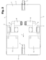
- the illustrated embodiment has a drive with two electric motors 8, each via a gearbox 9 with the associated fixed wheel 2 in the area of Side edges 5 are in operative connection.
- one of two Accumulators 10 existing accumulator arrangement also arranged on the underside of the platform 1.
- the electric motors 8 are shown in the Embodiment with the accumulators 10 via a electronic control arrangement (not shown) connected.
- the control arrangement is with a Actuator 11 ( Figure 1) connected in the Area of the handle 4 is arranged and a joystick 12, over which the speed of the two Electric motors each independently in itself known manner can be controlled.
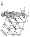
- FIG. 4 In the embodiment shown in Figure 4 is the cleaning cart according to the invention with a Stand device 13 for an operator 14 fitted.
- the stand device 13 is in this embodiment from a standing platform 15 for the operator 14 formed by a suitable coupling device (not shown) to the base 1 of the cleaning cart can be coupled.
- the standing platform 15 is provided with separate wheels 16 equipped, which is the brunt of the weight of the Remove the operator 14 to the ground.
- the arrangement shown in FIG. 4 has the advantage that the cleaning cart relatively easy and fast for the respective operation can be converted.
Landscapes
- Engineering & Computer Science (AREA)
- Chemical & Material Sciences (AREA)
- Combustion & Propulsion (AREA)
- Transportation (AREA)
- Mechanical Engineering (AREA)
- Health & Medical Sciences (AREA)
- Life Sciences & Earth Sciences (AREA)
- Nursing (AREA)
- Biomedical Technology (AREA)
- Animal Behavior & Ethology (AREA)
- General Health & Medical Sciences (AREA)
- Public Health (AREA)
- Veterinary Medicine (AREA)
- Handcart (AREA)
- Cleaning Or Drying Semiconductors (AREA)
- Inorganic Insulating Materials (AREA)
Abstract
Description
- Figur 1
- zeigt in einer perspektivischen Ansicht einen Reinigungswagen mit einer Basis in Form einer Plattform, sowie einem Aufbau zur Aufnahme von Reinigungsutensilien,
- Figur 2
- zeigt die Plattform des Reinigungswagens (ohne Aufbau) in einer Draufsicht, wobei die Elemente und die Anordnung des Antriebes mit punktierten Linien dargestellt sind,
- Figur 3
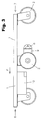
- zeigt eine Seitenansicht der Plattform (ohne Aufbau) aus einer Bodenperspektive und
- Figur 4
- zeigt in einer der Figur 1 entsprechenden perspektivischen Ansicht einen Reinigungswagen mit einer Standeinrichtung für eine Bedienungsperson.
Claims (12)
- Reinigungswagen, mit einer Basis, mindestens drei seitlich oder unter der Basis angeordneten Rädern sowie einem über der Basis angeordneten Aufbau zur Aufnahme von Reinigungsutensilien sowie einer Handhabe,
dadurch gekennzeichnet, dass
auf der Unterseite der Basis (1) mindestens ein Elektromotor (8) mit jeweils in Wirkverbindung stehendem Getriebe (9) angeordnet ist, das auf mindestens eines der Räder (2) wirkt. - Reinigungswagen nach Anspruch 1,
dadurch gekennzeichnet, dass
auf der Unterseite der Basis eine Akkumulatoren-Anordnung (10) angebracht ist. - Reinigungswagen nach Anspruch 1,
dadurch gekennzeichnet, dass
ein mit dem jeweiligen Elektromotor (8) und der Akkumulatoren-Anordnung verbundene Steueranordnung vorgesehen ist, die eine Betätigungseinrichtung (11) im Bereich der Handhabe (4) aufweist. - Reinigungswagen nach einem oder mehreren der vorhergehenden Ansprüche,
dadurch gekennzeichnet, dass
vier unter der Basis (1) angeordnete Räder (2) vorgesehen sind, von denen zwei Räder fest und zwei Räder lenkbar sind. - Reinigungswagen nach Anspruch 4,
dadurch gekennzeichnet, dass
in Fahrtrichtung gesehen die festen Räder (2) etwa in der Mitte des Wagens im Bereich der Seitenränder (5) der Basis (1) und je ein bewegliches Rad (2) jeweils mittig im Bereich des Vorderrandes (6) und des Hinterrandes (7) der Basis (1) angeordnet sind. - Reinigungswagen nach Anspruch 5,
dadurch gekennzeichnet, dass
etwa in der Mitte der Basis (1) zwei Elektromotoren (8) angeordnet sind, die über jeweils ein Getriebe (9) mit jeweils einem der festen Räder (2) in Wirkverbindung stehen. - Reinigungswagen nach Anspruch 5,
dadurch gekennzeichnet, dass
etwa in der Mitte der Basis (1) ein Elektromotor angeordnet ist, der über ein Getriebe mit Differential mit den fest angeordneten Rädern in Wirkverbindung steht. - Reinigungswagen nach Anspruch 3,
dadurch gekennzeichnet, dass
die Handhabe (4) einen Handgriff und die Betätigungseinrichtung (11) einen im Bereich des Handgriffes angeordneter Joystick (12) aufweist. - Reinigungswagen nach einem oder mehreren der vorhergehenden Ansprüche,
dadurch gekennzeichnet, dass
die Akkumulatorenanordnung mit einer im Randbereich der Basis angeordneten Andockleiste ausgestattet ist. - Reinigungswagen nach einem oder mehreren der vorhergehenden Ansprüche,
dadurch gekennzeichnet, dass
die Basis (1) mit einer Standeinrichtung (13) für eine Bedienungsperson (14) ausgestattet ist. - Reinigungswagen nach Anspruch 10,
dadurch gekennzeichnet, dass
die Standeinrichtung (13) in die Basis integriert ist. - Reinigungswagen nach Anspruch 10,
dadurch gekennzeichnet, dass
die Standeinrichtung (13) als an die Basis ankoppelbare Standplattform (15) mit Rädern (16) ausgestaltet ist.
Priority Applications (8)
| Application Number | Priority Date | Filing Date | Title |
|---|---|---|---|
| DK04004139T DK1568581T3 (da) | 2004-02-24 | 2004-02-24 | Rengöringsvogn |
| AT04004139T ATE334035T1 (de) | 2004-02-24 | 2004-02-24 | Reinigungswagen |
| PT04004139T PT1568581E (pt) | 2004-02-24 | 2004-02-24 | Carro de limpeza |
| ES04004139T ES2268509T3 (es) | 2004-02-24 | 2004-02-24 | Carro de limpieza. |
| EP04004139A EP1568581B1 (de) | 2004-02-24 | 2004-02-24 | Reinigungswagen |
| DE502004001038T DE502004001038D1 (de) | 2004-02-24 | 2004-02-24 | Reinigungswagen |
| US10/590,564 US20070289788A1 (en) | 2004-02-24 | 2005-02-21 | Cleaning Cart |
| PCT/EP2005/001776 WO2005080170A2 (de) | 2004-02-24 | 2005-02-21 | Reinigungswagen |
Applications Claiming Priority (1)
| Application Number | Priority Date | Filing Date | Title |
|---|---|---|---|
| EP04004139A EP1568581B1 (de) | 2004-02-24 | 2004-02-24 | Reinigungswagen |
Publications (2)
| Publication Number | Publication Date |
|---|---|
| EP1568581A1 true EP1568581A1 (de) | 2005-08-31 |
| EP1568581B1 EP1568581B1 (de) | 2006-07-26 |
Family
ID=34745868
Family Applications (1)
| Application Number | Title | Priority Date | Filing Date |
|---|---|---|---|
| EP04004139A Expired - Lifetime EP1568581B1 (de) | 2004-02-24 | 2004-02-24 | Reinigungswagen |
Country Status (8)
| Country | Link |
|---|---|
| US (1) | US20070289788A1 (de) |
| EP (1) | EP1568581B1 (de) |
| AT (1) | ATE334035T1 (de) |
| DE (1) | DE502004001038D1 (de) |
| DK (1) | DK1568581T3 (de) |
| ES (1) | ES2268509T3 (de) |
| PT (1) | PT1568581E (de) |
| WO (1) | WO2005080170A2 (de) |
Cited By (6)
| Publication number | Priority date | Publication date | Assignee | Title |
|---|---|---|---|---|
| FR2899550A1 (fr) * | 2006-04-05 | 2007-10-12 | Coutier Ind Sarl Sarl | Chariot d'atelier assiste |
| FR2905263A1 (fr) * | 2006-08-30 | 2008-03-07 | Jacques Cinqualbre | Ensemble mobile multimedias, multiservices et connectable pour le diagnostic, les prescriptions, le suivi medical et les soins infirmiers. |
| EP2039336A3 (de) * | 2007-09-06 | 2009-06-03 | Holdingselskabet MKR Finans ApS | Transportsystem mit Antriebseinheit |
| WO2009068032A3 (en) * | 2007-11-28 | 2009-09-03 | Sophus Berendsen A/S | Combination trolley |
| EP1927525B1 (de) * | 2006-11-30 | 2011-03-02 | Peugeot Citroën Automobiles Sa | Zuführschlitten für Werkstücke zu Produktionslinien |
| RU2455188C1 (ru) * | 2011-02-01 | 2012-07-10 | Государственное образовательное учреждение высшего профессионального образования Московский государственный технический университет "МАМИ" | Транспортное средство с четырьмя опорными колесами, размещенными по ромбической схеме |
Families Citing this family (17)
| Publication number | Priority date | Publication date | Assignee | Title |
|---|---|---|---|---|
| DE102007026566B4 (de) | 2007-06-08 | 2009-02-19 | Vermop Salmon Gmbh | Reinigungswagen |
| WO2010051841A1 (en) * | 2008-11-05 | 2010-05-14 | Ecolab Inc. | Cleaning trolley |
| US8419024B1 (en) | 2009-08-14 | 2013-04-16 | Fernando Arroyo-Ferrer | Cleaning cart |
| USD624269S1 (en) | 2009-11-03 | 2010-09-21 | Ecolab Inc. | Cleaning trolley |
| USD624271S1 (en) | 2009-11-03 | 2010-09-21 | Ecolab Inc. | Cleaning trolley |
| USD624270S1 (en) | 2009-11-03 | 2010-09-21 | Ecolab Inc. | Cleaning trolley |
| USD624724S1 (en) | 2009-11-03 | 2010-09-28 | Ecolab Inc. | Cleaning trolley |
| DE102010015965B4 (de) | 2010-03-15 | 2014-10-30 | Pps Pfennig Reinigungstechnik Gmbh | Reinigungssystemwagen, Satellitenwagen und Verfahren zur zyklischen Wiederherstellung der Einsatzbereitschaft eines Reinigungssystemwagens |
| US20120133110A1 (en) * | 2010-11-30 | 2012-05-31 | Milton Savage | Transportation Storage Device |
| USD734913S1 (en) | 2014-01-03 | 2015-07-21 | Unger Marketing International, Llc | Cleaning cart |
| CN108394480A (zh) * | 2016-08-09 | 2018-08-14 | 孙丽君 | 一种可根据人体站立姿势改变速度和方向的骑站式机动车 |
| CN106983623A (zh) * | 2017-05-09 | 2017-07-28 | 广东科学技术职业学院 | 折叠医用推车 |
| WO2021151587A1 (de) * | 2020-01-28 | 2021-08-05 | Sew-Eurodrive Gmbh & Co. Kg | Mobiles transportsystem |
| USD927818S1 (en) * | 2020-03-08 | 2021-08-10 | 39F Usa Inc | Cart |
| USD918518S1 (en) * | 2020-03-09 | 2021-05-04 | 39F Usa Inc | Cart |
| USD939176S1 (en) | 2020-05-26 | 2021-12-21 | B-O-F Corporation | Cart |
| US11891101B1 (en) * | 2022-11-22 | 2024-02-06 | Ryan Dixson | Motorized utility cart assembly |
Citations (3)
| Publication number | Priority date | Publication date | Assignee | Title |
|---|---|---|---|---|
| WO1995020514A1 (en) * | 1994-01-26 | 1995-08-03 | S. Berendsen Ab | Motor-driven trolley |
| US6000486A (en) * | 1997-04-18 | 1999-12-14 | Medicart, L.L.C. | Apparatus for providing self-propelled motion to medication carts |
| DE10010852A1 (de) * | 2000-03-06 | 2001-09-20 | Vermop Salmon Gmbh | Reinigungswagen |
Family Cites Families (19)
| Publication number | Priority date | Publication date | Assignee | Title |
|---|---|---|---|---|
| US4167983A (en) * | 1975-04-30 | 1979-09-18 | Gould Inc. | Electrically powered service vehicle |
| NO143484C (no) * | 1977-03-14 | 1981-02-25 | Sentralinstituttet For Ind For | Styrbart, motordrevet hjulunderstell. |
| US4529052A (en) * | 1983-08-25 | 1985-07-16 | Mitsubishi Denki Kabushiki Kaisha | Conveyor truck |
| US5064012A (en) * | 1989-10-17 | 1991-11-12 | Martine Losego | System for motorizing a shopping cart or trolly, or the like |
| US5083629A (en) * | 1990-03-12 | 1992-01-28 | Industrial Technology Research Institute | Walking control method for automatic working vehicle |
| US5142910A (en) * | 1990-06-27 | 1992-09-01 | Occupational Orthopaedic Systems, Inc. | Dynamic physiological function testing apparatus and method |
| US5361871A (en) * | 1991-08-20 | 1994-11-08 | Digicomp Research Corporation | Product information system for shoppers |
| US5456332A (en) * | 1992-11-10 | 1995-10-10 | The Board Of Regents Of The University Of Michigan | Multiple-degree-of-freedom vehicle |
| DE4406749C2 (de) * | 1994-03-02 | 1996-08-29 | Henkel Ecolab Gmbh & Co Ohg | Fahrbarer Reinigungswagen mit Anhänger |
| US5445233A (en) * | 1994-08-04 | 1995-08-29 | Fernie; Geoffrey R. | Multi-directional motorized wheelchair |
| JP3032698B2 (ja) * | 1995-04-14 | 2000-04-17 | 松下電工株式会社 | パワーアシスト付運搬車 |
| US5773954A (en) * | 1996-06-26 | 1998-06-30 | Telxon Corporation | Battery charging station for shopping cart mounted portable data collection devices |
| US5842532A (en) * | 1996-09-25 | 1998-12-01 | Fox American Inc. | Personal transport vehicle and method of improving the maneuverability of a vehicle |
| US6218796B1 (en) * | 1998-10-06 | 2001-04-17 | Mobile Design Corporation | Storage cart for rechargeable devices |
| US6443252B1 (en) * | 1999-08-13 | 2002-09-03 | Royce C. Andes | Passenger standing platform on a powered wheelchair |
| US6371228B1 (en) * | 2000-02-12 | 2002-04-16 | Royce H. Husted | Stable powered tricycle with traction steering |
| TW580472B (en) * | 2003-03-27 | 2004-03-21 | Taiwan Bicycle Ind R&D Center | Electromotive skating scooter |
| US7243746B1 (en) * | 2003-06-09 | 2007-07-17 | Abraham Vasant | Recreational electric vehicle |
| US7210545B1 (en) * | 2005-01-07 | 2007-05-01 | Jerry Paul Waid | Motorized beach cart |
-
2004
- 2004-02-24 AT AT04004139T patent/ATE334035T1/de active
- 2004-02-24 ES ES04004139T patent/ES2268509T3/es not_active Expired - Lifetime
- 2004-02-24 EP EP04004139A patent/EP1568581B1/de not_active Expired - Lifetime
- 2004-02-24 DK DK04004139T patent/DK1568581T3/da active
- 2004-02-24 DE DE502004001038T patent/DE502004001038D1/de not_active Expired - Lifetime
- 2004-02-24 PT PT04004139T patent/PT1568581E/pt unknown
-
2005
- 2005-02-21 WO PCT/EP2005/001776 patent/WO2005080170A2/de not_active Ceased
- 2005-02-21 US US10/590,564 patent/US20070289788A1/en not_active Abandoned
Patent Citations (3)
| Publication number | Priority date | Publication date | Assignee | Title |
|---|---|---|---|---|
| WO1995020514A1 (en) * | 1994-01-26 | 1995-08-03 | S. Berendsen Ab | Motor-driven trolley |
| US6000486A (en) * | 1997-04-18 | 1999-12-14 | Medicart, L.L.C. | Apparatus for providing self-propelled motion to medication carts |
| DE10010852A1 (de) * | 2000-03-06 | 2001-09-20 | Vermop Salmon Gmbh | Reinigungswagen |
Cited By (7)
| Publication number | Priority date | Publication date | Assignee | Title |
|---|---|---|---|---|
| FR2899550A1 (fr) * | 2006-04-05 | 2007-10-12 | Coutier Ind Sarl Sarl | Chariot d'atelier assiste |
| FR2905263A1 (fr) * | 2006-08-30 | 2008-03-07 | Jacques Cinqualbre | Ensemble mobile multimedias, multiservices et connectable pour le diagnostic, les prescriptions, le suivi medical et les soins infirmiers. |
| WO2008025901A3 (fr) * | 2006-08-30 | 2008-04-17 | Jacques Cinqualbre | Ensemble mobile multimedias, multiservices et connectable pour le diagnostic, les prescriptions, le suivi medical et les soins infirmiers |
| EP1927525B1 (de) * | 2006-11-30 | 2011-03-02 | Peugeot Citroën Automobiles Sa | Zuführschlitten für Werkstücke zu Produktionslinien |
| EP2039336A3 (de) * | 2007-09-06 | 2009-06-03 | Holdingselskabet MKR Finans ApS | Transportsystem mit Antriebseinheit |
| WO2009068032A3 (en) * | 2007-11-28 | 2009-09-03 | Sophus Berendsen A/S | Combination trolley |
| RU2455188C1 (ru) * | 2011-02-01 | 2012-07-10 | Государственное образовательное учреждение высшего профессионального образования Московский государственный технический университет "МАМИ" | Транспортное средство с четырьмя опорными колесами, размещенными по ромбической схеме |
Also Published As
| Publication number | Publication date |
|---|---|
| DE502004001038D1 (de) | 2006-09-07 |
| WO2005080170A2 (de) | 2005-09-01 |
| PT1568581E (pt) | 2006-11-30 |
| DK1568581T3 (da) | 2006-11-13 |
| WO2005080170A3 (de) | 2005-12-08 |
| EP1568581B1 (de) | 2006-07-26 |
| ATE334035T1 (de) | 2006-08-15 |
| ES2268509T3 (es) | 2007-03-16 |
| US20070289788A1 (en) | 2007-12-20 |
Similar Documents
| Publication | Publication Date | Title |
|---|---|---|
| EP1568581B1 (de) | Reinigungswagen | |
| EP3663488A1 (de) | Parkroboter für ein kraftfahrzeug | |
| WO1998056707A1 (de) | Frontgabelstapler mit schwenkbarer fahrersitzeinheit | |
| WO2012168070A2 (de) | Fahrzeug zur durchführung von arbeiten an einem solarmodul oder solarkollektor | |
| EP1949838B1 (de) | Reinigungsgerät | |
| DE19518116A1 (de) | Flurförderzeug mit einem Fahrerstand | |
| DE102011076517B4 (de) | Handgeführter elektrisch angetriebener Flurförderwagen | |
| DE69806316T2 (de) | Wagen mit Hubmast, geeignet zur Montage an das Ende eines Transportfahrzeugs | |
| DE102020104790A1 (de) | Fahrerloses Transportfahrzeug | |
| EP1394098A2 (de) | Schubmaststapler | |
| DE4220456C1 (de) | Schienenschleifmaschine | |
| DE69300582T2 (de) | Elektrischer Hubwagen mit einem teleskopischen Arm. | |
| DE102013001766B4 (de) | Transportwagen mit selbstaufladendem Rangierantrieb für den freien Transport von Bauteilen in Fabriken | |
| DE2020588A1 (de) | Manipulator zur Bewegung von Lasten und Geraeten,insbesondere Hubschraubern,in einer Ebene | |
| DE4440202A1 (de) | Reinigungs- und Trockenmaschine zum Reinigen von Böden | |
| EP3412620B1 (de) | Aufbaukran und aufbaukransystem | |
| EP0221257B1 (de) | Flurförderwagen mit integrierter Entpannungsvorrichtung | |
| WO2019086124A1 (de) | Transportsystem und verfahren zum betreiben eines derartigen transportsystems | |
| DE8534229U1 (de) | Selbstfahrende Hebebühne | |
| CH392289A (de) | Fahrzeug | |
| DE19505456A1 (de) | Antriebsteil für ein Flurförderzeug | |
| DE4225492A1 (de) | Golf-Caddiewagen mit integriertem elektrischem Antrieb | |
| WO1994005198A1 (de) | Bodenbearbeitungsmaschine | |
| DE9006521U1 (de) | Selbstfahrendes Trägerfahrzeug für Hubarbeitsbühnen | |
| DE102007063907B3 (de) | Omnidirektionales Fahrmodul und omnidirektionales Fahrzeug |
Legal Events
| Date | Code | Title | Description |
|---|---|---|---|
| PUAI | Public reference made under article 153(3) epc to a published international application that has entered the european phase |
Free format text: ORIGINAL CODE: 0009012 |
|
| 17P | Request for examination filed |
Effective date: 20040224 |
|
| AK | Designated contracting states |
Kind code of ref document: A1 Designated state(s): AT BE BG CH CY CZ DE DK EE ES FI FR GB GR HU IE IT LI LU MC NL PT RO SE SI SK TR |
|
| AX | Request for extension of the european patent |
Extension state: AL LT LV MK |
|
| GRAP | Despatch of communication of intention to grant a patent |
Free format text: ORIGINAL CODE: EPIDOSNIGR1 |
|
| AKX | Designation fees paid |
Designated state(s): AT BE BG CH CY CZ DE DK EE ES FI FR GB GR HU IE IT LI LU MC NL PT RO SE SI SK TR |
|
| GRAS | Grant fee paid |
Free format text: ORIGINAL CODE: EPIDOSNIGR3 |
|
| GRAA | (expected) grant |
Free format text: ORIGINAL CODE: 0009210 |
|
| AK | Designated contracting states |
Kind code of ref document: B1 Designated state(s): AT BE BG CH CY CZ DE DK EE ES FI FR GB GR HU IE IT LI LU MC NL PT RO SE SI SK TR |
|
| PG25 | Lapsed in a contracting state [announced via postgrant information from national office to epo] |
Ref country code: IT Free format text: LAPSE BECAUSE OF FAILURE TO SUBMIT A TRANSLATION OF THE DESCRIPTION OR TO PAY THE FEE WITHIN THE PRESCRIBED TIME-LIMIT;WARNING: LAPSES OF ITALIAN PATENTS WITH EFFECTIVE DATE BEFORE 2007 MAY HAVE OCCURRED AT ANY TIME BEFORE 2007. THE CORRECT EFFECTIVE DATE MAY BE DIFFERENT FROM THE ONE RECORDED. Effective date: 20060726 Ref country code: SI Free format text: LAPSE BECAUSE OF FAILURE TO SUBMIT A TRANSLATION OF THE DESCRIPTION OR TO PAY THE FEE WITHIN THE PRESCRIBED TIME-LIMIT Effective date: 20060726 Ref country code: RO Free format text: LAPSE BECAUSE OF FAILURE TO SUBMIT A TRANSLATION OF THE DESCRIPTION OR TO PAY THE FEE WITHIN THE PRESCRIBED TIME-LIMIT Effective date: 20060726 |
|
| REG | Reference to a national code |
Ref country code: GB Ref legal event code: FG4D Free format text: NOT ENGLISH |
|
| REG | Reference to a national code |
Ref country code: CH Ref legal event code: EP |
|
| REG | Reference to a national code |
Ref country code: IE Ref legal event code: FG4D Free format text: LANGUAGE OF EP DOCUMENT: GERMAN |
|
| REF | Corresponds to: |
Ref document number: 502004001038 Country of ref document: DE Date of ref document: 20060907 Kind code of ref document: P |
|
| REG | Reference to a national code |
Ref country code: SE Ref legal event code: TRGR |
|
| GBT | Gb: translation of ep patent filed (gb section 77(6)(a)/1977) |
Effective date: 20061004 |
|
| PG25 | Lapsed in a contracting state [announced via postgrant information from national office to epo] |
Ref country code: BG Free format text: LAPSE BECAUSE OF FAILURE TO SUBMIT A TRANSLATION OF THE DESCRIPTION OR TO PAY THE FEE WITHIN THE PRESCRIBED TIME-LIMIT Effective date: 20061026 |
|
| REG | Reference to a national code |
Ref country code: DK Ref legal event code: T3 |
|
| REG | Reference to a national code |
Ref country code: CH Ref legal event code: NV Representative=s name: NOVAGRAAF INTERNATIONAL SA |
|
| REG | Reference to a national code |
Ref country code: GR Ref legal event code: EP Ref document number: 20060403573 Country of ref document: GR |
|
| REG | Reference to a national code |
Ref country code: PT Ref legal event code: SC4A Free format text: AVAILABILITY OF NATIONAL TRANSLATION Effective date: 20061003 |
|
| ET | Fr: translation filed | ||
| PG25 | Lapsed in a contracting state [announced via postgrant information from national office to epo] |
Ref country code: MC Free format text: LAPSE BECAUSE OF NON-PAYMENT OF DUE FEES Effective date: 20070228 |
|
| REG | Reference to a national code |
Ref country code: HU Ref legal event code: AG4A Ref document number: E001034 Country of ref document: HU |
|
| REG | Reference to a national code |
Ref country code: ES Ref legal event code: FG2A Ref document number: 2268509 Country of ref document: ES Kind code of ref document: T3 |
|
| PLBE | No opposition filed within time limit |
Free format text: ORIGINAL CODE: 0009261 |
|
| STAA | Information on the status of an ep patent application or granted ep patent |
Free format text: STATUS: NO OPPOSITION FILED WITHIN TIME LIMIT |
|
| 26N | No opposition filed |
Effective date: 20070427 |
|
| PG25 | Lapsed in a contracting state [announced via postgrant information from national office to epo] |
Ref country code: EE Free format text: LAPSE BECAUSE OF FAILURE TO SUBMIT A TRANSLATION OF THE DESCRIPTION OR TO PAY THE FEE WITHIN THE PRESCRIBED TIME-LIMIT Effective date: 20060726 |
|
| PG25 | Lapsed in a contracting state [announced via postgrant information from national office to epo] |
Ref country code: LU Free format text: LAPSE BECAUSE OF NON-PAYMENT OF DUE FEES Effective date: 20070224 Ref country code: CY Free format text: LAPSE BECAUSE OF FAILURE TO SUBMIT A TRANSLATION OF THE DESCRIPTION OR TO PAY THE FEE WITHIN THE PRESCRIBED TIME-LIMIT Effective date: 20060726 |
|
| PGFP | Annual fee paid to national office [announced via postgrant information from national office to epo] |
Ref country code: IE Payment date: 20101230 Year of fee payment: 8 |
|
| PGFP | Annual fee paid to national office [announced via postgrant information from national office to epo] |
Ref country code: SE Payment date: 20110215 Year of fee payment: 8 Ref country code: TR Payment date: 20110214 Year of fee payment: 8 Ref country code: SK Payment date: 20110112 Year of fee payment: 8 Ref country code: PT Payment date: 20110222 Year of fee payment: 8 Ref country code: IT Payment date: 20110214 Year of fee payment: 8 Ref country code: FI Payment date: 20110218 Year of fee payment: 8 Ref country code: NL Payment date: 20110216 Year of fee payment: 8 |
|
| REG | Reference to a national code |
Ref country code: CH Ref legal event code: PFA Owner name: VERMOP SALMON GMBH Free format text: VERMOP SALMON GMBH#KIESWEG 4-6#D-97877 WERTHEIM (DE) -TRANSFER TO- VERMOP SALMON GMBH#KIESWEG 4-6#D-97877 WERTHEIM (DE) |
|
| PGFP | Annual fee paid to national office [announced via postgrant information from national office to epo] |
Ref country code: GR Payment date: 20110224 Year of fee payment: 8 |
|
| PGFP | Annual fee paid to national office [announced via postgrant information from national office to epo] |
Ref country code: HU Payment date: 20110422 Year of fee payment: 8 |
|
| PGFP | Annual fee paid to national office [announced via postgrant information from national office to epo] |
Ref country code: CZ Payment date: 20120410 Year of fee payment: 9 |
|
| REG | Reference to a national code |
Ref country code: PT Ref legal event code: MM4A Free format text: LAPSE DUE TO NON-PAYMENT OF FEES Effective date: 20120824 |
|
| REG | Reference to a national code |
Ref country code: NL Ref legal event code: V1 Effective date: 20120901 |
|
| REG | Reference to a national code |
Ref country code: GR Ref legal event code: ML Ref document number: 20060403573 Country of ref document: GR Effective date: 20120905 |
|
| PG25 | Lapsed in a contracting state [announced via postgrant information from national office to epo] |
Ref country code: FI Free format text: LAPSE BECAUSE OF NON-PAYMENT OF DUE FEES Effective date: 20120224 Ref country code: SE Free format text: LAPSE BECAUSE OF NON-PAYMENT OF DUE FEES Effective date: 20120225 |
|
| REG | Reference to a national code |
Ref country code: SK Ref legal event code: MM4A Ref document number: E 1092 Country of ref document: SK Effective date: 20120224 |
|
| REG | Reference to a national code |
Ref country code: IE Ref legal event code: MM4A |
|
| PG25 | Lapsed in a contracting state [announced via postgrant information from national office to epo] |
Ref country code: PT Free format text: LAPSE BECAUSE OF NON-PAYMENT OF DUE FEES Effective date: 20120824 Ref country code: HU Free format text: LAPSE BECAUSE OF NON-PAYMENT OF DUE FEES Effective date: 20120225 Ref country code: GR Free format text: LAPSE BECAUSE OF NON-PAYMENT OF DUE FEES Effective date: 20120905 Ref country code: SK Free format text: LAPSE BECAUSE OF NON-PAYMENT OF DUE FEES Effective date: 20120224 |
|
| PG25 | Lapsed in a contracting state [announced via postgrant information from national office to epo] |
Ref country code: IE Free format text: LAPSE BECAUSE OF NON-PAYMENT OF DUE FEES Effective date: 20120224 Ref country code: NL Free format text: LAPSE BECAUSE OF NON-PAYMENT OF DUE FEES Effective date: 20120901 |
|
| PG25 | Lapsed in a contracting state [announced via postgrant information from national office to epo] |
Ref country code: CZ Free format text: LAPSE BECAUSE OF NON-PAYMENT OF DUE FEES Effective date: 20130224 |
|
| PGFP | Annual fee paid to national office [announced via postgrant information from national office to epo] |
Ref country code: ES Payment date: 20130806 Year of fee payment: 10 Ref country code: CH Payment date: 20130814 Year of fee payment: 10 |
|
| PG25 | Lapsed in a contracting state [announced via postgrant information from national office to epo] |
Ref country code: IT Free format text: LAPSE BECAUSE OF NON-PAYMENT OF DUE FEES Effective date: 20120224 |
|
| PGFP | Annual fee paid to national office [announced via postgrant information from national office to epo] |
Ref country code: BE Payment date: 20130807 Year of fee payment: 10 |
|
| PG25 | Lapsed in a contracting state [announced via postgrant information from national office to epo] |
Ref country code: TR Free format text: LAPSE BECAUSE OF NON-PAYMENT OF DUE FEES Effective date: 20120224 |
|
| PGFP | Annual fee paid to national office [announced via postgrant information from national office to epo] |
Ref country code: DK Payment date: 20140227 Year of fee payment: 11 |
|
| PGFP | Annual fee paid to national office [announced via postgrant information from national office to epo] |
Ref country code: AT Payment date: 20140226 Year of fee payment: 11 |
|
| BERE | Be: lapsed |
Owner name: *VERMOP SALMON G.M.B.H. Effective date: 20140228 |
|
| REG | Reference to a national code |
Ref country code: CH Ref legal event code: PL |
|
| PG25 | Lapsed in a contracting state [announced via postgrant information from national office to epo] |
Ref country code: CH Free format text: LAPSE BECAUSE OF NON-PAYMENT OF DUE FEES Effective date: 20140228 Ref country code: LI Free format text: LAPSE BECAUSE OF NON-PAYMENT OF DUE FEES Effective date: 20140228 |
|
| PG25 | Lapsed in a contracting state [announced via postgrant information from national office to epo] |
Ref country code: BE Free format text: LAPSE BECAUSE OF NON-PAYMENT OF DUE FEES Effective date: 20140228 |
|
| REG | Reference to a national code |
Ref country code: DK Ref legal event code: EBP Effective date: 20150228 |
|
| REG | Reference to a national code |
Ref country code: AT Ref legal event code: MM01 Ref document number: 334035 Country of ref document: AT Kind code of ref document: T Effective date: 20150224 |
|
| PG25 | Lapsed in a contracting state [announced via postgrant information from national office to epo] |
Ref country code: AT Free format text: LAPSE BECAUSE OF NON-PAYMENT OF DUE FEES Effective date: 20150224 |
|
| PG25 | Lapsed in a contracting state [announced via postgrant information from national office to epo] |
Ref country code: DK Free format text: LAPSE BECAUSE OF NON-PAYMENT OF DUE FEES Effective date: 20150228 |
|
| PG25 | Lapsed in a contracting state [announced via postgrant information from national office to epo] |
Ref country code: ES Free format text: LAPSE BECAUSE OF NON-PAYMENT OF DUE FEES Effective date: 20140225 |
|
| REG | Reference to a national code |
Ref country code: FR Ref legal event code: PLFP Year of fee payment: 13 |
|
| REG | Reference to a national code |
Ref country code: FR Ref legal event code: PLFP Year of fee payment: 14 |
|
| REG | Reference to a national code |
Ref country code: FR Ref legal event code: PLFP Year of fee payment: 15 |
|
| PGFP | Annual fee paid to national office [announced via postgrant information from national office to epo] |
Ref country code: FR Payment date: 20230221 Year of fee payment: 20 |
|
| PGFP | Annual fee paid to national office [announced via postgrant information from national office to epo] |
Ref country code: GB Payment date: 20230208 Year of fee payment: 20 Ref country code: DE Payment date: 20220621 Year of fee payment: 20 |
|
| P01 | Opt-out of the competence of the unified patent court (upc) registered |
Effective date: 20230508 |
|
| REG | Reference to a national code |
Ref country code: DE Ref legal event code: R071 Ref document number: 502004001038 Country of ref document: DE |
|
| REG | Reference to a national code |
Ref country code: GB Ref legal event code: PE20 Expiry date: 20240223 |
|
| PG25 | Lapsed in a contracting state [announced via postgrant information from national office to epo] |
Ref country code: GB Free format text: LAPSE BECAUSE OF EXPIRATION OF PROTECTION Effective date: 20240223 |