EP1568521A2 - Stabilisatorsteuergerät - Google Patents
Stabilisatorsteuergerät Download PDFInfo
- Publication number
- EP1568521A2 EP1568521A2 EP05004072A EP05004072A EP1568521A2 EP 1568521 A2 EP1568521 A2 EP 1568521A2 EP 05004072 A EP05004072 A EP 05004072A EP 05004072 A EP05004072 A EP 05004072A EP 1568521 A2 EP1568521 A2 EP 1568521A2
- Authority
- EP
- European Patent Office
- Prior art keywords
- lateral acceleration
- vehicle
- calculated
- stabilizer
- actual lateral
- Prior art date
- Legal status (The legal status is an assumption and is not a legal conclusion. Google has not performed a legal analysis and makes no representation as to the accuracy of the status listed.)
- Granted
Links
Images


Classifications
-
- B—PERFORMING OPERATIONS; TRANSPORTING
- B60—VEHICLES IN GENERAL
- B60G—VEHICLE SUSPENSION ARRANGEMENTS
- B60G21/00—Interconnection systems for two or more resiliently-suspended wheels, e.g. for stabilising a vehicle body with respect to acceleration, deceleration or centrifugal forces
- B60G21/02—Interconnection systems for two or more resiliently-suspended wheels, e.g. for stabilising a vehicle body with respect to acceleration, deceleration or centrifugal forces permanently interconnected
- B60G21/04—Interconnection systems for two or more resiliently-suspended wheels, e.g. for stabilising a vehicle body with respect to acceleration, deceleration or centrifugal forces permanently interconnected mechanically
- B60G21/05—Interconnection systems for two or more resiliently-suspended wheels, e.g. for stabilising a vehicle body with respect to acceleration, deceleration or centrifugal forces permanently interconnected mechanically between wheels on the same axle but on different sides of the vehicle, i.e. the left and right wheel suspensions being interconnected
- B60G21/055—Stabiliser bars
- B60G21/0551—Mounting means therefor
- B60G21/0553—Mounting means therefor adjustable
- B60G21/0555—Mounting means therefor adjustable including an actuator inducing vehicle roll
-
- B—PERFORMING OPERATIONS; TRANSPORTING
- B60—VEHICLES IN GENERAL
- B60G—VEHICLE SUSPENSION ARRANGEMENTS
- B60G17/00—Resilient suspensions having means for adjusting the spring or vibration-damper characteristics, for regulating the distance between a supporting surface and a sprung part of vehicle or for locking suspension during use to meet varying vehicular or surface conditions, e.g. due to speed or load
- B60G17/015—Resilient suspensions having means for adjusting the spring or vibration-damper characteristics, for regulating the distance between a supporting surface and a sprung part of vehicle or for locking suspension during use to meet varying vehicular or surface conditions, e.g. due to speed or load the regulating means comprising electric or electronic elements
- B60G17/016—Resilient suspensions having means for adjusting the spring or vibration-damper characteristics, for regulating the distance between a supporting surface and a sprung part of vehicle or for locking suspension during use to meet varying vehicular or surface conditions, e.g. due to speed or load the regulating means comprising electric or electronic elements characterised by their responsiveness, when the vehicle is travelling, to specific motion, a specific condition, or driver input
- B60G17/0162—Resilient suspensions having means for adjusting the spring or vibration-damper characteristics, for regulating the distance between a supporting surface and a sprung part of vehicle or for locking suspension during use to meet varying vehicular or surface conditions, e.g. due to speed or load the regulating means comprising electric or electronic elements characterised by their responsiveness, when the vehicle is travelling, to specific motion, a specific condition, or driver input mainly during a motion involving steering operation, e.g. cornering, overtaking
-
- B—PERFORMING OPERATIONS; TRANSPORTING
- B60—VEHICLES IN GENERAL
- B60G—VEHICLE SUSPENSION ARRANGEMENTS
- B60G17/00—Resilient suspensions having means for adjusting the spring or vibration-damper characteristics, for regulating the distance between a supporting surface and a sprung part of vehicle or for locking suspension during use to meet varying vehicular or surface conditions, e.g. due to speed or load
- B60G17/015—Resilient suspensions having means for adjusting the spring or vibration-damper characteristics, for regulating the distance between a supporting surface and a sprung part of vehicle or for locking suspension during use to meet varying vehicular or surface conditions, e.g. due to speed or load the regulating means comprising electric or electronic elements
- B60G17/018—Resilient suspensions having means for adjusting the spring or vibration-damper characteristics, for regulating the distance between a supporting surface and a sprung part of vehicle or for locking suspension during use to meet varying vehicular or surface conditions, e.g. due to speed or load the regulating means comprising electric or electronic elements characterised by the use of a specific signal treatment or control method
- B60G17/0182—Resilient suspensions having means for adjusting the spring or vibration-damper characteristics, for regulating the distance between a supporting surface and a sprung part of vehicle or for locking suspension during use to meet varying vehicular or surface conditions, e.g. due to speed or load the regulating means comprising electric or electronic elements characterised by the use of a specific signal treatment or control method involving parameter estimation, e.g. observer, Kalman filter
-
- B—PERFORMING OPERATIONS; TRANSPORTING
- B60—VEHICLES IN GENERAL
- B60G—VEHICLE SUSPENSION ARRANGEMENTS
- B60G17/00—Resilient suspensions having means for adjusting the spring or vibration-damper characteristics, for regulating the distance between a supporting surface and a sprung part of vehicle or for locking suspension during use to meet varying vehicular or surface conditions, e.g. due to speed or load
- B60G17/015—Resilient suspensions having means for adjusting the spring or vibration-damper characteristics, for regulating the distance between a supporting surface and a sprung part of vehicle or for locking suspension during use to meet varying vehicular or surface conditions, e.g. due to speed or load the regulating means comprising electric or electronic elements
- B60G17/019—Resilient suspensions having means for adjusting the spring or vibration-damper characteristics, for regulating the distance between a supporting surface and a sprung part of vehicle or for locking suspension during use to meet varying vehicular or surface conditions, e.g. due to speed or load the regulating means comprising electric or electronic elements characterised by the type of sensor or the arrangement thereof
- B60G17/01908—Acceleration or inclination sensors
-
- B—PERFORMING OPERATIONS; TRANSPORTING
- B60—VEHICLES IN GENERAL
- B60G—VEHICLE SUSPENSION ARRANGEMENTS
- B60G2400/00—Indexing codes relating to detected, measured or calculated conditions or factors
- B60G2400/10—Acceleration; Deceleration
- B60G2400/104—Acceleration; Deceleration lateral or transversal with regard to vehicle
-
- B—PERFORMING OPERATIONS; TRANSPORTING
- B60—VEHICLES IN GENERAL
- B60G—VEHICLE SUSPENSION ARRANGEMENTS
- B60G2400/00—Indexing codes relating to detected, measured or calculated conditions or factors
- B60G2400/20—Speed
- B60G2400/204—Vehicle speed
-
- B—PERFORMING OPERATIONS; TRANSPORTING
- B60—VEHICLES IN GENERAL
- B60G—VEHICLE SUSPENSION ARRANGEMENTS
- B60G2400/00—Indexing codes relating to detected, measured or calculated conditions or factors
- B60G2400/40—Steering conditions
- B60G2400/41—Steering angle
-
- B—PERFORMING OPERATIONS; TRANSPORTING
- B60—VEHICLES IN GENERAL
- B60G—VEHICLE SUSPENSION ARRANGEMENTS
- B60G2400/00—Indexing codes relating to detected, measured or calculated conditions or factors
- B60G2400/60—Load
- B60G2400/61—Load distribution
-
- B—PERFORMING OPERATIONS; TRANSPORTING
- B60—VEHICLES IN GENERAL
- B60G—VEHICLE SUSPENSION ARRANGEMENTS
- B60G2400/00—Indexing codes relating to detected, measured or calculated conditions or factors
- B60G2400/80—Exterior conditions
- B60G2400/82—Ground surface
- B60G2400/821—Uneven, rough road sensing affecting vehicle body vibration
-
- B—PERFORMING OPERATIONS; TRANSPORTING
- B60—VEHICLES IN GENERAL
- B60G—VEHICLE SUSPENSION ARRANGEMENTS
- B60G2400/00—Indexing codes relating to detected, measured or calculated conditions or factors
- B60G2400/80—Exterior conditions
- B60G2400/82—Ground surface
- B60G2400/822—Road friction coefficient determination affecting wheel traction
-
- B—PERFORMING OPERATIONS; TRANSPORTING
- B60—VEHICLES IN GENERAL
- B60G—VEHICLE SUSPENSION ARRANGEMENTS
- B60G2600/00—Indexing codes relating to particular elements, systems or processes used on suspension systems or suspension control systems
- B60G2600/17—Proportional control, i.e. gain control
-
- B—PERFORMING OPERATIONS; TRANSPORTING
- B60—VEHICLES IN GENERAL
- B60G—VEHICLE SUSPENSION ARRANGEMENTS
- B60G2600/00—Indexing codes relating to particular elements, systems or processes used on suspension systems or suspension control systems
- B60G2600/18—Automatic control means
- B60G2600/187—Digital Controller Details and Signal Treatment
- B60G2600/1877—Adaptive Control
-
- B—PERFORMING OPERATIONS; TRANSPORTING
- B60—VEHICLES IN GENERAL
- B60G—VEHICLE SUSPENSION ARRANGEMENTS
- B60G2800/00—Indexing codes relating to the type of movement or to the condition of the vehicle and to the end result to be achieved by the control action
- B60G2800/01—Attitude or posture control
- B60G2800/012—Rolling condition
- B60G2800/0122—Roll rigidity ratio; Warping
-
- B—PERFORMING OPERATIONS; TRANSPORTING
- B60—VEHICLES IN GENERAL
- B60G—VEHICLE SUSPENSION ARRANGEMENTS
- B60G2800/00—Indexing codes relating to the type of movement or to the condition of the vehicle and to the end result to be achieved by the control action
- B60G2800/24—Steering, cornering
-
- B—PERFORMING OPERATIONS; TRANSPORTING
- B60—VEHICLES IN GENERAL
- B60G—VEHICLE SUSPENSION ARRANGEMENTS
- B60G2800/00—Indexing codes relating to the type of movement or to the condition of the vehicle and to the end result to be achieved by the control action
- B60G2800/70—Estimating or calculating vehicle parameters or state variables
- B60G2800/702—Improving accuracy of a sensor signal
Definitions
- the present invention relates to a stabilizer control apparatus for a vehicle, and more particularly to an apparatus for controlling a torsional rigidity of a stabilizer disposed between a right wheel and a left wheel.
- a stabilizer control apparatus for a vehicle for applying an appropriate roll moment to a vehicle by means of a stabilizer, while the vehicle is performing a turning operation, to reduce or restrict a rolling motion of the vehicle body.
- Japanese Patent Laid-open Publication No.2000-71739 discloses an apparatus for controlling efficiency of a stabilizer to vary an apparent torsional rigidity of the stabilizer by driving and controlling an actuator in response to output of means for detecting a turning level of a vehicle, e.g., a lateral acceleration sensor.
- the actuator is actuated to control a varying position of the vehicle, so as to provide a property attaching importance to ride comfort in a range of relatively small turning operation, and it is actuated to control the varying position of the vehicle, so as to provide a property attaching importance to stability, with an inherent rigidity of the stabilizer produced by limiting the movement of the actuator with a small movable range, when the turning operation is increased.
- Japanese Patent Laid-open Publication No.9-20223 there is disclosed a method for determining a rough road, by calculating a wheel acceleration on the basis of a wheel speed, and obtaining its high-frequency component through a high-pass filter, to calculate a dispersion of the wheel acceleration, on the basis of which the rough road is determined.
- Japanese Patent Laid-open Publication No.2001-63544 discloses a method for determining a rough road according to a result of F-study through a dispersion of differentiated value of output from an acceleration sensor obtained when a vehicle is running on a reference flat road surface at a small steering angle, and a dispersion of differentiated value of output from the acceleration sensor obtained when the vehicle is running on the present road surface at the small steering angle. Furthermore, in Japanese Patent Laid-open Publication No.9-193776, as to factors for use in a vehicle stability control, there are disclosed spinning value indicative of spinning state variable and drift-out value indicative of drift-out state variable.
- the lateral acceleration indicative of the turning level is not caused only by the turning operation of the vehicle, but it may be caused by a rough surface of a road, on which the vehicle is running.
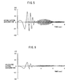
- the lateral acceleration may be caused by the rough surface of the road, even if the vehicle is moving straight, as shown in FIG.5, in the case where the vehicle is running on such a road surface called as a roll-sweep that the road has a property of opposite phases at its right side and left side of a moving direction of the vehicle, with frequency and amplitude of the property being varied as time passes.
- the stabilizer control apparatus is provided for controlling to restrain a roll angle of vehicle body caused at the time of turning operation of the vehicle. This can be achieved by controlling and actuating a stabilizer actuator to increase a torsional rigidity of a stabilizer in response to a lateral acceleration indicative of the turning operation.
- a stabilizer actuator to increase a torsional rigidity of a stabilizer in response to a lateral acceleration indicative of the turning operation.
- the stabilizer is controlled to increase its torsional rigidity in response to variation of the lateral acceleration.
- the stabilizer control will be made so as to act against change in rolling motion caused only by the rough road surface, while the vehicle is not in its turning operation, which control might result in deteriorating the ride comfort.
- the stabilizer control apparatus for controlling a torsional rigidity of a stabilizer disposed between a right wheel and a left wheel of a vehicle to control a rolling motion of a vehicle body actively in response to turning operation of the vehicle.
- the apparatus includes an actual lateral acceleration obtaining device for obtaining an information indicative of actual lateral acceleration of the vehicle, a calculated lateral acceleration obtaining device for obtaining an information indicative of calculated lateral acceleration of the vehicle, in response to steering operation of the vehicle, and a controller for setting influence amount caused by the calculated lateral acceleration obtaining device to be greater than influence amount caused by the actual lateral acceleration obtaining device, when the vehicle is moving straight.
- the controller is adapted to set the influence amount caused by the actual lateral acceleration obtaining device to be increased, with the turning operation of the vehicle being increased, to actively control the rolling motion of the vehicle body.
- the actual lateral acceleration obtaining device is adapted to obtain the information indicative of actual lateral acceleration, by detecting or calculating the same.
- the stabilizer control apparatus may include an actual lateral acceleration detection device for detecting an actual lateral acceleration actually acting on the vehicle, a vehicle speed detection device for detecting a speed of the vehicle, a steering angle detection device for detecting a steering angle provided in response to operation of a steering wheel of the vehicle, and an acceleration calculation device for obtaining a calculated lateral acceleration, on the basis of the vehicle speed detected by the vehicle speed detection device and the steering angle detected by the steering angle detection device.
- the apparatus further includes an externally applied force determination device for determining externally applied force for controlling the torsional rigidity of the stabilizer, on the basis of the calculated lateral acceleration obtained by the lateral acceleration calculation device and the actual lateral acceleration detected by the actual lateral acceleration detection device, a turning factor setting device for setting a turning factor indicative of turning operation of the vehicle, and a modification device for setting a control gain for the calculated lateral acceleration to be larger than a control gain relative to the actual lateral acceleration, when the turning factor set by the turning factor setting device is relatively small.
- the modification device is adapted to modify the control gain relative to the calculated lateral acceleration to be decreased, or modify the control gain relative to the actual lateral acceleration to be increased, when the turning factor set by the turning factor setting device is relatively large.
- the turning factor setting device is adapted to set the turning factor on the basis of at least one of a yaw rate which is detected by a yaw rate detection device, the calculated lateral acceleration, the actual lateral acceleration, and the steering angle.
- FIG.1 there is schematically illustrated a vehicle with a stabilizer control apparatus according to an embodiment of the present invention.
- a front stabilizer SBf and a rear stabilizer SBr are disposed to act as a torsion spring when a rolling motion is applied to a vehicle body (not shown).
- the front stabilizer SBf and rear stabilizer SBr are actuated by stabilizer actuators FT and RT, respectively, to control each torsional rigidity, so as to restrain a roll angle of vehicle body resulted from the rolling motion of the vehicle body.
- the stabilizer actuators FT and RT are controlled by a stabilizer control unit ECU1 provided in an electronic controller ECU.
- a wheel speed sensor WSxx which is connected to the electronic controller ECU, and by which a signal having pulses proportional to a rotational speed of each wheel, i.e., a wheel speed signal is fed to the electronic controller ECU.
- "xx" designates each wheel, i.e., "fr” designates the wheel at the front right side as viewed from the position of a driver's seat, "fl” designates the wheel at the front left side, “rr” designates the wheel at the rear right side, and “rl” designates the wheel at the rear left side.
- a steering angle sensor SA for detecting a steering angle (handle angle) ( ⁇ f) provided in response to operation of a steering wheel SW, a longitudinal acceleration sensor XG for detecting a vehicle longitudinal acceleration (Gx), a lateral acceleration sensor YG for detecting an actual lateral acceleration (Gya) of a vehicle, a yaw rate sensor YR for detecting a yaw rate (Yr) of the vehicle, and so on, which are electrically connected to the electronic controller ECU.
- the electronic controller ECU includes a brake control unit ECU2, steering control unit ECU3 and the like, which are connected to a communication unit (not shown) having a CPU, ROM and RAM for communication, through a communication bus. Therefore, the information for each control system can be fed from other control systems.
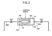
- the stabilizer actuator FT includes a front stabilizer SBf, which is provided with a pair of (right and left) stabilizer bars SBfr and SBfl, one end of each bar is connected to a right or left wheel (not shown), and the other end of one bar is connected to a rotor RO of an electric motor M through a speed reducing mechanism (or, speed reducer) RD, and the other end of the other one bar is connected to a stator SR of the motor M.
- the stabilizer bars SBfr and SBfl are mounted on a vehicle body (not shown) by holding members HLfr and HLfl.
- the stabilizer actuator RT is constituted in the same manner as described above.
- a rotational angle sensor RS is disposed in the stabilizer actuator FT, to act as a rotational angle detection device for detecting a rotational angle of the motor M.
- a pump actuated by a motor or an engine may be used, to control hydraulic pressure fed to actuate the stabilizer actuator.
- the active roll restraining control wherein the information including the steering angle (handle angle) ( ⁇ f) is detected by a vehicle driver operation detection device M11, and wherein vehicle motion variable including the vehicle speed, lateral acceleration and yaw rate is detected by a vehicle running condition detection device M12.
- vehicle motion variable including the vehicle speed, lateral acceleration and yaw rate
- a desired value of vehicle active roll moment is calculated at a block M13 to achieve a desirable rolling performance of the vehicle.
- a vehicle steering performance (oversteer or understeer) is determined on the basis of the steering operation of the vehicle driver and the vehicle motion variable.
- the desired value of the front and rear roll rigidity ratio is calculated at a block M15 on the basis of the calculated steering performance and vehicle motion variable. Based on the desired values of vehicle active roll moment and the roll rigidity ratios, the desired values of active roll moment for the front and rear wheels are calculated at a block M16. Then, on the basis of these desired values, the stabilizer actuators FT and RT are controlled at an actuator servo block M17.
- FIG.4 shows an example of the embodiment as shown in FIG.3, wherein a desired value (Rmv) of vehicle active roll moment for restraining the rolling motion of the vehicle as a whole is calculated at the block M13, on the basis of the actual lateral acceleration (Gya) detected by the lateral acceleration sensor YG, the variation of actual lateral acceleration (dGya) obtained by differentiating the actual lateral acceleration (Gya), the calculated (or, estimated) lateral acceleration (Gye) calculated by the steering angle (handle angle) ( ⁇ f) and vehicle speed (Vx), and the variation of the calculated lateral acceleration (dGye) obtained by differentiating the calculated lateral acceleration (Gye).
- a desired value (Rmv) of vehicle active roll moment for restraining the rolling motion of the vehicle as a whole is calculated at the block M13, on the basis of the actual lateral acceleration (Gya) detected by the lateral acceleration sensor YG, the variation of actual lateral acceleration (dGya) obtained by differenti
- Gye (Vx 2 ⁇ ⁇ f) / ⁇ L ⁇ N ⁇ (1+Kh ⁇ Vx 2 ) ⁇
- L is a wheel base
- N is a steering gear ratio
- Kh is a stability factor
- the actual lateral acceleration (Gya) is influenced by the irregularity of road surface, and the actual lateral acceleration (Gya) is delayed, because it is obtained as a result of steering operation.
- the actual lateral acceleration (Gya) is of a value for surely reflecting the road surface condition, e.g., coefficient of friction of the road surface.
- the calculated lateral acceleration (Gye) is not influenced by the irregularity of road surface, and obtained by the steering inputs, i.e., steering angle ( ⁇ f) and vehicle speed (Vx), so that it will be hardly delayed.
- the calculated lateral acceleration (Gye) is not of a value for reflecting the road surface condition (e.g., coefficient of friction), so that its accuracy will be lowered, if the vehicle is turning in such a state as exceeding a frictional limit.
- the calculated lateral acceleration (Gye) obtained on the basis of the steering angle ( ⁇ f) and the vehicle speed (Vx) varies as shown in FIG.6.
- the control gains (K1-K4) in the above-described equation (2) are modified in response to the vehicle running condition or the like as described later, so that issues relative to the actual lateral acceleration (Gya) and issues relative to the calculated lateral acceleration (Gye) are supplemented with each other.
- the vehicle is moving straight or moving with a relatively small turning operation, it is so constituted that only the calculated lateral acceleration (Gye) is used, or that the same is largely contributed to the stabilizer control, thereby to acieve the active roll restraining control.
- FIG.7 shows an embodiment for providing the control gains (K1) and (K2) relative to the calculated lateral acceleration (Gye), and the control gains (K3) and (K4) relative to the actual lateral acceleration (Gya), on the basis of a turning factor (TC), which is a factor indicative of a level of turning operation, as indicated by large or small.
- TC turning factor
- the actual lateral acceleration (Gya) may be used for the turning factor (TC), while it is influenced by the irregularity of road surface.
- FIG.8 shows a map for providing the control gain (K1) for the calculated lateral acceleration (Gye) and the control gain (K3) for the actual lateral acceleration (Gya), on the basis of the turning factor (TC), respectively.
- the control gain (K3) for the actual lateral acceleration (Gya) is set to be zero, so that the control may be performed in response to the calculated lateral acceleration (Gye), which is obtained on the basis of the steering angle ( ⁇ f).
- a map may be provided for providing the control gain (K2) for the variation of calculated lateral acceleration (dGye) and the control gain (K4) for the variation of actual lateral acceleration (dGya), on the basis of the turning factor (TC), respectively, as shown in FIG.9.
- the control gain (K4) for the variation of actual lateral acceleration (dGya) is set to be zero, so that the control may be performed in response to the variation of calculated lateral acceleration (dGye), which is obtained on the basis of the steering angle ( ⁇ f).
- the control is performed in response to only the calculated lateral acceleration (Gye) in FIG.8, and only the variation of calculated lateral acceleration (dGye) in FIG.9, in the case where the turning factor (TC) is relatively small.
- the present invention is not limited to them, and may be used such information indicative of the calculated lateral acceleration including at least one of (Gye) and (dGye) that is hardly influenced by the irregularity of road surface, as explained hereinafter. That is, in the case where the turning level is relatively small, the influence amount caused by the information indicative of the calculated lateral acceleration may be set to be large, whereby the ride comfort can be improved.
- the influence amount caused by the information indicative of the calculated lateral acceleration does not necessarily have to be set as 100%, there may be remained the influence amount caused by the information indicative of the actual lateral acceleration including at least one of (Gya) and (dGya). Or, as shown in the maps of FIGS.10 and 11, may be provided a non-linear characteristic of control gain for the information indicative of the calculated lateral acceleration, or may be provided a characteristic with a polygonal line which is approximate to the non-linear characteristic.
- the influence amount caused by the information indicative of the calculated lateral acceleration is decreased, whereas the influence amount caused by the information indicative of the actual lateral acceleration is increased, whereby the influence caused by the rough surface of the road can be restrained, when the vehicle is moving straight, and the rolling motion of the vehicle body can be restrained surely, when the vehicle is turning.
- the control gains on the basis of the result of determination of rough road, coefficient of friction, spinning state variable (spin value) and drift-out state variable (drift value) indicative of turning state of the vehicle, or the like, as shown in FIG.12 as an embodiment.
- the device for determining the rough road may be used a device for determining it based on wheel speeds, as disclosed in the Japanese Patent Laid-open Publication No.9-20223, or may be used a device for determining it on the basis of a result detected by an acceleration sensor, as disclosed in the Japanese Patent Laid-open Publication No.2001-63544.
- those results are used for an anti-skid control (ABS), so that they are processed at the brake control unit ECU2.
- the spinning variable (spin value) and drift-out variable (drift value) are required for performing a vehicle stability control, so that these are processed at the brake control unit ECU2, according to a process as disclosed in the Japanese Patent Laid-open Publication No.9-193776, for example.
- the coefficient of friction may be calculated at the brake control unit ECU2 or the steering control unit ECU3, according to various known methods. Then, the determined result and the variable are input to the stabilizer control unit ECU1 through a communication bus.
- FIGS.13 and 14 show an example of a map for providing control gains on the basis of the result of determination of rough road, as described above.
- rates contributed by the control gains (K1) and (K2) relative to the calculated lateral acceleration (Gye) are increased to be larger than the rates contributed by those in such a normal state that the road surface is not determined to be rough.
- the rates contributed by the control gains (K3) and (K4) relative to the actual lateral acceleration (Gya) are decreased to be smaller than the rates contributed by those in the normal state.
- signals to be transmitted may be delayed contrary to reduction of the noise, if it is determined that the vehicle is running on the rough road, the rates contributed by the control gains (K1) and (K2) relative to the calculated lateral acceleration (Gye) are increased, so that the delay will be compensated.
- the coefficient of friction ( ⁇ max) calculated at the brake control unit ECU2 or steering control unit ECU3 is input to the stabilizer control unit ECU1 through the communication bus.
- the calculated lateral acceleration (Gye) is modified according to the coefficient of friction ( ⁇ max), as shown in FIG.15.
- an upper limit (Gyemax) of the calculated lateral acceleration (Gye) is determined on the basis of the coefficient of friction ( ⁇ max).
- the coefficient of friction ( ⁇ max) is ⁇ max1 (e.g., 0.4) as shown in the upper section of FIG.15
- the upper limit (Gyemax) of the calculated lateral acceleration is set to be Gyemax1 (e.g., 0.4G)
- Gyemax1 e.g., 0.4G
- accuracy of the calculated lateral acceleration can be improved to be responsive to the actual condition of the road surface.
- the compensation for the coefficient of friction can be made by modifying the control gains. As shown in FIGS.16 and 17, in the case where it is determined that the coefficient of friction ( ⁇ max) is relatively low for example, the rate contributed by the calculated lateral acceleration (Gye) is decreased, and the rate contributed by the actual lateral acceleration (Gya) is increased.
- FIGS.16 and 17 show a map for providing a control gain on the basis of the coefficient of friction, wherein if the coefficient of friction ( ⁇ max) is relatively low, the rates contributed by the control gains (K1) and (K2) relative to the calculated lateral acceleration (Gye) are set to be relatively low, whereas the rate contributed by the control gains (K3) and (K4) relative to the actual lateral acceleration (Gya) are set to be relatively high. And, if the coefficient of friction ( ⁇ max) is relatively high, the rates contributed by the control gains (K1) and (K2) are set to be relatively high, whereas the rates contributed by the control gains (K3) and (K4) are set to be relatively low.
- FIGS.18 and 19 show a map for providing control gains on the basis of the spinning state variable (spinning value) and drift-out state variable (drift-out value).
- the rates contributed by the control gains (K3) and (K4) relative to the actual lateral acceleration (Gya) may be increased, whereas the rates contributed by the control gains (K1) and (K2) relative to the calculated lateral acceleration (Gye) may be decreased.
- the desired value of the front and rear roll rigidity ratio is calculated at the block M15 as follows.
- the initial values (Rsrfo) and (Rsrro) are set for the front roll rigidity ratio and rear roll rigidity ratio, respectively, on the basis of the vehicle speed (Vx).
- the initial value (Rsrfo) for the front roll rigidity ratio is set to be relatively low when the vehicle is running at relatively low speed, whereas it is set to be relatively high when the vehicle is running at relatively high speed, to force the vehicle to be likely in the understeer condition when the vehicle is running at relatively high speed.
- the initial value (Rsrro) for the rear roll rigidity ratio is set to be (1-Rsrfo).
- a desired yaw rate (Yre) is calculated on the basis of the steering angle ( ⁇ f) and vehicle speed (Vx) at the vehicle behavior determination block M14, to determine the vehicle steering performance, and then compared with the actual yaw rate (Yr) to obtain a yaw rate deviation ( ⁇ Yr), on the basis of which a modified value (Rsra) for the roll rigidity ratio is calculated.
- the front roll rigidity ratio is modified to be increased, and the rear roll rigidity ratio is modified to be decreased.
- the torsion force to be created at each of the front and rear stabilizer actuators FT and RT is determined on the basis of the desired values (Rsrf) and (Rsrr) of the front and rear roll rigidity ratios, respectively, to control the motor M.
- the desired value of the electric current fed to the motor M is set at a block M21 as shown in FIG.21. That is, the desired value of motor output as calculated above and the actual value of motor output are compared to provide a deviation of motor output at a block M22.
- PWM signals fed to the motor M are determined at a block M23, and switching elements in the motor drive circuit CT are controlled by the PWM signals, to control the motor M.
- a dead zone may be provided for the actual lateral acceleration (Gya).
- providing the dead zone results in decreasing a responsibility of the control system at an early stage of steering operation, so that it is inappropriate from the viewpoint of system performance.
- the control gains relative to the calculated lateral acceleration (Gye) and the control gains relative to the actual lateral acceleration (Gya) are properly modified, on the basis of the information indicative of the calculated lateral acceleration obtained in response to steering operation of the vehicle driver. Consequently, it can be achieved to improve the ride comfort, restraining the influence caused by the rough surface of the road. And, if it is required to restrain the rolling motion actively, the control for restraining the rolling motion can be achieved, ensuring its responsibility.
- a stabilizer control apparatus for controlling a torsional rigidity of a stabilizer of a vehicle
- an actual lateral acceleration and a calculated lateral acceleration are obtained. Then, influence amount caused by the calculated lateral acceleration is set to be greater than influence amount caused by the actual lateral acceleration, when the vehicle is moving straight, whereas the influence amount caused by the actual lateral acceleration is set to be increased, with the turning operation of the vehicle being increased, to actively control the rolling motion of the vehicle body.
Applications Claiming Priority (2)
| Application Number | Priority Date | Filing Date | Title |
|---|---|---|---|
| JP2004051296A JP4421330B2 (ja) | 2004-02-26 | 2004-02-26 | スタビライザ制御装置 |
| JP2004051296 | 2004-02-26 |
Publications (3)
| Publication Number | Publication Date |
|---|---|
| EP1568521A2 true EP1568521A2 (de) | 2005-08-31 |
| EP1568521A3 EP1568521A3 (de) | 2006-03-22 |
| EP1568521B1 EP1568521B1 (de) | 2012-04-18 |
Family
ID=34747497
Family Applications (1)
| Application Number | Title | Priority Date | Filing Date |
|---|---|---|---|
| EP05004072A Expired - Fee Related EP1568521B1 (de) | 2004-02-26 | 2005-02-24 | Stabilisatorsteuergerät |
Country Status (3)
| Country | Link |
|---|---|
| US (1) | US7715963B2 (de) |
| EP (1) | EP1568521B1 (de) |
| JP (1) | JP4421330B2 (de) |
Cited By (14)
| Publication number | Priority date | Publication date | Assignee | Title |
|---|---|---|---|---|
| FR2885555A1 (fr) * | 2005-05-10 | 2006-11-17 | Renault Sas | Procede de commande d'au moins un actionneur de barres anti-roulis a bord d'un vehicule |
| WO2007003858A2 (fr) | 2005-07-05 | 2007-01-11 | Renault S.A.S. | Procede et systeme anti-roulis d'un vehicule et vehicule correspondant |
| WO2007114018A1 (en) * | 2006-03-20 | 2007-10-11 | Toyota Jidosha Kabushiki Kaisha | Vehicle stabilizer system |
| EP1980429A2 (de) * | 2007-04-12 | 2008-10-15 | Dr. Ing. h.c. F. Porsche Aktiengesellschaft | Verfahren und Vorrichtung zur Wankstabilisierung eines Kraftfahrzeuges |
| EP2042357A3 (de) * | 2007-09-26 | 2009-05-13 | Aisin AW Co., Ltd. | Stabilisatorsteuervorrichtung, Stabilisatorsteuerverfahren und Stabilisatorsteuerprogramm |
| EP2055600A3 (de) * | 2007-10-29 | 2009-06-24 | Hitachi Ltd. | Fahrzeugsteuervorrichtung |
| DE102008000590A1 (de) * | 2008-03-11 | 2009-09-17 | Zf Lenksysteme Gmbh | Fahrwerksystem mit Lenksystem und Stabilisatorsystem |
| WO2009145053A1 (en) * | 2008-05-27 | 2009-12-03 | Toyota Jidosha Kabushiki Kaisha | Suspension system for vehicle |
| EP2202105A1 (de) * | 2007-10-17 | 2010-06-30 | Toyota Jidosha Kabushiki Kaisha | System zur einschränkung der rollbewegung einer fahrzeugkarosserie |
| DE102009007356A1 (de) * | 2009-02-04 | 2010-08-05 | Bayerische Motoren Werke Aktiengesellschaft | Verfahren zur Ansteuerung eines aktiven Fahrwerks eines zweiachsigen zweispurigen Kraftfahrzeugs |
| EP2532540A1 (de) * | 2011-06-06 | 2012-12-12 | ZF Friedrichshafen AG | Verfahren zur Ansteuerung eines aktiven Wankstabilitätssystems für ein Kraftfahrzeug |
| WO2014102099A1 (fr) * | 2012-12-27 | 2014-07-03 | Compagnie Generale Des Etablissements Michelin | Suspension de véhicule avec correction d'antiroulis |
| EP2772374A1 (de) * | 2013-02-28 | 2014-09-03 | Bayerische Motoren Werke Aktiengesellschaft | Betriebsverfahren für ein einachsiges Wankstabilisierungssystem eines zweiachsigen, zweispurigen Fahrzeugs |
| DE102009007357B4 (de) | 2009-02-04 | 2024-01-18 | Bayerische Motoren Werke Aktiengesellschaft | Verfahren zur Ansteuerung eines aktiven Fahrwerks eines zweiachsigen zweispurigen Kraftfahrzeugs |
Families Citing this family (19)
| Publication number | Priority date | Publication date | Assignee | Title |
|---|---|---|---|---|
| JP2007030575A (ja) * | 2005-07-25 | 2007-02-08 | Aisin Seiki Co Ltd | スタビライザ制御装置 |
| US20070055431A1 (en) * | 2005-09-07 | 2007-03-08 | Weiwen Deng | Method and apparatus for preview-based vehicle lateral control |
| JP2007083760A (ja) * | 2005-09-20 | 2007-04-05 | Aisin Seiki Co Ltd | スタビライザ制御装置 |
| JP4333660B2 (ja) | 2005-10-07 | 2009-09-16 | トヨタ自動車株式会社 | ロール角制御とロール剛性前後配分比制御を組み合わせた車輌 |
| JP4810962B2 (ja) * | 2005-10-13 | 2011-11-09 | トヨタ自動車株式会社 | 車両用サスペンションの制御方法および装置 |
| JP2007168716A (ja) * | 2005-12-26 | 2007-07-05 | Toyota Motor Corp | 車両のロール制御装置 |
| JP2009120009A (ja) * | 2007-11-14 | 2009-06-04 | Toyota Motor Corp | 車両用サスペンションシステム |
| JP4877240B2 (ja) | 2008-01-29 | 2012-02-15 | トヨタ自動車株式会社 | 車両用サスペンションシステム |
| JP5457641B2 (ja) * | 2008-04-15 | 2014-04-02 | 株式会社クボタ | 作業車のサスペンション構造 |
| JPWO2010134251A1 (ja) * | 2009-05-21 | 2012-11-08 | アイシン精機株式会社 | 車両の接地荷重制御装置 |
| JP5229338B2 (ja) | 2011-02-17 | 2013-07-03 | トヨタ自動車株式会社 | 車両状態量推定装置 |
| US9868439B2 (en) * | 2012-08-30 | 2018-01-16 | Toyota Jidosha Kabushiki Kaisha | Vehicle control system |
| KR101393561B1 (ko) * | 2012-12-31 | 2014-05-27 | 현대자동차 주식회사 | 액티브 롤 컨트롤 장치 |
| KR102335229B1 (ko) * | 2014-12-02 | 2021-12-03 | 현대모비스 주식회사 | 차량의 능동 회전형 스태빌라이저의 롤 각 추정 방법 |
| KR102016365B1 (ko) * | 2018-01-08 | 2019-08-30 | 주식회사 만도 | 액티브 롤 스태빌라이저의 데드 밴드 보상 및 응답 성능 향상 시스템 및 방법 |
| CN109470496B (zh) * | 2018-10-11 | 2021-06-08 | 中南大学 | 列车车体瞬态剧烈振动致振动舒适性的评估方法及系统 |
| WO2021112215A1 (ja) * | 2019-12-06 | 2021-06-10 | 日立Astemo株式会社 | 車両サスペンション制御装置、車両制御装置および車両制御方法 |
| JP7264126B2 (ja) * | 2020-07-28 | 2023-04-25 | トヨタ自動車株式会社 | スタビライザシステム |
| JP2023051026A (ja) * | 2021-09-30 | 2023-04-11 | トヨタ自動車株式会社 | 車両のロール制御装置 |
Citations (4)
| Publication number | Priority date | Publication date | Assignee | Title |
|---|---|---|---|---|
| JPH0920223A (ja) | 1995-07-07 | 1997-01-21 | Nippondenso Co Ltd | 路面状態識別装置 |
| JPH09193776A (ja) | 1996-01-16 | 1997-07-29 | Toyota Motor Corp | 車輌の挙動制御装置 |
| JP2000071739A (ja) | 1998-08-26 | 2000-03-07 | Honda Motor Co Ltd | スタビライザの効力制御装置 |
| JP2001063544A (ja) | 1999-08-27 | 2001-03-13 | Hino Motors Ltd | 悪路判定装置 |
Family Cites Families (8)
| Publication number | Priority date | Publication date | Assignee | Title |
|---|---|---|---|---|
| US5144558A (en) * | 1986-06-13 | 1992-09-01 | Nissan Motor Company, Limited | Actively controlled automotive suspension system with adjustable rolling-stability and/or pitching-stability |
| DE3867768D1 (de) * | 1987-09-04 | 1992-02-27 | Toyota Motor Co Ltd | Elektronisch geregeltes fluidumaufhaengungssystem fuer die neigungsregelung um die laengs- und querachse einer fahrzeugkarosserie. |
| JPH0392415A (ja) * | 1989-09-04 | 1991-04-17 | Nissan Motor Co Ltd | 能動型サスペンション |
| JP2852565B2 (ja) * | 1991-01-14 | 1999-02-03 | トヨタ自動車株式会社 | 流体圧式アクティブサスペンション |
| JP3015514B2 (ja) * | 1991-06-26 | 2000-03-06 | ナルデック株式会社 | 車両のサスペンション装置 |
| US6175792B1 (en) * | 1998-02-03 | 2001-01-16 | Trw Inc. | Apparatus and method for improving dynamic response of an active roll control vehicle suspension system |
| US6354607B1 (en) * | 1998-08-26 | 2002-03-12 | Honda Giken Kogyo Kabushiki Kaisha | Stabilizer effectiveness control device |
| DE10164481A1 (de) * | 2000-12-30 | 2002-07-04 | Bosch Gmbh Robert | System zur Betätigung eines gekuppelten Querstabilisators bei einem Kraftfahrzeug |
-
2004
- 2004-02-26 JP JP2004051296A patent/JP4421330B2/ja not_active Expired - Fee Related
-
2005
- 2005-02-24 EP EP05004072A patent/EP1568521B1/de not_active Expired - Fee Related
- 2005-02-25 US US11/066,197 patent/US7715963B2/en not_active Expired - Fee Related
Patent Citations (4)
| Publication number | Priority date | Publication date | Assignee | Title |
|---|---|---|---|---|
| JPH0920223A (ja) | 1995-07-07 | 1997-01-21 | Nippondenso Co Ltd | 路面状態識別装置 |
| JPH09193776A (ja) | 1996-01-16 | 1997-07-29 | Toyota Motor Corp | 車輌の挙動制御装置 |
| JP2000071739A (ja) | 1998-08-26 | 2000-03-07 | Honda Motor Co Ltd | スタビライザの効力制御装置 |
| JP2001063544A (ja) | 1999-08-27 | 2001-03-13 | Hino Motors Ltd | 悪路判定装置 |
Cited By (27)
| Publication number | Priority date | Publication date | Assignee | Title |
|---|---|---|---|---|
| WO2007003800A2 (fr) | 2005-05-10 | 2007-01-11 | Renault S.A.S. | Procede de commande d'au moins un actionneur de barres anti-roulis a bord d'un vehicule |
| WO2007003800A3 (fr) * | 2005-05-10 | 2007-05-18 | Renault Sa | Procede de commande d'au moins un actionneur de barres anti-roulis a bord d'un vehicule |
| FR2885555A1 (fr) * | 2005-05-10 | 2006-11-17 | Renault Sas | Procede de commande d'au moins un actionneur de barres anti-roulis a bord d'un vehicule |
| WO2007003858A2 (fr) | 2005-07-05 | 2007-01-11 | Renault S.A.S. | Procede et systeme anti-roulis d'un vehicule et vehicule correspondant |
| FR2888165A1 (fr) * | 2005-07-05 | 2007-01-12 | Renault Sas | Procede et systeme anti-roulis d'un vehicule et vehicule correspondant |
| WO2007003858A3 (fr) * | 2005-07-05 | 2007-06-21 | Renault Sa | Procede et systeme anti-roulis d'un vehicule et vehicule correspondant |
| US7744098B2 (en) | 2006-03-20 | 2010-06-29 | Toyota Jidosha Kabushiki Kaisha | Vehicle stabilizer system |
| WO2007114018A1 (en) * | 2006-03-20 | 2007-10-11 | Toyota Jidosha Kabushiki Kaisha | Vehicle stabilizer system |
| CN101405155B (zh) * | 2006-03-20 | 2010-12-22 | 丰田自动车株式会社 | 车辆稳定器系统 |
| US8065057B2 (en) | 2007-04-12 | 2011-11-22 | Dr. Ing. H.C. F. Porsche Aktiengesellschaft | Process and apparatus for the sway stabilization of a motor vehicle |
| EP1980429A2 (de) * | 2007-04-12 | 2008-10-15 | Dr. Ing. h.c. F. Porsche Aktiengesellschaft | Verfahren und Vorrichtung zur Wankstabilisierung eines Kraftfahrzeuges |
| EP1980429A3 (de) * | 2007-04-12 | 2009-09-30 | Dr. Ing. h.c. F. Porsche Aktiengesellschaft | Verfahren und Vorrichtung zur Wankstabilisierung eines Kraftfahrzeuges |
| US8521362B2 (en) | 2007-09-26 | 2013-08-27 | Aisin Aw Co., Ltd. | Vehicle stabilizer control devices, methods, and programs |
| EP2042357A3 (de) * | 2007-09-26 | 2009-05-13 | Aisin AW Co., Ltd. | Stabilisatorsteuervorrichtung, Stabilisatorsteuerverfahren und Stabilisatorsteuerprogramm |
| EP2202105A1 (de) * | 2007-10-17 | 2010-06-30 | Toyota Jidosha Kabushiki Kaisha | System zur einschränkung der rollbewegung einer fahrzeugkarosserie |
| EP2202105A4 (de) * | 2007-10-17 | 2011-12-21 | Toyota Motor Co Ltd | System zur einschränkung der rollbewegung einer fahrzeugkarosserie |
| US7853366B2 (en) | 2007-10-29 | 2010-12-14 | Hitachi, Ltd. | Vehicle control apparatus |
| EP2055600A3 (de) * | 2007-10-29 | 2009-06-24 | Hitachi Ltd. | Fahrzeugsteuervorrichtung |
| DE102008000590A1 (de) * | 2008-03-11 | 2009-09-17 | Zf Lenksysteme Gmbh | Fahrwerksystem mit Lenksystem und Stabilisatorsystem |
| WO2009145053A1 (en) * | 2008-05-27 | 2009-12-03 | Toyota Jidosha Kabushiki Kaisha | Suspension system for vehicle |
| US8116939B2 (en) | 2008-05-27 | 2012-02-14 | Toyota Jidosha Kabushiki Kaisha | Suspension system for vehicle |
| DE102009007356A1 (de) * | 2009-02-04 | 2010-08-05 | Bayerische Motoren Werke Aktiengesellschaft | Verfahren zur Ansteuerung eines aktiven Fahrwerks eines zweiachsigen zweispurigen Kraftfahrzeugs |
| DE102009007357B4 (de) | 2009-02-04 | 2024-01-18 | Bayerische Motoren Werke Aktiengesellschaft | Verfahren zur Ansteuerung eines aktiven Fahrwerks eines zweiachsigen zweispurigen Kraftfahrzeugs |
| EP2532540A1 (de) * | 2011-06-06 | 2012-12-12 | ZF Friedrichshafen AG | Verfahren zur Ansteuerung eines aktiven Wankstabilitätssystems für ein Kraftfahrzeug |
| WO2014102099A1 (fr) * | 2012-12-27 | 2014-07-03 | Compagnie Generale Des Etablissements Michelin | Suspension de véhicule avec correction d'antiroulis |
| FR3000434A1 (fr) * | 2012-12-27 | 2014-07-04 | Michelin & Cie | Suspension de vehicule avec correction d'antiroulis |
| EP2772374A1 (de) * | 2013-02-28 | 2014-09-03 | Bayerische Motoren Werke Aktiengesellschaft | Betriebsverfahren für ein einachsiges Wankstabilisierungssystem eines zweiachsigen, zweispurigen Fahrzeugs |
Also Published As
| Publication number | Publication date |
|---|---|
| US7715963B2 (en) | 2010-05-11 |
| JP2005238972A (ja) | 2005-09-08 |
| EP1568521B1 (de) | 2012-04-18 |
| EP1568521A3 (de) | 2006-03-22 |
| US20050192728A1 (en) | 2005-09-01 |
| JP4421330B2 (ja) | 2010-02-24 |
Similar Documents
| Publication | Publication Date | Title |
|---|---|---|
| EP1568521B1 (de) | Stabilisatorsteuergerät | |
| EP1719643A1 (de) | Stabilisatorsteuerung | |
| EP1714808B1 (de) | Stabilisatorsteuerung | |
| EP2042356B1 (de) | Fahrwerkssteuerungsvorrichtung | |
| EP1621373B1 (de) | Vorrichtung zur Regelung der Fahrzeugrollsteifigkeit | |
| JP4511815B2 (ja) | サスペンション制御装置 | |
| US6505108B2 (en) | Damper based vehicle yaw control | |
| EP2868499B1 (de) | Aufhängungsregelungsvorrichtung | |
| EP1564042B1 (de) | Stabilisatorregelungsgerät | |
| EP1317363B1 (de) | Schlechtwegerkennung mit verwendung von daten des radaufhängungssystems | |
| KR101698599B1 (ko) | 서스펜션 제어 장치 | |
| EP1714809B1 (de) | Stabilisatorsteuerung | |
| EP1426269B1 (de) | Verfahren und Vorrichtung zur Fahrzeugstabilisierung | |
| US20020059023A1 (en) | Rolling control apparatus and method of vehicle | |
| US20020087251A1 (en) | Road friction coefficients estimating apparatus for vehicle | |
| EP1564043A2 (de) | Stabilisatorregelungsgerät | |
| US20070078581A1 (en) | Vehicle dynamics control system adapted to the load condition of a vehicle | |
| EP2433824A1 (de) | Bodenkontakt-ladungssteuervorrichtung für ein fahrzeug | |
| JP2006335193A (ja) | 車両のロール特性推定装置、及び該装置を用いた車両のローリング運動安定化制御装置 | |
| CN112721910A (zh) | 一种汽车主动抗侧倾稳定控制系统及其方法 | |
| EP0508825A2 (de) | Aktive Radaufhängung für ein Kraftfahrzeug mit Steuerung zur Begrenzung der Rollbewegung | |
| EP1219475A1 (de) | Gerät zur Regelung eines semiaktiven Fahrwerksregelungssystems | |
| WO2022113426A1 (ja) | サスペンション制御装置、車両およびサスペンション制御方法 | |
| JP5808615B2 (ja) | サスペンション制御装置 | |
| WO2018003828A1 (ja) | サスペンション制御装置 |
Legal Events
| Date | Code | Title | Description |
|---|---|---|---|
| PUAI | Public reference made under article 153(3) epc to a published international application that has entered the european phase |
Free format text: ORIGINAL CODE: 0009012 |
|
| AK | Designated contracting states |
Kind code of ref document: A2 Designated state(s): AT BE BG CH CY CZ DE DK EE ES FI FR GB GR HU IE IS IT LI LT LU MC NL PL PT RO SE SI SK TR |
|
| AX | Request for extension of the european patent |
Extension state: AL BA HR LV MK YU |
|
| PUAL | Search report despatched |
Free format text: ORIGINAL CODE: 0009013 |
|
| AK | Designated contracting states |
Kind code of ref document: A3 Designated state(s): AT BE BG CH CY CZ DE DK EE ES FI FR GB GR HU IE IS IT LI LT LU MC NL PL PT RO SE SI SK TR |
|
| AX | Request for extension of the european patent |
Extension state: AL BA HR LV MK YU |
|
| RIC1 | Information provided on ipc code assigned before grant |
Ipc: B60G 21/055 20060101ALI20050609BHEP Ipc: B60G 17/00 20060101AFI20060202BHEP |
|
| 17P | Request for examination filed |
Effective date: 20060921 |
|
| AKX | Designation fees paid |
Designated state(s): DE FR GB |
|
| REG | Reference to a national code |
Ref country code: DE Ref legal event code: R079 Ref document number: 602005033697 Country of ref document: DE Free format text: PREVIOUS MAIN CLASS: B60G0017000000 Ipc: B60G0017016000 Ref country code: DE Ref legal event code: R079 Ref document number: 602005033697 Country of ref document: DE Free format text: PREVIOUS MAIN CLASS: B60G0017015000 Ipc: B60G0017016000 |
|
| GRAP | Despatch of communication of intention to grant a patent |
Free format text: ORIGINAL CODE: EPIDOSNIGR1 |
|
| RIC1 | Information provided on ipc code assigned before grant |
Ipc: B60G 17/016 20060101AFI20111003BHEP Ipc: B60G 21/055 20060101ALI20111003BHEP |
|
| GRAS | Grant fee paid |
Free format text: ORIGINAL CODE: EPIDOSNIGR3 |
|
| GRAA | (expected) grant |
Free format text: ORIGINAL CODE: 0009210 |
|
| AK | Designated contracting states |
Kind code of ref document: B1 Designated state(s): DE FR GB |
|
| REG | Reference to a national code |
Ref country code: GB Ref legal event code: FG4D |
|
| RIN1 | Information on inventor provided before grant (corrected) |
Inventor name: BUMA, SHUUICHI Inventor name: YASUI, YOSHIYUKI Inventor name: URABABA, SHINGO |
|
| REG | Reference to a national code |
Ref country code: DE Ref legal event code: R096 Ref document number: 602005033697 Country of ref document: DE Effective date: 20120614 |
|
| PLBE | No opposition filed within time limit |
Free format text: ORIGINAL CODE: 0009261 |
|
| STAA | Information on the status of an ep patent application or granted ep patent |
Free format text: STATUS: NO OPPOSITION FILED WITHIN TIME LIMIT |
|
| 26N | No opposition filed |
Effective date: 20130121 |
|
| REG | Reference to a national code |
Ref country code: DE Ref legal event code: R097 Ref document number: 602005033697 Country of ref document: DE Effective date: 20130121 |
|
| REG | Reference to a national code |
Ref country code: FR Ref legal event code: PLFP Year of fee payment: 12 |
|
| REG | Reference to a national code |
Ref country code: FR Ref legal event code: PLFP Year of fee payment: 13 |
|
| REG | Reference to a national code |
Ref country code: FR Ref legal event code: PLFP Year of fee payment: 14 |
|
| PGFP | Annual fee paid to national office [announced via postgrant information from national office to epo] |
Ref country code: GB Payment date: 20200212 Year of fee payment: 16 Ref country code: DE Payment date: 20200211 Year of fee payment: 16 |
|
| PGFP | Annual fee paid to national office [announced via postgrant information from national office to epo] |
Ref country code: FR Payment date: 20200113 Year of fee payment: 16 |
|
| REG | Reference to a national code |
Ref country code: DE Ref legal event code: R119 Ref document number: 602005033697 Country of ref document: DE |
|
| GBPC | Gb: european patent ceased through non-payment of renewal fee |
Effective date: 20210224 |
|
| PG25 | Lapsed in a contracting state [announced via postgrant information from national office to epo] |
Ref country code: DE Free format text: LAPSE BECAUSE OF NON-PAYMENT OF DUE FEES Effective date: 20210901 Ref country code: FR Free format text: LAPSE BECAUSE OF NON-PAYMENT OF DUE FEES Effective date: 20210228 Ref country code: GB Free format text: LAPSE BECAUSE OF NON-PAYMENT OF DUE FEES Effective date: 20210224 |