EP1567938B1 - Speichersystem mit mehreren speichercontrollern and verfahren zu deren synchronisierung - Google Patents
Speichersystem mit mehreren speichercontrollern and verfahren zu deren synchronisierung Download PDFInfo
- Publication number
- EP1567938B1 EP1567938B1 EP03782258A EP03782258A EP1567938B1 EP 1567938 B1 EP1567938 B1 EP 1567938B1 EP 03782258 A EP03782258 A EP 03782258A EP 03782258 A EP03782258 A EP 03782258A EP 1567938 B1 EP1567938 B1 EP 1567938B1
- Authority
- EP
- European Patent Office
- Prior art keywords
- memory
- scx
- bus
- controller
- controllers
- Prior art date
- Legal status (The legal status is an assumption and is not a legal conclusion. Google has not performed a legal analysis and makes no representation as to the accuracy of the status listed.)
- Expired - Lifetime
Links
Images

Classifications
-
- G—PHYSICS
- G06—COMPUTING OR CALCULATING; COUNTING
- G06F—ELECTRIC DIGITAL DATA PROCESSING
- G06F13/00—Interconnection of, or transfer of information or other signals between, memories, input/output devices or central processing units
- G06F13/14—Handling requests for interconnection or transfer
- G06F13/16—Handling requests for interconnection or transfer for access to memory bus
- G06F13/1605—Handling requests for interconnection or transfer for access to memory bus based on arbitration
-
- G—PHYSICS
- G06—COMPUTING OR CALCULATING; COUNTING
- G06F—ELECTRIC DIGITAL DATA PROCESSING
- G06F13/00—Interconnection of, or transfer of information or other signals between, memories, input/output devices or central processing units
- G06F13/38—Information transfer, e.g. on bus
Definitions
- the invention relates to a memory system which is formed with a plurality of memory controllers arranged in parallel on a clocked bus and memory chips assigned to the memory controllers and which communicates via the bus with a host system with memory operation commands using logical memory sector numbers.
- the invention has for its object to form larger storage systems than they can be realized with only a standard memory controller by the combination of several standard memory controllers without the use of additional components, the maximum size is limited only by the number of memory controllers used. To get along with the number of connection pins specified by standard housings, only a minimal number of connection pins is required for interconnecting a plurality of memory controllers.
- the memory system is formed with a plurality of memory controllers arranged in parallel on a clocked bus and memory chips assigned to the memory controllers and communicates over the bus with a host system having memory operation commands using logical memory sector numbers, one of the host system requested memory operation of each affected for a range of logical memory sector numbers memory controller takes over the bus for communication with the host system by means of an arbitration over an arbitration line between the memory controllers.
- the host system In PC systems, digital cameras or similar devices, referred to here as the host system, is switched on via a bus Memory system accessed and communicated via memory operation commands with this.
- This bus can be designed as a so-called PCMCIA interface, IDE interface or the like.
- the various applications of the host systems require a scalable memory.
- By the parallel connection of a plurality of memory controllers each with associated memory chips in a number that can be managed by the controller the use of always identical memory controllers achieves a scalable memory size which requires no further components as long as the physical specification of the bus is complied with.
- the communication of the controllers with the host system is carried out using standardized commands in which the memory is addressed with logical memory sector numbers.
- An arbitration method exclusively assigns areas of logical memory sector numbers to each memory controller.
- the assigned memory controller takes over the execution of the command.
- the arbitration procedure ensures that all logical memory sector numbers are each processed by one of the controllers and, in the case of a command, eg a read command for a memory area of several sector numbers, complement the controllers accordingly and take over the bus at the appropriate time.
- one of the memory controllers is designated as a master on the bus. This performs the communication with the host system as long as no other memory controller takes over the communication on the bus due to the associated memory sector number. In particular, will be from the master Execute and respond to memory operations that affect the memory system as a whole. Such memory operations include: reset, initialization, set features, diagnostics. For some memory operations, the commands are executed by all memory controllers, but communication about the status is only performed by the master with the host system.
- a significant advantage of the memory system according to the invention is the use of only a single line for arbitrating the bus between the memory controllers.
- This line is designed as a tri-state line and has the three electrical states "0", "1", "tri-state”. In this case, for example, the state "0" is assigned to the logical "occupied” of the bus and the state "1" to the logical "enabled”.
- the controllers When the controllers are initialized, the controllers receive numbers that also specify the assigned range of logical memory sector numbers.
- the controller 1 is assigned the memory sector numbers 0, 4, 8, 12, ., the controller 2 the memory sector numbers 1, 2, 9, 13,..., The controller 3 the memory sector number 2 , 6,10,14, ...., the controller 4 the memory sector numbers 3,7,11,15, .... If now by a read command, the sectors to be read 4-11, first assumes the controller 1 for the Memory sector 4 the bus by pulling the tri-state line to "0". When the memory sector 4 is transmitted, the controller 1 releases the bus by switching the tri-state line to "1" or going into the "tri-state” state. Thereafter, the controller 2 for the memory sector 5 takes over the bus in the same manner. Thus, the bus is consecutively taken over by the controllers until all requested memory sectors, in this case up to sector 11, are transmitted.
- a particularly advantageous embodiment of the memory system results in the use of flash memories as memory chips.
- This type of memory has long write and erase times compared to the times of reading.
- these writing and deleting processes run quasi parallel, which increases the speed of the entire memory system.
- the real memory sectors, also called "pages”, which are written into the flash chips can have a multiple size of the logical memory sectors.
- a simple and inexpensive memory structure results when the memory controllers are integrated together on a semiconductor substrate. Such a structure eliminates the cost of the individual housings, and the number of connection pins with each other is not significant. In particular, additional control registers are then accommodated on the semiconductor substrate, with which, for example, the sequence of the individual memory controllers on the bus is determined and the master is determined.
- the determination of the master and the determination of the order of memory controllers on the bus is determined by the following procedure:
- the initializing host system is aware of the size of the memory system and the number of memory controllers used.
- the tri-state cable is in the "enabled” state.
- the host system sends a destination command over the bus, which is picked up by all connected storage controllers.
- the memory controllers determine a wait time from a counter that counts the applied clock.
- the memory controller in which the waiting time expires first pulls the tri-state line "occupied" for a defined period of time. He owns the memory controller number 1, and he is also designated as master.
- the other memory controllers register this process.
- the master sends a confirmation signal to the host system.
- the host system then repeats the destination command.
- the master now withdraws from the determination procedure. All other memory controllers wait again according to their internally determined waiting time.
- the memory controller that now has the shortest waiting time again occupies the tri-state line and thus receives the next memory controller number.
- the master again confirms the process to the host system.
- the memory controller which has now received a controller number, also withdraws from the procurement process.
- the host system repeats the operation with the determination command as many times as the number of memory controllers. Get that Host system no confirmation to a determination command, because a controller number was assigned twice due to equally long waiting times, it repeats the entire process from scratch.
- the waiting time in the determination method is advantageously derived from a counter in the memory controller by means of a randomly determined counter reading.
- the clock counted up here is generated separately in each memory controller with an RC oscillator which, due to component tolerances, does not run synchronously with the others. Therefore, the probability of equally long waiting times, even with the same random number for the meter reading, extremely low.
- a so-called anchor sector is written in all memory controllers, which then contains the information about the memory size corresponding to the total number of logical sector numbers, the number of controllers and the page size.
- the memory controller has all the necessary information to participate in the communication over the bus.
- FIG. 1 shows a block diagram of the memory system
- FIG. 2 shows the supplemented block diagram with integration of the memory controllers on a semiconductor substrate.
- Fig. 3 shows a block diagram for the determination process of the memory controller numbers
- Fig. 4 shows a flowchart for the determination method of the memory controller numbers
- the host system HS communicates with the memory controllers SCx via the bus B.
- the x stands for the consecutive numbers 1 to 4.
- the memory controllers SCx are connected in parallel to the bus B.
- Each memory controller SCx controls memory chips Fx, which are preferably constructed in flash technology.
- the memory controllers SCx are also connected to the arbitration line BA, which indicates the respective state "busy” or "enabled".
- This line BA is designed as a tri-state line with pull-up resistor.
- the first memory controller S C 1 is simultaneously determined as master M.
- Fig. 2 shows the same block diagram as Fig. 1 without the memory chips Fx.
- the memory controllers SCx are integrated on the semiconductor substrate H.
- the control register KR is accommodated, which contains for each memory controller SCx a field containing the controller number Sx and the determination of the master M. These values are written to the control register KR upon initialization of the memory system.
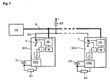
- FIG. 3 shows the components for the determination process of the memory controller numbers in a block diagram.
- the evaluation logic AL in the respective memory controllers SCx monitors the commands from the host system HS, which are transmitted via the bus B. By the pull-up resistor RP, the idle state of the line BA is equal to "1".
- Each memory controller SCx has a clock oscillator OSZ whose frequency is determined by the capacitor Cx and the resistor Rx. The clock generated here is counted up in the counter Z until the count reaches the value W, which is specified by the evaluation logic AL. As soon as this value is reached, the transistor T is turned on and the arbitration line BA is pulled to "0".
- the evaluation logic AL is also connected to the arbitration line BA and then monitors it to see if another memory controller SCx has previously driven the bus to "0".
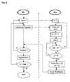
- FIG. 4 shows the sequence of determining the controller numbers Sx.
- the host system sends a reset command, which sets the repeat counter N to 0 in the connected controllers SCx. Thereafter, the host system sends the determination command to the memory controllers SCx. They have waited for the command and increase the repeat counter by 1. They start the counter Z. While waiting for the random value W to reach the count, the controller monitors the arbitration line BA. If the line BA assumes the state "0", another memory controller SCx has determined its controller number Sx and this controller returns to the standby state. If the count Z establishes the value W, this controller drives the arbitration line to "0" for a predetermined time, indicating that it has determined its controller number Sx.
- the controller number Sx corresponds to the value of the repeat counter N.
- the host system HS is sent an acknowledgment of the acceptance of the controller number Sx.
- the host system HS monitors the bus B for a transmission confirmation. If no confirmation is received within a predetermined time limit, the host system starts the determination process from scratch. If the confirmation is received within the specified time, the host system registers this process. When the retry counter N has reached the maximum value MAX corresponding to the number of the predetermined memory controllers, the determination process is completed. Otherwise, further determination commands are sent.
Landscapes
- Engineering & Computer Science (AREA)
- Theoretical Computer Science (AREA)
- Physics & Mathematics (AREA)
- General Engineering & Computer Science (AREA)
- General Physics & Mathematics (AREA)
- Techniques For Improving Reliability Of Storages (AREA)
- Read Only Memory (AREA)
- Communication Control (AREA)
- Information Transfer Systems (AREA)
- Mobile Radio Communication Systems (AREA)
- Use Of Switch Circuits For Exchanges And Methods Of Control Of Multiplex Exchanges (AREA)
Description
- Die Erfindung betrifft ein Speichersystem, welches mit mehreren, an einem getakteten Bus parallel angeordneten Speichercontrollern und jeweils den Speichercontrollern zugeordneten Speicherchips gebildet ist und über den Bus mit einem Hostsystem mit Speicheroperationskommandos unter Verwendung von logischen Speichersektornummern kommuniziert.
- Die Größe eines Speichersystems, angeschlossen an ein Hostsystem, ist durch die Merkmale des Speichercontrollers begrenzt. Diese Speichercontroller sind aus Preisgründen sehr einfach aufgebaut und besitzen üblicherweise folgende Merkmale:
- bis zu 100 Anschlusspins, da preiswerte Standardgehäuse verwendet werden,
- bis zu 10 Chipselect-Signale zur Auswahl von Speicherchips,
- bis zu 16 KByte interner RAM-Speicher.
- Der Erfindung liegt die Aufgabe zugrunde, größere Speichersysteme als sie mit nur einem standardmäßigen Speichercontroller realisierbar sind, durch die Kombination von mehreren standardmäßigen Speichercontrollern ohne den Einsatz zusätzlicher Bauelemente zu bilden, wobei die maximale Größe nur durch die Anzahl der eingesetzten Speichercontroller begrenzt ist. Um mit der durch Standardgehäuse vorgegebenen Anzahl von Anschlusspins auszukommen, soll für die Zusammenschaltung mehrer Speichercontroller nur eine minimale Anzahl von Anschlusspins benötigt werden.
- Gelöst wird die Aufgabe erfindungsgemäß dadurch, dass das Speichersystem mit mehreren, an einem getakteten Bus parallel angeordneten Speichercontrollern und jeweils den Speichercontrollern zugeordneten Speicherchips gebildet ist und dabei über den Bus mit einem Hostsystem mit Speicheroperationskommandos unter Verwendung von logischen Speichersektornummern kommuniziert, wobei bei einer vom Hostsystem angeforderten Speicheroperation der jeweils für einen Bereich von logischen Speichersektornummern betroffene Speichercontroller den Bus für die Kommunikation mit dem Hostsystem mittels einer Arbitrierung über eine Arbitrierungsleitung zwischen den Speichercontrollern übernimmt.
- Vorteilhafte Ausgestaltungen der Erfindung sind in den Unteransprüchen beschrieben.
- In PC-Systemen, digitalen Kameras oder in ähnlichen Geräten, hier als Hostsystem bezeichnet, wird über einen Bus auf ein Speichersystem zugegriffen und über Speicheroperationskommandos mit diesem kommuniziert. Dieser Bus kann als sogenannte PCMCIA-Schnittstelle, IDE-Schnittstelle oder dergleichen ausgeführt sein. Mit den verschiedenen Einsatzfällen der Hostsysteme ist ein skalierbarer Speicher gefordert.
Durch die Parallelschaltung von mehreren Speichercontrollern mit jeweils zugeordneten Speicherchips in einer vom Controller maximal verwaltbaren Anzahl wird mit dem Einsatz von immer gleichen Speichercontrollern eine skalierbare Speichergröße erreicht, die keine weiteren Bauteile benötigt, solange die physikalische Spezifikation des Busses eingehalten wird. Die Kommunikation der Controller mit dem Hostsystem erfolgt unter Verwendung von standardisierten Kommandos, bei denen der Speicher mit logischen Speichersektornummern adressiert ist. Durch ein Arbitrierungsverfahren sind jedem Speichercontroller exklusiv Bereiche von logischen Speichersektornummern zugeordnet. Bei Hostkommandos, welche die jeweiligen logischen Speichersektornummern betreffen, übernimmt der zugeordnete Speichercontroller die Abarbeitung des Kommandos. Das Arbitrierungsverfahren stellt sicher, dass alle logischen Speichersektornummern jeweils von einem der Controller bearbeitet werden und sich bei einem Kommando, z.B. einem Lesekommando für einen Speicherbereich von mehreren Sektornummern, die Controller entsprechend ergänzen und jeweils den Bus zum geeigneten Zeitpunkt übernehmen. - Da mehrere Speichercontroller mit dem Hostsystem kommunizieren, ist es vorteilhaft, dass einer der Speichercontroller als Master an dem Bus bestimmt ist. Dieser führt solange die Kommunikation mit dem Hostsystem durch, wie kein anderer Speichercontroller aufgrund der zugeordneten Speichersektomummer die Kommunikation auf dem Bus übernimmt. Insbesondere werden vom Master Speicheroperationen ausgeführt und beantwortet, die das Speichersystem als Ganzes betreffen. Solche Speicheroperationen sind beispielsweise: "Reset", "Initialisierung", "SetFeatures", "Diagnose". Bei einigen Speicheroperationen werden die Kommandos von allen Speichercontrollern ausgeführt, die Kommunikation über den Status wird aber nur vom Master mit dem Hostsystem geführt.
- Ein wesentlicher Vorteil der erfindungsgemäßen Ausführung des Speichersystems ist die Verwendung nur einer einzigen Leitung zur Arbitrierung des Busses zwischen den Speichercontrollern. Diese Leitung ist als Tri-State-Leitung ausgeführt und besitzt die drei elektrischen Zustände "0", "1", "Tri-State". Dabei ist dann z.B. der Zustand "0" dem logischen "belegt" des Busses und der Zustand "1" dem logischen "freigegeben" zugeordnet.
Bei der Initialisierung der Controller erhalten die Controller Nummern, über die auch der zugeordnete Bereich von logischen Speichersektornummern festgelegt ist. So ist z.B. bei vier Controllern der Controller 1 den Speichersektornummern 0,4,8,12,..... zugeordnet, der Controller 2 den Speichersektornummern 1,5,9,13,...., der Controller 3 den Speichersektomummem 2,6,10,14,...., der Controller 4 den Speichersektornummern 3,7,11,15,.... Wenn nun durch ein Lesekommando die Sektoren 4-11 gelesen werden sollen, übernimmt zuerst der Controller 1 für den Speichersektor 4 den Bus, indem er die Tri-State-Leitung auf "0" zieht. Wenn der Speichersektor 4 übertragen ist, gibt der Controller1 den Bus frei, indem er die Tri-State-Leitung auf "1" schaltet oder in den "Tri-State-Zustand" geht. Danach übernimmt der Controller 2 für den Speichersektor 5 den Bus auf gleiche Art und Weise. So wird der Bus nacheinander fortlaufend von den Controllern übernommen, bis alle angeforderten Speichersektoren, in diesem Fall bis Sektor 11, übertragen sind. - Um einen sauberen Wechsel der Kontrolle über den Bus zwischen den Controllern zu erreichen, ist es vorteilhaft, eine Schutzzeit einzuhalten, in welcher die Tri-State-Leitung definiert auf "freigegeben" getrieben ist. Die Zeitkonstante der Tri-State-Leitung mit einem Pull-Up-Widerstand ist bei einem schnellen Busbetrieb nicht kurz genug. Eine günstige Schutzzeit ist eine Taktlänge auf dem Bus.
- Wie oben beschrieben, ist es günstig, die Zuordnung der Speichercontroller zu logischen Speichesektornummern so vorzunehmen, dass aufeinanderfolgenden Speichersektornummern unterschiedliche Controller zugeordnet sind. Damit können so viele logische Speichersektoren quasi parallel geschrieben oder gelesen werden, wie Speichercontroller vorhanden sind. Damit wird eine hohe Arbeitsgeschwindigkeit des Speichersystems erreicht.
- Eine besonders vorteilhafte Ausführung des Speichersystems ergibt sich bei dem Einsatz von Flashspeichern als Speicherchips. Bei diesem Speichertyp treten gegenüber den Zeiten des Lesens lange Schreib- und Löschzeiten auf. Durch das Überlappen ("Interleave") der Bedienung von fortlaufenden logischen Speichersektornummern durch unterschiedliche Speichercontroller und damit auch unterschiedlichen Speicherchips laufen diese Schreib- und Löschvorgänge quasi parallel ab, was die Geschwindigkeit des gesamten Speichersystems steigert. Dabei können die realen Speichersektoren, auch "Pages" genannt, die in die Flashchips geschrieben werden, eine vielfache Größe der logischen Speichersektoren besitzen.
- Ein einfacher und preisgünstiger Speicheraufbau ergibt sich, wenn die Speichercontroller zusammen auf einem Halbleitersubstrat integriert sind. Bei einem solchen Aufbau entfallen die Kosten für die einzelnen Gehäuse, und die Anzahl der Anschlusspins untereinander ist nicht von Bedeutung. Insbesondere sind dann auf dem Halbleitersubstrat auch zusätzliche Kontrollregister untergebracht, mit denen beispielsweise die Reihenfolge der einzelnen Speichercontroller am Bus festgelegt wird und der Master bestimmt ist.
- Falls solche Kontrollregister nicht vorhanden sind, wird während der Initialisierung des Speichersystems die Bestimmung des Masters und die Festlegung der Reihenfolge der Speichercontroller am Bus durch nachfolgendes Verfahren festgelegt:
Dem initialisierenden Hostsystem ist die Größe des Speichersystems und die Anzahl der eingesetzten Speichercontroller bekannt.
Die Tri-State-Leitung befindet sich im Zustand "freigegeben". Das Hostsystem sendet über den Bus ein Bestimmungskommando, das von allen angeschlossenen Speichercontrollern aufgenommen wird. Die Speichercontroller bestimmen anhand eines Zählers, der den angelegten Takt zählt, eine Wartezeit. Derjenige Speichercontroller, bei dem die Wartezeit als erstes abläuft, zieht die Tri-State-Leitung für einen definierten Zeitraum auf "belegt". Er besitzt damit die Speichercontrollernummer 1, und er ist auch als Master bestimmt. Die anderen Speichercontroller registrieren diesen Vorgang. Der Master sendet an das Hostsystem ein Bestätigungssignal. Daraufhin wiederholt das Hostsystem das Bestimmungskommando. Der Master zieht sich jetzt aus der Bestimmungsprozedur zurück. Alle anderen Speichercontroller warten wieder gemäß ihrer intern bestimmten Wartezeit. Derjenige Speichercontroller, der jetzt die kürzeste Wartezeit hat, belegt wieder die Tri-State-Leitung und bekommt damit die nächst Speichercontrollernummer zugeteilt. Der Master bestätigt wieder den Vorgang gegenüber dem Hostsystem. Der Speichercontroller, der jetzt eine Controllernummer erhalten hat, zieht sich auch aus dem Vergabeverfahren zurück. Das Hostsystem wiederholt den Vorgang mit dem Bestimmungskommando so oft, wie es der Anzahl der Speichercontroller entspricht. Bekommt das Hostsystem keine Bestätigung auf ein Bestimmungskommando, da eine Controllernummer aufgrund von gleich langen Wartezeiten doppelt vergeben wurde, wiederholt es das gesamte Verfahren von vorn. - Die Wartezeit beim Bestimmungsverfahren wird vorteilhafterweise aus einem Zähler im Speichercontroller mittels eines zufällig bestimmten Zählerstandes abgeleitet. Der hier hochgezählte Takt wird in jedem Speichercontroller separat mit einem RC-Oszillator erzeugt, der aufgrund von Bauteiletoleranzen jeweils nicht synchron zu den anderen läuft. Daher ist die Wahrscheinlichkeit von gleich langen Wartezeiten, auch bei gleicher Zufallszahl für den Zählerstand, äußerst gering.
- Nach der Bestimmung der Controllernummern wird in alle Speichercontroller ein sogenannter Ankersektor geschrieben, der dann die Angaben über die Speichergröße entsprechend der Gesamtanzahl der logischen Sektornummern, die Anzahl der Controller und der Pagegröße enthält. Damit besitzt der Speichercontroller alle notwendigen Informationen, um an der Kommunikation über den Bus teilzunehmen.
- Die Ausgestaltung der Erfindung ist in den Figuren beispielhaft beschrieben.
Fig. 1 zeigt ein Blockschaltbild des Speichersystems
Fig. 2 zeigt das ergänzte Blockschaltbild bei Integration der Speichercontroller auf einem Halbleitersubstrat.
Fig. 3 zeigt ein Blockschaltbild für den Bestimmungsprozess der Speichercontrollernummern
Fig. 4 zeigt ein Ablaufdiagramm für das Bestimmungsverfahren der Speichercontrollernummern - In Fig. 1 kommuniziert das Hostsystem HS über den Bus B mit den Speichercontrollern SCx. Das x steht für die fortlaufenden Ziffern 1 bis 4. Die Speichercontroller SCx sind parallel am Bus B angeschlossen. Jeder Speichercontroller SCx steuert Speicherchips Fx, die vorzugsweise in Flashtechnologie aufgebaut sind. Zusätzlich zum Bus B sind die Speichercontroller SCx auch mit der Arbitrierungsleitung BA verbunden, die den jeweiligen Zustand "belegt" oder "freigegeben" angibt. Diese Leitung BA ist als Tri-State-Leitung mit Pull-Up-Widerstand ausgeführt. Der erste Speichercontroller S C 1 ist gleichzeitig als Master M bestimmt.
- Fig. 2 zeigt das gleiche Blockschaltbild wie Fig. 1 ohne die Speicherchips Fx. Hier sind die Speichercontroller SCx auf dem Halbleitersubstrat H integriert. Zusätzlich ist auf dem Halbleitersubstrat H das Kontrollregister KR untergebracht, welches für jeden Speichercontroller SCx ein Feld enthält, das die Controllernummer Sx und die Bestimmung des Masters M enthält. Diese Werte werden bei der Initialisierung des Speichersystems in das Kontrollregister KR geschrieben.
- In Fig. 3 sind die Komponenten für den Bestimmungsprozess der Speichercontrollernummern in einem Blockschaltbild dargestellt. Die Auswertelogik AL in den jeweiligen Speichercontrollern SCx überwacht die Kommandos vom Hostsystem HS, die über den Bus B übertragen werden. Durch den Pull-Up-Widerstand RP ist der Ruhezustand der Leitung BA gleich "1".
Jeder Speichercontroller SCx besitzt einen Taktoszillator OSZ, dessen Frequenz von dem Kondensator Cx und dem Widerstand Rx bestimmt ist. Der hier erzeugte Takt wird solange im Zähler Z hochgezählt, bis der Zählerstand den Wert W erreicht, der von der Auswertelogik AL vorgegeben ist. Sobald dieser Wert erreicht ist, wird der Transistor T durchgeschaltet und die Arbitrierungsleitung BA auf "0" gezogen. - Auch die Auswertelogik AL ist an die Arbitrierungsleitung BA angeschlossen und überwacht diese daraufhin, ob ein anderer Speichercontroller SCx den Bus vorher auf "0" getrieben hat.
- In Fig. 4 ist der Ablauf der Bestimmung der Controllernummern Sx dargestellt. Zunächst sendet das Hostsystem ein Reset-Kommando, das bei den angeschlossenen Controllern SCx den Wiederholungszähler N auf 0 setzt. Danach sendet das Hostsystem das Bestimmungskommando an die Speichercontroller SCx. Diese haben auf das Kommando gewartet und erhöhen den Wiederholungszähler um 1. Sie starten den Zähler Z. Während auf das Erreichen des Zählerstandes auf den Zufallswert W gewartet wird, überwacht der Controller die Arbitrierungsleitung BA. Falls die Leitung BA den Zustand "0" annimmt, hat ein anderer Speichercontroller SCx seine Controllernummer Sx bestimmt und dieser Controller geht wieder in die Wartestellung. Falls der Zählerstand Z den Wert W erricht, treibt dieser Controller die Arbitrierungsleitung für eine vorbestimmte Zeit auf "0" und zeigt damit an, dass er seine Controllernummer Sx bestimmt hat. Die Controllernummer Sx entspricht dem wert des Wiederholungszählers N. Dem Hostsystem HS wird eine Bestätigung der Übernahme der Controllernummer Sx gesendet.
Das Hostsystem HS überwacht den Bus B auf eine Sendebestätigung. Wird innerhalb eines vorgegeben Zeitlimits keine Bestätigung erhalten, beginnt das Hostsystem den Bestimmungsprozess von vorn. Wird die Bestätigung innerhalb der vorgegebenen Zeit erhalten, registriert das Hostsystem diesen Vorgang.
Wenn der Wiederholungszähler N den Maximalwert MAX erreicht hat, welcher der Anzahl der vorgegebenen Speichercontroller entspricht, ist der Bestimmungsprozess beendet. Anderenfalls werden weitere Bestimmungskommandos gesendet. -
- AL
- Auswertelogik
- B
- Bus
- BA
- Arbitrierungsleitung für den Bus
- Cx
- Kondensator am Oszillator x
- Fx
- Speicherchips
- H
- Halbleitersubstrat
- HS
- Hostsystem
- KR
- Kontrollregister
- M
- Master
- Max
- Maximale Zahl der Speichercontroller
- N
- Wiederholungszahl des Bestimmekommandos
- OSZ
- Oszillator
- RP
- Pull-Up-Widerstand
- Rx
- Widerstand am Oszillator x
- Sx
- Controllernummern
- SCx
- Speichercontroller
- T
- Transistor
- W
- Zufallswert
- x
- 1 .. 4, fortlaufende Nummer
- Z
- Zähler
- =
- Vergleicher
Aus der Anmeldeschrift mit dem Aktenzeichen DE102 27 256.5 ist beispielsweise eine Anordnung bekannt, bei der die Speicherchips eines größeren Speichers über zusätzliche Bauteile an einen Controller angeschlossen sind.
In der Patentschrift US 6,397,314 ist eine Anordnung von Speicherchips an einem Controller beschrieben, wobei der Controller einen doppelt breiten Datenbus besitzt, um zwei Speicherchips parallel mit Daten zu versorgen. Dies bedingt einen nicht standardmäßigen Speichercontroller, der zusätzliche Anschlusspins benötigt. Diese Anordnung ist außerdem nicht auf noch größere Anordnungen anwendbar, da sie auf zwei simultan ansprechbare Speicherchips begrenzt ist.
In dem Patent US 5,212,799 ist ein Speichersystem mit mehreren Prozessoren und Speichercontrollern beschrieben, dass durch zwischen den Prozessoren und Speichercontrollern geführte BUSY-Leitungen die Verfälschung von Daten beim Zugriff mehrere Prozessoren auf die Speichercontroller vermeidet.
Claims (13)
- Speichersystem, welches mit mehreren, an einem getakteten Bus (B) parallel angeordneten Speichercontrollern (SCx) und jeweils den Speichercontrollern (SCx) zugeordneten Speicherchips (Fx) gebildet ist und über den Bus (B) mit einem Hostsystem (HS) mit Speicheroperationskommandos unter Verwendung von logischen Speichersektornummern kommuniziert, wobei bei einer vom Hostsystem (HS) angeforderten Speicheroperation der jeweils für einen Bereich von logischen Speichersektornummern betroffene Speichercontroller (SCx) den Bus für die Kommunikation mit dem Hostsystem (HS) mittels einer Arbitrierung über eine einzige Arbitrierungsleitung (BA) übernimmt, dadurch gekennzeichnet, dass die Arbitrierungsleitung ausschließlich zwischen den Speichercontrollern (SCx) geschaltet ist.
- Speichersystem nach Anspruch 1, dadurch gekennzeichnet, dass einer der parallelen Speichercontroller (SCx) als Master (M) am Bus (B) bestimmt ist, und dieser, solange keiner der anderen Speichercontroller (SCx) den Bus (B) übernommen hat, die Kommunikation mit dem Hostsystem (HS) durchführt.
- Speichersystem nach Anspruch 1, dadurch gekennzeichnet, dass die Arbitrierung des Busses (B) anhand der angesprochenen Speichersektomummer und über eine einzige Tri-State-Arbitrierungsleitung (BA) erfolgt, welche die Belegung des Busses (B) durch den betroffenen Speichercontroller (SCx) während der Kommunikationszeit mit einem Belegt-Signal angibt.
- Speichersystem nach Anspruch 3, dadurch gekennzeichnet, dass bei der Freigabe des Busses (B) durch einen Speichercontroller (SCx) auf der Arbitrierungsleitung (BA) eine Schutzzeit eingefügt ist, in der die Arbitrierungsleitung (BA) aktiv auf Freigabe getrieben ist.
- Speichersystem nach Anspruch 4, dadurch gekennzeichnet, dass die Schutzzeit einer Taktlänge des Busses (B) entspricht.
- Speichersystem nach Anspruch 1, dadurch gekennzeichnet, dass für aufeinanderfolgende logische Speichersektornummern unterschiedliche Speichercontroller (SCx) zugeordnet sind.
- Speichersystem nach Anspruch 1, dadurch gekennzeichnet, dass die Speicherchips (Fx) blockweise löschbare Flashspeicher sind.
- Speichersystem nach einem der vorstehenden Ansprüche, dadurch gekennzeichnet, dass die Speichercontroller (SCx) gemeinsam auf einem Halbleitersubstrat (H) angeordnet sind.
- Speichersystem nach Anspruch 8, dadurch gekennzeichnet, dass die Bestimmung die Reihenfolge der Speichercontroller (SCx) am Bus (B) und des Masters (M) durch eine Programmierung eines Kontrollregisters (KR) zu den jeweiligen Speichercontrollern (SCx) erfolgt.
- Verfahren zur Bestimmung der Reihenfolge der Speichercontroller (SCx) am Bus (B), dadurch gekennzeichnet, dass• auf ein wiederholtes Bestimmungskommando des Hostsystems (HS) jeweils ein Speichercontroller (SCx) nach einer zufällig bestimmtem Zeit eine Arbitrierungsleitung (BA) für einen definierten Zeitraum belegt, sofern kein anderer Controller (SCx) die Leitung (BA) vorher belegt hat,• aus der Wiederholungszahl dieses Bestimmungskommandos dieser Controller seine Controllernummer (Sx) ableitet,• jeweils ein Bestätigungssignal zum Hostsystem (HS) gemeldet wird,• sich der jeweilige Speichercontroller (SCx) nach der Bestätigung aus dem Bestimmungsverfahren zurückzieht.
- Verfahren nach Anspruch 10, dadurch gekennzeichnet, dass der Speichercontroller (SCx) mit der Controllernummer 1 als Master (M) bestimmt ist.
- Verfahren nach Anspruch 10, dadurch gekennzeichnet, dass das Hostsystem (HS) die Bestimmungsvorgang wiederholt, falls nicht genügend Bestätigungen der Bestimmung gemeldet werden.
- Verfahren nach Anspruch 10, dadurch gekennzeichnet, dass die zufällige Zeit zur Belegung der Arbitrierungsleitung (BA) von einem Zähler abgeleitet ist, der von Bauteiletoleranzen abhängig ist.
Applications Claiming Priority (3)
| Application Number | Priority Date | Filing Date | Title |
|---|---|---|---|
| DE10256502A DE10256502A1 (de) | 2002-12-04 | 2002-12-04 | Speichersystem mit mehreren Speichercontrollern und Verfahren zu deren Synchronisierung |
| DE10256502 | 2002-12-04 | ||
| PCT/EP2003/013495 WO2004051490A2 (de) | 2002-12-04 | 2003-12-01 | Speichersystem mit mehreren speichercontrollern and verfahren zu deren synchronisierung |
Publications (2)
| Publication Number | Publication Date |
|---|---|
| EP1567938A2 EP1567938A2 (de) | 2005-08-31 |
| EP1567938B1 true EP1567938B1 (de) | 2006-10-04 |
Family
ID=32335931
Family Applications (1)
| Application Number | Title | Priority Date | Filing Date |
|---|---|---|---|
| EP03782258A Expired - Lifetime EP1567938B1 (de) | 2002-12-04 | 2003-12-01 | Speichersystem mit mehreren speichercontrollern and verfahren zu deren synchronisierung |
Country Status (10)
| Country | Link |
|---|---|
| US (1) | US7415579B2 (de) |
| EP (1) | EP1567938B1 (de) |
| JP (1) | JP2006509279A (de) |
| KR (1) | KR20050084876A (de) |
| CN (1) | CN100409212C (de) |
| AT (1) | ATE341788T1 (de) |
| AU (1) | AU2003289919A1 (de) |
| CA (1) | CA2508655A1 (de) |
| DE (2) | DE10256502A1 (de) |
| WO (1) | WO2004051490A2 (de) |
Families Citing this family (5)
| Publication number | Priority date | Publication date | Assignee | Title |
|---|---|---|---|---|
| JP4696501B2 (ja) * | 2004-08-24 | 2011-06-08 | ソニー株式会社 | データ記録方法 |
| US7502256B2 (en) * | 2004-11-30 | 2009-03-10 | Siliconsystems, Inc. | Systems and methods for reducing unauthorized data recovery from solid-state storage devices |
| US9129071B2 (en) | 2012-10-24 | 2015-09-08 | Texas Instruments Incorporated | Coherence controller slot architecture allowing zero latency write commit |
| US10331360B2 (en) * | 2016-09-29 | 2019-06-25 | Intel Corporation | Scalable bandwidth non-volatile memory |
| US11487445B2 (en) * | 2016-11-22 | 2022-11-01 | Intel Corporation | Programmable integrated circuit with stacked memory die for storing configuration data |
Family Cites Families (11)
| Publication number | Priority date | Publication date | Assignee | Title |
|---|---|---|---|---|
| US4376974A (en) * | 1980-03-31 | 1983-03-15 | Ncr Corporation | Associative memory system |
| US4773005A (en) * | 1984-09-07 | 1988-09-20 | Tektronix, Inc. | Dynamic address assignment system |
| US4893302A (en) * | 1988-03-31 | 1990-01-09 | American Telephone And Telegraph Company, At&T Bell Laboratories | Arrangement for switching concentrated telecommunications packet traffic |
| US5265231A (en) * | 1991-02-08 | 1993-11-23 | Thinking Machines Corporation | Refresh control arrangement and a method for refreshing a plurality of random access memory banks in a memory system |
| US5212799A (en) * | 1991-07-31 | 1993-05-18 | Ncr Corporation | Method and apparatus for storing a data block in multiple memory banks within a computer |
| JP4038237B2 (ja) | 1993-11-29 | 2008-01-23 | コーニンクレッカ フィリップス エレクトロニクス エヌ ヴィ | モジュラーシステムにおける順位に基づくアドレス割り当て |
| US5751292A (en) * | 1995-06-06 | 1998-05-12 | Hewlett-Packard Company | Texture mapping method and system |
| US6081878A (en) * | 1997-03-31 | 2000-06-27 | Lexar Media, Inc. | Increasing the memory performance of flash memory devices by writing sectors simultaneously to multiple flash memory devices |
| US6026464A (en) | 1997-06-24 | 2000-02-15 | Cisco Technology, Inc. | Memory control system and method utilizing distributed memory controllers for multibank memory |
| US6330645B1 (en) * | 1998-12-21 | 2001-12-11 | Cisco Technology, Inc. | Multi-stream coherent memory controller apparatus and method |
| JP4688584B2 (ja) * | 2005-06-21 | 2011-05-25 | 株式会社日立製作所 | ストレージ装置 |
-
2002
- 2002-12-04 DE DE10256502A patent/DE10256502A1/de not_active Withdrawn
-
2003
- 2003-12-01 US US10/537,700 patent/US7415579B2/en not_active Expired - Fee Related
- 2003-12-01 JP JP2004556244A patent/JP2006509279A/ja active Pending
- 2003-12-01 CA CA002508655A patent/CA2508655A1/en not_active Abandoned
- 2003-12-01 KR KR1020057007226A patent/KR20050084876A/ko not_active Ceased
- 2003-12-01 AT AT03782258T patent/ATE341788T1/de not_active IP Right Cessation
- 2003-12-01 AU AU2003289919A patent/AU2003289919A1/en not_active Abandoned
- 2003-12-01 EP EP03782258A patent/EP1567938B1/de not_active Expired - Lifetime
- 2003-12-01 DE DE50305302T patent/DE50305302D1/de not_active Expired - Lifetime
- 2003-12-01 WO PCT/EP2003/013495 patent/WO2004051490A2/de not_active Ceased
- 2003-12-01 CN CNB2003801049814A patent/CN100409212C/zh not_active Expired - Fee Related
Also Published As
| Publication number | Publication date |
|---|---|
| WO2004051490A2 (de) | 2004-06-17 |
| US7415579B2 (en) | 2008-08-19 |
| CN1720511A (zh) | 2006-01-11 |
| CN100409212C (zh) | 2008-08-06 |
| DE10256502A1 (de) | 2004-06-24 |
| ATE341788T1 (de) | 2006-10-15 |
| KR20050084876A (ko) | 2005-08-29 |
| CA2508655A1 (en) | 2004-06-17 |
| US20060117150A1 (en) | 2006-06-01 |
| WO2004051490A3 (de) | 2005-01-06 |
| EP1567938A2 (de) | 2005-08-31 |
| JP2006509279A (ja) | 2006-03-16 |
| DE50305302D1 (de) | 2006-11-16 |
| AU2003289919A1 (en) | 2004-06-23 |
Similar Documents
| Publication | Publication Date | Title |
|---|---|---|
| DE2448212C2 (de) | Asynchrone Sammelleitung zur Kommunikation mit selbstbestimmter Priorität zwischen Mutterrechnergeräten und Tochterrechnergeräten | |
| DE3938018C2 (de) | ||
| DE3914265C2 (de) | ||
| DE69029238T2 (de) | Serielle Datenübertragung | |
| DE3300260C2 (de) | ||
| DE3909948C2 (de) | ||
| DE2856483C2 (de) | ||
| DE3810231C2 (de) | ||
| DE3038639C2 (de) | Anordnung zur Datenübertragung zwischen einer Zentraleinheit und n E/A-Einheiten | |
| DE3933849A1 (de) | Prozessorgesteuerte schnittstelle | |
| DE3049774C2 (de) | ||
| DE19614238C1 (de) | Kommunikationssystem mit einer Meisterstation und mindestens einer Sklavenstation | |
| DE19614237C1 (de) | Kommunikationssystem mit einer Meisterstation und mindestens einer Sklavenstation | |
| DE4418862C1 (de) | Speichervorrichtung mit Seitenwählfähigkeit und Speichersystem für seriellen Zugriff | |
| DE69119149T2 (de) | Struktur zur direkten Speicher-zu-Speicher-Übertragung | |
| EP0062141B1 (de) | Schaltungsanordnung zur Eingabe von Steuerbefehlen in ein Mikrocomputersystem | |
| EP1567938B1 (de) | Speichersystem mit mehreren speichercontrollern and verfahren zu deren synchronisierung | |
| DE102004013635A1 (de) | Verfahren und Vorrichtung zur Vergabe von Buszugriffsrechten in Multimaster-Bussystemen | |
| EP4187395A1 (de) | Verfahren und einrichtung zur emulation von übertragungsprotokollen zur ansteuerung von elektronischen bausteinen an einem bussystem | |
| DE3586789T2 (de) | Mikrocomputer mit wenigstens einer ein-/ausgabeeinheit. | |
| DE69024912T2 (de) | Rechnersystem | |
| DE60209761T2 (de) | Anschluss mehrerer prozessoren auf externen speicher mit burst mode | |
| DE4100018C2 (de) | Verfahren zur Bedienungsbedarfsmitteilung zwischen zwei Stationen eines Computerbusses | |
| EP1316891B1 (de) | Datenübertragungseinrichtung | |
| DE102006009034B3 (de) | Verfahren zum Betreiben eines Bussystems sowie Halbleiter-Bauelement, insbesondere Mikroprozessor- bzw. Mikrocontroller |
Legal Events
| Date | Code | Title | Description |
|---|---|---|---|
| PUAI | Public reference made under article 153(3) epc to a published international application that has entered the european phase |
Free format text: ORIGINAL CODE: 0009012 |
|
| 17P | Request for examination filed |
Effective date: 20050527 |
|
| AK | Designated contracting states |
Kind code of ref document: A2 Designated state(s): AT BE BG CH CY CZ DE DK EE ES FI FR GB GR HU IE IT LI LU MC NL PT RO SE SI SK TR |
|
| AX | Request for extension of the european patent |
Extension state: AL LT LV MK |
|
| DAX | Request for extension of the european patent (deleted) | ||
| GRAP | Despatch of communication of intention to grant a patent |
Free format text: ORIGINAL CODE: EPIDOSNIGR1 |
|
| GRAS | Grant fee paid |
Free format text: ORIGINAL CODE: EPIDOSNIGR3 |
|
| GRAA | (expected) grant |
Free format text: ORIGINAL CODE: 0009210 |
|
| AK | Designated contracting states |
Kind code of ref document: B1 Designated state(s): AT BE BG CH CY CZ DE DK EE ES FI FR GB GR HU IE IT LI LU MC NL PT RO SE SI SK TR |
|
| PG25 | Lapsed in a contracting state [announced via postgrant information from national office to epo] |
Ref country code: IE Free format text: LAPSE BECAUSE OF FAILURE TO SUBMIT A TRANSLATION OF THE DESCRIPTION OR TO PAY THE FEE WITHIN THE PRESCRIBED TIME-LIMIT Effective date: 20061004 Ref country code: FI Free format text: LAPSE BECAUSE OF FAILURE TO SUBMIT A TRANSLATION OF THE DESCRIPTION OR TO PAY THE FEE WITHIN THE PRESCRIBED TIME-LIMIT Effective date: 20061004 Ref country code: SI Free format text: LAPSE BECAUSE OF FAILURE TO SUBMIT A TRANSLATION OF THE DESCRIPTION OR TO PAY THE FEE WITHIN THE PRESCRIBED TIME-LIMIT Effective date: 20061004 Ref country code: SK Free format text: LAPSE BECAUSE OF FAILURE TO SUBMIT A TRANSLATION OF THE DESCRIPTION OR TO PAY THE FEE WITHIN THE PRESCRIBED TIME-LIMIT Effective date: 20061004 Ref country code: NL Free format text: LAPSE BECAUSE OF FAILURE TO SUBMIT A TRANSLATION OF THE DESCRIPTION OR TO PAY THE FEE WITHIN THE PRESCRIBED TIME-LIMIT Effective date: 20061004 Ref country code: RO Free format text: LAPSE BECAUSE OF FAILURE TO SUBMIT A TRANSLATION OF THE DESCRIPTION OR TO PAY THE FEE WITHIN THE PRESCRIBED TIME-LIMIT Effective date: 20061004 Ref country code: CZ Free format text: LAPSE BECAUSE OF FAILURE TO SUBMIT A TRANSLATION OF THE DESCRIPTION OR TO PAY THE FEE WITHIN THE PRESCRIBED TIME-LIMIT Effective date: 20061004 |
|
| REG | Reference to a national code |
Ref country code: GB Ref legal event code: FG4D Free format text: NOT ENGLISH |
|
| REG | Reference to a national code |
Ref country code: CH Ref legal event code: EP |
|
| REG | Reference to a national code |
Ref country code: IE Ref legal event code: FG4D Free format text: LANGUAGE OF EP DOCUMENT: GERMAN |
|
| REF | Corresponds to: |
Ref document number: 50305302 Country of ref document: DE Date of ref document: 20061116 Kind code of ref document: P |
|
| PG25 | Lapsed in a contracting state [announced via postgrant information from national office to epo] |
Ref country code: BE Free format text: LAPSE BECAUSE OF NON-PAYMENT OF DUE FEES Effective date: 20061231 Ref country code: MC Free format text: LAPSE BECAUSE OF NON-PAYMENT OF DUE FEES Effective date: 20061231 |
|
| PG25 | Lapsed in a contracting state [announced via postgrant information from national office to epo] |
Ref country code: DK Free format text: LAPSE BECAUSE OF FAILURE TO SUBMIT A TRANSLATION OF THE DESCRIPTION OR TO PAY THE FEE WITHIN THE PRESCRIBED TIME-LIMIT Effective date: 20070104 Ref country code: BG Free format text: LAPSE BECAUSE OF FAILURE TO SUBMIT A TRANSLATION OF THE DESCRIPTION OR TO PAY THE FEE WITHIN THE PRESCRIBED TIME-LIMIT Effective date: 20070104 Ref country code: SE Free format text: LAPSE BECAUSE OF FAILURE TO SUBMIT A TRANSLATION OF THE DESCRIPTION OR TO PAY THE FEE WITHIN THE PRESCRIBED TIME-LIMIT Effective date: 20070104 |
|
| PG25 | Lapsed in a contracting state [announced via postgrant information from national office to epo] |
Ref country code: ES Free format text: LAPSE BECAUSE OF FAILURE TO SUBMIT A TRANSLATION OF THE DESCRIPTION OR TO PAY THE FEE WITHIN THE PRESCRIBED TIME-LIMIT Effective date: 20070115 |
|
| PG25 | Lapsed in a contracting state [announced via postgrant information from national office to epo] |
Ref country code: PT Free format text: LAPSE BECAUSE OF FAILURE TO SUBMIT A TRANSLATION OF THE DESCRIPTION OR TO PAY THE FEE WITHIN THE PRESCRIBED TIME-LIMIT Effective date: 20070316 |
|
| NLV1 | Nl: lapsed or annulled due to failure to fulfill the requirements of art. 29p and 29m of the patents act | ||
| ET | Fr: translation filed | ||
| REG | Reference to a national code |
Ref country code: IE Ref legal event code: FD4D |
|
| PLBE | No opposition filed within time limit |
Free format text: ORIGINAL CODE: 0009261 |
|
| STAA | Information on the status of an ep patent application or granted ep patent |
Free format text: STATUS: NO OPPOSITION FILED WITHIN TIME LIMIT |
|
| 26N | No opposition filed |
Effective date: 20070705 |
|
| BERE | Be: lapsed |
Owner name: HYPERSTONE A.G. Effective date: 20061231 |
|
| PG25 | Lapsed in a contracting state [announced via postgrant information from national office to epo] |
Ref country code: AT Free format text: LAPSE BECAUSE OF NON-PAYMENT OF DUE FEES Effective date: 20061201 |
|
| PG25 | Lapsed in a contracting state [announced via postgrant information from national office to epo] |
Ref country code: GR Free format text: LAPSE BECAUSE OF FAILURE TO SUBMIT A TRANSLATION OF THE DESCRIPTION OR TO PAY THE FEE WITHIN THE PRESCRIBED TIME-LIMIT Effective date: 20070105 |
|
| PG25 | Lapsed in a contracting state [announced via postgrant information from national office to epo] |
Ref country code: EE Free format text: LAPSE BECAUSE OF FAILURE TO SUBMIT A TRANSLATION OF THE DESCRIPTION OR TO PAY THE FEE WITHIN THE PRESCRIBED TIME-LIMIT Effective date: 20061004 |
|
| PG25 | Lapsed in a contracting state [announced via postgrant information from national office to epo] |
Ref country code: TR Free format text: LAPSE BECAUSE OF FAILURE TO SUBMIT A TRANSLATION OF THE DESCRIPTION OR TO PAY THE FEE WITHIN THE PRESCRIBED TIME-LIMIT Effective date: 20061004 Ref country code: HU Free format text: LAPSE BECAUSE OF FAILURE TO SUBMIT A TRANSLATION OF THE DESCRIPTION OR TO PAY THE FEE WITHIN THE PRESCRIBED TIME-LIMIT Effective date: 20070405 Ref country code: LU Free format text: LAPSE BECAUSE OF NON-PAYMENT OF DUE FEES Effective date: 20061201 |
|
| REG | Reference to a national code |
Ref country code: CH Ref legal event code: PL |
|
| PG25 | Lapsed in a contracting state [announced via postgrant information from national office to epo] |
Ref country code: LI Free format text: LAPSE BECAUSE OF NON-PAYMENT OF DUE FEES Effective date: 20071231 Ref country code: CH Free format text: LAPSE BECAUSE OF NON-PAYMENT OF DUE FEES Effective date: 20071231 |
|
| PG25 | Lapsed in a contracting state [announced via postgrant information from national office to epo] |
Ref country code: CY Free format text: LAPSE BECAUSE OF FAILURE TO SUBMIT A TRANSLATION OF THE DESCRIPTION OR TO PAY THE FEE WITHIN THE PRESCRIBED TIME-LIMIT Effective date: 20061004 |
|
| PGFP | Annual fee paid to national office [announced via postgrant information from national office to epo] |
Ref country code: GB Payment date: 20101213 Year of fee payment: 8 Ref country code: IT Payment date: 20101223 Year of fee payment: 8 |
|
| PGFP | Annual fee paid to national office [announced via postgrant information from national office to epo] |
Ref country code: FR Payment date: 20111214 Year of fee payment: 9 |
|
| PGFP | Annual fee paid to national office [announced via postgrant information from national office to epo] |
Ref country code: DE Payment date: 20121221 Year of fee payment: 10 |
|
| GBPC | Gb: european patent ceased through non-payment of renewal fee |
Effective date: 20121201 |
|
| REG | Reference to a national code |
Ref country code: FR Ref legal event code: ST Effective date: 20130830 |
|
| PG25 | Lapsed in a contracting state [announced via postgrant information from national office to epo] |
Ref country code: FR Free format text: LAPSE BECAUSE OF NON-PAYMENT OF DUE FEES Effective date: 20130102 Ref country code: GB Free format text: LAPSE BECAUSE OF NON-PAYMENT OF DUE FEES Effective date: 20121201 |
|
| PG25 | Lapsed in a contracting state [announced via postgrant information from national office to epo] |
Ref country code: IT Free format text: LAPSE BECAUSE OF NON-PAYMENT OF DUE FEES Effective date: 20121201 |
|
| REG | Reference to a national code |
Ref country code: DE Ref legal event code: R119 Ref document number: 50305302 Country of ref document: DE |
|
| REG | Reference to a national code |
Ref country code: DE Ref legal event code: R119 Ref document number: 50305302 Country of ref document: DE Effective date: 20140701 |
|
| PG25 | Lapsed in a contracting state [announced via postgrant information from national office to epo] |
Ref country code: DE Free format text: LAPSE BECAUSE OF NON-PAYMENT OF DUE FEES Effective date: 20140701 |