EP1567209B1 - Vorrichtung zum vorrübergehenden festhalten einer nadelschutzkappe einer injektionsvorrichtung - Google Patents
Vorrichtung zum vorrübergehenden festhalten einer nadelschutzkappe einer injektionsvorrichtung Download PDFInfo
- Publication number
- EP1567209B1 EP1567209B1 EP03811706A EP03811706A EP1567209B1 EP 1567209 B1 EP1567209 B1 EP 1567209B1 EP 03811706 A EP03811706 A EP 03811706A EP 03811706 A EP03811706 A EP 03811706A EP 1567209 B1 EP1567209 B1 EP 1567209B1
- Authority
- EP
- European Patent Office
- Prior art keywords
- receiving portion
- housing
- injection apparatus
- holding means
- loading station
- Prior art date
- Legal status (The legal status is an assumption and is not a legal conclusion. Google has not performed a legal analysis and makes no representation as to the accuracy of the status listed.)
- Expired - Lifetime
Links
- 238000002347 injection Methods 0.000 title claims abstract description 24
- 239000007924 injection Substances 0.000 title claims abstract description 24
- 230000001681 protective effect Effects 0.000 title 1
- 229940090047 auto-injector Drugs 0.000 claims description 22
- 238000002360 preparation method Methods 0.000 claims description 3
- 230000008878 coupling Effects 0.000 claims 1
- 238000010168 coupling process Methods 0.000 claims 1
- 238000005859 coupling reaction Methods 0.000 claims 1
- 230000037431 insertion Effects 0.000 claims 1
- 238000003780 insertion Methods 0.000 claims 1
- 239000013641 positive control Substances 0.000 claims 1
- 238000000034 method Methods 0.000 abstract 1
- 210000002105 tongue Anatomy 0.000 description 2
- 208000027418 Wounds and injury Diseases 0.000 description 1
- 239000013543 active substance Substances 0.000 description 1
- 238000010276 construction Methods 0.000 description 1
- 230000006378 damage Effects 0.000 description 1
- 208000014674 injury Diseases 0.000 description 1
- 239000007779 soft material Substances 0.000 description 1
- 239000000243 solution Substances 0.000 description 1
Images
Classifications
-
- A—HUMAN NECESSITIES
- A61—MEDICAL OR VETERINARY SCIENCE; HYGIENE
- A61M—DEVICES FOR INTRODUCING MEDIA INTO, OR ONTO, THE BODY; DEVICES FOR TRANSDUCING BODY MEDIA OR FOR TAKING MEDIA FROM THE BODY; DEVICES FOR PRODUCING OR ENDING SLEEP OR STUPOR
- A61M5/00—Devices for bringing media into the body in a subcutaneous, intra-vascular or intramuscular way; Accessories therefor, e.g. filling or cleaning devices, arm-rests
- A61M5/178—Syringes
- A61M5/31—Details
- A61M5/32—Needles; Details of needles pertaining to their connection with syringe or hub; Accessories for bringing the needle into, or holding the needle on, the body; Devices for protection of needles
- A61M5/3205—Apparatus for removing or disposing of used needles or syringes, e.g. containers; Means for protection against accidental injuries from used needles
- A61M2005/3208—Apparatus for removing or disposing of used needles or syringes, e.g. containers; Means for protection against accidental injuries from used needles by application of rotational movement to the needle hub, e.g. by use of electrically driven toothed wheels
-
- A—HUMAN NECESSITIES
- A61—MEDICAL OR VETERINARY SCIENCE; HYGIENE
- A61M—DEVICES FOR INTRODUCING MEDIA INTO, OR ONTO, THE BODY; DEVICES FOR TRANSDUCING BODY MEDIA OR FOR TAKING MEDIA FROM THE BODY; DEVICES FOR PRODUCING OR ENDING SLEEP OR STUPOR
- A61M5/00—Devices for bringing media into the body in a subcutaneous, intra-vascular or intramuscular way; Accessories therefor, e.g. filling or cleaning devices, arm-rests
- A61M5/178—Syringes
- A61M5/31—Details
- A61M5/32—Needles; Details of needles pertaining to their connection with syringe or hub; Accessories for bringing the needle into, or holding the needle on, the body; Devices for protection of needles
- A61M5/3205—Apparatus for removing or disposing of used needles or syringes, e.g. containers; Means for protection against accidental injuries from used needles
- A61M5/321—Means for protection against accidental injuries by used needles
- A61M5/3213—Caps placed axially onto the needle, e.g. equipped with finger protection guards
- A61M2005/3215—Tools enabling the cap placement
Definitions
- the invention relates to a device for temporarily holding a needle protection cap of an injection device, comprising a housing, a receiving part arranged in the housing for receiving the injection device and holding means.
- a needle cap holder in which a hypodermic syringe can be inserted through an opening in a holder housing and in the housing into a gripping mechanism with a rotating plate.
- the gripping mechanism comprises various clamping elements, which are pivotally coupled to the rotary plate.
- a rotation of the rotary plate causes a pivoting of the clamping elements.
- the rotary plate is biased by a spring such that the clamping elements are in a holding position for holding the needle cap.
- an arm (60) In order to insert a syringe into the holder, an arm (60) must be manually pressed beforehand, which causes the rotation of the rotary plate such that the clamping elements are pivoted from its holding position to a release position.
- the rotary plate When releasing the arm, the rotary plate is rotated by its bias back into the holding position, so that the clamping elements engage the needle cap. Now, if the syringe is pulled out of the holder, the needle cap remains in the holder, as it is held by the clamping elements.
- the invention has the task of proposing a device with which the needle cap can be withdrawn at an anyway required operation for the preparation of an injection device and then placed again.
- the inventive device is characterized in that the receiving part is movable in the housing, that in a first position of the receiving part, the holding means in a release position and that in a second position of the receiving part, the holding means are in a holding position.
- the receiving part is movable by rotation from its first position to its second position.
- This solution is particularly advantageous for injection devices which are rotationally disassembled for the purpose of inserting and removing a syringe.
- the holding means are operated simultaneously with this rotation.
- the holding means are designed as clamping pieces which are parallel to the longitudinal axis of the device extending pivot axes are pivotable against the longitudinal axis. This allows a particularly simple construction of the device.
- the receiving part includes a Andrückkurve and optionally a release curve, there is a forced control of the clamping parts, which allows a particularly safe operation of the device.
- display means are provided, which make visible from the outside, in which rotational position of the receiving part is located.
- the display means preferably include a window in the housing, through which in each rotational position of the receiving part another, at this existing marking area is visible.
- Another aspect of the invention relates to a charging station for the preparation of an injection device, which contains a device according to the invention.
- the charging stations may contain other functional elements which serve to prepare an injection device, in particular an autoinjector.
- the inventive device is preferably removed removably received in the charging station.
- a particular embodiment of the charging station is simultaneously designed as a container for storing the device and parts of an injection device. This allows the user of an injection device, easy to carry the necessary items with him and keep clear.
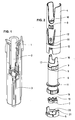
- FIG. 1 is shown for better understanding of the relationship of the front part 1 of an autoinjector with syringe 2 received therein.
- the front part 1 is assembled before use of the autoinjector by means of a bayonet-type connection with a drive part, not shown, which contains the necessary elements for the automatic execution of an injection, in particular springs.
- the injection needle of this syringe 2 is covered in a known manner with a plugged needle cap 3.
- the device according to the invention serves to remove this needle protection cap 3 before using the autoinjector and to replace it after the use of the autoinjector.
- the invention uses the operations of assembling and disassembling the autoinjector before or after the injection.
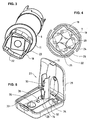
- the in the FIGS. 2 to 5 illustrated device 30 consists of a housing 4, which is closed at the bottom with a housing bottom 5, which is held by latching cams 21 which engage in opening 15 of the housing 4.
- a cam sleeve 6 is rotatably supported, wherein the rotation is limited by arranged on the cam sleeve 6 stops 17, which cooperate with a non-visible in the figures rib in the housing 4.
- a window 8 arranged in the housing 4 releases the view of one of the two, preferably colored, marking areas 9 provided corresponding to the respective rotational position of the cam sleeve 6.
- An inner flange 10 arranged in the upper region of the housing 4 supports the cam sleeve 6 both radially and axially, and an outer flange 11 is provided in the lower region of the cam sleeve 6, with which the cam sleeve 6 is guided radially in the housing 4.
- the cam sleeve has the task of receiving in its interior the front part 1 of an auto-injector. Upwardly projecting tabs 16 and / or provided in the interior of the cam sleeve, not shown ribs provide a rotationally fixed connection between the cam sleeve 6 and the front part 1 of the autoinjector.
- clamping pieces 7 From the housing bottom 5 are four bearing pins 20 upwards, on which four clamping pieces 7 are pivotally mounted. These clamping pieces 7 have the task of grasping and holding the needle cap 3 when the auto-injector is assembled and vice versa to release the needle cap 3 again when the autoinjector is taken apart again for the purpose of removing the spent syringe 2. As FIG. 4 shows, 7 gripping ribs 24 are provided on the clamping pieces, which are pressed into the relatively soft material of the needle cap 3 in order to grip them safely. The movement of the clamping pieces 7 is controlled as follows by a curve part 18 formed at the bottom of the cam sleeve 6.
- a Andschreibkurve 22 which presses the clamping pieces 7 inward when the cam sleeve 6 is rotated clockwise. This is best in FIG. 4 to recognize. If the cam sleeve 6 is rotated in the counterclockwise direction, engages disposed within the Andschreibkurve 22 release cam 23, the best in FIG. 3 can be seen on control pins 19, which are arranged on each clamping piece 7 projecting upward and urges the clamping pieces 7 to the outside.
- the curve part 18 of the cam sleeve 6 is guided with its outer circumference 25 in the housing bottom 5, wherein the housing bottom 5 integrally formed tongues 26 cooperate with the outer region 25 such that the cam sleeve 6 engages in its two rotational end positions.
- the front part 1 of an auto-injector is inserted from above into the cam sleeve 6, and in the front part 1 a syringe filled with an active substance with an injection needle and a needle cap 3 is inserted. Then the drive part of the auto-injector is placed and rotated clockwise.
- the auto-injector is inserted with its front part 1 in the cam sleeve 6, the injection needle slides into the needle cap 3 and the drive part of the autoinjector is rotated counterclockwise to its connection with the front part. 1 to solve.
- the cam sleeve is entrained by this rotation and the release cam 23 ensures that the clamping pieces 7 release the needle cap.
- the syringe 2 can be removed together with the reassembled needle cap 3 from the front part 1.
- FIG. 5 shows a charging station 27 for an auto-injector, in which the device 30 described above is held in the position of use.
- spring tongues 12 are provided with locking lugs 13, which engage in latching recesses 14 which are provided in a receptacle 34 of the charging station 27.
- the charging station is in the example shown at the same time a container consisting of a lower part 28, a lid 29 and a shutter 31.
- the example shown includes a receiving trough 32 for the drive part of the autoinjector, a receiving trough 33 for the device 30, a clamping pin 35 for tensioning the springs of the autoinjector and a further receptacle 36 for a tool such as a key for tightening and loosening a hypodermic needle Luer-Lock.
Landscapes
- Health & Medical Sciences (AREA)
- Engineering & Computer Science (AREA)
- Heart & Thoracic Surgery (AREA)
- Vascular Medicine (AREA)
- Anesthesiology (AREA)
- Biomedical Technology (AREA)
- Environmental & Geological Engineering (AREA)
- Hematology (AREA)
- Life Sciences & Earth Sciences (AREA)
- Animal Behavior & Ethology (AREA)
- General Health & Medical Sciences (AREA)
- Public Health (AREA)
- Veterinary Medicine (AREA)
- Infusion, Injection, And Reservoir Apparatuses (AREA)
Description
- Die Erfindung betrifft eine Vorrichtung zum vorübergehenden Festhalten einer Nadelschutzkappe einer Injektionsvorrichtung, enthaltend ein Gehäuse, einen im Gehäuse angeordneten Aufnahmeteil zur Aufnahme der Injektionsvorrichtung und Haltemittel.
- Bei üblichen, manuell zu betätigenden Injektionsspritzen wird in der Regel die Nadelschutzkappe vor dem Gebrauch von Hand abgenommen und nach dem Gebrauch von Hand wieder aufgesetzt. Gerade beim zuletzt genannten Vorgang besteht für den Benutzer eine erhebliche Verletzungsgefahr durch die gebrauchte Injektionsnadel. Es wurden deshalb schon verschiedene Hilfsmittel zum Abziehen und insbesondere zum Aufsetzen von Nadelschutzkappen vorgeschlagen, die aber allesamt einen separaten Arbeitsschritt erfordern.
- Aus dem Dokument
US 5,356,385 ist ein Halter für Nadelkappen bekannt, bei dem eine Injektionsspritze durch eine Öffnung in ein Haltergehäuse und in dem Gehäuse in einen Greifmechanismus mit einer Drehplatte eingeführt werden kann. Der Greifinechanismus umfasst diverse Klemmelemente, die an der Drehplatte schwenkbar angekoppelt sind. Eine Drehung der Drehplatte bewirkt ein Verschwenken der Klemmelemente. Die Drehplatte ist mittels einer Feder derart vorgespannt, dass sich die Klemmelemente in einer Halteposition zum Halten der Nadelschutzkappe befinden. Um eine Spritze in den Halter einführen zu können, muss vorher manuell ein Arm (60) eingedrückt werden, der die Drehung der Drehplatte derart bewirkt, dass die Klemmelemente von ihrer Halteposition in eine Freigabeposition geschwenkt werden. Beim Lösen des Armes wird die Drehplatte mittels ihrer Vorspannung zurück in die Halteposition gedreht, sodass die Klemmelemente an der Nadelschutzkappe angreifen. Wird nun die Spritze aus dem Halter gezogen, verbleibt die Nadelschutzkappe im Halter, da sie von den Klemmelementen festgehalten wird. - Die Erfindung hat die Aufgabe, eine Vorrichtung vorzuschlagen, mit welcher die Nadelschutzkappe bei einem ohnehin erforderlichen Arbeitsgang zur Vorbereitung einer Injektionsvorrichtung abgezogen und danach auch wieder aufgesetzt werden kann.
- Zur Lösung dieser Aufgabe ist die erfindungsgemässe Vorrichtung dadurch gekennzeichnet, dass der Aufnahmeteil im Gehäuse bewegbar ist, dass in einer ersten Lage des Aufnahmeteils die Haltemittel in einer Freigabeposition sind und dass in einer zweiten Lage des Aufnahmeteils die Haltemittel in einer Halteposition sind.
- Nach einer Ausführungsart der Erfindung ist der Aufnahmeteil durch eine Drehung von seiner ersten Lage in seine zweite Lage bewegbar. Diese Lösung ist insbesondere für Injektionsvorrichtungen vorteilhaft, die zwecks Einsetzens und Entnehmens einer Spritze drehend auseinander genommen werden. Die Haltemittel werden gleichzeitig mit diesem Drehen betätigt.
- Gemäss einer weiteren Ausführungsart der Erfindung sind die Haltemittel als Klemmstücke ausgebildet, die um parallel zur Längsachse der Vorrichtung verlaufende Schwenkachsen gegen die Längsachse hin schwenkbar sind. Dies ermöglicht einen besonders einfachen Aufbau der Vorrichtung. Wenn nach weiteren Ausführungsarten der Erfindung der Aufnahmeteil eine Andrückkurve und gegebenenfalls eine Lösekurve enthält, ergibt sich eine Zwangssteuerung der Klemmteile, was einen besonders sicheren Betrieb der Vorrichtung ermöglicht.
- Nach einer weiteren Ausführungsart der Erfindung sind Anzeigemittel vorgesehen, welche von aussen sichtbar machen, in welcher Drehlage der Aufnahmeteil sich befindet. Die Anzeigemittel enthalten vorzugsweise ein Fenster im Gehäuse, durch welches in jeder Drehlage des Aufnahmeteils ein anderer, an diesem vorhandener Markierbereich sichtbar ist. Diese Massnahmen machen den Betrieb der Vorrichtung noch bequemer und sicherer.
- Ein anderer Aspekt der Erfindung betrifft eine Ladestation für die Vorbereitung einer Injektionsvorrichtung, welche eine erfindungsgemässe Vorrichtung enthält. Dabei kann die Ladestationen noch andere funktionelle Ele- , mente enthalten, die der Vorbereitung einer Injektionsvorrichtung, insbesondere eines Autoinjektors, dienen. Die erfindungsgemässe Vorrichtung ist vorzugsweise herausnehmbar in der Ladestation aufgenommen. Eine besondere Ausführungsart der Ladestation ist gleichzeitig als Behältnis zur Aufbewahrung der Vorrichtung und von Teilen einer Injektionsvorrichtung ausgebildet. Dies ermöglicht dem Benutzer einer Injektionsvorrichtung, die benötigten Einzelteile einfach mit sich zu tragen und übersichtlich aufzubewahren.
- Eine Ausführungsart der Erfindung wird nachfolgend unter Bezugnahme auf die beiliegenden Zeichnungen beispielhaft beschrieben. Es zeigt:
- Figur 1
- eine aufgeschnittene, perspektivische Ansicht des Vorderteils eines Autoinjektors,
- Figur 2
- eine Explosionsansicht eines Ausführungsbeispiels der Erfindung,
- Figur 3
- eine perspektivische Ansicht einer Einzelheit aus
Figur 2 , - Figur 4
- einen Querschnitt durch den unteren Teil der Vorrichtung nach
Figur 2 und - Figur 5
- eine Ladestation mit einer Vorrichtung nach
Figur 2 . - In
Figur 1 ist zum Besseren Verständnis des Zusammenhangs der Vorderteil 1 eines Autoinjektors mit darin aufgenommener Spritze 2 dargestellt. Der Vorderteil 1 wird vor der Verwendung des Autoinjektors mittels einer bajonettartigen Verbindung mit einem nicht dargestellten Antriebsteil zusammengesetzt, der die zur automatischen Ausführung einer Injektion erforderlichen Elemente, insbesondere Federn enthält. Die Injektionsnadel dieser Spritze 2 ist in bekannter Weise mit einer aufgesteckten Nadelschutzkappe 3 abgedeckt. Die erfindungsgemässe Vorrichtung dient dazu, vor der Verwendung des Autoinjektors diese Nadelschutzkappe 3 abzuziehen und sie nach der Verwendung des Autoinjektors wieder aufzusetzen. Dazu nutzt die Erfindung die Vorgänge des Zusammensetzens und Auseinandernehmens des Autoinjektors vor beziehungsweise nach der Injektion. - Die in den
Figuren 2 bis 5 dargestellte Vorrichtung 30 besteht aus einem Gehäuse 4, das unten mit einem Gehäuseboden 5 verschlossen ist, welcher durch Rastnocken 21 gehalten ist, die in Öffnung 15 des Gehäuses 4 eingreifen. Im Gehäuse 4 ist eine Kurvenhülse 6 drehbar gehalten, wobei die Drehbarkeit durch an der Kurvenhülse 6 angeordnete Anschläge 17 begrenzt wird, die mit einer in den Figuren nicht sichtbaren Rippe im Gehäuse 4 zusammenwirken. Ein im Gehäuse 4 angeordnetes Fenster 8 gibt entsprechend der jeweiligen Drehlage der Kurvenhülse 6 den Blick auf einen der beiden an ihr vorgesehenen, vorzugsweise farbigen Markierbereiche 9 frei. Ein im oberen Bereich des Gehäuses 4 angeordneter Innenflansch 10 stützt die Kurvenhülse 6 sowohl radial als auch axial und im unteren Bereich der Kurvenhülse 6 ist ein Aussenflansch 11 vorgesehen, mit dem die Kurvenhülse 6 radial im Gehäuse 4 geführt wird. Die Kurvenhülse hat die Aufgabe, in ihrem Inneren den Vorderteil 1 eines Autoinjektors aufzunehmen. Nach oben ragende Lappen 16 und/oder im Inneren der Kurvenhülse vorgesehene, nicht dargestellte Rippen sorgen für eine drehfeste Verbindung zwischen der Kurvenhülse 6 und dem Vorderteil 1 des Autoinjektors. - Vom Gehäuseboden 5 stehen vier Lagerzapfen 20 nach oben vor, auf denen vier Klemmstücke 7 schwenkbar gelagert sind. Diese Klemmstücke 7 haben die Aufgabe, die Nadelschutzkappe 3 zu ergreifen und festzuhalten, wenn der Autoinjektor zusammengesetzt wird und umgekehrt die Nadelschutzkappe 3 wieder freizugeben, wenn der Autoinjektor zwecks Entnahme der verbrauchten Spritze 2 wieder auseinander genommen wird. Wie
Figur 4 zeigt, sind an den Klemmstücken 7 Greifrippen 24 vorgesehen, welche in das relativ weiche Material der Nadelschutzkappe 3 eingedrückt werden, um diese sicher zu greifen. Die Bewegung der Klemmstücke 7 wird wie folgt durch einen unten an der Kurvenhülse 6 geformten Kurventeil 18 gesteuert. Im Inneren des Kurventeils befindet sich eine Andrückkurve 22, welche die Klemmstücke 7 nach innen drückt, wenn die Kurvenhülse 6 im Uhrzeigersinn gedreht wird. Dies ist am Besten inFigur 4 zu erkennen. Wird die Kurvenhülse 6 im Gegenuhrzeigersinn gedreht, greift eine innerhalb der Andrückkurve 22 angeordnete Lösekurve 23, die am Besten inFigur 3 zu erkennen ist, an Steuerzapfen 19 an, die auf jedem Klemmstück 7 nach oben vorstehend angeordnet sind und drängt die Klemmstücke 7 nach außen. Der Kurventeil 18 der Kurvenhülse 6 ist mit seinem Aussenumfang 25 im Gehäuseboden 5 geführt, wobei am Gehäuseboden 5 angeformte Zungen 26 mit dem Aussenbereich 25 derart zusammenwirken, dass die Kurvenhülse 6 in ihren beiden Dreh-Endlagen einrastet. - Zur Verwendung der Vorrichtung wird diese entweder mit einer Hand festgehalten oder vorteilhafter in eine entsprechende Ladestation 27 eingesetzt, wie dies weiter unten beschrieben wird. Dann wird von oben der Vorderteil 1 eines Autoinjektors in die Kurvenhülse 6 eingesetzt und in den Vorderteil 1 wird eine mit einem Wirkstoff gefüllte Spritze mit Injektionsnadel und Nadelschutzkappe 3 gesteckt. Dann wird der Antriebsteil des Autoinjektors aufgesetzt und im Uhrzeigersinn gedreht. Bei dieser Drehung wird - gleichzeitig oder nacheinander, je nach der zwischen den einzelnen Komponenten wirkenden Reibung - der Antriebsteil des Autoinjektors mit dem Vorderteil 1 über die erwähnte bajonettartige Verbindung gekoppelt und die Kurvenhülse 6 im Gehäuse 4 gedreht, wobei die Klemmstücke 7 durch die Andrückkurve 22 nach innen gedrängt werden und die Nadelschutzkappe 3 zwischen sich festklemmen. Im Fenster 8 ist nun ein anderer, beispielsweise grün gefärbter Bereich 9 sichtbar, der signalisiert, dass der Autoinjektor nun betriebsbereit ist und nach oben herausgezogen werden kann, wobei die Nadelschutzkappe 3 zwischen den Klemmstücken 7 verbleibt. Nach der Injektion spielt sich das Ganze in umgekehrter Reihenfolge ab, der Autoinjektor wird mit seinem Vorderteil 1 in die Kurvenhülse 6 gesteckt, die Injektionsnadel schiebt sich in die Nadelschutzkappe 3 und der Antriebsteil des Autoinjektors wird im Gegenuhrzeigersinn gedreht, um seine Verbindung mit dem Vorderteil 1 zu lösen. Die Kurvenhülse wird durch diese Drehung mitgenommen und die Lösekurve 23 sorgt dafür, dass die Klemmstücke 7 die Nadelschutzkappe freigeben. Schliesslich kann die Spritze 2 mitsamt der wieder aufgesetzten Nadelschutzkappe 3 aus dem Vorderteil 1 entnommen werden.
-
Figur 5 zeigt eine Ladestation 27 für einen Autoinjektor, in welcher die oben beschriebene Vorrichtung 30 in Gebrauchslage gehalten ist. Im Gehäuse 4 der Vorrichtung sind Federzungen 12 mit Rastnasen 13 vorhanden, welche in Rast-Ausnehmungen 14 einrasten, die in einer Aufnahme 34 der Ladestation 27 vorgesehen sind. Die Ladestation ist im dargestellten Beispiel gleichzeitig ein Behältnis, bestehend aus einem Unterteil 28, einem Deckel 29 und einem Verschluss 31. Neben der beschriebenen Aufnahme 34 für die Vorrichtung 30 enthält das dargestellte Beispiel eine Aufnahmemulde 32 für den Antriebsteil des Autoinjektors, eine Aufnahmemulde 33 für die Vorrichtung 30, einen Spannzapfen 35 zum Spannen der Federn des Autoinjektors und eine weitere Aufnahme 36 für ein Werkzeug wie einen Schlüssel zum Anziehen und Lösen einer Injektionsnadel des Typs Luer-Lock.
Claims (11)
- Vorrichtung zum vorübergehenden Festhalten einer Nadelschutzkappe (3) einer Injektionsnadel einer Injektionsvorrichtung, enthaltend ein Gehäuse (4), einen im Gehäuse (4) angeordneten Aufnahmeteil (6) zur Aufnahme der Injektionsvorrichtung und Haltemittel (7), dadurch gekennzeichnet, dass der Aufnahmeteil (6) im Gehäuse (4) durch Drehung der darin aufgenommenen Injektionsvorrichtung bewegbar ist, dass in einer ersten Lage des Aufnahmeteils (6) die Haltemittel (7) in einer Freigabeposition sind und dass in einer zweiten Lage des Aufnahmeteils (6) die Haltemittel (7) in einer Halteposition sind.
- Vorrichtung nach Anspruch 1, dadurch gekennzeichnet, dass die Drehung des Aufnahmeteils (6) eine Zwangssteuerung der Haltemittel (7) bildet.
- Vorrichtung nach Anspruch 1 oder 2, dadurch gekennzeichnet, dass die Haltemittel als Klemmstücke (7) ausgebildet sind, die um parallel zur Längsachse der Vorrichtung verlaufende Schwenkachsen (20) gegen die Längsachse hin schwenkbar sind.
- Vorrichtung nach Anspruch 3, dadurch gekennzeichnet, dass der Aufnahmeteil (6) eine Andrückkurve (22) enthalt, welche in der zweiten Drehlage des Aufnahmeteils (6) die Klemmstücke (7) zur Längsachse der Vorrichtung hin drückt
- Vorrichtung nach Anspruch 3 oder 4, dadurch gekennzeichnet, dass der Aufhahmetell (6) eine Lösekurve (23) enthalt, welche in der ersten Drehlage des Aufnahmeteils (6) die Klemmstücke (7) von der Längsachse der Vorrichtung weg drückt.
- Vorrichtung nach einem der vorangehenden Ansprüche, gekennzeichnet durch Anzeigemittel (8), welche von aussen sichtbar machen, in welcher Drehlage der Aufnahmeteil (6) sich befindet.
- Vorrichtung nach Anspruch 6, dadurch gekennzeichnet, dass die Anzeigemittel ein Fenster (8) im Gehäuse (4) enthalten, durch welches in jeder Drehlage des Aufnahmeteils (6) ein anderer, an diesem vorhandener Markierbereich (9) sichtbar ist.
- Ladestation (27) für die Vorbereitung einer Injektionsvorrichtung, dadurch gekennzeichnet, dass sie eine Vorrichtung (30) nach einem der vorangehenden Ansprüche enthält.
- Ladestation nach Anspruch 8, dadurch gekennzeichnet, dass die Vorrichtung (30) herausnehmbar in der Ladestation (27) aufgenommen ist.
- Ladestation nach Anspruch 8 oder 9, dadurch gekennzeichnet, dass sie als Behältnis (28, 29) zur Aufbewahrung von Teilen einer Injektionsvorrichtung ausgebildet ist.
- Ladestation nach einem der Ansprüche 8 bis 10, dadurch gekennzeichnet, dass der Aufnahmeteil (6) zum Einsetzen eines Vorderteils (1) eines Autoinjektors ausgebildet ist, ein Antriebsteil des Autoinjektors mit dem Vorderteil (1) koppelbar ist, wobei durch Drehung des Antriebsteils die Kopplung und die Drehung des Aufnahmeteils (6) vermittelbar ist.
Applications Claiming Priority (3)
| Application Number | Priority Date | Filing Date | Title |
|---|---|---|---|
| CH198502 | 2002-11-25 | ||
| CH19852002 | 2002-11-25 | ||
| PCT/CH2003/000756 WO2004047896A1 (de) | 2002-11-25 | 2003-11-17 | Vorrichtung zum vorrübergehenden festhalten einer nadelschutzkappe einer injektionsvorrichtung |
Publications (2)
| Publication Number | Publication Date |
|---|---|
| EP1567209A1 EP1567209A1 (de) | 2005-08-31 |
| EP1567209B1 true EP1567209B1 (de) | 2009-01-21 |
Family
ID=32331827
Family Applications (1)
| Application Number | Title | Priority Date | Filing Date |
|---|---|---|---|
| EP03811706A Expired - Lifetime EP1567209B1 (de) | 2002-11-25 | 2003-11-17 | Vorrichtung zum vorrübergehenden festhalten einer nadelschutzkappe einer injektionsvorrichtung |
Country Status (8)
| Country | Link |
|---|---|
| US (1) | US7370759B2 (de) |
| EP (1) | EP1567209B1 (de) |
| JP (1) | JP4568117B2 (de) |
| CN (1) | CN100415315C (de) |
| AT (1) | ATE421345T1 (de) |
| AU (1) | AU2003275894B2 (de) |
| DE (1) | DE50311134D1 (de) |
| WO (1) | WO2004047896A1 (de) |
Cited By (1)
| Publication number | Priority date | Publication date | Assignee | Title |
|---|---|---|---|---|
| EP2500053A1 (de) | 2011-03-15 | 2012-09-19 | Sanofi-Aventis Deutschland GmbH | Nadelanordnungsspeichervorrichtung |
Families Citing this family (40)
| Publication number | Priority date | Publication date | Assignee | Title |
|---|---|---|---|---|
| US7708718B2 (en) * | 2006-03-17 | 2010-05-04 | Zehner John A | Syringe shield |
| FR2899482A1 (fr) * | 2006-04-11 | 2007-10-12 | Becton Dickinson France Soc Pa | Dispositif d'injection automatique |
| CA2719110C (en) | 2008-03-13 | 2017-07-25 | Becton, Dickinson And Company | Safety needle assembly |
| US8801673B2 (en) | 2008-03-13 | 2014-08-12 | Becton Dickinson & Company | Safety pen needle assembly having shield for non-patient end |
| EP2262558B1 (de) | 2008-03-13 | 2016-11-16 | Becton, Dickinson and Company | Sicherheits-pen-nadelanordnung mit abschirmung für das patientenseitige und das patientenabseitige ende |
| US8052645B2 (en) | 2008-07-23 | 2011-11-08 | Avant Medical Corp. | System and method for an injection using a syringe needle |
| US8177749B2 (en) | 2008-05-20 | 2012-05-15 | Avant Medical Corp. | Cassette for a hidden injection needle |
| JP5836120B2 (ja) | 2008-05-20 | 2015-12-24 | アヴァント・メディカル・コーポレーション | オートインジェクタシステム |
| JP6038884B2 (ja) | 2011-04-20 | 2016-12-07 | アムゲン・インコーポレーテッド | 自動式注射装置 |
| WO2013069209A1 (ja) * | 2011-11-10 | 2013-05-16 | パナソニック株式会社 | 製剤シリンジユニット用保管ケース |
| JP6254149B2 (ja) * | 2012-04-13 | 2017-12-27 | ベクトン・ディキンソン・アンド・カンパニーBecton, Dickinson And Company | ニードルを自動で後退させるマイクロインフューザ |
| USD808010S1 (en) | 2012-04-20 | 2018-01-16 | Amgen Inc. | Injection device |
| USD898908S1 (en) | 2012-04-20 | 2020-10-13 | Amgen Inc. | Pharmaceutical product cassette for an injection device |
| US20140264205A1 (en) * | 2013-03-15 | 2014-09-18 | Morris Elijah Worden | Systems and methods for recharging an auto-injector |
| JP6768501B2 (ja) | 2013-03-15 | 2020-10-14 | アムゲン・インコーポレーテッド | 薬物カセット、自動注入機、および自動注入機システム |
| JP6336564B2 (ja) | 2013-03-15 | 2018-06-06 | アムゲン・インコーポレーテッド | 薬物カセット、自動注入器、および自動注入器システム |
| EP2883562B1 (de) | 2013-12-10 | 2016-08-17 | Becton Dickinson and Company | Passive Sicherheitsstiftnadelanordnung |
| US9649452B2 (en) | 2013-12-10 | 2017-05-16 | Becton, Dickinson And Company | Active safety pen needle assembly |
| KR101489679B1 (ko) | 2014-07-11 | 2015-02-04 | 주식회사 헤즈테크놀로지 | 휴대용 니들 제거기 |
| US9333289B1 (en) | 2015-01-16 | 2016-05-10 | Plas-Tech Engineering, Inc. | Tamper evident closure container |
| USD819198S1 (en) | 2016-04-28 | 2018-05-29 | Amgen Inc. | Autoinjector with removable cap |
| US11173253B2 (en) | 2016-12-12 | 2021-11-16 | Becton, Dickinson And Company | Packaging for safety needle |
| US10729843B2 (en) | 2016-12-12 | 2020-08-04 | Becton, Dickinson And Company | Dual packaging for fill needle and safety needle |
| US11147910B2 (en) | 2016-12-12 | 2021-10-19 | Becton, Dickinson And Company | Packaging for safety needle |
| US11103651B2 (en) | 2016-12-13 | 2021-08-31 | Beckon, Dickinson and Company | Safety needle devices |
| US20180161491A1 (en) * | 2016-12-12 | 2018-06-14 | Becton, Dickinson And Company | Packaging For Safety Needle |
| US10589036B2 (en) | 2016-12-13 | 2020-03-17 | Becton, Dickinson And Company | Safety needle device |
| US10661026B2 (en) | 2016-12-13 | 2020-05-26 | Becton, Dickinson And Company | Safety needle device |
| US10792439B2 (en) | 2016-12-13 | 2020-10-06 | Becton, Dickinson And Company | Safety needle devices |
| US10265471B2 (en) | 2017-08-30 | 2019-04-23 | Pirouette Medical LLC | Compact auto-injector |
| US10441714B2 (en) | 2017-10-05 | 2019-10-15 | Pirouette Medical LLC | Protective case for an auto-injector |
| USD1010811S1 (en) | 2019-09-30 | 2024-01-09 | Amgen Inc. | Handheld drug delivery device |
| JP2021500644S (ja) | 2020-11-05 | 2022-12-27 | 注射器 | |
| USD974547S1 (en) | 2020-11-05 | 2023-01-03 | Amgen Inc. | Handheld drug delivery device |
| USD973866S1 (en) | 2020-11-05 | 2022-12-27 | Amgen Inc. | Handheld drug delivery device |
| JP1708399S (ja) * | 2021-02-16 | 2022-02-25 | ニードルガイド装置ハウジング | |
| USD985116S1 (en) | 2021-03-10 | 2023-05-02 | Amgen Inc. | Handheld drug delivery device |
| USD985117S1 (en) | 2021-03-10 | 2023-05-02 | Amgen Inc. | Handheld drug delivery device |
| USD985118S1 (en) | 2021-03-10 | 2023-05-02 | Amgen Inc. | Handheld drug delivery device |
| USD985119S1 (en) | 2021-03-30 | 2023-05-02 | Amgen Inc. | Handheld drug delivery device |
Family Cites Families (8)
| Publication number | Priority date | Publication date | Assignee | Title |
|---|---|---|---|---|
| US4915233A (en) * | 1988-11-02 | 1990-04-10 | The Regents Of The University Of California | Dental anesthesia organizer |
| IT1265322B1 (it) * | 1993-01-29 | 1996-10-31 | Claudio Latini | Dispositivo per prevenire punture accidentali. |
| FR2714836B1 (fr) * | 1994-01-11 | 1996-03-29 | Henry Abrard | Dispositif pour extraire automatiquement l'aiguille d'une seringue à usage médical ou paramédical et, notamment à usage dentaire. |
| DE29608141U1 (de) * | 1996-05-04 | 1996-08-01 | Kann Hildegard Van | Entsorgungsgerät zur Entfernung gebrauchter Kanülen, insbesondere Einwegkanülen |
| JPH10127709A (ja) * | 1996-10-25 | 1998-05-19 | Dental Act:Kk | 注射針脱離処分装置 |
| NL1006153C2 (nl) * | 1997-05-29 | 1998-12-01 | Medical Service Kronenburg | Apparaat voor het losdraaien van gebruikte medische naalden. |
| CN2355722Y (zh) * | 1998-12-08 | 1999-12-29 | 茂欣厦门工业有限公司 | 针头的拔取装置 |
| JP3002198B1 (ja) * | 1999-03-02 | 2000-01-24 | 日本イーライリリー株式会社 | 注射器収納ケ―ス |
-
2003
- 2003-11-17 CN CNB2003801039812A patent/CN100415315C/zh not_active Expired - Fee Related
- 2003-11-17 EP EP03811706A patent/EP1567209B1/de not_active Expired - Lifetime
- 2003-11-17 JP JP2004554138A patent/JP4568117B2/ja not_active Expired - Fee Related
- 2003-11-17 WO PCT/CH2003/000756 patent/WO2004047896A1/de active Application Filing
- 2003-11-17 AU AU2003275894A patent/AU2003275894B2/en not_active Ceased
- 2003-11-17 DE DE50311134T patent/DE50311134D1/de not_active Expired - Fee Related
- 2003-11-17 AT AT03811706T patent/ATE421345T1/de not_active IP Right Cessation
-
2005
- 2005-05-19 US US11/132,732 patent/US7370759B2/en not_active Expired - Fee Related
Cited By (3)
| Publication number | Priority date | Publication date | Assignee | Title |
|---|---|---|---|---|
| EP2500053A1 (de) | 2011-03-15 | 2012-09-19 | Sanofi-Aventis Deutschland GmbH | Nadelanordnungsspeichervorrichtung |
| WO2012123354A1 (en) | 2011-03-15 | 2012-09-20 | Sanofi-Aventis Deutschland Gmbh | Needle assembly storage device |
| US9393360B2 (en) | 2011-03-15 | 2016-07-19 | Sanofi-Aventis Deutschland Gmbh | Needle assembly storage device |
Also Published As
| Publication number | Publication date |
|---|---|
| AU2003275894B2 (en) | 2008-04-03 |
| CN100415315C (zh) | 2008-09-03 |
| AU2003275894A1 (en) | 2004-06-18 |
| JP2006507059A (ja) | 2006-03-02 |
| US7370759B2 (en) | 2008-05-13 |
| US20050279664A1 (en) | 2005-12-22 |
| CN1717259A (zh) | 2006-01-04 |
| JP4568117B2 (ja) | 2010-10-27 |
| EP1567209A1 (de) | 2005-08-31 |
| DE50311134D1 (de) | 2009-03-12 |
| WO2004047896A1 (de) | 2004-06-10 |
| ATE421345T1 (de) | 2009-02-15 |
Similar Documents
| Publication | Publication Date | Title |
|---|---|---|
| EP1567209B1 (de) | Vorrichtung zum vorrübergehenden festhalten einer nadelschutzkappe einer injektionsvorrichtung | |
| DE60223045T2 (de) | Schutzschild für Spitze | |
| EP1075292A1 (de) | Injektionsvorrichtung | |
| DE3339832A1 (de) | Elektrisches geraet zum verdampfen von wirkstoffen, insbesondere insektiziden | |
| DE202011109359U1 (de) | Automatische Injektionsspritze | |
| DE102010009186A1 (de) | Magazin für eine Handfeuerwaffe | |
| DE102007002096A1 (de) | Vorrichtung zur Injektion von Flüssigkeiten | |
| DE3207178A1 (de) | Zufuhrrohrschutzvorrichtung mit einer durch eine einzige bewegung betaetigbaren deckelhebeeinrichtung fuer eine nahrungsmittel-behandlungsvorrichtung | |
| DE102007009340A1 (de) | Nadelschutzvorrichtung mit integrierter Nadelträgerentfernungsvorrichtung zum Entfernen eines Nadelträgers von einem Injektionsgerät | |
| DE60222001T2 (de) | Sicherheitsvorrichtung für eine spritze | |
| DE102014119428B4 (de) | Vorrichtung zur Aufnahme von Getränkebehältern | |
| DE1622868A1 (de) | Drehbares Magazin fuer Diapositive | |
| EP1209308B1 (de) | Gelenkhalterung | |
| DE102012112882B4 (de) | Stechhilfe zur Gewinnung von Körperflüssigkeitsproben | |
| DE2216588C3 (de) | Elektrisch angetriebener Dosenöffner | |
| EP0443617A1 (de) | Vorrichtung zum Zentrieren und Ausrichten von Gefässen | |
| DE1039814B (de) | Vorrichtung zum Verriegeln und Loesen von auswechselbaren Nockenscheiben fuer Zickzacknaehmaschinen | |
| EP1321157B1 (de) | Vorrichtung zur Entsorgung einer Kanüle und einer zugehörigen Schutzhülle | |
| DE2029459A1 (de) | Vorrichtung zum Aufbewahren und Einkerben von Anglerbleischrot | |
| EP1438924B1 (de) | Abfallbehälter | |
| EP0073749B1 (de) | Kleinteilbehälter | |
| DE3240572C2 (de) | ||
| DE3516644A1 (de) | Permutationsschloss fuer koffer oder dergleichen | |
| DE4337305C1 (de) | Vorrichtung zum Entfernen einer auf einem Ansatz eines Spritzenkörpers aufgeschraubten Nadel | |
| DE3740229C2 (de) |
Legal Events
| Date | Code | Title | Description |
|---|---|---|---|
| PUAI | Public reference made under article 153(3) epc to a published international application that has entered the european phase |
Free format text: ORIGINAL CODE: 0009012 |
|
| 17P | Request for examination filed |
Effective date: 20050627 |
|
| AK | Designated contracting states |
Kind code of ref document: A1 Designated state(s): AT BE BG CH CY CZ DE DK EE ES FI FR GB GR HU IE IT LI LU MC NL PT RO SE SI SK TR |
|
| AX | Request for extension of the european patent |
Extension state: AL LT LV MK |
|
| DAX | Request for extension of the european patent (deleted) | ||
| 17Q | First examination report despatched |
Effective date: 20071115 |
|
| GRAP | Despatch of communication of intention to grant a patent |
Free format text: ORIGINAL CODE: EPIDOSNIGR1 |
|
| GRAS | Grant fee paid |
Free format text: ORIGINAL CODE: EPIDOSNIGR3 |
|
| GRAA | (expected) grant |
Free format text: ORIGINAL CODE: 0009210 |
|
| AK | Designated contracting states |
Kind code of ref document: B1 Designated state(s): AT BE BG CH CY CZ DE DK EE ES FI FR GB GR HU IE IT LI LU MC NL PT RO SE SI SK TR |
|
| REG | Reference to a national code |
Ref country code: GB Ref legal event code: FG4D Free format text: NOT ENGLISH |
|
| REG | Reference to a national code |
Ref country code: CH Ref legal event code: EP |
|
| REG | Reference to a national code |
Ref country code: IE Ref legal event code: FG4D Free format text: LANGUAGE OF EP DOCUMENT: GERMAN |
|
| REF | Corresponds to: |
Ref document number: 50311134 Country of ref document: DE Date of ref document: 20090312 Kind code of ref document: P |
|
| PG25 | Lapsed in a contracting state [announced via postgrant information from national office to epo] |
Ref country code: NL Free format text: LAPSE BECAUSE OF FAILURE TO SUBMIT A TRANSLATION OF THE DESCRIPTION OR TO PAY THE FEE WITHIN THE PRESCRIBED TIME-LIMIT Effective date: 20090121 |
|
| NLV1 | Nl: lapsed or annulled due to failure to fulfill the requirements of art. 29p and 29m of the patents act | ||
| PG25 | Lapsed in a contracting state [announced via postgrant information from national office to epo] |
Ref country code: ES Free format text: LAPSE BECAUSE OF FAILURE TO SUBMIT A TRANSLATION OF THE DESCRIPTION OR TO PAY THE FEE WITHIN THE PRESCRIBED TIME-LIMIT Effective date: 20090502 Ref country code: SI Free format text: LAPSE BECAUSE OF FAILURE TO SUBMIT A TRANSLATION OF THE DESCRIPTION OR TO PAY THE FEE WITHIN THE PRESCRIBED TIME-LIMIT Effective date: 20090121 Ref country code: FI Free format text: LAPSE BECAUSE OF FAILURE TO SUBMIT A TRANSLATION OF THE DESCRIPTION OR TO PAY THE FEE WITHIN THE PRESCRIBED TIME-LIMIT Effective date: 20090121 |
|
| REG | Reference to a national code |
Ref country code: IE Ref legal event code: FD4D |
|
| PG25 | Lapsed in a contracting state [announced via postgrant information from national office to epo] |
Ref country code: PT Free format text: LAPSE BECAUSE OF FAILURE TO SUBMIT A TRANSLATION OF THE DESCRIPTION OR TO PAY THE FEE WITHIN THE PRESCRIBED TIME-LIMIT Effective date: 20090622 Ref country code: SE Free format text: LAPSE BECAUSE OF FAILURE TO SUBMIT A TRANSLATION OF THE DESCRIPTION OR TO PAY THE FEE WITHIN THE PRESCRIBED TIME-LIMIT Effective date: 20090421 |
|
| PG25 | Lapsed in a contracting state [announced via postgrant information from national office to epo] |
Ref country code: IE Free format text: LAPSE BECAUSE OF FAILURE TO SUBMIT A TRANSLATION OF THE DESCRIPTION OR TO PAY THE FEE WITHIN THE PRESCRIBED TIME-LIMIT Effective date: 20090121 Ref country code: DK Free format text: LAPSE BECAUSE OF FAILURE TO SUBMIT A TRANSLATION OF THE DESCRIPTION OR TO PAY THE FEE WITHIN THE PRESCRIBED TIME-LIMIT Effective date: 20090121 Ref country code: EE Free format text: LAPSE BECAUSE OF FAILURE TO SUBMIT A TRANSLATION OF THE DESCRIPTION OR TO PAY THE FEE WITHIN THE PRESCRIBED TIME-LIMIT Effective date: 20090121 Ref country code: CZ Free format text: LAPSE BECAUSE OF FAILURE TO SUBMIT A TRANSLATION OF THE DESCRIPTION OR TO PAY THE FEE WITHIN THE PRESCRIBED TIME-LIMIT Effective date: 20090121 |
|
| PLBE | No opposition filed within time limit |
Free format text: ORIGINAL CODE: 0009261 |
|
| STAA | Information on the status of an ep patent application or granted ep patent |
Free format text: STATUS: NO OPPOSITION FILED WITHIN TIME LIMIT |
|
| PG25 | Lapsed in a contracting state [announced via postgrant information from national office to epo] |
Ref country code: SK Free format text: LAPSE BECAUSE OF FAILURE TO SUBMIT A TRANSLATION OF THE DESCRIPTION OR TO PAY THE FEE WITHIN THE PRESCRIBED TIME-LIMIT Effective date: 20090121 Ref country code: RO Free format text: LAPSE BECAUSE OF FAILURE TO SUBMIT A TRANSLATION OF THE DESCRIPTION OR TO PAY THE FEE WITHIN THE PRESCRIBED TIME-LIMIT Effective date: 20090121 |
|
| 26N | No opposition filed |
Effective date: 20091022 |
|
| PG25 | Lapsed in a contracting state [announced via postgrant information from national office to epo] |
Ref country code: BG Free format text: LAPSE BECAUSE OF FAILURE TO SUBMIT A TRANSLATION OF THE DESCRIPTION OR TO PAY THE FEE WITHIN THE PRESCRIBED TIME-LIMIT Effective date: 20090421 |
|
| BERE | Be: lapsed |
Owner name: TECPHARMA LICENSING A.G. Effective date: 20091130 |
|
| PG25 | Lapsed in a contracting state [announced via postgrant information from national office to epo] |
Ref country code: MC Free format text: LAPSE BECAUSE OF NON-PAYMENT OF DUE FEES Effective date: 20091130 |
|
| REG | Reference to a national code |
Ref country code: CH Ref legal event code: PL |
|
| GBPC | Gb: european patent ceased through non-payment of renewal fee |
Effective date: 20091117 |
|
| REG | Reference to a national code |
Ref country code: FR Ref legal event code: ST Effective date: 20100730 |
|
| PG25 | Lapsed in a contracting state [announced via postgrant information from national office to epo] |
Ref country code: CH Free format text: LAPSE BECAUSE OF NON-PAYMENT OF DUE FEES Effective date: 20091130 Ref country code: LI Free format text: LAPSE BECAUSE OF NON-PAYMENT OF DUE FEES Effective date: 20091130 Ref country code: BE Free format text: LAPSE BECAUSE OF NON-PAYMENT OF DUE FEES Effective date: 20091130 Ref country code: FR Free format text: LAPSE BECAUSE OF NON-PAYMENT OF DUE FEES Effective date: 20091130 Ref country code: GR Free format text: LAPSE BECAUSE OF FAILURE TO SUBMIT A TRANSLATION OF THE DESCRIPTION OR TO PAY THE FEE WITHIN THE PRESCRIBED TIME-LIMIT Effective date: 20090422 |
|
| PG25 | Lapsed in a contracting state [announced via postgrant information from national office to epo] |
Ref country code: DE Free format text: LAPSE BECAUSE OF NON-PAYMENT OF DUE FEES Effective date: 20100601 |
|
| PG25 | Lapsed in a contracting state [announced via postgrant information from national office to epo] |
Ref country code: GB Free format text: LAPSE BECAUSE OF NON-PAYMENT OF DUE FEES Effective date: 20091117 |
|
| PG25 | Lapsed in a contracting state [announced via postgrant information from national office to epo] |
Ref country code: AT Free format text: LAPSE BECAUSE OF NON-PAYMENT OF DUE FEES Effective date: 20091117 |
|
| PG25 | Lapsed in a contracting state [announced via postgrant information from national office to epo] |
Ref country code: IT Free format text: LAPSE BECAUSE OF FAILURE TO SUBMIT A TRANSLATION OF THE DESCRIPTION OR TO PAY THE FEE WITHIN THE PRESCRIBED TIME-LIMIT Effective date: 20090121 |
|
| PG25 | Lapsed in a contracting state [announced via postgrant information from national office to epo] |
Ref country code: LU Free format text: LAPSE BECAUSE OF NON-PAYMENT OF DUE FEES Effective date: 20091117 |
|
| PG25 | Lapsed in a contracting state [announced via postgrant information from national office to epo] |
Ref country code: HU Free format text: LAPSE BECAUSE OF FAILURE TO SUBMIT A TRANSLATION OF THE DESCRIPTION OR TO PAY THE FEE WITHIN THE PRESCRIBED TIME-LIMIT Effective date: 20090722 |
|
| PG25 | Lapsed in a contracting state [announced via postgrant information from national office to epo] |
Ref country code: TR Free format text: LAPSE BECAUSE OF FAILURE TO SUBMIT A TRANSLATION OF THE DESCRIPTION OR TO PAY THE FEE WITHIN THE PRESCRIBED TIME-LIMIT Effective date: 20090121 |
|
| PG25 | Lapsed in a contracting state [announced via postgrant information from national office to epo] |
Ref country code: CY Free format text: LAPSE BECAUSE OF FAILURE TO SUBMIT A TRANSLATION OF THE DESCRIPTION OR TO PAY THE FEE WITHIN THE PRESCRIBED TIME-LIMIT Effective date: 20090121 |