EP1566907B1 - Système et procédé de communication, dispositif d'emission, dispositif de réception et programme de commande - Google Patents
Système et procédé de communication, dispositif d'emission, dispositif de réception et programme de commande Download PDFInfo
- Publication number
- EP1566907B1 EP1566907B1 EP20030774092 EP03774092A EP1566907B1 EP 1566907 B1 EP1566907 B1 EP 1566907B1 EP 20030774092 EP20030774092 EP 20030774092 EP 03774092 A EP03774092 A EP 03774092A EP 1566907 B1 EP1566907 B1 EP 1566907B1
- Authority
- EP
- European Patent Office
- Prior art keywords
- symbol
- information
- unit
- frequency bandwidth
- symbol length
- Prior art date
- Legal status (The legal status is an assumption and is not a legal conclusion. Google has not performed a legal analysis and makes no representation as to the accuracy of the status listed.)
- Expired - Fee Related
Links
Images


Classifications
-
- H—ELECTRICITY
- H04—ELECTRIC COMMUNICATION TECHNIQUE
- H04L—TRANSMISSION OF DIGITAL INFORMATION, e.g. TELEGRAPHIC COMMUNICATION
- H04L27/00—Modulated-carrier systems
- H04L27/26—Systems using multi-frequency codes
- H04L27/2601—Multicarrier modulation systems
- H04L27/2602—Signal structure
-
- H—ELECTRICITY
- H04—ELECTRIC COMMUNICATION TECHNIQUE
- H04L—TRANSMISSION OF DIGITAL INFORMATION, e.g. TELEGRAPHIC COMMUNICATION
- H04L27/00—Modulated-carrier systems
- H04L27/26—Systems using multi-frequency codes
- H04L27/2601—Multicarrier modulation systems
- H04L27/2626—Arrangements specific to the transmitter only
-
- H—ELECTRICITY
- H04—ELECTRIC COMMUNICATION TECHNIQUE
- H04L—TRANSMISSION OF DIGITAL INFORMATION, e.g. TELEGRAPHIC COMMUNICATION
- H04L27/00—Modulated-carrier systems
- H04L27/26—Systems using multi-frequency codes
- H04L27/2601—Multicarrier modulation systems
- H04L27/2647—Arrangements specific to the receiver only
- H04L27/2655—Synchronisation arrangements
- H04L27/2656—Frame synchronisation, e.g. packet synchronisation, time division duplex [TDD] switching point detection or subframe synchronisation
-
- H—ELECTRICITY
- H04—ELECTRIC COMMUNICATION TECHNIQUE
- H04L—TRANSMISSION OF DIGITAL INFORMATION, e.g. TELEGRAPHIC COMMUNICATION
- H04L27/00—Modulated-carrier systems
- H04L27/26—Systems using multi-frequency codes
- H04L27/2601—Multicarrier modulation systems
- H04L27/2647—Arrangements specific to the receiver only
- H04L27/2655—Synchronisation arrangements
- H04L27/2662—Symbol synchronisation
-
- H—ELECTRICITY
- H04—ELECTRIC COMMUNICATION TECHNIQUE
- H04L—TRANSMISSION OF DIGITAL INFORMATION, e.g. TELEGRAPHIC COMMUNICATION
- H04L27/00—Modulated-carrier systems
- H04L27/26—Systems using multi-frequency codes
- H04L27/2601—Multicarrier modulation systems
- H04L27/2647—Arrangements specific to the receiver only
- H04L27/2655—Synchronisation arrangements
- H04L27/2668—Details of algorithms
- H04L27/2681—Details of algorithms characterised by constraints
- H04L27/2688—Resistance to perturbation, e.g. noise, interference or fading
-
- H—ELECTRICITY
- H04—ELECTRIC COMMUNICATION TECHNIQUE
- H04B—TRANSMISSION
- H04B1/00—Details of transmission systems, not covered by a single one of groups H04B3/00 - H04B13/00; Details of transmission systems not characterised by the medium used for transmission
- H04B1/69—Spread spectrum techniques
- H04B1/707—Spread spectrum techniques using direct sequence modulation
- H04B1/7097—Interference-related aspects
- H04B1/7103—Interference-related aspects the interference being multiple access interference
-
- H—ELECTRICITY
- H04—ELECTRIC COMMUNICATION TECHNIQUE
- H04L—TRANSMISSION OF DIGITAL INFORMATION, e.g. TELEGRAPHIC COMMUNICATION
- H04L27/00—Modulated-carrier systems
- H04L27/26—Systems using multi-frequency codes
- H04L27/2601—Multicarrier modulation systems
- H04L27/2602—Signal structure
- H04L27/2605—Symbol extensions, e.g. Zero Tail, Unique Word [UW]
- H04L27/2607—Cyclic extensions
-
- H—ELECTRICITY
- H04—ELECTRIC COMMUNICATION TECHNIQUE
- H04L—TRANSMISSION OF DIGITAL INFORMATION, e.g. TELEGRAPHIC COMMUNICATION
- H04L27/00—Modulated-carrier systems
- H04L27/26—Systems using multi-frequency codes
- H04L27/2601—Multicarrier modulation systems
- H04L27/2602—Signal structure
- H04L27/261—Details of reference signals
- H04L27/2613—Structure of the reference signals
-
- H—ELECTRICITY
- H04—ELECTRIC COMMUNICATION TECHNIQUE
- H04L—TRANSMISSION OF DIGITAL INFORMATION, e.g. TELEGRAPHIC COMMUNICATION
- H04L5/00—Arrangements affording multiple use of the transmission path
- H04L5/003—Arrangements for allocating sub-channels of the transmission path
- H04L5/0044—Arrangements for allocating sub-channels of the transmission path allocation of payload
Definitions
- the present invention relates to a communications system and a communications method in which the same frequency bandwidth is used by a plurality of transmission methods, a transmitting apparatus, a receiving apparatus and a control program.
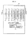
- Fig. 1A shows a transmitting apparatus 100 which can support the conventional OFDM method
- Fig. 1B shows a receiving apparatus 200 which can support the conventional OFDM method.
- the transmitting apparatus 100 includes a coder 101, an interleaver 102, a symbol mapper 103, a serial-parallel converting unit (S/P) 104, an inverse fast Fourier transforming unit (IFFT) 105, a parallel-serial converting unit (P/S) 106, an insertion circuit 107 and a transmitting unit 108.
- S/P serial-parallel converting unit
- IFFT inverse fast Fourier transforming unit
- P/S parallel-serial converting unit
- the coder 101 is configured to perform an error correction coding process on input bit streams.
- the interleaver 102 is configured to perform an interleaving process on the bit streams output from the coder 101.
- the symbol mapper 103 is configured to map the input bit streams into symbols.
- the serial-parallel converting unit 104 is configured to perform a serial-parallel converting process on the symbols output from the symbol mapper 103.
- the inverse fast Fourier transforming unit 105 is configured to perform an inverse fast Fourier transforming process on the parallel symbols output from the serial-parallel converting unit 104.
- the parallel-serial converting unit 106 is configured to perform a parallel-serial converting process on the parallel symbols output from the inverse fast Fourier transforming unit 105.
- the insertion circuit 107 is configured to generate OFDM signals into which guard intervals (GI) are inserted, from the serial symbols output from the parallel-serial converting unit 106.
- the transmitting unit 108 is configured to transmit the OFDM signals output from the insertion circuit 107.
- the receiving apparatus 200 includes a receiving unit 201, a removal circuit 202, a serial-parallel converting unit (S/P) 203, a fast Fourier transforming unit (FFT) 204, a parallel-serial converting unit (P/S) 205, a symbol demapper 206, a deinterleaver 207 and a decoder 208.
- S/P serial-parallel converting unit
- FFT fast Fourier transforming unit
- P/S parallel-serial converting unit
- the removal circuit 202 is configured to remove the guard intervals from the OFDM signals received by the receiving unit 201.
- the serial-parallel converting unit 203 is configured to perform a serial-parallel converting process on serial sample values of the OFDM signals output from the removal circuit 202.
- the fast Fourier transforming unit 204 is configured to perform a fast Fourier transforming process on the parallel sample values output from the serial-parallel converting unit 203.
- the parallel-serial converting unit 205 is configured to perform a parallel-serial converting process on the parallel symbols output from the fast Fourier transforming unit 204.
- the serial symbols output from the parallel-serial converting unit 205 are output as the bit streams input in the transmitting apparatus 100, via the symbol demapper 206, the deinterleaver 207 and the decoder 208.
- Fig. 2 shows a structure of an OFDM signal transmitted in the conventional OFDM method.
- the receiving apparatus 200 can separate and demodulate the modification signals of the respective sub-carriers by the fast Fourier transforming process.
- the serial-parallel converting unit 104 performs the serial-parallel converting process so that the output corresponding to the frequency f 3 becomes zero.
- the conventional receiving apparatus 200 demodulates the received OFDM signals using the fast Fourier transforming process.
- the symbol length in the own system is different from the symbol length in the different system, which are mixed in the same frequency bandwidth, two symbols of the different system are included within one OFDM symbol interval in the received OFDM signals.
- OFDM symbols S 33 and S 34 of the different system are included in the OFDM symbol interval T of the own system which includes OFDM symbols S 04 , S 14 , S 24 and S 44 .
- the OFDM symbol interval T means a length of an OFDM symbol to which a guard interval has been added.
- VSF-OFCDM Very Spreading Factor-Orthogonal Frequency and Code Division Multiplexing
- symbols are separated onto a plurality of frequency axes and the symbols are spread with a spreading code having a variable spreading factor assigned to each mobile station for transmission. Therefore, a symbol length which is different from a symbol length of a different conventional system (transmission method) is used.
- transmission method transmission method
- the present invention has been made in view of the above, and has an object of providing a communications system and a communications method which can reduce the influence of interference from other systems which results from a difference in symbol length, in an area where a plurality of systems using different transmission methods are mixed, a transmitting apparatus, a receiving apparatus and a control program.
- a first aspect of the present invention is summarized as a communications system in which a plurality of systems share a frequency bandwidth to transmit information symbols; wherein one of the plurality of systems includes: an identifying unit configured to identify a first symbol length of an information symbol transmitted in a different system; and an adjusting unit configured to adjust a second symbol length of an information symbol to be transmitted in the one of the plurality of systems, in accordance with the identified first symbol length.
- a second aspect of the present invention is summarized as a communications method in which a plurality of systems share a frequency bandwidth to transmit information symbols, including steps of: identifying, in one of the plurality of systems, a first symbol length of an information symbol transmitted in a different system; and adjusting, in the one of the plurality of systems, a second symbol length of an information symbol to be transmitted, in accordance with the identified first symbol length.
- a third aspect of the present invention is summarized as a transmitting apparatus being operated in a communications system in which a plurality of systems share a frequency bandwidth to transmit information symbols, including: an identifying unit configured to identify a first symbol length of an information symbol transmitted in a different system; and an adjusting unit configured to adjust a second symbol length of an information symbol to be transmitted in the one of the plurality of systems, in accordance with the identified first symbol length.
- the identifying unit can be configured to identify a transmission timing of the information symbol in the different system; and the adjusting unit can be configured to adjust a transmission timing of the information symbol to be transmitted in the one of the plurality of systems, in accordance with an identified transmission timing.
- the transmitting apparatus can be configured to transmit the information symbols using an OFDM orthogonal frequency division multiplexing method; the transmitting apparatus can include a spreading unit configured to spread the information symbol to be transmitted, with a spreading code assigned to a receiving apparatus; and the adjusting unit can be configured to adjust the symbol length of a spread information symbol, in accordance with the identified symbol length.
- the adjusting unit is configured to adjust the symbol length of the information symbol to be transmitted, by adding a symbol length adjustment signal to the information symbol so that an effective symbol interval of the information symbol is set in the middle of a symbol interval of the information symbol.
- the transmitting apparatus can be configured to transmit the information symbols with using an OFDM orthogonal frequency division multiplexing method; and a part of the symbol length adjustment signal or the whole of the symbol length adjustment signal can constitute a guard interval.
- the adjusting unit can be configured to adjust the symbol length of the information symbol to be transmitted so that the symbol length of the information symbol becomes a nonnegative integral multiple or a nonnegative integral submultiple of a detected symbol length.
- the transmitting apparatus can be configured to transmit the information symbols using an OFDM orthogonal frequency division multiplexing method; the identifying unit can be configured to identify a frequency bandwidth used in the different system; and the adjusting unit can be configured to adjust so as not to use an identified frequency bandwidth and a frequency bandwidth adjacent to the identified frequency bandwidth for transmission of the information symbol.
- the transmitting apparatus can include a pilot multiplexing unit configured to multiplex a pilot symbol into the sub-carrier selected by a sub-carrier mapping unit, based on the usage carrier information from the identifying unit.
- the pilot multiplexing unit can be configured to multiplex the pilot symbol to a sub-carrier which is associated with a frequency bandwidth adjacent to a frequency bandwidth not to be used for the transmission of the information symbol.
- the transmitting apparatus can be configured to transmit the information symbols using an OFDM method; and the identifying unit can be configured to judge that a frequency bandwidth associated with a sub-carrier in a reception signal from the different system is used in the different system, when a power level of a signal component of the sub-carrier is larger than a predetermined threshold.
- a fourth aspect of the present invention is summarized as a receiving apparatus to be operated in a communications system according to the first aspect in which a plurality of systems share a frequency bandwidth to transmit information symbols, including: a receiving unit configured to receive information signals in one of the plurality of systems; an identifying unit configured to identify a symbol length of an information symbol transmitted in a different system; and an adjusting unit configured to remove a symbol length adjustment signal from a received information symbol, in accordance with an identified symbol length; and an interference canceller configured to generate a replica of the information signal received from the different system, and to substract the replica from the information signal received by the receiving unit.
- the receiving apparatus can be configured to receive th information symbols transmitted using an OFDM orthogonal frequency division multiplexing method; and the identifying unit can be configured to identify a frequency bandwidth used in one of the plurality of systems to which the receiving apparatus belongs, based on information on a frequency bandwidth associated with a sub-carrier in which a power level of a received signal component is smaller than or equal to a predetermined threshold and information on a frequency bandwidth used in the different system.
- the receiving apparatus can be configured to receive the information symbols transmitted using an OFDM orthogonal frequency division multiplexing method; and the receiving apparatus can include: a power detecting unit configured to detect a frequency bandwidth associated with a sub-carrier in which a power level of a received signal component is larger than or equal to a predetermined threshold; and a collision detecting unit configured to detect a collision of signals in the same frequency bandwidth, based on a frequency bandwidth used in the different system which is identified by the identifying unit and the frequency bandwidth detected by the power detecting unit.
- the receiving apparatus can be configured to receive the information symbols transmitted using an OFDM orthogonal frequency division multiplexing method; and the receiving apparatus can include: a power detecting unit configured to detect a frequency bandwidth associated with a sub-carrier in which a power level of a received signal component is smaller than or equal to a predetermined threshold; and a non-usage frequency bandwidth detecting unit configured to detect a frequency bandwidth which is not used in one of the plurality of systems to which the receiving apparatus belongs and the different system, based on a frequency bandwidth used in the different system which is identified by the identifying unit and the frequency bandwidth detected by the power detecting unit.
- a power detecting unit configured to detect a frequency bandwidth associated with a sub-carrier in which a power level of a received signal component is smaller than or equal to a predetermined threshold
- a non-usage frequency bandwidth detecting unit configured to detect a frequency bandwidth which is not used in one of the plurality of systems to which the receiving apparatus belongs and the different system, based on a frequency bandwidth used in the different system which is identified
- the receiving apparatus can be configured to receive the information symbols transmitted using an OFDM orthogonal frequency division multiplexing method; and the identifying unit can be configured to identify a frequency bandwidth used in one of the plurality of systems to which the receiving apparatus belongs, based on a reception power of a sub-carrier in an interval preceding a head of an OFDM frame.
- a fifth aspect of the present invention is summarized as a control program which controls a transmitting apparatus belonging to one of a plurality of systems, the transmission apparatus being operated in a communications system in which the plurality of systems share a frequency bandwidth to transmit information symbols; wherein the control program is directly loadable into an internal memory of the transmitting apparatus and comprising software code portions for performing the steps: identifying a first symbol length of an information symbol transmitted in a different system; and notifying the transmitting apparatus of a symbol length adjustment signal to be added to an information symbol to be transmitted, so as to adjust a second symbol length of the information symbol, in accordance with the identified symbol length.
- Fig. 3 is a schematic configuration diagram showing the whole configuration of a communications system according to each embodiment of the present invention to be described later.
- the communications system includes base stations 100a, 100b which perform radio communications with different transmission methods, and a mobile station 200 which can perform radio communications with the base stations 100.
- a cell "a" covered by the base station 100a is overlapped with a cell "b" covered by the base station 100b.
- a system 1 to which the base station 100a belongs and a system 2 to which the base station 100b belongs perform radio communications, sharing the same frequency bandwidth and using different transmission method, in the area where the two cells are overlapped.
- the base station 100a is an example of the transmitting apparatus according to the present invention
- the mobile station 200 is an example of the receiving apparatus according to the present invention.
- the system 1 is an "own system”
- the system 2 is a "different system”.
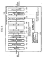
- Fig. 4 shows a transmitting apparatus 100 according to this embodiment
- Fig. 5 shows a receiving apparatus 200 according to this embodiment.
- the difference between the transmitting apparatus 100 and the receiving apparatus 200 according to the first embodiment and those according to the prior art will be described mainly.
- the transmitting apparatus 100 includes a coder 101, an interleaver 102, a symbol mapper 103, a center frequency selecting unit 121, a symbol length adjusting unit 122, a transmission timing adjusting unit 123, a transmitting unit 108 and a transmission method identifying unit 109.
- the center frequency selecting unit 121 is configured to receive "usage carrier information" showing frequency bandwidths of carriers used in the system 2 (the different system) from the transmission method identifying unit 109, to select a frequency bandwidth which is not used in the system 2 based on the usage carrier information, and to perform a primary modulation using a predetermined modulation method on the information symbols from the coder 103.
- the center frequency selecting unit 121 can select a specific frequency bandwidth by using a conventional channel assignment algorithm, when a plurality of frequency bandwidths are not used in the system 2.
- the symbol length adjusting unit 122 is configured to receive "symbol length information" showing the symbol length of an information symbol transmitted in the system 2 from the transmission method identifying unit 109, and to adjust the symbol length of an information symbol to be transmitted, based on the symbol length information.
- the symbol length adjusting unit 122 can adjust the symbol length of the information symbol, by adding a symbol length adjustment signal to the information symbol.
- the transmission timing adjusting unit 123 is configured to receive "transmission timing information (e.g., clock information of the system 2) " showing a transmission timing of an information symbol in the system 2, and to adjust a transmission timing of an information symbol to be transmitted, based on the transmission timing information.
- transmission timing information e.g., clock information of the system 2
- the transmission method identifying unit 109 is configured to identify a plurality of transmission methods mixed in the cell "a" which is covered by the transmitting apparatus (base station) 100a, and to communicate the result to the center frequency selecting unit 121, the symbol length adjusting unit 122, the transmission timing adjusting unit 123 and so on. More specifically, the transmission method identifying unit 109 identifies the usage carrier information, the symbol length information, the transmission timing information and so on, as a transmission method.
- the plurality of transmission methods can be identified by control information (reception signal) received from the system 2, or may set in advance.
- the transmitting apparatus 100 can belong to two ore more systems, and can be configured to transmit transmission signals with two or more transmission methods.
- the receiving apparatus 200 includes a receiving unit 201, a symbol length adjusting unit 222, a center frequency selecting unit 221, a symbol demapper 206, a deinterleaver 207, a decoder 208, a transmission method identifying unit 209 and an interference canceller 223.
- the interference canceller 223 is configured to generate a replica of a signal received from the system 2, and to subtract the replica from a signal received by the receiving unit 201.
- n is a nonnegative integer except one
- the symbol length adjusting unit 222 is configured to remove a symbol length adjustment signal from a received information symbol, based on symbol length information from the transmission method identifying unit 209.
- the center frequency selecting unit 221 is configured to select a frequency bandwidth of a carrier used for transmission of information symbols in the system 1, based on usage carrier information from the transmission method identifying unit 209.
- the transmission method identifying unit 209 is configured to identify a plurality of transmission methods mixed in the cell "a" which is covered by the transmitting apparatus 100 (the base station 100a), and to communicate the result to the center frequency selecting unit 221, the symbol length adjusting unit 222 and so on. More specifically, the transmission method identifying unit 209 identifies usage carrier information, symbol length information and so on, as a transmission method. Furthermore, the transmission method identifying unit 209 may be configured to identify transmission timing information and communicate it to the receiving unit 201.
- the transmission method identifying unit 209 may be configured to identify a plurality of transmission methods by control information from the transmitting apparatus 100, or may be configured to identify a plurality of transmission methods from a reception signal from the system 2.
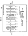
- the second embodiment will be described with an example in which a base station 100a transmits signals by an OFDM method which is a multi-carrier transmission method using a plurality of sub-carriers, and a base station 100b transmits signals by a conventional transmission method such as a CDMA method.
- Fig. 6 shows a transmitting apparatus 100 according to this embodiment
- Fig. 8 shows a receiving apparatus 200 according to this embodiment.
- the difference between the transmitting apparatus 100 and the receiving apparatus 200 according to the first embodiment and those according to the prior art will be described mainly.
- the transmitting apparatus 100 includes a coder 101, an interleaver 102, a symbol mapper 103, a sub-carrier mapping unit 131, a pilot multiplexing unit 132, an inverse fast Fourier transforming unit (IFFT) 105, a parallel-serial converting unit (P/S) 106, an insertion circuit 107, a transmission timing adjusting unit 123, a transmitting unit 108 and a transmission method identifying unit 109.
- IFFT inverse fast Fourier transforming unit
- P/S parallel-serial converting unit
- the sub-carrier mapping unit 131 is configured to select a sub-carrier of a frequency bandwidth other than a frequency bandwidth of a sub-carrier used in the system 2 based on the usage carrier information from the transmission method identifying unit 109, and to map an information symbol of a frequency bandwidth input from the coder 103 into the selected sub-carrier.
- the pilot multiplexing unit 132 is configured to multiplex a pilot symbol into the sub-carrier selected by the sub-carrier mapping unit 131, based on the usage carrier information from the transmission method identifying unit 109. For example, the pilot multiplexing unit 132 multiplexes a pilot symbol only into a sub-carrier to be used in the system 1 among allocated positions of the pilot symbol originally scheduled, i.e., only into a sub-carrier associated with a frequency bandwidth used for transmission of information symbols.
- the insertion circuit 107 is configured to add a guard interval and a symbol length adjustment signal to an OFDM signal output from the parallel-serial converting unit 106, based on the symbol length information from the transmission method identifying unit 109.
- the insertion circuit 107 is a circuit which generates a symbol length adjustment signal for making a difference in symbol length (or symbol rate) between the system 1 (the own system) and the system 2 (the different system) zero, based on symbol length information from the transmission method identifying unit 109, and adds the generated symbol length adjustment signal to an OFDM signal.
- the insertion circuit 107 inserts a symbol length adjustment signal between two information symbols divided by each sub-carrier.
- the insertion circuit 107 adds the symbol length adjustment signals to the information symbols S including guard intervals which have already been inserted.
- the insertion circuit 107 can generate a symbol length adjustment signal by copying a part of sample values output from the inverse fast Fourier transforming unit 105 corresponding to 1 OFDM symbol. Furthermore, a symbol length adjustment signal can be used for symbol synchronization, when a synchronization word is.inserted into the symbol length adjustment signal.
- the insertion circuit 107 can generate a part of a symbol length adjustment signal by copying a part of sample values output from the inverse fast Fourier transforming unit 105, and generate the rest of the symbol length adjustment signal by a simple signal constituted only by "0", for example.
- the insertion circuit 107 When receiving symbol length information showing a guard interval length from the transmission method identifying unit 109, the insertion circuit 107 adds a guard interval having the guard interval length to an OFDM signal.
- the guard interval also serves as a symbol length adjustment signal.
- the transmission method identifying unit 109 is configured to communicate a value calculated by subtracting an OFDM symbol length within an effective symbol interval from a symbol length used in the system 2, to the insertion circuit 107, as the guard interval.
- the transmission method identifying unit 109 outputs a difference in symbol length (or symbol rate) between the own system and the different system which are mixed in the same frequency bandwidth.
- the transmission method identifying unit 109 can store a fixed value of the difference, and output the fixed value as a calculation result without calculating the difference.
- the symbol rate of the PDC method is 21 kHz
- the frequency interval of the PDC method is 25 kHz (interleave allocation). Therefore, in order to configure the OFDM method using the same base station as the PDC method, it is necessary to set a sub-carrier interval 1/T of the OFDM method at 25kHz. In this case, the length of 1 symbol interval (symbol length) of the PDC method becomes 47.6 “s, and the length of 1 symbol interval (symbol length) of the OFDM method becomes 40 "s.
- the insertion circuit 107 sets the sum of a guard interval and a symbol length adjustment signal to be inserted into an OFDM signal at 7.6"s, and makes the lengths of 1 symbol interval in the two systems equal.
- the insertion circuit 107 sets the length of the symbol length adjustment signal to be inserted at 2.6 "s.
- the receiving apparatus 200 includes a receiving unit 201, a removal circuit 202, a serial-parallel converting unit (S/P) 203, a fast Fourier transforming unit (FFT) 204, a channel compensating unit 224, a sub-carrier demapping unit 231, a symbol demapper 206, a deinterleaver 207, a decoder 208 and a transmission method identifying unit 209.
- S/P serial-parallel converting unit
- FFT fast Fourier transforming unit
- the removal circuit 202 is a circuit which removes a symbol length adjustment signal and a guard interval added by the transmitting apparatus 100, based on symbol length information from the transmission method identifying unit 209. More specifically, the removal circuit 202 removes a symbol length adjustment signal and a guard interval from an OFDM signal received at the receiving unit 201, and outputs the result to the serial-parallel converting unit (S/P) 203.
- S/P serial-parallel converting unit
- the system 1 Even with the symbol length and the transmission timing completely matched, if the system 1 performs reception in a conventional manner, a transfer function of a band pass filter (BPF) does not have an ideal rectangle form, the system 1 suffers from interference from an adjacent sub-carrier of the OFDM method.
- the receiving apparatus of the different system can use a reception method such as a fast Fourier transforming process after using a band pass filter which passes n adjacent sub-carriers, to solve this problem.
- the second embodiment for example, even when the system 1 (the own system) transmitting information symbols with the OFDM method and the system 2 (the different system) transmitting information symbols with the transmission method other than the OFDM method share the same frequency bandwidth, it is possible to match the symbol lengths (the symbol rates) to be used between the system 1 and the system 2, by adding, to information bits to be transmitted, a symbol length adjustment signal based on the difference between the symbol lengths (the symbol rates) to be used by the system 1 and the system 2.
- the transmitting apparatus 100 (the base station 100a) transmits information symbols with the OFDM method
- the present invention can also be applied to the case where a system 1 which transmits information symbols with a VSF-OFCDM (Variable Spreading Factor - Orthogonal Frequency and Code Division Multiplexing) method and a system 2 which transmits information symbols with a different transmission method are mixed.
- VSF-OFCDM Very Spreading Factor - Orthogonal Frequency and Code Division Multiplexing
- the VSF-OFCDM method is a transmission method which combines a VSF (Variable Spreading Factor) with an OFCDM (Orthogonal Frequency and Code Division Multiplexing).
- the VSF can secure a certain communication quality in accordance with various environments such as cities, suburbs, the indoors and so on, by spreading an information symbol into the time domain and the frequency domain using a spreading code assigned to each mobile station 200, and performing variable control on the spreading factor.
- the OFCDM reduces multi-path influence by transmitting signals of a frequency bandwidth of 100 MHz with a plurality of sub-carriers in parallel, and making a symbol length per sub-carrier longer than a multi-path delay time.
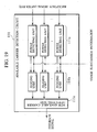
- the transmitting apparatus 100 includes a coder 101, an interleaver 102, a symbol mapper 103, a pilot multiplexing unit 132, a serial-parallel converting unit (S/P) 104, a copying unit 141, a plurality of multiplying units 143, a synthesizing unit 144, an inverse fast Fourier transforming unit (IFFT) 105, a parallel-serial converting unit (P/S) 106, an insertion circuit 107, a transmission timing adjusting unit 123, a transmitting unit 108 and a transmission method identifying unit 109.
- IFFT inverse fast Fourier transforming unit
- P/S parallel-serial converting unit
- the copying unit 141 is a circuit which copies each information symbol of a plurality of information symbol sequences on which the serial-parallel converting process has been performed in the serial-parallel converting unit 104.
- the number of copied information symbols is equal to the chip length of a spreading code.
- the copied information symbols are arranged on the frequency axis, and are output to the multiplying units 143 as a pair of information symbol sequences.
- the spreading code generating unit 142 is a circuit which generates spreading codes having a predetermined spreading factor assigned to each mobile station.
- the number of generated spreading codes is equal to the number of sub-carriers.
- the multiplying unit 143 is a circuit which multiplies each information symbol copied in the copying unit 141 by the spreading code generated by the spreading code generating unit 142.
- the synthesizing unit 144 is a circuit which synthesizes the information symbols multiplied by the plurality of multiplying units 143.
- the receiving apparatus 200 includes a receiving unit 201, a removal circuit 202, a serial-parallel converting unit (S/P) 203, a fast Fourier transforming unit (FFT) 204, a channel estimating unit 241, a spreading code generating unit 242, an adder 244, a parallel-serial converting unit (P/S) 205, a symbol demapper 206, a deinterleaver 207, a decoder 208 and a transmission method identifying unit 209.
- S/P serial-parallel converting unit
- FFT fast Fourier transforming unit
- P/S parallel-serial converting unit
- the channel estimating unit 241 is a circuit which extracts a pilot symbol from an output from the fast Fourier transforming unit 204, and estimates a value showing change of a channel of each sub-carrier based on the pilot symbol.
- the multiplying unit 243 is a circuit which compensates the change of each sub-carrier for the output from the fast Fourier transforming unit 204 based on the value estimated by the channel estimating unit 241, and multiply the compensation result by the spreading code generated the spreading code generating unit 242.
- the adder 244 is a circuit which adds the information symbols output from the plurality of multiplying units 243.
- the VSF-OFCDM method which spreads into the time domain and the frequency domain by a spreading code having a spreading factor assigned to each mobile station is adopted and the information symbols are transmitted, matched to a symbol length (or a symbol rate) used in a system of a different transmission method, it is possible to adapt to communication environments such as cities, suburbs, the indoors and so on, and to share the same frequency bandwidth with a system of a different transmission method.
- the fourth embodiment of the present invention will be described.
- the entire configuration of a communications system according to this embodiment the configuration of a base station according to this embodiment and the configuration of a mobile station according to this embodiment are same as those of the above-described second embodiment.
- the insertion circuit 107 is configured to add a symbol length adjustment signal to an information symbol to be transmitted, so that an effective symbol interval (an interval acquired by removing a guard interval from a symbol interval) of the information symbol is positioned in the middle of a symbol interval of the information symbol.
- An OFDM signal transmitted from a base station 100a and a signal of a different transmission method transmitted from a base station 100b are configured to be orthogonal in 1 OFDM symbol interval of the OFDM signal. Both the signals use the same frequency bandwidth.
- the insertion circuit 107 inserts a guard interval before an information symbol S and inserts a symbol length adjustment signal after the information symbol S, so that an effective symbol interval of the information symbols including the symbol length adjustment signal and the guard interval is positioned in the middle of an OFDM symbol interval of the information symbol S.
- the fourth embodiment even when a frequency bandwidth of a transmitted OFDM signal is limited and each information symbol does not have a rectangular form, and a signal of a different transmission method is mixed in the same frequency bandwidth as the OFDM signal, it is possible to prevent an inter-symbol interference by the symbol length adjustment signal, and to keep proper orthogonality.
- the fifth embodiment is characterized by adding a part of a symbol length adjustment signal or the whole of the symbol length adjustment signal to an OFDM signal as a guard interval.
- the OFDM signal copes with a delay of each path in a multi-path propagation route, using the guard interval.
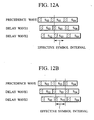
- Fig. 12A it is possible to demodulate an information symbol without the inter-symbol interference, by determining a 1 OFDM symbol interval which becomes effective at the time of demodulation (an effective symbol interval).
- a guard interval and a symbol length adjustment signal are arranged before and after the OFDM symbol S, and a part of the symbol length adjustment signal is used as a guard interval, so as to resolve the above-described inconvenience.
- Fig. 13A shows an example in which the symbol length adjustment signal is arranged after the effective symbol interval of the OFDM symbol, and a part of the symbol length adjustment signal is used as the guard interval.
- the symbol length adjustment signal plays the role of the guard interval, so that the OFDM symbol S is within the effective symbol interval and the system 1 does not suffer from the interference from the front and the back OFDM symbols.
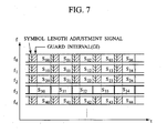
- the sixth embodiment is characterized in that an insertion circuit 107 adds a symbol length adjustment signal to an information symbol to be transmitted, in order to adjust the symbol length of the information symbol so that it becomes a nonnegative integral multiple or a nonnegative integral submultiple of a symbol length used in a different system (system 2).
- the symbol length adjustment signals are added to n (n is an integer equal to or larger than two) information symbols S 00 , S 01 , S 02 , S 03 in the system 1, so that the length of the n information symbols S 00 , S 01 , S 02 , S 03 agrees with the length of one information symbol S 30 in the system 2.
- a method of adding a symbol length adjustment signal to each information symbol shown in Fig. 14A and a method of adding a symbol length adjustment signal to each group of N information signals shown in Fig. 14B .
- a symbol length (or a symbol rate) of the own system is about N times longer (or faster) than a symbol length (or a symbol rate) of the different system (the system 2), as shown in Fig. 14A and Fig. 14B , it is possible to configure a communications system more effectively, by adjusting the adding method of the symbol length adjustment signal.
- the transmission method identifying unit 109 is configured to judge a sub-carrier used in the different system (the system 2) based on control information from the different system and so on in the above-described embodiments
- a transmission method identifying unit 109 in this embodiment is configured to judge a sub-carrier used in a different system based on a reception signal from the different system, when a transmitting apparatus 100 exists independently, in other words, when the control information from the different system and so on cannot be received.
- the transmission method identifying unit 109 of the transmitting apparatus 100 according to the seventh embodiment is configured to judge that a frequency bandwidth associated with a sub-carrier in the different system is used, when a power level of a signal component of the sub-carrier in a reception signal from the different system is larger than a predetermined threshold.
- the transmission method identifying unit 109 includes a receiving unit 109a, a fast Fourier transforming unit (FFT) 109b, a plurality of power detecting units 109c, a plurality of judging units 109d and a usage sub-carrier information generating unit 109e.
- FFT fast Fourier transforming unit
- the receiving unit 109a is configured to receive a signal from the different system (the system 2) via a reception antenna (not shown), and to perform a serial-parallel conversion process on the received signal for outputting to the fast Fourier transforming unit 109b.
- the fast Fourier transforming unit 109b is configured to calculate signal components of each sub-carrier by performing a fast Fourier transforming process on an output from the receiving unit 109a, and to output the calculated signal components to each power detecting unit 109c associated with each sub-carrier. More specifically, the fast Fourier transforming unit 109b performs the fast Fourier transforming process, setting FFT windows, while establishing symbol synchronization.
- the power detecting units 109c are each configured to detect power levels of signal components of each sub-carrier from the fast Fourier transforming unit 109b.
- the judging units 109d are each configured to judge that a frequency bandwidth associated with a sub-carrier in the different system is used, when a power level of a signal component of the sub-carrier exceeds a predetermined threshold. For example, the judging units 109d output "1" to the usage sub-carrier information generating unit 109e as a judging result regarding a used sub-carrier, and output "0" to the usage sub-carrier information generating unit 109e as a judging result regarding an unused sub-carrier.
- the usage sub-carrier information generating unit 109e is configured to gather the judging results in the judging units 109d for outputting as usage sub-carrier information.
- the transmitting apparatus 100 may be configured to receive uplink radio signals and check a usage condition of an uplink radio channel, when the uplink radio channels and downlink radio channels are multiplexed with an FDD method. Also, the transmitting apparatus 100 may be configured to generate usage sub-carrier information in the downlink radio channels in the different system, in accordance with a rule of combining the uplink radio channels and the downlink radio channels in the different system.
- the configuration of the transmission method identifying unit 209 provided in the receiving apparatus 200 may be the configuration of the above-described transmission method identifying unit 109.
- the transmission method identifying unit 209 is configured to feed back the usage sub-carrier information to the transmitting apparatus 100.
- the transmitting apparatus 100 is configured to transmit information symbols using a symbol length and a transmission timing used in a different system, and not to use a sub-carrier used in the different system for transmission of information symbols.
- a transmitting apparatus 100 according to the eighth embodiment is characterized by adjusting so that a frequency bandwidth used in the different system and also a frequency bandwidth adjacent to the frequency bandwidth are not used for transmission of information symbols.
- a sub-carrier mapping unit 131 and a pilot multiplexing unit 132 in a base station 100a belonging to a system 1 of an OFDM method make not only a sub-carrier (a frequency bandwidth f 3 ) used in the system 2 of the PDC method but also sub-carriers of the frequency bandwidths f 2 and f 4 adjacent to the frequency bandwidth f 3 null sub-carriers.
- frequency bandwidths including a interference power level equal to or more than a predetermined threshold may be considered as frequency bandwidths adjacent to the frequency bandwidth of a sub-carrier used in the different system.
- the transmitting apparatus 100 need not synchronize with the different system, so as to transmit information symbols using a symbol length and a transmission timing used in the different system. Furthermore, the transmitting apparatus 100 can reduce an inter-system interference (including influence on the different system) greatly, even when using a symbol length different from a symbol length of the different system.
- a receiving apparatus 200 according to this embodiment is characterized by being able to recognize which frequency bandwidth is used in the own system, even when the frequency bandwidth to be used in the own system and a frequency bandwidth to be used in a different system are dynamically changed.
- a transmission method identifying unit 209 of the receiving apparatus 200 is configured to identify a frequency bandwidth used in one system (system 1) to which the receiving apparatus 200 belongs, based on information regarding a frequency bandwidth associated with a sub-carrier where a power level of a received signal component is equal to or smaller than a predetermined threshold and a frequency bandwidth used in a different system (system 2).
- the transmission method identifying unit 209 identifies the frequency bandwidth used in the system 1, based on null sub-carriers inserted by the transmitting apparatus 100 in the eighth embodiment.
- the transmission method identifying unit 209 has a configuration as shown in Fig. 15 , and can know positions of the null sub-carriers by detecting power levels of the signal components of each sub-carrier.
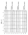
- Fig. 17 on the basis of the fact that frequency bandwidths divided by a null sub-carrier is used in different systems, it is possible to understand that the system 1 uses one of the frequency bandwidths f 0 , f 1 , f 6 , f 7 and the frequency bandwidths f 3 , f 4 , f 9 , f 10 .
- the transmission method identifying unit 209 when the transmission method identifying unit 209 has information regarding a frequency bandwidth used in the system 2, for example, advance information showing that the system 2 does not use the frequency bandwidths f 1 , f 2 , it can judge that the system 1 uses the frequency bandwidths f 0 , f 1 , f 6 , f 7 .
- the transmission method identifying unit 209 can specify a frequency bandwidth used in the system 1, using control information showing "1" if the system 1 occupies frequency bandwidths more than half of the total frequency bandwidths, and "0" if not.
- the transmission method identifying unit 209 may judge a sub-carrier where a power level of a signal component of the sub-carrier is equal to or less than 50% of a power level of a signal component of the sub-carrier predicted from a pilot symbol, to be a null sub-carrier.
- the tenth embodiment is configured to resolve the problem, detects a collision of reception signals in the receiving apparatus, and stops using a sub-carrier in which the collision has been detected immediately, so as to make a plurality of systems coexist in the same frequency bandwidth without interfering with other systems.
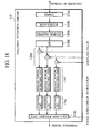
- a receiving apparatus 200 includes a collision detection circuit 110 as shown in Fig. 18 .
- the collision detection circuit 110 includes a symbol mapper 110a, an interleaver 110b, a coder 110c, a serial-parallel converting unit 110d, a plurality of subtractors 110e, a plurality of remain power detecting units 110f, a plurality of judging units 110g and a collision judging unit 110h.
- the symbol mapper 110a, the interleaver 110b, the coder 110c and the serial-parallel converting unit 110d are configured to generate a transmission symbol estimation value in the frequency domain, from decoded bit streams.
- Each subtractor 110e is configured to subtract a sample value of a reception signal after a channel compensation, from each of the above-described transmission symbol estimation values, for output to each remain power detecting unit 110f corresponding to each sub-carrier.
- Each remain power detecting unit 110f is configured to detect a power level of each sub-carrier.
- the judging units 110g are each configured to detect a frequency bandwidth associated with a sub-carrier where a power level detected by the remain power detecting unit 110f is equal to or more than a predetermined threshold (sub-carrier with remaining power), and judge that the frequency bandwidth is used in a different system.
- the judging units 110g each judge a sub-carrier where a power level equal to or more than a predetermined threshold is detected to be a usage sub-carrier in a different system for output to the collision judging unit 110h.
- the collision judging unit 110h Based on usage sub-carrier information from the transmission method identifying unit 209 and judgment results from the judging units 110g, the collision judging unit 110h compares a frequency bandwidth currently used in the own system with a frequency bandwidth used in a different system. When the same frequency bandwidth is used in both the systems, it judges that a signal collision has occurred. The collision judging unit 110h communicates the occurrence of the signal collision as a feedback signal to the transmitting apparatus 100.
- the collision circuit 110 may be configured to further include an error detecting unit to perform the above-described process after confirming that no error exists in a bit stream.
- the remain power detecting units 110f may be configured to output average remaining power of a plurality of OFDM symbols (e.g., of one frame).
- a receiving apparatus 200 in this embodiment is provided with an available carrier detection circuit 111 in place of the collision detection circuit 110 in the receiving apparatus 200 in the above-described tenth embodiment.
- the available carrier detection circuit 111 includes a plurality of power detecting units 111a, a plurality of judging units 111b, and a new available carrier detecting unit 111.
- the power detecting units 111a are configured to detect a power level of each reception signal component after fast Fourier transform (or after channel compensation).
- the power detecting units 111a are configured such that only those corresponding to currently unused sub-carriers operate, based on usage sub-carrier information.
- the judging units 111b are configured to detect a frequency bandwidth associated with a sub-carrier where a power level of a reception signal component is equal to or lower than (or below) a predetermined threshold.
- the judging units 111b are configured such that only those corresponding to currently unused sub-carriers operate, based on usage sub-carrier information.
- the judging units 111b may be configured such that those corresponding to sub-carriers of frequency bandwidths used in a different system do not operate.
- the judging units 111b are each configured to output "0" when an associated sub-carrier is currently used or an associated sub-carrier is not used and the power level is equal to or greater than the threshold, and to output "1" when an associated sub-carrier is not currently used and the power level is below the threshold.
- the new available carrier detecting unit 111c is configured to detect a frequency bandwidth unused in a system (system 1) to which the receiving apparatus 200 belongs and in a different system (system 2), based on a frequency bandwidth used in the different system identified by a transmission method identifying unit 209 and a frequency bandwidth detected by the judging units 111b.
- the new available carrier detecting unit 111c detects a sub-carrier of a frequency bandwidth unused in both the system 1 and the system 2, based on judgment results from the determining units 111b. Then, the new available carrier detecting unit 111c refers to usage sub-carrier information from the transmission method identifying unit 209, and detects a new sub-carrier of a frequency bandwidth which stops being used in both the systems to communicate it as a feedback signal to the transmitting apparatus 100.
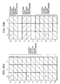
- a pilot multiplexing unit 132 in a transmitting apparatus 100 of this embodiment is configured to multiplex a scattered pilot symbol.
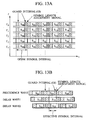
- Fig. 20A illustrates the arrangement of pilot symbols when a system 1 of an OFDM method exclusively uses all the frequency bandwidths f 0 to f 10 .
- pilot symbols P 1 , P 2 and P 3 are multiplexed in a time slot to of the frequency bandwidth f 0 , a time slot to of the frequency bandwidth f 4 , and a time slot to of the frequency bandwidth f 8 , respectively. Since scattered pilot symbols are herein used, a channel estimate in a time slot in which a pilot symbol is not multiplexed can be obtained by complementing a channel estimate in a time slot in which a pilot symbol is multiplexed.
- Fig. 20B illustrates the arrangement of pilot symbols when a system 2 of a PDC method uses the frequency bandwidths f 3 and f 4 .
- pilot symbols P 1 and P 3 are multiplexed in a time slot to of the frequency bandwidth f 0 and a time slot to in the frequency bandwidth f8, respectively. Since the frequency bandwidth f 4 is used by the system 2, the pilot symbol P 2 is not multiplexed.
- the transmitting apparatus 100 in this embodiment is configured to solve this problem.
- the pilot multiplexing unit 132 is configured to multiplex pilot symbols in sub-carries associated with the frequency bandwidths f 1 and f 6 adjacent to the frequency bandwidths f 2 and f 5 which are not used for transmission of information symbols.
- the transmitting apparatus 100 is configured to use a predetermined algorithm which is also used by the receiving apparatus 200 according to a sub-carrier associated with a frequency bandwidth for use in transmission of information symbols, to determine the arrangement of pilot symbols to be multiplexed.
- the transmitting apparatus 100 may alternatively be configured to communicate the arrangement of pilot symbols to the receiving apparatus 200 by control information or the like.
- this embodiment can be implemented without communicating the above-described control information.
- the transmitting apparatus 100 and the receiving apparatus 200 can share a rule that, in time slots t0 in which pilot symbols are arranged, pilot symbols be arranged in the frequency bandwidths f 1 and f 6 adjacent to the frequency bandwidths f 2 and f 5 which are judged to be non-usage frequency bandwidths due to the influence of occupation by the system 2, thereby to implement this embodiment.
- This embodiment enables dynamic sharing of frequency bandwidths by a plurality of systems without reducing channel estimate precision.
- a transmitting apparatus and a receiving apparatus can share a pilot symbol arrangement algorithm according to a sub-carrier used in the own system to rearrange pilot symbols in the transmitting apparatus and the receiving apparatus without using a control signal.
- This embodiment is for a case where a system 1 starts communication using a frequency bandwidth unused in a system 2 while the system 2 performs communication.
- a receiving apparatus 200 in this embodiment can judge which frequency bandwidth is used in the own system even when frequency bandwidths occupied by the own system and a different system change dynamically and no null sub-carriers are inserted by a transmitting apparatus 100.
- the receiving apparatus 200 in this embodiment includes a frame synchronizing unit 251 and a plurality of 1 OFDM symbol delaying unit 252 in addition to the components in the receiving apparatus 200 shown in Fig. 8 .
- a transmission method identifying unit 209 includes a plurality of 2 OFDM symbol delaying units 209a, a plurality of power detecting units 209b, a plurality of judging units 209c, and a usage carrier judging unit 209d.
- the frame synchronizing unit 251 uses a correlation between an output from a channel compensating unit 224 and a pilot symbol to detect the head of a frame used in an OFDM method.
- the frame synchronizing unit 251 uses a pilot symbol arranged in an OFDM symbol in the head of a frame to establish frame synchronization.
- the OFDM symbol in the head of the frame includes a data symbol together with the pilot symbol.
- a sub-carrier demapping unit 231 needs to start a reception process on data symbols from an OFDM symbol at the time of establishment of frame synchronization.
- the 1 OFDM symbol delaying units 252 corresponding to respective sub-carriers are provided between the sub-carrier demapping unit 231 and the channel compensating unit 224.
- the transmission method identifying unit 209 is configured to identify a frequency bandwidth used in a system (system 1) to which the receiving apparatus 200 belongs, based on reception power of each sub-carrier in an interval before the head of an OFDM frame used in the system 1.
- reception power of sub-carriers of frequency bandwidths used in a system 2 is only detected.
- each power detecting unit 209b detects reception power of the corresponding sub-carrier from an output from the 2 OFDM symbol delaying unit 209a, that is, from an OFDM symbol in a time slot before the head of an OFDM frame used in the system 1.
- the judging units 209c detect reception power of sub-carriers of frequency bandwidths used in the system 2, based on outputs from the power detecting units 209b. At that time, in consideration of the influence of noise power and the like, the judging units 209c can judge a sub-carrier having a power level equal to or more than a predetermined threshold to be a sub-carrier of a frequency bandwidth used in a different system (system 2).
- the usage carrier judging unit 209d judges a sub-carrier other than sub-carriers of frequency bandwidths used in the different system (system 2) to be a sub-carrier used in the own system, and communicates the judgment result as usage sub-carrier information to a sub-carrier demapper 231.
- a communication system according to modification 1 is configured such that the transmission method identifying unit 109 provided in the base station 100 in the above-described embodiments is provided in a control device 400.
- the control device 400 is configured to communicate information on a transmission method such as usage sub-carrier information, symbol length information, and transmission timing information to a base station 100a.
- the base station 100a transmits information symbols based on information on the transmission method communicated from the control device 400.
- the base station 100a is configured to add symbol length adjustment signals to signals to be transmitted by different transmission methods via the same transmission antenna for transmission.
- control programs can be installed in computers provided at the base station 100a, the control device 400, a relay device (not shown) and the like to easily build the communication systems in the above-described embodiments and their modifications.
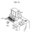
- control programs can be recorded on record media 1001 to 1004 readable by a general-purpose computer 1005 as shown in Fig. 25 .
- control programs can be recorded on various record media including magnetic recording media such as a flexible disk 1001 and a cassette tape 1004, optical disks such as a CD-ROM and a DVD-ROM 1002, and a RAM card 1003.
- magnetic recording media such as a flexible disk 1001 and a cassette tape 1004
- optical disks such as a CD-ROM and a DVD-ROM 1002
- Such computer-readable record media recorded on which the control programs are recorded allow the communications systems and communications methods according to the above-described embodiments and modifications to be implemented using a general-purpose computer and a dedicated-purpose computer, and also facilitate the storage, transport and installation of the control programs.
- the present invention allows a system of a wideband OFDM method and a system of a narrowband transmission scheme to be mixed in the same frequency bandwidth, and thus allows use of two transmission methods in the same frequency bandwidth.
- a new-generation and a current-generation communications methods can be mixed, and thus a communications method can be changed from a current method to a new method in stages smoothly.
Claims (17)
- Système de communication dans lequel une pluralité de systèmes partagent une largeur de bande de fréquences pour transmettre des symboles d'information ; dans lequel
un de la pluralité de systèmes (1) comprend :une unité d'identification (109) configurée pour identifier une première longueur de symbole d'un symbole d'information transmis dans un système différent (2) ; etune unité d'ajustement (122) configurée pour ajuster une seconde longueur de symbole d'un symbole d'information devant être transmis dans l'un de la pluralité de systèmes (1), selon la première longueur de symbole identifiée. - Procédé de communication dans lequel une pluralité de systèmes partagent une largeur de bande de fréquences pour transmettre des symboles d'information, comprenant les étapes de :identification, dans un de la pluralité de systèmes (1), d'une première longueur de symbole d'un symbole d'information transmis dans un système différent (2) ; etajustement, dans l'un de la pluralité de systèmes (1), d'une seconde longueur de symbole d'un symbole d'information devant être transmis, selon la première longueur de symbole identifiée.
- Appareil de transmission devant être mis en oeuvre dans un système de communication dans lequel une pluralité de systèmes partagent une largeur de bande de fréquences pour transmettre des symboles d'information, comprenant :une unité d'identification (109) configurée pour identifier une première longueur de symbole d'un symbole d'information transmis dans un système différent ; etune unité d'ajustement (122) configurée pour ajuster une seconde longueur de symbole d'un symbole d'information devant être transmis dans l'un de la pluralité de systèmes (1), selon la première longueur de symbole identifiée.
- Appareil de transmission selon la revendication 3, dans lequel
l'unité d'identification (109) est configurée pour identifier une synchronisation de transmission du symbole d'information dans le système différent (2) ; et
l'unité d'ajustement (122) est configurée pour ajuster une synchronisation de transmission du symbole d'information devant être transmis dans l'un de la pluralité de systèmes (1), selon une synchronisation de transmission identifiée. - Appareil de transmission selon la revendication 3, dans lequel
l'appareil de transmission est configuré pour transmettre les symboles d'information en utilisant un procédé de multiplexage par division de fréquence orthogonale OFDM ;
l'appareil de transmission comprend une unité d'étalement configurée pour étaler le symbole d'information devant être transmis, avec un code d'étalement attribué à un appareil de réception ; et
l'unité d'ajustement (122) est configurée pour ajuster la longueur de symbole d'un symbole d'information étalé, selon la longueur de symbole identifiée. - Appareil de transmission selon la revendication 3, dans lequel
l'unité d'ajustement (122) est configurée pour ajuster la longueur de symbole du symbole d'information devant être transmis, en ajoutant un signal d'ajustement de longueur de symbole au symbole d'information de sorte qu'un intervalle de symbole efficace du symbole d'information est fixé au milieu d'un intervalle de symbole du symbole d'information. - Appareil de transmission selon la revendication 6, dans lequel
l'appareil de transmission est configuré pour transmettre les symboles d'information en utilisant un procédé de multiplexage par division de fréquence orthogonale OFDM ; et
une partie du signal d'ajustement de longueur de symbole ou la totalité du signal d'ajustement de longueur de symbole constitue un intervalle de garde. - Appareil de transmission selon la revendication 3, dans lequel
l'unité d'ajustement (122) est configurée pour ajuster la longueur de symbole du symbole d'information devant être transmis de sorte que la longueur de symbole du symbole d'information devient un multiple entier non négatif ou un sous-multiple entier non négatif d'une longueur de symbole détectée. - Appareil de transmission selon la revendication 3, dans lequel
l'appareil de transmission est configuré pour transmettre les symboles d'information en utilisant un procédé de multiplexage par division de fréquence orthogonale OFDM ;
l'unité d'identification (109) est configurée pour identifier une largeur de bande de fréquences utilisée dans le système différent ; et
l'unité d'ajustement (122) est configurée pour ajuster afin de ne pas utiliser une largeur de bande de fréquences identifiée et une largeur de bande de fréquences adjacente à la largeur de bande de fréquences identifiée pour la transmission du symbole d'information. - Appareil de transmission selon la revendication 9, comprenant :une unité de multiplexage pilote (132) configurée pour multiplexer un symbole pilote dans la sous-porteuse sélectionnée par une unité de mise en correspondant de sous-porteuse (131), sur base des informations de porteuse d'utilisation en provenance de l'unité d'identification (109).
- Appareil de transmission selon la revendication 10, dans lequel
l'unité de multiplexage pilote (132) est configurée pour multiplexer le symbole pilote sur une sous-porteuse qui est associée à une largeur de bande de fréquences adjacente à une largeur de bande de fréquences ne devant pas être utilisée pour la transmission du symbole d'information. - Appareil de transmission selon la revendication 3, dans lequel
l'appareil de transmission est configuré pour transmettre les symboles d'information en utilisant un procédé OFDM ; et
l'unité d'identification (109) est configurée pour juger qu'une largeur de bande de fréquences associée à une sous-porteuse dans un signal de réception en provenance du système différent (2) est utilisée dans le système différent (2), quand un niveau de puissance d'une composante de signal de la sous-porteuse est plus grand qu'un seuil prédéterminé. - Appareil de réception devant être mis en oeuvre dans un système de communication selon la revendication 1, dans lequel une pluralité de systèmes (1, 2) partagent une largeur de bande de fréquences pour transmettre des symboles d'information, comprenant :une unité de réception (201) configurée pour recevoir des signaux d'information transmis dans un de la pluralité de systèmes ;une unité d'identification (209) configurée pour identifier une longueur de symbole d'un symbole d'information transmis dans un système différent (2) ;une unité d'ajustement (222) configurée pour enlever un signal d'ajustement de longueur de symbole d'un symbole d'information reçu, selon la longueur de symbole identifiée ;un dispositif d'annulation d'interférence (223) configuré pour générer une réplique du signal d'information reçu du système différent (2), et pour soustraire la réplique du signal d'information reçu par l'unité de réception (201), les symboles d'information étant transmis en utilisant un procédé OFDM ; etl'unité d'identification (209) est configurée pour identifier une largeur de bande de fréquences utilisée dans un de la pluralité de systèmes auquel l'appareil de réception appartient, sur base d'informations concernant une largeur de bande de fréquences associée à une sous-porteuse dans laquelle un niveau de puissance d'une composante de signal reçu est inférieur ou égal à un seuil prédéterminé et sur des informations concernant une largeur de bande de fréquences utilisée dans le système différent (2).
- Appareil de réception selon la revendication 13, dans lequel
l'appareil de réception est configuré pour recevoir les symboles d'information transmis en utilisant un procédé de multiplexage par division de fréquence orthogonale OFDM ; et
l'appareil de réception comprend :une unité de détection de puissance (209b) configurée pour détecter une largeur de bande de fréquences associée à une sous-porteuse dans laquelle un niveau de puissance d'une composante de signal reçu est supérieur ou égal à un seuil prédéterminé ; etune unité de détection de collision (209c) configurée pour détecter une collision de signaux dans la même largeur de bande de fréquences, sur base d'une largeur de bande de fréquences utilisée dans le système différent (2) qui est identifiée par l'unité d'identification (209) et sur la largeur de bande de fréquences détectée par l'unité de détection de puissance (209b). - Appareil de réception selon la revendication 13, dans lequel
l'appareil de réception est configuré pour recevoir les symboles d'information transmis en utilisant un procédé de multiplexage par division de fréquence orthogonale OFDM ; et
l'appareil de réception comprend :une unité de détection de puissance (209b) configurée pour détecter une largeur de bande de fréquences associée à une sous-porteuse dans laquelle un niveau de puissance d'une composante de signal reçu est inférieur ou égal à un seuil prédéterminé ; etune unité de détection de largeur de bande de fréquences de non-utilisation (209d) configurée pour détecter une largeur de bande de fréquences qui n'est pas utilisée dans un de la pluralité de systèmes auquel l'appareil de réception appartient et dans le système différent (2), sur base d'une largeur de bande de fréquences utilisée dans le système différent qui est identifiée par l'unité d'identification (209) et la largeur de bande de fréquence détectée par l'unité de détection de puissance (209b). - Appareil de réception selon la revendication 13, dans lequel
l'appareil de réception est configuré pour recevoir les symboles d'information transmis en utilisant un procédé de multiplexage par division de fréquence orthogonale OFDM ; et
l'unité d'identification (209) est configurée pour identifier une largeur de bande de fréquences utilisée sur un de la pluralité de systèmes auquel l'appareil de réception appartient, sur base d'une puissance de réception d'une sous-porteuse dans un intervalle précédant une tête d'une trame OFDM. - Programme de commande qui commande un appareil de transmission appartenant à un d'une pluralité de systèmes (1, 2), l'appareil de transmission étant mis en oeuvre dans un système de communication dans lequel la pluralité de systèmes (1, 2) partage une largeur de bande de fréquences pour transmettre des symboles d'information ; dans lequel
le programme de commande peut être directement chargé dans une mémoire interne de l'appareil de transmission et comprend des parties de code logiciel pour effectuer les étapes :d'identification d'une première longueur de symbole d'un symbole d'information transmis dans un système différent (2) ; etde notification à l'appareil de transmission d'un signal d'ajustement de longueur de symbole devant être ajouté à un symbole d'information à transmettre, de façon à ajuster une seconde longueur de symbole du symbole d'information, selon la longueur de symbole identifiée.
Applications Claiming Priority (3)
| Application Number | Priority Date | Filing Date | Title |
|---|---|---|---|
| JP2002337139 | 2002-11-20 | ||
| JP2002337139 | 2002-11-20 | ||
| PCT/JP2003/014824 WO2004047348A1 (fr) | 2002-11-20 | 2003-11-20 | Systeme et procede de communication, dispositif d'emission, dispositif de reception et programme de commande |
Publications (3)
| Publication Number | Publication Date |
|---|---|
| EP1566907A1 EP1566907A1 (fr) | 2005-08-24 |
| EP1566907A4 EP1566907A4 (fr) | 2008-10-22 |
| EP1566907B1 true EP1566907B1 (fr) | 2010-06-23 |
Family
ID=32321832
Family Applications (1)
| Application Number | Title | Priority Date | Filing Date |
|---|---|---|---|
| EP20030774092 Expired - Fee Related EP1566907B1 (fr) | 2002-11-20 | 2003-11-20 | Système et procédé de communication, dispositif d'emission, dispositif de réception et programme de commande |
Country Status (6)
| Country | Link |
|---|---|
| US (1) | US7633924B2 (fr) |
| EP (1) | EP1566907B1 (fr) |
| JP (1) | JP4009641B2 (fr) |
| CN (1) | CN1714525B (fr) |
| DE (1) | DE60333117D1 (fr) |
| WO (1) | WO2004047348A1 (fr) |
Families Citing this family (35)
| Publication number | Priority date | Publication date | Assignee | Title |
|---|---|---|---|---|
| EP3364573B1 (fr) * | 2004-10-29 | 2024-03-20 | Sharp Kabushiki Kaisha | Procédé de communication et transmetteur radio |
| US8150442B2 (en) | 2005-01-18 | 2012-04-03 | Sharp Kabushiki Kaisha | Method and apparatus for controlling power of subcarriers in a wireless communication system |
| JP4526977B2 (ja) * | 2005-03-02 | 2010-08-18 | 株式会社エヌ・ティ・ティ・ドコモ | 送信機および送信制御方法 |
| EP1952660A1 (fr) * | 2005-11-07 | 2008-08-06 | Thomson Licensing | Appareil et procede de selection de frequence dynamique dans des reseaux ofdm |
| CN101371503B (zh) * | 2006-01-11 | 2013-09-25 | 高通股份有限公司 | 用于在广域网与局域对等网络之间共享带宽的方法和装置 |
| US8811369B2 (en) | 2006-01-11 | 2014-08-19 | Qualcomm Incorporated | Methods and apparatus for supporting multiple communications modes of operation |
| JP4531722B2 (ja) * | 2006-05-01 | 2010-08-25 | 株式会社エヌ・ティ・ティ・ドコモ | ユーザ装置、送信方法及び移動通信システム |
| JP4861796B2 (ja) * | 2006-11-15 | 2012-01-25 | ルネサスエレクトロニクス株式会社 | 無線通信装置及び通信処理回路 |
| JP4930006B2 (ja) * | 2006-11-22 | 2012-05-09 | 日本電気株式会社 | 移動通信装置、移動通信システム及びそれに用いる消費電力削減方法 |
| JP2008177693A (ja) * | 2007-01-16 | 2008-07-31 | Futaba Corp | Ofdm方式通信システム及びofdm方式受信装置 |
| KR101236624B1 (ko) * | 2007-02-01 | 2013-02-22 | 삼성전자주식회사 | 이종망간 서비스 연동 방법과 장치 및 시스템 |
| JPWO2008139624A1 (ja) * | 2007-05-15 | 2010-07-29 | パナソニック株式会社 | Ofdm送信装置及びofdm受信装置 |
| JP4924201B2 (ja) | 2007-05-23 | 2012-04-25 | 日本電気株式会社 | 受信品質測定装置および受信品質測定方法 |
| ES2379625T3 (es) * | 2007-09-28 | 2012-04-30 | Lg Electronics Inc. | Aparato y método para transmitir y recibir una señal |
| KR100904533B1 (ko) * | 2008-01-11 | 2009-06-25 | 엘지전자 주식회사 | 전송 타이밍 조절 방법, 연속적인 패킷 전송 방법 및 이동통신 단말 |
| JP5031600B2 (ja) * | 2008-01-28 | 2012-09-19 | 京セラ株式会社 | 無線通信方法、無線通信システム、基地局、移動局 |
| JP5031633B2 (ja) * | 2008-01-28 | 2012-09-19 | 京セラ株式会社 | 無線通信方法、無線通信システム、基地局 |
| JP5031632B2 (ja) * | 2008-03-26 | 2012-09-19 | 京セラ株式会社 | 無線通信方法、無線通信システム、基地局、移動局 |
| US8199739B2 (en) * | 2008-03-29 | 2012-06-12 | Qualcomm Incorporated | Return link time adjustments in FDD OFDMA or SC-FDM systems |
| EP3514993A1 (fr) * | 2008-03-31 | 2019-07-24 | Panasonic Intellectual Property Management Co., Ltd. | Récepteur, procédé de réception, programme de réception, circuit intégré et télévision numérique |
| US8595501B2 (en) | 2008-05-09 | 2013-11-26 | Qualcomm Incorporated | Network helper for authentication between a token and verifiers |
| JP4962412B2 (ja) * | 2008-05-27 | 2012-06-27 | 株式会社デンソー | キャリアセンス回路 |
| JP5247354B2 (ja) * | 2008-10-29 | 2013-07-24 | 京セラ株式会社 | 基地局装置 |
| JP4865048B2 (ja) * | 2010-03-15 | 2012-02-01 | 株式会社東芝 | 情報処理装置、その接続確立方法、および無線通信機器 |
| CN102487371B (zh) * | 2010-12-02 | 2014-03-19 | 无锡物联网产业研究院 | 一种带宽调整方法、发射机和接收机 |
| JP5095834B2 (ja) * | 2011-03-14 | 2012-12-12 | 日本電信電話株式会社 | 光ofcdm伝送システム |
| CN103458415B (zh) * | 2012-05-28 | 2016-12-28 | 华为技术有限公司 | 虚子载波动态设置方法、接收方法和装置及系统 |
| EP4040843A1 (fr) * | 2014-10-31 | 2022-08-10 | Mitsubishi Electric Corporation | Système de radiocommunication, station de base et terminal de communication |
| US10098083B2 (en) * | 2015-04-03 | 2018-10-09 | Qualcomm Incorporated | Clock drift management for coexistence and concurrency |
| JP6299822B2 (ja) * | 2016-08-29 | 2018-03-28 | Nttエレクトロニクス株式会社 | 既知信号検出方法 |
| US10334533B2 (en) | 2016-11-02 | 2019-06-25 | At&T Intellectual Property I, L.P. | Non-orthogonal design for channel state information reference signals for a 5G air interface or other next generation network interfaces |
| US10237032B2 (en) | 2017-01-06 | 2019-03-19 | At&T Intellectual Property I, L.P. | Adaptive channel state information reference signal configurations for a 5G wireless communication network or other next generation network |
| US10320512B2 (en) | 2017-01-08 | 2019-06-11 | At&T Intellectual Property I, L.P. | Interference cancelation for 5G or other next generation network |
| KR102604088B1 (ko) * | 2017-07-06 | 2023-11-22 | 소니그룹주식회사 | 통신 디바이스 및 통신 방법 |
| JP6730249B2 (ja) * | 2017-12-01 | 2020-07-29 | ソフトバンク株式会社 | 無線装置及び無線システム |
Family Cites Families (30)
| Publication number | Priority date | Publication date | Assignee | Title |
|---|---|---|---|---|
| US2003A (en) * | 1841-03-12 | Improvement in horizontal windivhlls | ||
| US6334219B1 (en) * | 1994-09-26 | 2001-12-25 | Adc Telecommunications Inc. | Channel selection for a hybrid fiber coax network |
| DE69711957T2 (de) * | 1996-02-02 | 2002-09-19 | Thomson Brandt Gmbh | Verfahren und Einrichtung zum Empfang von Mehrträgersignalen |
| US6175550B1 (en) * | 1997-04-01 | 2001-01-16 | Lucent Technologies, Inc. | Orthogonal frequency division multiplexing system with dynamically scalable operating parameters and method thereof |
| EP2254301B1 (fr) * | 1998-01-06 | 2013-06-19 | Mosaid Technologies Incorporated | Système de modulation multiporteuse à débits de symboles variables |
| FR2774536B1 (fr) * | 1998-02-02 | 2000-03-10 | Alsthom Cge Alcatel | Procede de detection d'un ou plusieurs canaux libres dans un multiplex temporel optique, un dispositif de mise en oeuvre et une application du dispositif |
| US7787514B2 (en) * | 1998-02-12 | 2010-08-31 | Lot 41 Acquisition Foundation, Llc | Carrier interferometry coding with applications to cellular and local area networks |
| US7430257B1 (en) * | 1998-02-12 | 2008-09-30 | Lot 41 Acquisition Foundation, Llc | Multicarrier sub-layer for direct sequence channel and multiple-access coding |
| EP0938208A1 (fr) * | 1998-02-22 | 1999-08-25 | Sony International (Europe) GmbH | Transmission multiporteuse, compatible au système GSM existant |
| US6061331A (en) * | 1998-07-28 | 2000-05-09 | Gte Laboratories Incorporated | Method and apparatus for estimating source-destination traffic in a packet-switched communications network |
| JP2000244441A (ja) * | 1998-12-22 | 2000-09-08 | Matsushita Electric Ind Co Ltd | Ofdm送受信装置 |
| JP2001069110A (ja) * | 1999-08-25 | 2001-03-16 | Matsushita Electric Ind Co Ltd | Ofdm通信装置 |
| JP3544635B2 (ja) * | 1999-10-05 | 2004-07-21 | 松下電器産業株式会社 | 送受信装置および送受信方法 |
| US6580705B1 (en) * | 1999-10-28 | 2003-06-17 | Lucent Technologies Inc. | Signal combining scheme for wireless transmission systems having multiple modulation schemes |
| SG108240A1 (en) * | 2000-02-23 | 2005-01-28 | Ntt Docomo Inc | Multi-carrier cdma radio transmitting method and apparatus, and channel estimation method and apparatus for multi-carrier cdma radio transmitting system |
| US7170850B2 (en) * | 2000-03-06 | 2007-01-30 | Sony Corporation | Transmission apparatus and method and providing medium thereof |
| JP4337228B2 (ja) * | 2000-04-13 | 2009-09-30 | ソニー株式会社 | Ofdm受信装置及び方法 |
| US6816848B1 (en) | 2000-06-12 | 2004-11-09 | Ncr Corporation | SQL-based analytic algorithm for cluster analysis |
| US7295509B2 (en) * | 2000-09-13 | 2007-11-13 | Qualcomm, Incorporated | Signaling method in an OFDM multiple access system |
| JP2002141888A (ja) * | 2000-11-02 | 2002-05-17 | Matsushita Electric Ind Co Ltd | 非対称無線通信方法 |
| JP3553038B2 (ja) * | 2000-11-06 | 2004-08-11 | 株式会社エヌ・ティ・ティ・ドコモ | 信号送信方法、信号受信方法、送信装置、受信装置および記録媒体 |
| EP1207664A3 (fr) * | 2000-11-16 | 2005-08-03 | Pioneer Corporation | Contrôle de gain dans un récepteur de signaux MDFO |
| JP4341176B2 (ja) * | 2000-12-08 | 2009-10-07 | ソニー株式会社 | 受信同期装置およびそれを用いた復調装置 |
| US6829471B2 (en) * | 2001-03-07 | 2004-12-07 | Andrew Corporation | Digital baseband receiver in a multi-carrier power amplifier |
| US7539664B2 (en) * | 2001-03-26 | 2009-05-26 | International Business Machines Corporation | Method and system for operating a rating server based on usage and download patterns within a peer-to-peer network |
| JP4644978B2 (ja) * | 2001-06-15 | 2011-03-09 | パナソニック株式会社 | Ofdm通信システム、ofdm通信方法およびofdm通信装置 |
| US7548506B2 (en) * | 2001-10-17 | 2009-06-16 | Nortel Networks Limited | System access and synchronization methods for MIMO OFDM communications systems and physical layer packet and preamble design |
| JP3649326B2 (ja) * | 2001-11-13 | 2005-05-18 | 日本電気株式会社 | Ofdm方式のガードインターバル長制御方法及びofdm送受信装置 |
| US20050003828A1 (en) * | 2002-04-09 | 2005-01-06 | Sugar Gary L. | System and method for locating wireless devices in an unsynchronized wireless environment |
| US20040081131A1 (en) * | 2002-10-25 | 2004-04-29 | Walton Jay Rod | OFDM communication system with multiple OFDM symbol sizes |
-
2003
- 2003-11-20 WO PCT/JP2003/014824 patent/WO2004047348A1/fr active Application Filing
- 2003-11-20 EP EP20030774092 patent/EP1566907B1/fr not_active Expired - Fee Related
- 2003-11-20 CN CN2003801036693A patent/CN1714525B/zh not_active Expired - Fee Related
- 2003-11-20 DE DE60333117T patent/DE60333117D1/de not_active Expired - Lifetime
- 2003-11-20 JP JP2004553220A patent/JP4009641B2/ja not_active Expired - Fee Related
- 2003-11-20 US US10/535,859 patent/US7633924B2/en not_active Expired - Fee Related
Also Published As
| Publication number | Publication date |
|---|---|
| JPWO2004047348A1 (ja) | 2006-03-23 |
| DE60333117D1 (de) | 2010-08-05 |
| WO2004047348A1 (fr) | 2004-06-03 |
| CN1714525B (zh) | 2011-04-20 |
| EP1566907A1 (fr) | 2005-08-24 |
| US20060031583A1 (en) | 2006-02-09 |
| CN1714525A (zh) | 2005-12-28 |
| EP1566907A4 (fr) | 2008-10-22 |
| JP4009641B2 (ja) | 2007-11-21 |
| US7633924B2 (en) | 2009-12-15 |
Similar Documents
| Publication | Publication Date | Title |
|---|---|---|
| EP1566907B1 (fr) | Système et procédé de communication, dispositif d'emission, dispositif de réception et programme de commande | |
| KR100572577B1 (ko) | 직교 주파수 분할 다중 통신 시스템 및 방법 | |
| EP1158709B1 (fr) | Format de signal dans un systeme de transmission amrc a porteuses multiples | |
| KR100880991B1 (ko) | 이동통신 시스템에서 다중 안테나를 이용한 파일럿 송수신장치 및 방법 | |
| US9559758B2 (en) | Transmission/reception apparatus and method for supporting MIMO technology in a forward link of a high rate packet data system | |
| US20070177501A1 (en) | Signaling Requirements to Support Interference Coordination in OFDMA Based Systems | |
| JP3987858B2 (ja) | 無線通信システム、無線送信装置、無線受信装置及び無線通信方法 | |
| US20110249764A1 (en) | Radio parameter group generating apparatus, transmitter and receiver | |
| WO2008013080A1 (fr) | Système de communication radio, station de base, appareil terminal et procédé de commande de signaux pilotes | |
| JP4564501B2 (ja) | 周波数分割通信システム | |
| KR20100080568A (ko) | 기지국 및 그 mimo-ofdm 통신 방법 | |
| KR20060007052A (ko) | 무선 주파수 도약 통신 시스템에서 간섭 제거를 이용하는소프트 핸드오프 | |
| JP2010220240A (ja) | 無線局 | |
| WO2007074371A2 (fr) | Dispositif, procede et programme informatique permettant d'assurer les transmissions multidiffusion et unidiffusion en multiplexage de domaine de frequence | |
| JP2010154417A (ja) | 無線通信システム、無線通信方法、及び無線送受信装置 | |
| EP1777869B1 (fr) | Procédé et appareil de planification des canaux dans un système OFDM | |
| US20070127361A1 (en) | Ofdm transmission apparatus, ofdm reception apparatus, and method | |
| KR20070058271A (ko) | 직교 주파수 분할 다중 접속 시스템의 수신기에서 인접 셀간섭 신호를 제거하는 방법 및 장치 | |
| JP2001086086A (ja) | 無線送受信装置及び無線通信方法 | |
| JP2011193488A (ja) | 基地局、移動局及び通信方法 |
Legal Events
| Date | Code | Title | Description |
|---|---|---|---|
| PUAI | Public reference made under article 153(3) epc to a published international application that has entered the european phase |
Free format text: ORIGINAL CODE: 0009012 |
|
| 17P | Request for examination filed |
Effective date: 20050607 |
|
| AK | Designated contracting states |
Kind code of ref document: A1 Designated state(s): DE GB |
|
| A4 | Supplementary search report drawn up and despatched |
Effective date: 20080919 |
|
| 17Q | First examination report despatched |
Effective date: 20090204 |
|
| GRAP | Despatch of communication of intention to grant a patent |
Free format text: ORIGINAL CODE: EPIDOSNIGR1 |
|
| RTI1 | Title (correction) |
Free format text: COMMUNICATION SYSTEM, COMMUNICATION METHOD, TRANSMISSION DEVICE, RECEPTION DEVICE, AND CONTROL PROGRAM |
|
| GRAS | Grant fee paid |
Free format text: ORIGINAL CODE: EPIDOSNIGR3 |
|
| GRAA | (expected) grant |
Free format text: ORIGINAL CODE: 0009210 |
|
| AK | Designated contracting states |
Kind code of ref document: B1 Designated state(s): DE GB |
|
| REF | Corresponds to: |
Ref document number: 60333117 Country of ref document: DE Date of ref document: 20100805 Kind code of ref document: P |
|
| PLBE | No opposition filed within time limit |
Free format text: ORIGINAL CODE: 0009261 |
|
| STAA | Information on the status of an ep patent application or granted ep patent |
Free format text: STATUS: NO OPPOSITION FILED WITHIN TIME LIMIT |
|
| 26N | No opposition filed |
Effective date: 20110324 |
|
| REG | Reference to a national code |
Ref country code: DE Ref legal event code: R097 Ref document number: 60333117 Country of ref document: DE Effective date: 20110323 |
|
| PGFP | Annual fee paid to national office [announced via postgrant information from national office to epo] |
Ref country code: DE Payment date: 20121114 Year of fee payment: 10 |
|
| PGFP | Annual fee paid to national office [announced via postgrant information from national office to epo] |
Ref country code: GB Payment date: 20121114 Year of fee payment: 10 |
|
| GBPC | Gb: european patent ceased through non-payment of renewal fee |
Effective date: 20131120 |
|
| PG25 | Lapsed in a contracting state [announced via postgrant information from national office to epo] |
Ref country code: DE Free format text: LAPSE BECAUSE OF NON-PAYMENT OF DUE FEES Effective date: 20140603 |
|
| REG | Reference to a national code |
Ref country code: DE Ref legal event code: R119 Ref document number: 60333117 Country of ref document: DE Effective date: 20140603 |
|
| PG25 | Lapsed in a contracting state [announced via postgrant information from national office to epo] |
Ref country code: GB Free format text: LAPSE BECAUSE OF NON-PAYMENT OF DUE FEES Effective date: 20131120 |