EP1566681A1 - Anamorphic converter, lens device using the same, and image-taking device using the same - Google Patents
Anamorphic converter, lens device using the same, and image-taking device using the same Download PDFInfo
- Publication number
- EP1566681A1 EP1566681A1 EP05250569A EP05250569A EP1566681A1 EP 1566681 A1 EP1566681 A1 EP 1566681A1 EP 05250569 A EP05250569 A EP 05250569A EP 05250569 A EP05250569 A EP 05250569A EP 1566681 A1 EP1566681 A1 EP 1566681A1
- Authority
- EP
- European Patent Office
- Prior art keywords
- image
- anamorphic
- lens group
- lens
- cross
- Prior art date
- Legal status (The legal status is an assumption and is not a legal conclusion. Google has not performed a legal analysis and makes no representation as to the accuracy of the status listed.)
- Withdrawn
Links
Images


Classifications
-
- G—PHYSICS
- G02—OPTICS
- G02B—OPTICAL ELEMENTS, SYSTEMS OR APPARATUS
- G02B13/00—Optical objectives specially designed for the purposes specified below
- G02B13/08—Anamorphotic objectives
Definitions
- the present invention relates to an anamorphic converter used with image-taking devices such as film cameras, television cameras, video cameras, or the like, for taking pictures with an aspect ratio which differs from that of the imaging device.
- Known anamorphic converters include front converters which are attached to the object side of an image-formation optical system, such as disclosed in Japanese Patent Laid-Open No. 2-13916 and Japanese Patent Laid-Open No. 6-82691, for example. These converters are simple and do not exhibit vignetting because they ensure a suitable effective diameter regardless of the conversion ratio. Also, with regard to such front converters, Japanese Patent Laid-Open No. 3-25407 and Japanese Patent Laid-Open No. 5-188271, for example, propose techniques for correcting astigmatism due to focus.
- an anamorphic converter for improving image quality by effectively utilizing pixels on the imaging device side in order to shoot pictures in the 2.35:1 aspect ratio Cinemascope format.
- Prerequisites for a cinematography anamorphic converter are that suitable aspect ratio conversion is performed, that there is no vignetting, that the effective image field of the image-formation optical system can be fully utilized, that there is little drop in light quantity at the periphery, and that high optical capabilities can be had over the entire zooming/focusing range of the image-formation optical system.
- the front converter disclosed in Japanese Patent Laid-Open No. 2-13916 and Japanese Patent Laid-Open No. 6-82691 are advantageous in being simple, and not exhibiting vignetting due to ensuring a suitable effective diameter regardless of the conversion ratio, however, further improvements are desired with regard to larger size and change in astigmatism due to focusing.
- the arrangements disclosed in Japanese Patent Laid-Open No. 3-25407 and Japanese Patent Laid-Open No. 5-188271 enable correcting of astigmatism due to focus.
- correcting means within the converter must be driven synchronously with the focusing of the image-formation optical system, thereby necessitating a complicated mechanism.
- the rear converter disclosed in Japanese Patent Publication 3,021,985 is advantageous in that there is no change in astigmatism due to focusing, but there is the need to suitably set the horizontal and vertical conversion scaling to suppress vignetting, and improvement is desired regarding change in field angle of the image-formation optical system.
- the built-in converter disclosed in USP 5,668,666 also is advantageous in that there is little change in astigmatism due to focusing, but has a problem in that angular magnification is smaller than 1, and vignetting occurs.
- the present invention is directed to an anamorphic converter suitable for digital cinematography, small in size and having excellent optical performance.
- an anamorphic converter which can be inserted into and removed from a lens group of an image-formation optical system, includes an anamorphic lens that satisfies the following conditions: 0.9 ⁇ (AR1 ⁇ ⁇ x) / (AR2 ⁇ ⁇ y) ⁇ 1.1 (AR2 2 + 1) ⁇ ⁇ y 2 / (AR1 2 + 1) > 1 ⁇ x represents a first focal distance magnification scale at a first cross-section containing an optical axis of the anamorphic lens.
- ⁇ y represents a second focal distance magnification scale at a second cross-section which is perpendicular to the first cross-section and contains the optical axis.
- AR1 represents an aspect ratio of an image-taking range in a field of the image-formation optical system
- AR2 represents an aspect ratio at an effective range of an image-taking unit disposed at an object image side of the lens group.
- an anamorphic converter disposed at an object side of an image-formation optical system includes at least two anamorphic lenses a1 and a2 positioned in order from the object side.
- the anamorphic lenses satisfying the following conditions: ⁇ a1 > 0 ⁇ a2 ⁇ 0 ⁇ a1 and ⁇ a2 represent refractive powers of the anamorphic lens a1 and the anamorphic lens a2, at a first cross-section containing an optical axis of the anamorphic lenses and perpendicular to a second cross-section containing the optical axis.
- an anamorphic converter can be realized which is suitable for digital cinematography, and small in size and having excellent optical performance.
- Figs. 1A and 1B are diagrams illustrating a configuration of a first embodiment of the present invention.
- Fig. 1A is a cross-sectional diagram illustrating a lens configuration in the Y direction with an anamorphic converter inserted
- Fig. 1B is a cross-sectional diagram illustrating the lens configuration in the X direction with the anamorphic converter inserted.
- Fig. 2 is a conceptual diagram of aspect ratio, for describing the first embodiment of the present invention.
- Fig. 3 is a conceptual diagram of an image circle and image-taking range in the field of an image-formation optical system according to the first embodiment of the present invention.
- Fig. 4 is a conceptual diagram of an image circle and image-taking range following conversion by a converter, according to the first embodiment of the present invention.
- Fig. 5 is a conceptual diagram of the effective range of image-taking unit, according to the first embodiment of the present invention.
- Fig. 6 is a conceptual diagram of the display region of the output image at the time of showing, according to the first embodiment of the present invention.
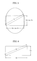
- Fig. 7 is a conceptual diagram of aspect ratio, for describing a second embodiment of the present invention.
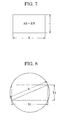
- Fig. 8 is a conceptual diagram of an image circle and image-taking range in the field of an image-formation optical system according to the second embodiment of the present invention.
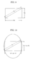
- Fig. 9 is a conceptual diagram of an image circle and image-taking range following conversion by a converter, according to the second embodiment of the present invention.
- Fig. 10 is a conceptual diagram of the effective range of image-taking unit, according to the second embodiment of the present invention.
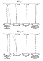
- Fig. 11 is a conceptual diagram of the display region of the output image at the time of showing, according to the second embodiment of the present invention.
- Figs. 12A and 12B are conceptual diagrams for describing aspect ratio conversion methods according to the second embodiment of the present invention.
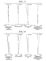
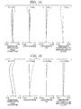
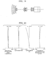
- Fig. 19 is a cross-sectional diagram illustrating the lens configuration at the wide-angle end before inserting the anamorphic converter, according to the first embodiment.
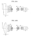
- Figs. 23A and 23B are diagrams illustrating the configuration of the second embodiment of the present invention.
- Fig. 23A is a cross-sectional diagram illustrating the lens configuration in the X direction with an anamorphic converter inserted
- Fig. 23B being a cross-sectional diagram illustrating the lens configuration in the Y direction with the anamorphic converter inserted.
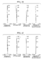
- Fig. 24 is a diagram of longitudinal aberration in the X direction at the wide angle end in a numerical example according to the second embodiment, wherein object distance is at infinity.
- Fig. 25 is a diagram of longitudinal aberration in the Y direction at the wide angle end in a numerical example according to the second embodiment, wherein object distance is at infinity.
- Fig. 28 is a diagram of longitudinal aberration in the X direction at the telephoto angle end in a numerical example according to the second embodiment, wherein object distance is at infinity.
- Fig. 29 is a diagram of longitudinal aberration in the Y direction at the telephoto end in a numerical example according to the second embodiment, wherein object distance is at infinity.
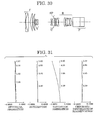
- Fig. 30 is a cross-sectional diagram illustrating the lens configuration at the wide-angle end before inserting the anamorphic converter, according to the second embodiment.
- Fig. 31 is a diagram of longitudinal aberration at the wide angle end in a numerical example according to the second embodiment, wherein object distance of the image-formation optical system is at infinity.
- Fig. 33 is a diagram of longitudinal aberration at the telephoto end in a numerical example according to the second embodiment, wherein object distance of the image-formation optical system is at infinity.
- FIG. 2 is a conceptual diagram of aspect ratio, for describing the present embodiment
- Fig. 3 is a conceptual diagram of an image circle and image-taking range in the field of an image-formation optical system according to the present embodiment
- Fig. 4 is a conceptual diagram of an image circle and image-taking range following conversion by a converter, according to the present embodiment
- Fig. 5 is a conceptual diagram of the effective range of image-taking unit, according to the first embodiment of the present invention
- Fig. 6 is a conceptual diagram of the display region of the output image at the time of showing, according to the first embodiment of the present invention.
- suitable aspect ratio conversion can be performed without vignetting, by means of appropriately stipulating conversion magnification with the following settings of conditions: 0.9 ⁇ (AR1 ⁇ ⁇ x) / (AR2 ⁇ ⁇ y) ⁇ 1.1 (AR2 2 + 1) ⁇ ⁇ y 2 / (AR1 2 + 1) > 1
- ⁇ x represents the focal distance magnification scale at an arbitrary cross-section X containing the optical axis of the anamorphic converter
- ⁇ y represents the focal distance magnification scale at a cross-section Y which is perpendicular to the cross-section X and contains the optical axis
- AR1 represents the aspect ratio of the image-taking range in the field of the image-formation optical system
- AR2 represents the aspect ratio at the effective range of the image-taking unit.
- Expression (1) is the condition for executing suitable aspect ratio conversion.
- Fig. 3 is a model diagram of the imaging range of the image-formation optical system
- Fig. 4 is a model diagram of the imaging range of the imaging unit.
- X1 is the horizontal length of effective screen dimensions of the imaging range for the field of the image-formation optical system
- Y1 is the vertical length thereof
- AR1 is the aspect ratio thereof
- X2 is the horizontal length for the imaging range of the imaging unit
- Y2 is the vertical length thereof
- AR2 is the aspect ratio thereof.
- Fig. 5 is a conceptual diagram of the imaging range following aspect ratio conversion with the anamorphic converter.
- Expression (2) shows the conditions for preventing vignetting accompanying aspect ratio conversion.
- the image circle is restricted by the effective diameter of the image-formation optical system side, and accordingly a conversion magnification smaller than 1 does not yield a wide angle. Rather, vignetting occurs at the periphery of the image.
- I3 > I2 must hold in order for the image following aspect ratio conversion to encompass the diagonal length of the imaging unit and to prevent vignetting.
- the image circle I1 of the image formation optical system can be considered to be approximately equal to the diagonal length I2 of the imaging unit, and accordingly, I3 2 / I1 2 > 1 and ⁇ y 2 ⁇ (AR2 2 + 1) ⁇ / (AR1 2 + 1) > 1
- Fig. 6 is a conceptual diagram of an output image at the time of showing.
- aspect ratio conversion opposite to that at the time of shooting must be performed, so as to return the aspect ratio to the original aspect ratio.
- the image circle of an image formation optical system changes depending on zooming, focusing, and aperture.
- the conditions given in Expression (2) are calculated based on conditions wherein the image circle is the smallest, enabling an arrangement wherein there is no vignetting even in the event that the left side of Expression (2) is smaller than 1 in the event that the image circle I1 can be ensured to be larger than the diagonal length I2 of the imaging unit by restricting the range of use of zooming, focusing, and aperture with the image-formation optical system.
- the configuration of the anamorphic converter for being removably inserted into the image-formation optical system for aspect ratio conversion can be suitably stipulated by setting conditions as: ⁇ a1 > 0 ⁇ a2 ⁇ 0 wherein the anamorphic converter has at least two anamorphic lenses a1 and a2 in that order from the object side, and wherein ⁇ a1 and ⁇ a2 represent the refractive power at an arbitrary cross-section X containing the optical axis or cross-section Y perpendicular to the cross-section X and containing the optical axis, for the anamorphic lenses a1 and a2, respectively.
- an anamorphic converter is disposed on the image side of the image-formation optical system as with the present embodiment, stipulating conditions for conversion magnification for the X and Y cross-sections containing the optical axis, and appropriately setting the lens configuration, enables realization of a built-in type anamorphic converter with excellent optical capabilities and no vignetting, optimal for digital cinematography in particular.
- FIG. 7 is a conceptual diagram of aspect ratio, for describing the present embodiment
- Fig. 8 is a conceptual diagram of an image circle and image-taking range in the field of an image-formation optical system according to the present embodiment
- Fig. 9 is a conceptual diagram of an image circle and image-taking range following conversion by a converter, according to the present embodiment
- Fig. 10 is a conceptual diagram of the effective range of image-taking unit, according to the present embodiment
- Fig. 11 is a conceptual diagram of the display region of the output image at the time of showing, according to the present embodiment
- Figs. 12A and 12B are conceptual diagrams for describing aspect ratio conversion methods according to the present embodiment.
- the vertical direction can be enlarged to obtain the intended aspect ratio by setting the following conditions: ⁇ a1 > 0 ⁇ a2 ⁇ 0 wherein the anamorphic converter has at least two anamorphic lenses a1 and a2 in that order from the object side, and wherein ⁇ a1 and ⁇ a2 represent the refractive power at an arbitrary cross-section X containing the optical axis or cross-section Y perpendicular to the cross-section X and containing the optical axis, for the anamorphic lenses a1 and a2, respectively.
- the anamorphic converter in order to realize an enlarging system for the cross-section Y direction alone, the anamorphic converter must be a tele-converter type with a positive-negative configuration from the object side of an anamorphic lens having positive power ⁇ a1 for the cross-section Y direction and an anamorphic lens having negative power ⁇ a2 for the cross-section Y direction.
- anamorphic converter disposed on the object side of the image-formation optical system in the event of converting a picture with an aspect ratio of 2.35:1 into a picture with an aspect ratio of 16:9, there are two conceivable ways, one being the method for enlarging in the vertical direction as shown in Fig. 12A, and the other being the method for compressing in the horizontal direction as shown in Fig. 12B.
- the anamorphic converter is disposed at the image side of the image-formation optical system, there is no vignetting with either method, but with the conventional techniques, a reduction system for compressing in the horizontal direction as shown in Fig.
- the anamorphic converter 12B requires that the field angle in the horizontal direction be ensured, resulting in the size of the anamorphic converter increasing. Also, the anamorphic converter has refractive power in the horizontal direction which is the longer dimensions of the effective screen, leading to deterioration of optical performance, such as deterioration in image-formation performance at the screen periphery, and distortion occurring. With the present invention, the vertical direction is enlarged as shown in Fig. 12A, so the anamorphic converter has refractive power in the vertical direction which is the shorter dimensions of the effective screen, thereby realizing a small and lightweight anamorphic converter wherein there is little deterioration of optical performance such as deterioration in image-formation performance at the screen periphery and distortion.
- suitable aspect ratio conversion can be performed by means of appropriately settings conditions as follows: 0.9 ⁇ (AR1 ⁇ ⁇ x) / (AR2 ⁇ ⁇ y) ⁇ 1.1 wherein ⁇ x represents the focal distance magnification scale at an arbitrary cross-section X containing the optical axis of the anamorphic converter, ⁇ y represents the focal distance magnification scale at a cross-section Y which is perpendicular to the cross-section X and contains the optical axis, AR1 represents the aspect ratio of the image-taking range in the field of the image-formation optical system, and AR2 represents the aspect ratio at the effective range of the image-taking unit disposed at the image side of the image-formation optical system.
- Expression (2-1) is the condition for executing suitable aspect ratio conversion.
- Fig. 8 is a model diagram of the imaging range of the image-formation optical system
- Fig. 9 is a model diagram of the imaging range of the imaging unit.
- Fig. 10 is a conceptual diagram of the imaging range following aspect ratio conversion with the anamorphic converter.
- Fig. 11 is a conceptual diagram of an output image at the time of showing.
- aspect ratio conversion opposite to that at the time of shooting must be performed, so as to return the aspect ratio to the original aspect ratio.
- a front converter type anamorphic converter which is small and has high optical performance, optimal for digital cinematography in particular, can be realized by stipulating conditions for conversion magnification of cross-sections X and Y containing the optical axis, and setting the lens configuration appropriately.
- Figs. 1A and 1B are diagrams illustrating the configuration of the first embodiment of the present invention.
- Fig. 1A is a cross-sectional diagram illustrating the lens configuration in the Y direction with an anamorphic converter inserted
- Fig. 1B is a cross-sectional diagram illustrating the lens configuration in the X direction with the anamorphic converter inserted.
- Fig. 1A is a cross-sectional diagram illustrating the lens configuration in the Y direction with an anamorphic converter inserted
- Fig. 1B is a cross-sectional diagram illustrating the lens configuration in the X direction with the anamorphic converter inserted.
- Fig. 13 is a diagram of longitudinal aberration in the X direction, in a numerical example according to the first embodiment wherein
- Fig. 16 is a diagram of longitudinal aberration in the Y direction, in a numerical
- Fig. 19 is a cross-sectional diagram illustrating the lens configuration at the wide-angle end before inserting the anamorphic converter, according to the first embodiment.
- Figs. 23A and 23B are diagrams illustrating the configuration of a second embodiment of the present invention.
- Fig. 23A is a cross-sectional diagram illustrating the lens configuration in the X direction with an anamorphic converter inserted
- Fig. 23B being a cross-sectional diagram illustrating the lens configuration in the Y direction with the anamorphic converter inserted.
- reference character F denotes a front lens group for positive refractive power serving as a first group.
- Reference character V denotes a variator for negative refractive power for variable magnification, serving as a second group, which changes magnification from wide-angle to telephoto by simply moving along the optical axis to the field side.
- Reference character C is a compensator for negative refractive power, serving as a third group, and non-linearly moves on the optical axis to the object side following a convex track, in order to correct image shifting accompanying variation of magnification.
- the variator V and compensator C make up the magnification variation system.
- reference character SP denotes the aperture (stop) and R denotes a relay group serving as a fourth group for fixed positive refractive power in variable magnification.
- Preference character P denotes a color separation prism or optical filter or the like, illustrated as a glass block in Fig. 1.
- a device including the first through fourth groups is defined as a lens device, a device having a color separation prism or optical filter and imaging device disposed closer to the object side from the fourth group is defined as a camera device, and a device having the lens device and camera device such that the lens device and camera device are capable of being detachably mounted is defined as an image-taking device.
- the fourth group has a generally afocal space A, with the anamorphic converter AN removably inserted in the space A.
- the anamorphic converter AN is configured of two cylindrical lenses a1 and a2, with each cylindrical lens having zero curvature in the X direction, only curvature in the Y direction.
- Figs. 23A and 23B are diagrams illustrating the configuration of a second embodiment of the present invention.
- Fig. 23A is a cross-sectional diagram illustrating the lens configuration in the X direction with an anamorphic converter inserted
- Fig. 23B is a cross-sectional diagram illustrating the lens configuration in the Y direction with the anamorphic converter inserted.
- Fig. 24 is a diagram of longitudinal aberration in the X direction at the wide angle end in a numerical example according to the second embodiment, wherein object distance is at infinity.
- Fig. 25 is a diagram of longitudinal aberration in the Y direction at the wide angle end in a numerical example according to the second embodiment, wherein object distance is at infinity.
- Fig. 24 is a diagram of longitudinal aberration in the X direction at the wide angle end in a numerical example according to the second embodiment, wherein object distance is at infinity.
- Fig. 25 is a diagram of longitudinal aberration in the Y direction at the wide angle end in a
- Fig. 28 is a diagram of longitudinal aberration in the X direction at the telephoto angle end in a numerical example according to the second embodiment, wherein object distance is at infinity.
- Fig. 29 is a diagram of longitudinal aberration in the Y direction at the telephoto end in a numerical example according to the second embodiment, wherein object distance is at infinity.
- Fig. 30 is a cross-sectional diagram illustrating the lens configuration at the wide-angle end before inserting the anamorphic converter, according to the second embodiment.
- Fig. 31 is a diagram of longitudinal aberration at the wide angle end in a numerical example according to the second embodiment, wherein object distance of the image-formation optical system is at infinity.
- Fig. 33 is a diagram of longitudinal aberration at the telephoto end in a numerical example according to the second embodiment, wherein object distance of the image-formation optical system is at infinity.
- reference character F denotes a front lens group for positive refractive power, serving as a first group.
- Reference character V denotes a variator for negative refractive power for variable magnification, serving as a second group, which changes magnification from wide-angle to telephoto by simply moving along the optical axis to the field side.
- Reference character C is a compensator for negative refractive power, serving as a third group, and.non-linearly moves on the optical axis to the object side following a convex track, in order to correct image shifting accompanying variation of magnification.
- the variator V and compensator C make up the magnification variation system.
- reference character SP denotes the aperture (stop) and R denotes a relay group serving as a fourth group for fixed positive refractive power in variable magnification.
- Preference character P denotes a color separation prism or optical filter or the like, illustrated as a glass block in Fig. 23A.
- Reference character AC denotes the anamorphic converter according to the present invention.
- a device including the first through fourth groups is defined as a lens device, a device having a color separation prism or optical filter and imaging device disposed closer to the object side from the fourth group is defined as a camera device, and a device having the lens device and camera device such that the lens device and camera device are capable of being detachably mounted is defined as an image-taking device.
- the anamorphic converter AC according to the present invention as shown in Figs. 23A and 23B uses two cylindrical lenses having refractive power only in the cross-section Y direction, forming an afocal converter (anamorphic converter) having different magnifications at the cross-section X and the cross-section Y.
- an afocal converter anamorphic converter
- a tele-converter configuration is used wherein a cylindrical lens having positive power ⁇ a1 in the cross-section Y direction and a cylindrical lens having negative power ⁇ a2 in the cross-section Y direction are disposed in order from the object side, as indicated in the numerical examples of the present embodiment.
Landscapes
- Physics & Mathematics (AREA)
- General Physics & Mathematics (AREA)
- Optics & Photonics (AREA)
- Lenses (AREA)
Applications Claiming Priority (2)
| Application Number | Priority Date | Filing Date | Title |
|---|---|---|---|
| JP2004027496A JP4401802B2 (ja) | 2004-02-04 | 2004-02-04 | カメラ |
| JP2004027496 | 2004-02-04 |
Publications (1)
| Publication Number | Publication Date |
|---|---|
| EP1566681A1 true EP1566681A1 (en) | 2005-08-24 |
Family
ID=34709072
Family Applications (1)
| Application Number | Title | Priority Date | Filing Date |
|---|---|---|---|
| EP05250569A Withdrawn EP1566681A1 (en) | 2004-02-04 | 2005-02-02 | Anamorphic converter, lens device using the same, and image-taking device using the same |
Country Status (3)
| Country | Link |
|---|---|
| US (1) | US7113344B2 (ja) |
| EP (1) | EP1566681A1 (ja) |
| JP (1) | JP4401802B2 (ja) |
Cited By (4)
| Publication number | Priority date | Publication date | Assignee | Title |
|---|---|---|---|---|
| GB2430272A (en) * | 2005-09-16 | 2007-03-21 | Raytheon Co | Optical system having an anamorphic lens |
| WO2009134602A2 (en) | 2008-04-30 | 2009-11-05 | Symbol Technologies, Inc. | Imaging system having anamorphic magnification |
| GB2513993A (en) * | 2013-04-04 | 2014-11-12 | Cooke Optics Ltd | Anamorphic objective lens |
| US9341827B2 (en) | 2013-04-04 | 2016-05-17 | Cooke Optics Limited | Anamorphic objective lens |
Families Citing this family (14)
| Publication number | Priority date | Publication date | Assignee | Title |
|---|---|---|---|---|
| FR2884338B1 (fr) * | 2005-04-11 | 2007-10-19 | Valeo Vision Sa | Procede, dispositif et camera pour la detection d'objets a partir d'images numeriques |
| JP4790399B2 (ja) * | 2005-12-09 | 2011-10-12 | コニカミノルタオプト株式会社 | 超広角撮像光学系、超広角撮像レンズ装置及び撮像装置 |
| JP4511502B2 (ja) | 2006-09-30 | 2010-07-28 | 日立ビアメカニクス株式会社 | 基板露光装置 |
| DE102008021341B4 (de) * | 2008-04-29 | 2015-05-07 | Carl Zeiss Ag | Anamorphotisches Abbildungsobjektiv |
| EP2687888A4 (en) * | 2011-03-17 | 2014-09-03 | Navarro Alfredo Valles | ANAMORPHIC LENS |
| JP5929478B2 (ja) * | 2011-06-17 | 2016-06-08 | セイコーエプソン株式会社 | 投写光学系及びこれを備えるプロジェクター |
| JP2013003566A (ja) * | 2011-06-22 | 2013-01-07 | Seiko Epson Corp | 投写光学系及びこれを備えるプロジェクター |
| JP5621723B2 (ja) * | 2011-07-04 | 2014-11-12 | セイコーエプソン株式会社 | 投写光学系及びこれを備えるプロジェクター |
| JP5533798B2 (ja) | 2011-07-04 | 2014-06-25 | セイコーエプソン株式会社 | 投写光学系及びこれを備えるプロジェクター |
| JP2013029569A (ja) * | 2011-07-27 | 2013-02-07 | Seiko Epson Corp | 投写光学系及びこれを備えるプロジェクター |
| JP5982780B2 (ja) * | 2011-10-27 | 2016-08-31 | セイコーエプソン株式会社 | 投写光学系及びこれを備えるプロジェクター |
| US9239449B2 (en) * | 2013-04-04 | 2016-01-19 | Cooke Optics Ltd. | Anamorphic objective zoom lens |
| US9841538B2 (en) * | 2013-04-04 | 2017-12-12 | Cooke Optics Ltd. | Anamorphic objective zoom lens |
| US10401634B1 (en) | 2018-02-12 | 2019-09-03 | Panavision International, L.P. | Attachment producing anamorphic effect |
Citations (3)
| Publication number | Priority date | Publication date | Assignee | Title |
|---|---|---|---|---|
| US3751136A (en) * | 1970-09-01 | 1973-08-07 | K Kirchhoff | Variable focal length anamorphotic cinecamera systems |
| US5668666A (en) * | 1995-01-05 | 1997-09-16 | Nikon Corporation | Zoom lens with an anamorphic converter |
| JP2001108899A (ja) * | 1999-10-08 | 2001-04-20 | Sony Corp | ズームレンズおよび画像変換装置 |
Family Cites Families (7)
| Publication number | Priority date | Publication date | Assignee | Title |
|---|---|---|---|---|
| JPH0213916A (ja) | 1988-07-01 | 1990-01-18 | Matsushita Electric Ind Co Ltd | コンバージョンレンズ |
| EP0374845B1 (en) | 1988-12-23 | 1995-04-12 | Fujitsu Limited | Method and apparatus for driving a liquid crystal display panel |
| JP2823128B2 (ja) | 1989-06-23 | 1998-11-11 | 株式会社日立製作所 | アナモフィックアタッチメント |
| JPH05188271A (ja) | 1992-01-14 | 1993-07-30 | Canon Inc | アナモフィック系を有した撮影装置 |
| JPH0682691A (ja) | 1992-08-31 | 1994-03-25 | Canon Inc | アナモフィックコンバーター |
| JP3013721B2 (ja) * | 1994-10-20 | 2000-02-28 | キヤノン株式会社 | デジタル画像形成手段を有した光学装置 |
| US6995920B2 (en) * | 2003-04-04 | 2006-02-07 | Canon Kabushiki Kaisha | Anamorphic converter |
-
2004
- 2004-02-04 JP JP2004027496A patent/JP4401802B2/ja not_active Expired - Fee Related
-
2005
- 2005-02-02 EP EP05250569A patent/EP1566681A1/en not_active Withdrawn
- 2005-02-03 US US11/050,391 patent/US7113344B2/en not_active Expired - Fee Related
Patent Citations (3)
| Publication number | Priority date | Publication date | Assignee | Title |
|---|---|---|---|---|
| US3751136A (en) * | 1970-09-01 | 1973-08-07 | K Kirchhoff | Variable focal length anamorphotic cinecamera systems |
| US5668666A (en) * | 1995-01-05 | 1997-09-16 | Nikon Corporation | Zoom lens with an anamorphic converter |
| JP2001108899A (ja) * | 1999-10-08 | 2001-04-20 | Sony Corp | ズームレンズおよび画像変換装置 |
Non-Patent Citations (1)
| Title |
|---|
| PATENT ABSTRACTS OF JAPAN vol. 2000, no. 21 3 August 2001 (2001-08-03) * |
Cited By (7)
| Publication number | Priority date | Publication date | Assignee | Title |
|---|---|---|---|---|
| GB2430272A (en) * | 2005-09-16 | 2007-03-21 | Raytheon Co | Optical system having an anamorphic lens |
| WO2009134602A2 (en) | 2008-04-30 | 2009-11-05 | Symbol Technologies, Inc. | Imaging system having anamorphic magnification |
| EP2294461A2 (en) * | 2008-04-30 | 2011-03-16 | Symbol Technologies, Inc. | Imaging system having anamorphic magnification |
| EP2294461A4 (en) * | 2008-04-30 | 2014-04-23 | Symbol Technologies Inc | IMAGING SYSTEM WITH ANAMORPHER MAGNIFICATION |
| GB2513993A (en) * | 2013-04-04 | 2014-11-12 | Cooke Optics Ltd | Anamorphic objective lens |
| US9341827B2 (en) | 2013-04-04 | 2016-05-17 | Cooke Optics Limited | Anamorphic objective lens |
| GB2513993B (en) * | 2013-04-04 | 2017-06-14 | Cooke Optics Ltd | Anamorphic objective lens |
Also Published As
| Publication number | Publication date |
|---|---|
| JP4401802B2 (ja) | 2010-01-20 |
| US20050168829A1 (en) | 2005-08-04 |
| JP2005221597A (ja) | 2005-08-18 |
| US7113344B2 (en) | 2006-09-26 |
Similar Documents
| Publication | Publication Date | Title |
|---|---|---|
| EP1566681A1 (en) | Anamorphic converter, lens device using the same, and image-taking device using the same | |
| US7095563B2 (en) | Anamorphic converter, lens system, and shooting system | |
| US7990624B2 (en) | Zoom lens and image pickup apparatus having the same | |
| JP4976867B2 (ja) | ズームレンズ及びそれを有する撮像装置 | |
| JP4630423B2 (ja) | ズームレンズ及びそれを用いた光学機器 | |
| JP4994796B2 (ja) | ズームレンズ及びそれを有する撮像装置 | |
| JP4046834B2 (ja) | 防振機能を有した変倍光学系 | |
| JP4789530B2 (ja) | ズームレンズ及びそれを有する撮像装置 | |
| US8264779B2 (en) | Zoom lens and image pickup apparatus including same | |
| JP2005215385A (ja) | ズームレンズ及びそれを有する撮像装置 | |
| JP2010160242A (ja) | ズームレンズ及びそれを有する撮像装置 | |
| JP2005221597A5 (ja) | ||
| JP4847091B2 (ja) | ズームレンズ及びそれを有する撮像装置 | |
| JP2003295057A (ja) | ズームレンズ及びそれを有する光学機器 | |
| JP2010160243A (ja) | ズームレンズ及びそれを有する撮像装置 | |
| JP4323584B2 (ja) | 防振機能を有した変倍光学系 | |
| JP5858761B2 (ja) | ズームレンズ及びそれを有する撮像装置 | |
| JP2003295053A (ja) | ズームレンズ及びそれを有する光学機器 | |
| JP3927730B2 (ja) | 防振機能を有した変倍光学系 | |
| JP2020030249A (ja) | ズームレンズ及びそれを有する撮像装置 | |
| JP2006227644A (ja) | 防振機能を有した変倍光学系 | |
| JP2004325566A (ja) | ズームレンズ | |
| JP2016212210A (ja) | 光学系及びそれを有する撮像装置 | |
| JP2019174510A (ja) | ズームレンズ及び撮像装置 | |
| JP2005024844A (ja) | ズームレンズ及びそれを有する撮像装置 |
Legal Events
| Date | Code | Title | Description |
|---|---|---|---|
| PUAI | Public reference made under article 153(3) epc to a published international application that has entered the european phase |
Free format text: ORIGINAL CODE: 0009012 |
|
| AK | Designated contracting states |
Kind code of ref document: A1 Designated state(s): AT BE BG CH CY CZ DE DK EE ES FI FR GB GR HU IE IS IT LI LT LU MC NL PL PT RO SE SI SK TR |
|
| AX | Request for extension of the european patent |
Extension state: AL BA HR LV MK YU |
|
| 17P | Request for examination filed |
Effective date: 20060126 |
|
| AKX | Designation fees paid |
Designated state(s): DE FR GB NL |
|
| STAA | Information on the status of an ep patent application or granted ep patent |
Free format text: STATUS: THE APPLICATION HAS BEEN WITHDRAWN |
|
| 18W | Application withdrawn |
Effective date: 20090602 |