EP1564482B1 - Kfz-Scheinwerfer nach dem Projektionsprinzip umfassend eine Blende aus lichtdurchlässigem Material - Google Patents
Kfz-Scheinwerfer nach dem Projektionsprinzip umfassend eine Blende aus lichtdurchlässigem Material Download PDFInfo
- Publication number
- EP1564482B1 EP1564482B1 EP05290257A EP05290257A EP1564482B1 EP 1564482 B1 EP1564482 B1 EP 1564482B1 EP 05290257 A EP05290257 A EP 05290257A EP 05290257 A EP05290257 A EP 05290257A EP 1564482 B1 EP1564482 B1 EP 1564482B1
- Authority
- EP
- European Patent Office
- Prior art keywords
- screen
- headlight
- occulting
- lighting
- zone
- Prior art date
- Legal status (The legal status is an assumption and is not a legal conclusion. Google has not performed a legal analysis and makes no representation as to the accuracy of the status listed.)
- Expired - Lifetime
Links
- 239000012780 transparent material Substances 0.000 title claims abstract description 12
- 239000000463 material Substances 0.000 claims abstract description 21
- 239000011521 glass Substances 0.000 claims abstract description 6
- 230000003287 optical effect Effects 0.000 claims description 14
- 238000000151 deposition Methods 0.000 claims description 8
- 238000004381 surface treatment Methods 0.000 claims description 3
- 238000005286 illumination Methods 0.000 abstract description 26
- 230000002411 adverse Effects 0.000 abstract description 2
- 230000001105 regulatory effect Effects 0.000 description 16
- 230000008021 deposition Effects 0.000 description 6
- 230000002093 peripheral effect Effects 0.000 description 3
- 229910052782 aluminium Inorganic materials 0.000 description 2
- XAGFODPZIPBFFR-UHFFFAOYSA-N aluminium Chemical compound [Al] XAGFODPZIPBFFR-UHFFFAOYSA-N 0.000 description 2
- 230000000694 effects Effects 0.000 description 2
- 241001644893 Entandrophragma utile Species 0.000 description 1
- VYPSYNLAJGMNEJ-UHFFFAOYSA-N Silicium dioxide Chemical compound O=[Si]=O VYPSYNLAJGMNEJ-UHFFFAOYSA-N 0.000 description 1
- 241001639412 Verres Species 0.000 description 1
- 239000000919 ceramic Substances 0.000 description 1
- 230000001276 controlling effect Effects 0.000 description 1
- 238000011161 development Methods 0.000 description 1
- 230000018109 developmental process Effects 0.000 description 1
- 238000010586 diagram Methods 0.000 description 1
- 238000004519 manufacturing process Methods 0.000 description 1
- 229910052751 metal Inorganic materials 0.000 description 1
- 239000002184 metal Substances 0.000 description 1
- 239000000203 mixture Substances 0.000 description 1
- 230000003071 parasitic effect Effects 0.000 description 1
- 238000005375 photometry Methods 0.000 description 1
- 239000005373 porous glass Substances 0.000 description 1
- 230000002028 premature Effects 0.000 description 1
- 230000000750 progressive effect Effects 0.000 description 1
- 230000001681 protective effect Effects 0.000 description 1
- 239000000741 silica gel Substances 0.000 description 1
- 229910002027 silica gel Inorganic materials 0.000 description 1
- 239000005341 toughened glass Substances 0.000 description 1
- 230000007704 transition Effects 0.000 description 1
- 230000003313 weakening effect Effects 0.000 description 1
Images

Classifications
-
- F—MECHANICAL ENGINEERING; LIGHTING; HEATING; WEAPONS; BLASTING
- F21—LIGHTING
- F21S—NON-PORTABLE LIGHTING DEVICES; SYSTEMS THEREOF; VEHICLE LIGHTING DEVICES SPECIALLY ADAPTED FOR VEHICLE EXTERIORS
- F21S41/00—Illuminating devices specially adapted for vehicle exteriors, e.g. headlamps
- F21S41/60—Illuminating devices specially adapted for vehicle exteriors, e.g. headlamps characterised by a variable light distribution
- F21S41/68—Illuminating devices specially adapted for vehicle exteriors, e.g. headlamps characterised by a variable light distribution by acting on screens
- F21S41/683—Illuminating devices specially adapted for vehicle exteriors, e.g. headlamps characterised by a variable light distribution by acting on screens by moving screens
- F21S41/695—Screens rotating around a vertical axis
-
- F—MECHANICAL ENGINEERING; LIGHTING; HEATING; WEAPONS; BLASTING
- F21—LIGHTING
- F21S—NON-PORTABLE LIGHTING DEVICES; SYSTEMS THEREOF; VEHICLE LIGHTING DEVICES SPECIALLY ADAPTED FOR VEHICLE EXTERIORS
- F21S41/00—Illuminating devices specially adapted for vehicle exteriors, e.g. headlamps
- F21S41/40—Illuminating devices specially adapted for vehicle exteriors, e.g. headlamps characterised by screens, non-reflecting members, light-shielding members or fixed shades
- F21S41/43—Illuminating devices specially adapted for vehicle exteriors, e.g. headlamps characterised by screens, non-reflecting members, light-shielding members or fixed shades characterised by the shape thereof
Definitions
- the present invention relates to a projector of the elliptical type for a motor vehicle.
- the present invention more particularly relates to a motor vehicle headlamp, comprising a light source, an elliptical reflector whose first focus is located in the vicinity of the source, a convergent lens having a focal plane passes in the vicinity of a second focus of the reflector, and an occultation screen which is interposed axially, along the longitudinal optical axis of the projector, between the reflector and the lens, and which delimits a cutoff profile in the light beam emitted by the source to produce a beam Rainy day lighting regulation with an area of less illumination below the cut-off.
- the blackout screen constitutes a diaphragm whose edge forms the cutoff profile which is reproduced towards infinity, at the front of the vehicle, by the objective formed here by the lens, to form a lighting beam having a cut whose shape corresponds to the cutoff profile.
- the diaphragm reproduced by the lens makes it possible to obtain a darkness / clarity limit whose shape is perfectly defined according to the needs, with a sharpness or a desired blur.
- the regulatory beam for rainy weather lighting has the particularity of having a cut-off profile identical to that of a regulatory crossing beam and of having a zone of lower illumination which is situated below the cut-off, inside. of the lighting beam.
- the regulation imposes a weakening of the illumination below the cutoff profile and to the left of the longitudinal axis of the vehicle, in the case of a traffic on the right of the roadway.
- the zone of less illumination is intended to prevent drivers traveling on the opposite lane from being dazzled by the reflection of the light rays on the left side of the roadway between the two vehicles traveling in opposite directions, due to the wet condition of the vehicle. floor.
- the elliptical projector is generally intended to produce several regulatory lighting beams, in particular a conventional passing beam, since the lighting beam in rainy weather only corresponds to a particular traffic situation.
- the elliptical headlamp is provided with at least one movable occultation screen at several positions corresponding to several regulatory lighting beams, including the lighting beam in rainy weather.
- an occultation screen tilting about a horizontal transverse axis between a concealment position and a retracted position.
- This screen has a cutoff profile corresponding to a regulatory crossing beam and a transverse tab which is intended to form the area of lower illumination corresponding to the lighting beam in rainy weather.
- the occultation screen is movable between an active position in which the screen obscures part of the light rays emitted by the source so that the projector realizes a regulation light beam in rainy weather, and a retracted position in which the projector achieves another regulatory lighting beam.
- the tab is attached to the front of the screen and extends vertically upward. Therefore, it forms, in the lighting beam, a zone of less illumination that extends to the cut.
- the lighting beam obtained is not entirely satisfactory because the tongue deteriorates the quality of the lighting beam near the cut.
- defocused tab creates an imbalance on the mobile screen.
- the presence of this unbalance is particularly troublesome in a projector comprising a drum mounted to rotate about an axis inclined in the longitudinal plane, such as the conical drum which is described in the document FR-A-2815310 .
- the unbalance effect produced by the defocused tab on the pivoting part can be a source of vibration in the projector and it can cause premature wear of the motor that drives the drum.
- the presence of the defocused tab may cause congestion problems inside the projector, including mechanical interference, depending on the different angular positions occupied by the blackout screen.
- the invention aims to remedy these drawbacks by proposing a simple, effective and economical solution.
- the invention proposes a projector of the type described above, characterized in that the occultation screen comprises at least a generally transverse portion which is made of transparent material and which extends above the cutoff profile , in that this transparent portion of the occultation screen comprises a zone of lesser transparency which forms the zone of less illumination in the regulatory lighting beam.
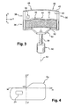
- FIG. 1 and 2 there is shown a projector 10 for a motor vehicle that is made according to the teachings of the invention.
- the projector 10 comprises a light source 12 and a reflector 14 of the elliptical type.
- the light source 12 is arranged globally at the first focus of the elliptical reflector 14.
- a longitudinal optical axis A1 which is oriented from the rear towards the front, in the direction of illumination of the projector 10 is defined in a nonlimiting manner, which corresponds to an orientation of the left towards the right by considering the figure 1 .
- the projector 10 comprises at the front a lens holder 16 which is fixed on the peripheral front axial end edge 15 of the reflector 14.
- a convergent lens 18 is mounted in the opening formed at the forward axial end of the lens holder 16.
- the lens 18 is partially shown in the figures.
- the focal plane of the lens 18 is located generally in the vicinity of a second focus of the reflector 14.
- the reflector 14 and the lens holder 16 here constitute a frame of the projector 10.
- the projector 10 may further comprise a housing (not shown) closing the frame and be protected by a protective glass (not shown).
- the projector 10 comprises a fixed screen, which will be called mask 20, shaped curved plate.
- the mask 20 is fixed rigidly to the frame, here by means of two transverse fixing lugs 22, 24.
- Each fixing lug 22, 24 is in this case clamped axially between a portion of the front peripheral edge 15 of the reflector 14 and a portion of the peripheral edge. 26 vis-à-vis the lens holder 16.
- the mask 20 has a vertical generatrix in the form of a circular arc, whose center of curvature is arranged on the optical axis A1 at the front of the projector 10.
- the curve profile of the mask 20, in horizontal axial section, follows globally the field curvature of the lens 18, and the mask 20 extends in the vicinity of the focal plane of the lens 18.
- the mask 20 preferably extends over the entire transverse width of the reflector 14, and it extends vertically mainly in the lower half of the reflector 14.
- the upper edge 28 of the mask 20 has a cutout 29 centered on the optical axis A1 whose transverse width corresponds generally to the transverse width of the focal zone useful for the production of the illumination beams.
- the projector 10 comprises an occultation screen 30 which is interposed axially, along the longitudinal optical axis A1, between the reflector 14 and the lens 18, and which delimits at least one cutoff profile 32, 34 in the beam light emitted by the source 12 in order to achieve a regulatory beam of lighting in rainy weather said rain beam Fp.
- the occulting screen 30 is arranged in front of the mask 20, so that it extends at least partly in the focal plane of the lens 18.
- the occultation screen 30 and the mask 20 are provided to cooperate together so as to form the rain beam Fp.
- the occulting screen 30 is provided to selectively obscure a portion of the light rays emitted above the upper edge of the cutout 29 of the mask 20.
- the occulting screen 30 is pivotally mounted about an axis A2 contained generally in a vertical longitudinal plane, and slightly inclined relative to the vertical direction by an angle between zero and forty-five degrees.
- the occultation screen 30 pivots here between a first angular position, which is represented on the figure 2 , in which the projector 10 carries the rain beam Fp, and a second angular position in which the projector 10 makes the passing beam Fc.
- the occultation screen 30 is made of transparent material.
- the occultation screen 30 is generally in the form of a curved transparent blade comprising a generator, along the axis of pivoting A2, in the shape of an arc of a circle, so that the curvature of the screen 30 generally follows the field curvature of the lens 18.
- the occultation screen 30 comprises an occulting lower portion 36 and an upper portion 38 which passes light rays emitted by the source 12.
- the occulting lower portion 36 is made here by depositing an opaque material, for example aluminum, on at least one face 40, 42 that is generally transverse to the screen 30.
- an opaque material for example aluminum
- the opaque material is deposited on the two generally transverse faces 40, 42 of the screen 30.
- rear transverse face 40 and front transverse face 42 of occultation screen 30 denote the respectively convex and concave faces of occultation screen 30, although these faces 40, 42 are not really transverse to the optical axis A1.
- the upper edge 44 of the occulting portion 36 draws the two cutoff profiles 32, 34 of the illumination beams Fp, Fc associated with the screen 30.
- a portion of the occulting portion 36 extends here below the height of the upper edge of the cutout 29 of the mask 20, so that no light ray can reach the lens 18 by passing between the upper edge of the cutout 29 and the lower edge of the occulting portion 36.
- the upper portion 38 of the occultation screen 30 extends generally vertically to the top of the useful focal zone, with respect to the lens 18, so that all the light rays used to construct the illumination beam projected by the lens 18 pass through the transparent upper portion 38.
- the occultation screen 30 can be geometrically divided into two angular sectors 46, 48, relative to the pivot axis A2, which are substantially of the same circumferential dimension.
- a first angular sector 46 has the cutoff profile 32 corresponding to the rain beam Fp and a second angular sector 48 has the cutoff profile 34 corresponding to the dipped beam Fc.
- the cutoff profile 32 of the first angular sector 46 is substantially centered on the optical axis A1.
- the first angular position corresponds to a so-called active position of the first angular sector 46 and to a so-called retracted position of the second angular sector 48, the projector 10 producing the rain beam Fp.
- the first angular sector 46 comprises a zone of lesser transparency 50 intended to form the zone of less illumination Z in the rain beam Fp.
- the zone of least transparency 50 is arranged on the front face 42 of the first angular sector 46, above the first cutoff profile 32.
- the zone of lesser transparency 50 comprises a deposition of opaque material, for example of the same nature as that which forms the occulting lower portion 36, of a specific density so as to pass a portion of the light rays which reach the zone of light. less transparency 50.
- the density of opaque material in the area of lesser transparency 50 must therefore be less than the density of opaque material arranged in the occulting portion 36.
- the zone of lesser transparency 50 creates in the rain beam Fp a zone Z1 having illumination of intensity less than the illumination of the adjacent zones, without producing a shadow zone extending up to the cutoff.
- the second angular sector 48 of the occultation screen 30 has a cut-off profile 34 corresponding to a passing beam Fc. Unlike the first angular sector 46, it is therefore devoid of a zone of less transparency.
- the cutoff profile 34 of the second angular sector 48 is substantially centered on the optical axis A1.
- the second angular position corresponds to a so-called active position of the second angular sector 48 and to a so-called retracted position of the first angular sector 46, the projector 10 producing the passing beam Fc.
- the occulting screen 30 is here provided, at its lower end 52, with a fixing plate 54 which extends in a radial plane, relative to the pivot axis A2, and which is fixed on the end free upper 56 of the drive shaft 58 of an electric motor 60.
- the drive shaft 58 here constitutes the pivot axis A2 of the occulting screen 30.
- the fixing plate 56 is made in one piece with the occulting screen 30.
- the projector 10 By controlling the pivoting of the occultation screen 30 towards one of its two determined angular positions, the projector 10 thus realizes either a rain beam Fp, or a passing beam Fc.
- the arrangement of the zone of least transparency 50 on the front face 42 of the screen 30 makes it possible to shift the zone of lesser transparency 50 forward of the thickness of the screen 30 relative to the focal plane of the screen 30.
- the lens 18 which is in the vicinity of the rear face 40 of the screen 30, so that the area of lesser transparency 50 is defocused and creates a zone of lesser illumination Z1 blurred outline. This makes it possible to obtain a relatively progressive transition of the illumination intensity between the zone of less illumination and the adjacent zone of the beam Fp in which the intensity of illumination is greater.
- the zone of least transparency 50 according to the invention makes it possible to precisely and easily control the photometric characteristics of the rain beam Fp.
- the quantity of light that is emitted towards the zone of lower illumination Z1 for example by choosing the density and / or the thickness of opaque material deposited in the zone of least transparency 50, and / or by drawing in the zone of least transparency 50 patterns of opaque material that partially let the light.
- each face 40, 42 of the occulting screen 30 It is not essential to deposit the opaque material on each face 40, 42 of the occulting screen 30 to make the lower occulting portion.
- the deposition of opaque material on both faces 40, 42 reduces the cutoff chromatism, that is to say the presence of a colored light in the vicinity of the cut in the lighting beam Fp, Fc which is due to the axial shift of the focal plane of the lens 18 according to the wavelength of the light rays considered.
- the zone of lesser transparency 50 can also be achieved by the deposition of opaque material on the two faces 40, 42 of the occultation screen, in order to limit the chromatic effects, especially on the periphery of the zone of less transparency 50.
- the layer of opaque material may be constituted by a metal deposit, for example based on aluminum, or by ink.
- the zone of lesser transparency 50 may be constituted by a substantially uniform deposit, or by a pattern of small points or patterns.
- the zone of lesser transparency 50 can be achieved by a treatment of the surface of the transparent material constituting the occultation screen 30, for example by frosting, or by making bumps or hollow.
- Surface treatment can to optimize the photometry of the rain beam Fp by deflecting the light rays received by the zone of lesser transparency 50 to a zone of the rain beam Fp requiring more light intensity.
- the invention applies to other types of occultation screens (not shown), in particular to an occultation screen tilting about a substantially transverse axis, such as those described in document FR-A-2831497 , or to a disk-like shading screen transverse to the optical axis A1 and pivotally mounted about a longitudinal axis.
- the occultation screen may be limited in height at the height of the cut edges 32, 34.
- it comprises a transparent portion in the form of a tooth or vertical transverse tab, which extends upwards from the cutoff edge 32 corresponding to the rain beam Fp.
- the free end of this transparent portion then comprises the deposition of opaque material forming the zone of lesser transparency 50.
- the tooth-shaped transparent portion may be made of semi-transparent ceramic.
- an occultation screen 30 which comprises a transparent upper portion traversed by all the light rays forming the illumination beam, is to avoid the presence of parasitic images of the edges of the transparent portion.
- the occulting screen 30 may be made of tempered glass, or a special glass mixture that may be suitable for the operating constraints of the projector 10, especially with regard to vibration and temperature.
- the occultation screen 30 may also be made of "porous glass", that is to say a type of glass obtained from a silica gel and having interstices to reduce its density.
- a type of material 30 makes it possible in particular to minimize the mass of the occultation screen 30, thus reducing its inertia, and it makes it possible to reduce the losses of light by glassy reflection, because of the low refractive index of this material.
- the inclination of the pivot axis A2 with respect to a vertical position makes it possible to limit the size of the concealment screen 30 in the projector 10. Moreover, thanks to this inclination, the angular sector 46, 48 which occupies its retracted position is lower than the angular sector 46, 48 which occupies its active position, so that the angular sector 46, 48 retracted is under the path of the light rays forming the illumination beam Fp, Fc.
- the invention has been described with an occultation screen 30 comprising two cut-off profiles 32, 34.
- the invention also applies to a projector 10 equipped with an occultation screen 30 comprising a single profile of cutoff, or more than two cutoff profiles.
Landscapes
- Engineering & Computer Science (AREA)
- General Engineering & Computer Science (AREA)
- Non-Portable Lighting Devices Or Systems Thereof (AREA)
- Glass Compositions (AREA)
- Overhead Projectors And Projection Screens (AREA)
Claims (11)
- Kraftfahrzeugscheinwerfer (10) mit einer Lichtquelle (12), einem Reflektor (14) vom ellipsoiden Typ, dessen erster Brennpunkt in der Nähe der Lichtquelle (12) liegt, einer Sammellinse (18), deren Brennebene in der Nähe eines zweiten Brennpunkts des Reflektors (14) verläuft, und einer Abschatterblende (30), die längs der optischen Längsachse (A1) des Scheinwerfers (10) axial zwischen dem Reflektor (14) und der Linse (18) eingefügt ist und das Profil einer Hell-Dunkel-Grenze in dem von der Lichtquelle (12) ausgesandten Lichtbündel zum Erzeugen eines vorschriftsmäßigen Schlechtwetterlichts (Fp) festlegt, das einen Bereich mit geringerer Lichtintensität (Z1) aufweist, der unter der Hell-Dunkel-Grenze liegt, wobei die Abschatterblende (30) zwischen einer aktiven Position, in der die Blende (30) einen Teil der von der Lichtquelle (12) ausgesandten Lichtstrahlen derart abschattet, dass der Scheinwerfer (10) ein vorschriftsmäßiges Schlechtwetterlicht (Fp) erzeugt, und einer abgesenkten Position beweglich ist, in welcher der Scheinwerfer (10) ein anderes vorschriftsmäßiges Lichtbündel (Fc) erzeugt,
dadurch gekennzeichnet, dass die Abschatterblende (30) wenigstens einen allgemein quer verlaufenden Abschnitt (38) aufweist, der aus lichtdurchlässigem Material ausgeführt ist und über dem Profil der Hell-Dunkel-Grenze (32) verläuft,
dass dieser lichtdurchlässige Abschnitt (38) der Abschatterblende (30) einen Bereich mit geringerer Lichtdurchlässigkeit (50) aufweist, der in dem vorschriftsmäßigen Lichtbündel (Fp) den Bereich mit geringerer Lichtintensität (Z1) bildet. - Scheinwerfer (10) nach dem vorhergehenden Anspruch,
dadurch gekennzeichnet, dass der Bereich mit geringerer Lichtdurchlässigkeit (50) eine Schicht aus lichtundurchlässigem Material auf wenigstens einer quer verlaufenden Seite (42) des lichtdurchlässigen Abschnitts (38) aufweist. - Scheinwerfer (10) nach Anspruch 1,
dadurch gekennzeichnet, dass der Bereich mit geringerer Lichtdurchlässigkeit (50) eine örtlich begrenzte Oberflächenbehandlung aufweist, die auf wenigstens einer quer verlaufenden Seite (40, 42) des lichtdurchlässigen Abschnitts (38) ausgeführt ist. - Scheinwerfer (10) nach einem der vorhergehenden Ansprüche,
dadurch gekennzeichnet, dass die Abschatterblende (30) vollständig aus lichtdurchlässigem Material ausgeführt ist und einen abschattenden Hauptteil (36) umfasst, der durch Auftragen einer Schicht aus lichtundurchlässigem Material auf wenigstens einer ihrer quer verlaufenden Seiten (40, 42) gebildet ist. - Scheinwerfer (10) nach dem vorhergehenden Anspruch,
dadurch gekennzeichnet, dass der abschattende Hauptteil (36) eine Schicht aus lichtundurchlässigem Material auf beiden quer verlaufenden Seiten (40, 42) der Abschatterblende (30) aufweist. - Scheinwerfer (10) nach einem der vorhergehenden Ansprüche,
dadurch gekennzeichnet, dass sich der lichtdurchlässige Abschnitt (38) allgemein in Breitenrichtung über die gesamte Länge der Hell-Dunkel-Grenze (32) erstreckt und allgemein in Höhenrichtung bis zur oberen Grenze des wirksamen Brennpunktsbereiches verläuft, so dass der überwiegende Teil des nicht abgeschatteten Lichtbündels zwangsläufig den lichtdurchlässigen Abschnitt (38) durchquert. - Scheinwerfer (10) nach einem der vorhergehenden Ansprüche,
dadurch gekennzeichnet, dass er eine als Maske (20) bezeichnete ortsfeste Abschatterblende umfasst, die mit der beweglichen Blende (30) in der aktiven Position solchermaßen zusammenwirkt, dass das vorschriftsmäßige Schlechtwetterlicht (Fp) gebildet wird. - Scheinwerfer (10) nach Anspruch 1 oder 7,
dadurch gekennzeichnet, dass die Abschatterblende (30) um eine allgemein in einer Längsebene enthaltene Achse (A2) herum schwenkbar ist, und dass sich die Schwenkachse (A2) in einer Richtung erstreckt, die bezüglich der Vertikalen in einem Winkel geneigt ist, der allgemein zwischen 0 bis 45 Grad liegt. - Scheinwerfer (10) nach dem vorhergehenden Anspruch,
dadurch gekennzeichnet, dass die Abschatterblende (30) mehrere im Wesentlichen aneinander angrenzende Profillinien der Hell-Dunkel-Grenze (32, 34) aufweist, die jeweils mehreren vorschriftsmäßigen Lichtbündeln (Fp, Fc) entsprechen. - Scheinwerfer (10) nach dem vorhergehenden Anspruch in Verbindung mit Anspruch 4,
dadurch gekennzeichnet, dass die Abschatterblende (30) einstückig aus einem lichtdurchlässigen Material ausgeführt ist und sie allgemein die Form eines auf die Schwenkachse (A2) zentrierten Rohrwinkelsektors hat. - Scheinwerfer (10) nach einem der vorhergehenden Ansprüche,
dadurch gekennzeichnet, dass das lichtdurchlässige Material Glas ist.
Applications Claiming Priority (2)
| Application Number | Priority Date | Filing Date | Title |
|---|---|---|---|
| FR0401490A FR2866413B1 (fr) | 2004-02-13 | 2004-02-13 | Projecteur elliptique equipe d'un ecran d'occultation en matiere transparente. |
| FR0401490 | 2004-02-13 |
Publications (2)
| Publication Number | Publication Date |
|---|---|
| EP1564482A1 EP1564482A1 (de) | 2005-08-17 |
| EP1564482B1 true EP1564482B1 (de) | 2008-05-14 |
Family
ID=34685026
Family Applications (1)
| Application Number | Title | Priority Date | Filing Date |
|---|---|---|---|
| EP05290257A Expired - Lifetime EP1564482B1 (de) | 2004-02-13 | 2005-02-04 | Kfz-Scheinwerfer nach dem Projektionsprinzip umfassend eine Blende aus lichtdurchlässigem Material |
Country Status (6)
| Country | Link |
|---|---|
| US (1) | US7455439B2 (de) |
| EP (1) | EP1564482B1 (de) |
| JP (1) | JP5165834B2 (de) |
| AT (1) | ATE395556T1 (de) |
| DE (1) | DE602005006635D1 (de) |
| FR (1) | FR2866413B1 (de) |
Families Citing this family (23)
| Publication number | Priority date | Publication date | Assignee | Title |
|---|---|---|---|---|
| EP1605202B1 (de) * | 2004-06-09 | 2016-10-05 | Valeo Vision | Multifunktionales Scheinwerfergerät |
| FR2891511B1 (fr) * | 2005-09-30 | 2008-01-04 | Valeo Vision Sa | Systeme d'adaptation de l'eclairage d'un vehicule en fonction d'une situation de route et procede mis en oeuvre par ce systeme. |
| FR2897415B1 (fr) * | 2006-02-14 | 2008-04-11 | Valeo Vision Sa | Projecteur d'eclairage pour vehicules automobiles. |
| US7810972B2 (en) * | 2006-10-13 | 2010-10-12 | Visteon Global Technologies, Inc. | Headlamp assembly having an adjustable light beam direction |
| JP2008135302A (ja) * | 2006-11-29 | 2008-06-12 | Stanley Electric Co Ltd | プロジェクタ型車両用灯具 |
| RU2441778C2 (ru) * | 2007-09-24 | 2012-02-10 | Фольксваген Аг | Система фар прожекторного типа для автомобилей |
| JP4997052B2 (ja) * | 2007-10-01 | 2012-08-08 | 株式会社小糸製作所 | 車両用前照灯 |
| DE102007050207A1 (de) * | 2007-10-20 | 2009-04-23 | Hella Kgaa Hueck & Co. | Projektionsscheinwerfer für Fahrzeuge |
| FR2924485B1 (fr) * | 2007-12-03 | 2013-08-16 | Valeo Vision | Procede d'adaptation automatique aux conditions de circulation d'un faisceau lumineux de module optique, et projecteur associe |
| JP5106177B2 (ja) * | 2008-02-27 | 2012-12-26 | 株式会社小糸製作所 | 車輌用前照灯 |
| JP5199781B2 (ja) * | 2008-08-11 | 2013-05-15 | 株式会社小糸製作所 | 車両用前照灯装置 |
| FR2940403B1 (fr) * | 2008-12-19 | 2014-01-17 | Valeo Vision Sas | Dispositif d'eclairage pour projecteur de vehicule assurant plusieurs fonctions d'eclairage ou une fonction variable avec une seule source lumineuse |
| JP5448615B2 (ja) * | 2009-07-14 | 2014-03-19 | 株式会社小糸製作所 | 車両用前照灯 |
| FR2960497B1 (fr) * | 2010-05-31 | 2012-07-13 | Valeo Vision | Module d'eclairage pour projecteur de vehicule automobile |
| DE102014100904A1 (de) * | 2014-01-27 | 2015-07-30 | Hella Kgaa Hueck & Co. | Beleuchtungsvorrichtung für Fahrzeuge |
| FR3022327B1 (fr) * | 2014-06-16 | 2016-06-10 | Valeo Vision | Module d'eclairage et/ou de signalisation rotatif |
| FR3022328B1 (fr) * | 2014-06-16 | 2016-06-10 | Valeo Vision | Module d'eclairage et/ou de signalisation rotatif |
| US10948148B2 (en) * | 2015-05-26 | 2021-03-16 | Lumileds Llc | Lighting device with multiple-focus mode |
| DE102015015360A1 (de) * | 2015-11-27 | 2017-06-01 | GM Global Technology Operations LLC (n. d. Ges. d. Staates Delaware) | Scheinwerfer für ein Kraftfahrzeug |
| KR101756012B1 (ko) * | 2016-04-15 | 2017-07-07 | 현대자동차주식회사 | 자동차의 바이펑션 헤드램프 |
| CN109996990B (zh) | 2016-10-14 | 2021-12-28 | 科思创德国股份有限公司 | 用于减少彩色边纹的装置 |
| CN109469882A (zh) * | 2017-09-07 | 2019-03-15 | 隆达电子股份有限公司 | 车灯总成 |
| FR3125104B1 (fr) | 2021-07-12 | 2023-06-30 | Valeo Vision | Module lumineux comprenant un élément à taux variable de transmission de lumière |
Family Cites Families (16)
| Publication number | Priority date | Publication date | Assignee | Title |
|---|---|---|---|---|
| FR2537249B1 (fr) * | 1982-12-02 | 1987-12-31 | Cibie Projecteurs | Projecteur a faisceau coupe a reflecteur elliptique pour vehicule automobile |
| FR2558236B1 (fr) * | 1984-01-12 | 1986-05-23 | Cibie Projecteurs | Perfectionnemens aux projecteurs automobiles a faisceau coupe |
| JPS6318703U (de) * | 1986-07-21 | 1988-02-06 | ||
| JPH046084Y2 (de) * | 1987-03-31 | 1992-02-20 | ||
| JPS63292501A (ja) * | 1987-05-26 | 1988-11-29 | 株式会社小糸製作所 | 車輌用前照灯 |
| DE19704467B4 (de) * | 1997-02-06 | 2006-07-20 | Automotive Lighting Reutlingen Gmbh | Fahrzeug-Scheinwerfer |
| DE19807153A1 (de) * | 1998-02-20 | 1999-08-26 | Bosch Gmbh Robert | Scheinwerfer für Fahrzeuge nach dem Projektionsprinzip |
| DE19860669B4 (de) * | 1998-12-29 | 2007-08-23 | Automotive Lighting Reutlingen Gmbh | Fahrzeugscheinwerfer nach dem Projektionsprinzip |
| IT1307677B1 (it) * | 1999-02-08 | 2001-11-14 | Magneti Marelli Spa | Proiettore per autoveicoli |
| JP3967048B2 (ja) * | 1999-10-05 | 2007-08-29 | 株式会社小糸製作所 | 車両用前照灯 |
| FR2815310B1 (fr) * | 2000-10-12 | 2003-02-21 | Valeo Vision | Projecteur pour vehicule automobile a ecran d'occultation mobile |
| JP2002289013A (ja) * | 2000-12-05 | 2002-10-04 | Stanley Electric Co Ltd | 車両用灯具 |
| JP2002184219A (ja) * | 2000-12-18 | 2002-06-28 | Koito Mfg Co Ltd | 車輌用前照灯 |
| DE60123370T2 (de) * | 2000-12-25 | 2007-08-23 | Stanley Electric Co. Ltd. | Fahrzeugscheinwerfer mit einer verstellbaren Blende und einer verstellbaren Reflektorfläche zur Erzeugung eines Abblend- und Fernlichtbündels |
| FR2831497B1 (fr) * | 2001-10-30 | 2004-07-09 | Valeo Vision | Dispositif d'eclairage de type elliptique pour vehicule automobile |
| US7036969B2 (en) * | 2003-12-04 | 2006-05-02 | Guide Corporation | Adverse weather headlamp system |
-
2004
- 2004-02-13 FR FR0401490A patent/FR2866413B1/fr not_active Expired - Fee Related
-
2005
- 2005-02-04 EP EP05290257A patent/EP1564482B1/de not_active Expired - Lifetime
- 2005-02-04 DE DE602005006635T patent/DE602005006635D1/de not_active Expired - Lifetime
- 2005-02-04 AT AT05290257T patent/ATE395556T1/de not_active IP Right Cessation
- 2005-02-09 US US11/054,231 patent/US7455439B2/en not_active Expired - Fee Related
- 2005-02-10 JP JP2005033754A patent/JP5165834B2/ja not_active Expired - Fee Related
Also Published As
| Publication number | Publication date |
|---|---|
| FR2866413B1 (fr) | 2006-06-30 |
| DE602005006635D1 (de) | 2008-06-26 |
| US20050180154A1 (en) | 2005-08-18 |
| ATE395556T1 (de) | 2008-05-15 |
| JP2005228747A (ja) | 2005-08-25 |
| JP5165834B2 (ja) | 2013-03-21 |
| EP1564482A1 (de) | 2005-08-17 |
| FR2866413A1 (fr) | 2005-08-19 |
| US7455439B2 (en) | 2008-11-25 |
Similar Documents
| Publication | Publication Date | Title |
|---|---|---|
| EP1564482B1 (de) | Kfz-Scheinwerfer nach dem Projektionsprinzip umfassend eine Blende aus lichtdurchlässigem Material | |
| EP1197387B1 (de) | Kraftfahrzeugscheinwerfer mit verstellbarer Blende | |
| EP2006605B1 (de) | Fahrzeugsscheinwerfer | |
| EP1308669A1 (de) | Kfz-Scheinwerfer nach dem Projektionsprinzip | |
| EP1746340B1 (de) | Optisches Modul für eine Kfz-Beleuchtungseinrichtung | |
| EP1279893B1 (de) | Kfz-Scheinwerfer nach dem Projektionprinzip mit um eine Querachse schwenkbaren Blenden | |
| EP0465330B1 (de) | Scheinwerfer mit mehreren Funktionen, insbesondere für Kraftfahrzeuge | |
| FR2657681A1 (fr) | Projecteur pour vehicules automobiles, dont la source de lumiere est une lampe de decharge de gaz. | |
| FR2824623A1 (fr) | Phare de vehicule a diagramme composite de distribution de lumiere | |
| FR2769071A1 (fr) | Projecteur de type elliptique a faisceau variable, notamment pour vehicule automobile | |
| EP0256930B1 (de) | Nebelscheinwerfer für Kraftfahrzeuge mit einer Transversalwendel | |
| EP1422471A2 (de) | Elliptischer Kfz-Scheinwerfer zur Erzeugung von verschiedenen Lichtbündeln | |
| EP0628765B1 (de) | Fahrzeugscheinwerfer mit einem ellipsoid-ähnlichen Reflektor | |
| EP3396237B1 (de) | Leuchtmodul für kraftfahrzeug | |
| EP2006604B1 (de) | Optisches Modul für Beleuchtungseinrichtung für Fahrzeuge | |
| EP1170546A1 (de) | Elliptischer Scheinwerfer mit Strahlmodifikation durch Bewegung optischer Elemente | |
| EP1170547B2 (de) | Elliptischer Scheinwerfer für eine Strassenbeleuchtung mit verbesserter Niedrig-Photometrie | |
| FR2895782A1 (fr) | Dispositif projecteur elliptique multifonctions avec element optique additionnel | |
| FR2808867A1 (fr) | Projecteur bi-fonction a source lumineuse unique et occulteur mobile pour vehicule automobile | |
| FR2765310A1 (fr) | Projecteur de vehicule automobile capable d'emettre, avec une source lumineuse unique, deux faisceaux differents | |
| FR2789474A1 (fr) | Projecteur du genre elliptique pour vehicule automobile, susceptible d'engendrer selectivement l'un parmi deux types de faisceaux | |
| EP1096196A1 (de) | Platzsparender Kraftfahrzeugsscheinwerfer, insbesondere Abblendlichtscheinwerfer | |
| EP1160504B1 (de) | Verfahren um den Abblendlichtstrahl eines Scheinwerfers an den Gegenverkehr anzupassen, Vorrichtung, Schablone und Scheinwerfer um dieses Verfahren durchzufÜhren | |
| FR2758606A1 (fr) | Projecteur de vehicule automobile, equipe d'un systeme perfectionne de dioptres mobiles | |
| FR2758607A1 (fr) | Projecteur bi-faisceau a source et miroir uniques pour vehicule automobile |
Legal Events
| Date | Code | Title | Description |
|---|---|---|---|
| PUAI | Public reference made under article 153(3) epc to a published international application that has entered the european phase |
Free format text: ORIGINAL CODE: 0009012 |
|
| AK | Designated contracting states |
Kind code of ref document: A1 Designated state(s): AT BE BG CH CY CZ DE DK EE ES FI FR GB GR HU IE IS IT LI LT LU MC NL PL PT RO SE SI SK TR |
|
| AX | Request for extension of the european patent |
Extension state: AL BA HR LV MK YU |
|
| 17P | Request for examination filed |
Effective date: 20060202 |
|
| AKX | Designation fees paid |
Designated state(s): AT BE BG CH CY CZ DE DK EE ES FI FR GB GR HU IE IS IT LI LT LU MC NL PL PT RO SE SI SK TR |
|
| 17Q | First examination report despatched |
Effective date: 20061124 |
|
| GRAP | Despatch of communication of intention to grant a patent |
Free format text: ORIGINAL CODE: EPIDOSNIGR1 |
|
| RIC1 | Information provided on ipc code assigned before grant |
Ipc: F21S 8/12 20060101AFI20071120BHEP Ipc: F21V 14/08 20060101ALI20071120BHEP Ipc: F21W 101/10 20060101ALI20071120BHEP |
|
| GRAS | Grant fee paid |
Free format text: ORIGINAL CODE: EPIDOSNIGR3 |
|
| GRAA | (expected) grant |
Free format text: ORIGINAL CODE: 0009210 |
|
| AK | Designated contracting states |
Kind code of ref document: B1 Designated state(s): AT BE BG CH CY CZ DE DK EE ES FI FR GB GR HU IE IS IT LI LT LU MC NL PL PT RO SE SI SK TR |
|
| REG | Reference to a national code |
Ref country code: GB Ref legal event code: FG4D Free format text: NOT ENGLISH |
|
| REG | Reference to a national code |
Ref country code: CH Ref legal event code: EP |
|
| REG | Reference to a national code |
Ref country code: IE Ref legal event code: FG4D |
|
| REF | Corresponds to: |
Ref document number: 602005006635 Country of ref document: DE Date of ref document: 20080626 Kind code of ref document: P |
|
| PG25 | Lapsed in a contracting state [announced via postgrant information from national office to epo] |
Ref country code: SI Free format text: LAPSE BECAUSE OF FAILURE TO SUBMIT A TRANSLATION OF THE DESCRIPTION OR TO PAY THE FEE WITHIN THE PRESCRIBED TIME-LIMIT Effective date: 20080514 |
|
| PG25 | Lapsed in a contracting state [announced via postgrant information from national office to epo] |
Ref country code: FI Free format text: LAPSE BECAUSE OF FAILURE TO SUBMIT A TRANSLATION OF THE DESCRIPTION OR TO PAY THE FEE WITHIN THE PRESCRIBED TIME-LIMIT Effective date: 20080514 Ref country code: ES Free format text: LAPSE BECAUSE OF FAILURE TO SUBMIT A TRANSLATION OF THE DESCRIPTION OR TO PAY THE FEE WITHIN THE PRESCRIBED TIME-LIMIT Effective date: 20080825 |
|
| NLV1 | Nl: lapsed or annulled due to failure to fulfill the requirements of art. 29p and 29m of the patents act | ||
| PG25 | Lapsed in a contracting state [announced via postgrant information from national office to epo] |
Ref country code: NL Free format text: LAPSE BECAUSE OF FAILURE TO SUBMIT A TRANSLATION OF THE DESCRIPTION OR TO PAY THE FEE WITHIN THE PRESCRIBED TIME-LIMIT Effective date: 20080514 Ref country code: PL Free format text: LAPSE BECAUSE OF FAILURE TO SUBMIT A TRANSLATION OF THE DESCRIPTION OR TO PAY THE FEE WITHIN THE PRESCRIBED TIME-LIMIT Effective date: 20080514 Ref country code: AT Free format text: LAPSE BECAUSE OF FAILURE TO SUBMIT A TRANSLATION OF THE DESCRIPTION OR TO PAY THE FEE WITHIN THE PRESCRIBED TIME-LIMIT Effective date: 20080514 |
|
| PG25 | Lapsed in a contracting state [announced via postgrant information from national office to epo] |
Ref country code: IS Free format text: LAPSE BECAUSE OF FAILURE TO SUBMIT A TRANSLATION OF THE DESCRIPTION OR TO PAY THE FEE WITHIN THE PRESCRIBED TIME-LIMIT Effective date: 20080914 |
|
| REG | Reference to a national code |
Ref country code: IE Ref legal event code: FD4D |
|
| PG25 | Lapsed in a contracting state [announced via postgrant information from national office to epo] |
Ref country code: LT Free format text: LAPSE BECAUSE OF FAILURE TO SUBMIT A TRANSLATION OF THE DESCRIPTION OR TO PAY THE FEE WITHIN THE PRESCRIBED TIME-LIMIT Effective date: 20080514 Ref country code: CZ Free format text: LAPSE BECAUSE OF FAILURE TO SUBMIT A TRANSLATION OF THE DESCRIPTION OR TO PAY THE FEE WITHIN THE PRESCRIBED TIME-LIMIT Effective date: 20080514 Ref country code: IE Free format text: LAPSE BECAUSE OF FAILURE TO SUBMIT A TRANSLATION OF THE DESCRIPTION OR TO PAY THE FEE WITHIN THE PRESCRIBED TIME-LIMIT Effective date: 20080514 Ref country code: DK Free format text: LAPSE BECAUSE OF FAILURE TO SUBMIT A TRANSLATION OF THE DESCRIPTION OR TO PAY THE FEE WITHIN THE PRESCRIBED TIME-LIMIT Effective date: 20080514 Ref country code: SE Free format text: LAPSE BECAUSE OF FAILURE TO SUBMIT A TRANSLATION OF THE DESCRIPTION OR TO PAY THE FEE WITHIN THE PRESCRIBED TIME-LIMIT Effective date: 20080814 |
|
| PG25 | Lapsed in a contracting state [announced via postgrant information from national office to epo] |
Ref country code: PT Free format text: LAPSE BECAUSE OF FAILURE TO SUBMIT A TRANSLATION OF THE DESCRIPTION OR TO PAY THE FEE WITHIN THE PRESCRIBED TIME-LIMIT Effective date: 20081014 Ref country code: SK Free format text: LAPSE BECAUSE OF FAILURE TO SUBMIT A TRANSLATION OF THE DESCRIPTION OR TO PAY THE FEE WITHIN THE PRESCRIBED TIME-LIMIT Effective date: 20080514 Ref country code: RO Free format text: LAPSE BECAUSE OF FAILURE TO SUBMIT A TRANSLATION OF THE DESCRIPTION OR TO PAY THE FEE WITHIN THE PRESCRIBED TIME-LIMIT Effective date: 20080514 |
|
| PLBE | No opposition filed within time limit |
Free format text: ORIGINAL CODE: 0009261 |
|
| STAA | Information on the status of an ep patent application or granted ep patent |
Free format text: STATUS: NO OPPOSITION FILED WITHIN TIME LIMIT |
|
| 26N | No opposition filed |
Effective date: 20090217 |
|
| PG25 | Lapsed in a contracting state [announced via postgrant information from national office to epo] |
Ref country code: BG Free format text: LAPSE BECAUSE OF FAILURE TO SUBMIT A TRANSLATION OF THE DESCRIPTION OR TO PAY THE FEE WITHIN THE PRESCRIBED TIME-LIMIT Effective date: 20080814 Ref country code: EE Free format text: LAPSE BECAUSE OF FAILURE TO SUBMIT A TRANSLATION OF THE DESCRIPTION OR TO PAY THE FEE WITHIN THE PRESCRIBED TIME-LIMIT Effective date: 20080514 |
|
| BERE | Be: lapsed |
Owner name: VALEO VISION Effective date: 20090228 |
|
| PG25 | Lapsed in a contracting state [announced via postgrant information from national office to epo] |
Ref country code: IT Free format text: LAPSE BECAUSE OF FAILURE TO SUBMIT A TRANSLATION OF THE DESCRIPTION OR TO PAY THE FEE WITHIN THE PRESCRIBED TIME-LIMIT Effective date: 20080514 |
|
| PG25 | Lapsed in a contracting state [announced via postgrant information from national office to epo] |
Ref country code: MC Free format text: LAPSE BECAUSE OF NON-PAYMENT OF DUE FEES Effective date: 20090228 |
|
| REG | Reference to a national code |
Ref country code: CH Ref legal event code: PL |
|
| GBPC | Gb: european patent ceased through non-payment of renewal fee |
Effective date: 20090204 |
|
| PG25 | Lapsed in a contracting state [announced via postgrant information from national office to epo] |
Ref country code: LI Free format text: LAPSE BECAUSE OF NON-PAYMENT OF DUE FEES Effective date: 20090228 Ref country code: CH Free format text: LAPSE BECAUSE OF NON-PAYMENT OF DUE FEES Effective date: 20090228 |
|
| PG25 | Lapsed in a contracting state [announced via postgrant information from national office to epo] |
Ref country code: BE Free format text: LAPSE BECAUSE OF NON-PAYMENT OF DUE FEES Effective date: 20090228 |
|
| PG25 | Lapsed in a contracting state [announced via postgrant information from national office to epo] |
Ref country code: GB Free format text: LAPSE BECAUSE OF NON-PAYMENT OF DUE FEES Effective date: 20090204 |
|
| PG25 | Lapsed in a contracting state [announced via postgrant information from national office to epo] |
Ref country code: GR Free format text: LAPSE BECAUSE OF FAILURE TO SUBMIT A TRANSLATION OF THE DESCRIPTION OR TO PAY THE FEE WITHIN THE PRESCRIBED TIME-LIMIT Effective date: 20080815 |
|
| PG25 | Lapsed in a contracting state [announced via postgrant information from national office to epo] |
Ref country code: LU Free format text: LAPSE BECAUSE OF NON-PAYMENT OF DUE FEES Effective date: 20090204 |
|
| PG25 | Lapsed in a contracting state [announced via postgrant information from national office to epo] |
Ref country code: HU Free format text: LAPSE BECAUSE OF FAILURE TO SUBMIT A TRANSLATION OF THE DESCRIPTION OR TO PAY THE FEE WITHIN THE PRESCRIBED TIME-LIMIT Effective date: 20081115 |
|
| PG25 | Lapsed in a contracting state [announced via postgrant information from national office to epo] |
Ref country code: TR Free format text: LAPSE BECAUSE OF FAILURE TO SUBMIT A TRANSLATION OF THE DESCRIPTION OR TO PAY THE FEE WITHIN THE PRESCRIBED TIME-LIMIT Effective date: 20080514 |
|
| PG25 | Lapsed in a contracting state [announced via postgrant information from national office to epo] |
Ref country code: CY Free format text: LAPSE BECAUSE OF FAILURE TO SUBMIT A TRANSLATION OF THE DESCRIPTION OR TO PAY THE FEE WITHIN THE PRESCRIBED TIME-LIMIT Effective date: 20080514 |
|
| REG | Reference to a national code |
Ref country code: FR Ref legal event code: PLFP Year of fee payment: 12 |
|
| REG | Reference to a national code |
Ref country code: FR Ref legal event code: PLFP Year of fee payment: 13 |
|
| REG | Reference to a national code |
Ref country code: DE Ref legal event code: R079 Ref document number: 602005006635 Country of ref document: DE Free format text: PREVIOUS MAIN CLASS: F21S0008120000 Ipc: F21S0041000000 |
|
| REG | Reference to a national code |
Ref country code: FR Ref legal event code: PLFP Year of fee payment: 14 |
|
| PGFP | Annual fee paid to national office [announced via postgrant information from national office to epo] |
Ref country code: DE Payment date: 20200211 Year of fee payment: 16 |
|
| PGFP | Annual fee paid to national office [announced via postgrant information from national office to epo] |
Ref country code: FR Payment date: 20200228 Year of fee payment: 16 |
|
| REG | Reference to a national code |
Ref country code: DE Ref legal event code: R119 Ref document number: 602005006635 Country of ref document: DE |
|
| PG25 | Lapsed in a contracting state [announced via postgrant information from national office to epo] |
Ref country code: DE Free format text: LAPSE BECAUSE OF NON-PAYMENT OF DUE FEES Effective date: 20210901 Ref country code: FR Free format text: LAPSE BECAUSE OF NON-PAYMENT OF DUE FEES Effective date: 20210228 |