EP1160504B1 - Verfahren um den Abblendlichtstrahl eines Scheinwerfers an den Gegenverkehr anzupassen, Vorrichtung, Schablone und Scheinwerfer um dieses Verfahren durchzufÜhren - Google Patents
Verfahren um den Abblendlichtstrahl eines Scheinwerfers an den Gegenverkehr anzupassen, Vorrichtung, Schablone und Scheinwerfer um dieses Verfahren durchzufÜhren Download PDFInfo
- Publication number
- EP1160504B1 EP1160504B1 EP01400959A EP01400959A EP1160504B1 EP 1160504 B1 EP1160504 B1 EP 1160504B1 EP 01400959 A EP01400959 A EP 01400959A EP 01400959 A EP01400959 A EP 01400959A EP 1160504 B1 EP1160504 B1 EP 1160504B1
- Authority
- EP
- European Patent Office
- Prior art keywords
- headlight
- light
- horizontal
- optical axis
- region
- Prior art date
- Legal status (The legal status is an assumption and is not a legal conclusion. Google has not performed a legal analysis and makes no representation as to the accuracy of the status listed.)
- Expired - Lifetime
Links
Images


Classifications
-
- F—MECHANICAL ENGINEERING; LIGHTING; HEATING; WEAPONS; BLASTING
- F21—LIGHTING
- F21S—NON-PORTABLE LIGHTING DEVICES; SYSTEMS THEREOF; VEHICLE LIGHTING DEVICES SPECIALLY ADAPTED FOR VEHICLE EXTERIORS
- F21S41/00—Illuminating devices specially adapted for vehicle exteriors, e.g. headlamps
- F21S41/60—Illuminating devices specially adapted for vehicle exteriors, e.g. headlamps characterised by a variable light distribution
- F21S41/62—Illuminating devices specially adapted for vehicle exteriors, e.g. headlamps characterised by a variable light distribution for adaptation between right-hand and left-hand traffic
-
- F—MECHANICAL ENGINEERING; LIGHTING; HEATING; WEAPONS; BLASTING
- F21—LIGHTING
- F21S—NON-PORTABLE LIGHTING DEVICES; SYSTEMS THEREOF; VEHICLE LIGHTING DEVICES SPECIALLY ADAPTED FOR VEHICLE EXTERIORS
- F21S41/00—Illuminating devices specially adapted for vehicle exteriors, e.g. headlamps
- F21S41/20—Illuminating devices specially adapted for vehicle exteriors, e.g. headlamps characterised by refractors, transparent cover plates, light guides or filters
- F21S41/28—Cover glass
Definitions
- the present invention relates generally to motor vehicle headlamps, and more particularly to the means to be used to enable a vehicle provided with crossing headlamps for a given direction of traffic (for example traffic on the right for continental Europe). to be able to drive in a country where traffic is in the opposite direction (eg traffic on the left for the United Kingdom) without dazzling drivers of vehicles traveling in the opposite direction.
- a given direction of traffic for example traffic on the right for continental Europe.
- traffic for example traffic on the right for continental Europe
- a passing beam for traffic on the right is typically defined by an upper "V" cut, consisting of a horizontal half-plane to the left of the road axis and a half-plane inclined upwards. approximately 15 ° from the horizontal to the right of the road axis.
- the horizontal half-cut on the left makes it possible not to dazzle drivers of vehicles traveling in the opposite direction, while the half-cut back to the right makes it possible to illuminate the aisle of the road and to guarantee the visibility distance to the right. . It is therefore understandable that, when a vehicle thus equipped circulates in a country where traffic is on the left of the road, the part of the beam located under the rising half-break will dazzle the drivers of the vehicles traveling in the opposite direction, which seriously compromises the safety of the traffic.
- a method for adapting a crossover beam having the features of the preamble of claim 1 is described in DE-A-4202762.
- the known solution if it answers the problem posed, that is to say to avoid the glare of the drivers traveling in the opposite direction during a change of direction of circulation, is however unsatisfactory in that it consists in obscuring a a significant part of the beam emitted by the headlamp, thus to reduce the luminous flux illuminating the road situated in front of the vehicle, and consequently to reduce the visual comfort of the driver during the night driving, and all the more so as this driver circulates in a direction of circulation to which he is less accustomed than the sense in which it circulates ordinarily, and that he may not have all his reflexes.
- Such a solution for occultation of a portion of the light beam can also be implemented in so-called "elliptical" projectors, in which a light source is placed at a first focus of a recuperating mirror and concentrator of the ellipsoidal type, the The luminous flux is thus concentrated in a luminous spot at the second focal point of the ellipsoidal mirror, which coincides with the object focus of a convergent lens, which then projects the desired illumination beam onto the road.
- elliptical projectors in which a light source is placed at a first focus of a recuperating mirror and concentrator of the ellipsoidal type, the The luminous flux is thus concentrated in a luminous spot at the second focal point of the ellipsoidal mirror, which coincides with the object focus of a convergent lens, which then projects the desired illumination beam onto the road.
- the cut is generated by a cover or screen placed in the vicinity of the object focus of the converging lens, which directly obscures the light spot.
- the cover or the screen it is known to design the cover or the screen so that it is variable geometry, that is to say that it can, by the operation of a button or an electrical control, reverse the right and left half-cuts in the beam to transform a V-cut beam for right-hand traffic into a V-cut beam for left-hand traffic.
- the present invention is placed in this context and its purpose is to avoid these drawbacks by proposing to modify the geometry of the imposed light beam. by changing the direction of traffic by means that are substantially as simple to implement and as inexpensive as the holiday caches described above, ie by affixing to certain zones of the protective glass of the headlamp a device such as that the light emitted by the headlamp and situated below the upgoing half-break, located by construction of one side of the light beam emitted by this headlamp for a given direction of circulation, is eliminated from the beam emitted by the headlamp in such a way that that the latter is no longer dazzling for drivers of vehicles traveling in the opposite direction when the vehicle thus equipped is subject to a reversal of the direction of movement, while retaining the entire luminous flux emitted by the projector.
- the method further comprises the step of horizontally deflecting the light rays passing through the second region of the mask surface to be located in the portion of the passing beam below the horizontal and distributed in this part of the passing beam.
- the present invention also relates to an adaptation device for implementing such a method, the device being intended to be interposed in the path of a portion of a light beam emitted by a vehicle crossing headlamp automobile having a light source emitting light rays to a reflecting mirror which returns them towards a protective glass, to form a passing beam having on both sides of an optical axis a substantially horizontal half-cut extending on one side of the optical axis and a half-cut above the horizontal extending on the other side of the optical axis, the device being adapted to adapt the portion situated above the horizontal of the light beam emitted by the headlamp when the vehicle is traveling in a reverse direction of traffic to that for which the headlamp has been designed.
- the adaptation device consists of a transparent material and deflector of light.
- the present invention also relates to a template for carrying out the method described above.
- the template defines the second region of the protective glass of the projector on which the adaptation device is to be arranged.
- the template according to the invention is adapted to the total shape of the protective glass of the crossing headlamp and it defines the second region of the protective glass of the headlamp on which must be arranged the adaptation device.
- the subject of the present invention is a passing headlamp for a motor vehicle, comprising a light source emitting light rays towards a reflector mirror which sends them back towards a protective glass to form a passing beam comprising on both sides other of an optical axis a substantially horizontal upper half-cut extending from one side of the optical axis and a half-cut above the horizontal extending from the other side of the axis optical, the passing beam being adapted to be adapted according to a method as described above.
- the protective glass of the projector is provided with a template as described above.
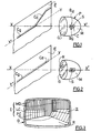
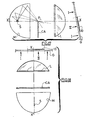
- FIG. 1 there is shown a projector P, having a reflector mirror M, a protective glass G, and a light source S, this projector being intended to equip a vehicle normally traveling in a traffic in right.
- the reflector M is for example parabolic, and the light source S is placed in its focus, so that the rays reflected by the reflector M are substantially parallel to the axis of the parabola, the protective glass G being then properly ridged to provide the desired photometric distribution for the beam emerging from the projector.
- the cut-off of the passing beam is obtained by the choice of the relative position of the light source S with respect to that of the reflector M, simultaneously with the use of masking elements intended to serve
- a lamp provided with an axially extending cross-light source in association with a parabolic reflector M it is known, for example, to use a substantially semi-circular dish.
- the left half-cut C g is horizontal, while the right half-cut C d is rising, and inclined by about 15 ° on the horizontal.
- the known solution is to stick on a given area of the protective glass G of each projector an opaque adhesive A, said "cache vacancier", to hide the beam portion located under the upgoing half-break C d , and to obtain a beam generally bounded by a cut almost flat, the two half-cut planes C d and C g being substantially merged, which avoids the glare problems mentioned above.
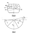
- the photometric distribution of the beam emerging from the headlamp is provided by properly formed ridges on the protective glass G, as shown in FIG. 3.
- the R portion is used to form the driving beam
- the LC portion to form the cross beam width
- the two sections of the PC portion to form the remote portion of the passing beam
- the two sections of the portion MD to form the medium-distance beam of the vehicle.
- the first region I consists of the parts LC, MD and a fraction of the part PC
- the second region II consists of the other fraction of the part PC, in the occurrence of the upper part of the right PC section (in Figure 3).
- the known solution is to stick on this region II of the protective glass an opaque adhesive, or a "cache vacancier", to stop the light rays passing through this region, to obtain a beam generally defined by a cut roughly flat, as shown on the screen E of Figure 2.
- Such a solution which consists of obscuring a significant part of the beam emitted by the projector, results in a decrease in the luminous flux illuminating the road located in front of the vehicle.
- such a modification is obtained by deflecting the light rays passing through region II of the protective glass so that they are on the one hand removed from the part of the light beam above the horizontal, and secondly used in the part of the light beam below the horizontal.
- the adaptation device designated as a whole by the reference 10, and replacing the "holiday cache" A of FIG. 2, is in the form of a deflection element of the radii. luminous which cross it, the deviation being directed downwards.
- the downward deflection of the path of the light rays passing through the second region of the protective glass of the headlamp is effected by a transparent and deflecting light element.
- such a transparent element and light deflection constituting the adaptation device comprises, when in place on the vehicle, a first substantially prismatic portion deviating the light downwards.
- the adaptation device comprises two substantially planar faces 12 and 14 forming between them a low angle ⁇ , for example less than 5 degrees, the vertex of this angle pointing upwards when it is in place on the vehicle's headlamp.
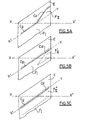
- the light beam emitted by the projector in the absence of an adaptation device when it is materialized on a screen E placed at a distance from the projector, comprises a portion F I below the horizontal and consisting of the light rays having passed through the first region I of the protective glass of the headlamp, and a part F II situated above the horizontal and below the right half-cut C d , and constituted light rays having passed through the second region II of the protective glass of the projector.
- the substantially prismatic portion of the adaptation device 10 may consist of a prism itself, as shown in FIG. 4, or it may be constituted by a Fresnel prism, as has been 6.
- a Fresnel prism In such a Fresnel prism, at least one of the faces, for example the face 12, is discontinuous and formed of horizontal ridges 16.
- the substantially prismatic portion of the adaptation device is presented in FIG. as a stack of elementary prisms, of the same angle at the vertex or having neighboring vertex angles, and for example evolving from one angle to the next of the same increment.
- the horizontal ridges 16 formed on the face 12 of the adaptation device may have a substantially triangular profile, as shown in FIG. 7A, or a substantially curvilinear profile, as has been shown in FIG. Figure 7B.
- the beam obtained can be further improved by means of the adaptation device which has just been described. Indeed, we see in Figure 5B that the light beam has a place receiving both parts F I and F II ', this superposition may be detrimental to the homogeneity of the resulting beam.
- the invention is also planned to horizontally deflect the light rays passing through the second region II of the surface of the protective glass G so that they are located in the part of the passing beam F I situated below the horizontal and that they are distributed in this part of the passing beam.
- the vertical striations 18 may be have a substantially prismatic profile, as shown in Figure 7B, the faces of the prismatic portions being slightly curvilinear, or they may have a purely curvilinear profile, as shown in Figures 7B and 7C.
- the light rays passing through the adaptation device will undergo, in addition to the downward vertical deviation due to the prismatic part just described, a horizontal deflection whose amplitude will be fixed by the profile of the Vertical streaks 18.
- the adaptation device 10 when the adaptation device 10 is put in place on the second region II of the projector glass, the part F II of the light beam is on the one hand deviated downwards, thanks to the substantially prismatic portion of the adapter device, and is further diverted and distributed horizontally, so as to occupy the position shown in F II ", as shown in Figure 5C.
- the adaptation device 10 thus comprises on one face horizontal streaks 16 such as those shown in Figures 7A or 7B, and vertical streaks such as those shown in Figures 7B or 7C.
- this modification of the geometry of the beam is performed only on the undesirable part of the beam, preserving intact the part of the beam that will not interfere with other users.
- the half-cut C g is not affected by the method or the device according to the present invention, only the portion F II of the beam located under the half-cut C d being adapted to fit at the level of the half-cut C g .
- the adaptation device according to the present invention is thus arranged only on a portion of the protective glass, to deflect vertically and horizontally only a portion of the light beam emitted by the projector, in the manner of the holiday cache of the prior art.
- the present invention applies without change to crossing headlamps, provided with reflecting mirrors M defining by themselves the cut-off beam and ice G striated, the location of the ice streaked G where to deposit the adaptation device 10 resulting from the geometry of the streaks of the ice G.
- the same advantages are obtained, namely simplicity of implementation, conservation of the entire luminous flux emitted by the projector, and compliance with the photometry requirements of the beam thus modified .
- the reflector M defines by itself the cut-off beam and of which the protective glass is smooth, ie non-deviating or weakly deviating, it is very simple to determine the second region II of the protective glass through which the light rays which constitute the F II portion situated above the horizontal and below the right half-cut C d , in the absence of an adaptation device according to the present invention, pass.
- the reflector mirror M of the headlamp itself defines the cut-off beam and comprises, by construction, zones marked 1, 2, 3, 4 and 5 in FIG. 2 corresponding to the two sections sections of the MD part to form the medium-distance beam of the vehicle, the zones 3 and 4 corresponding to the two sections of the PC part to form the remote portion of the passing beam, and the area 5 corresponding to the LC portion to form the width of the passing beam.
- These zones give rise to reflected rays constituting the crossing light beam portions marked respectively by F 1 , F 2 , F 3 , F 4 and F 5 in FIG. 11.
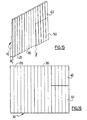
- FIGS. 12A and 12B show a front view of the smooth windows G R and G L of headlamps whose reflector defines the cut-off beam and which is fitted to a motor vehicle, these lenses G R and G L being each provided with a 10 R and 10 L matching device respectively, more particularly shown in Figures 13A and 13B.
- 12A and 12B show that the adaptation devices 10 R and 10 L are arranged on the smooth ice differently depending on whether the right headlamp or the left headlamp of the vehicle is considered.
- the present invention also provides a laying template, such as those shown in FIGS. 14B for projectors whose lenses G R and G L are shown in Figures 12A and 12B.
- FIGS. 14A and 14B show that each template 11 R and 11 L is adapted to the total shape of the protective glass of the crossing headlight for which it is intended, and that it delimits the second region of the protective glass the one on which the adaptation device is to be affixed. It is then easy for the user to set up, without risk of error, the adaptation devices 10 R and 10 L to a change of direction of circulation.
- the template simply delimits the region of the protective glass of the projector on which the adaptation device is to be arranged.
- a template may consist of the indication of the distance X or Y of the outer edge of the ice to which it is appropriate to affix the adaptation device.
- the template may also consist of markers such as highlights, light ribs, silk screen printing, etc. on the projector glass.
- the ice-cream G can be more or less inclined with respect to the vertical, more or less distant from the light source or the reflecting mirror, from so that the adaptation device that has just been described may provide only an imperfect adaptation. We can then realize such an adaptation device as shown in Figures 15 and 16.
- the adaptation device 10 may comprise several sections, in this case sections 20, 30, 40 and 50, each being made according to one of the embodiments described above.
- section 20 may consist of triangular-profile streaks, as in FIG. 7A, section 30 of curvilinear profile striations, as in FIG. 7C, and sections 40 and 50 of substantially prismatic profile streaks, such as FIG. in Figure 7B.
- the angle at the top of the downward deviating portion may vary from section to section, for example between sections 40 and 50.
- the downward deflecting portion of the adapter shown in FIG. 15 may be in the form of a Fresnel prism, as shown in FIGS. 6 and 9.
- the present invention may also receive another application for so-called "elliptical" projectors.
- a light source S is placed at a first focus of a mirror M recuperator and concentrator of the ellipsoidal kind, the light flux thus being concentrated in a light spot at the second focus of the ellipsoidal mirror, the light spot having an appropriate distribution of light within this spot.
- the second focus of the ellipsoidal mirror coincides with the object focal point F L of a convergent lens L, which thus projects the desired illumination beam onto the road.
- a cache CA retractable or fixed, allows, in known manner, to occult a portion of the light spot in the vicinity of the focus F L , so that the lens L projects on the road a passing beam, delimited by two half -cuts as shown in Figure 5A.
- the surface of the protective glass of the headlamp determines the different regions through which the light rays pass. corresponding to different parts of the passing beam, and in particular, as shown in Figures 17 and 18, at least a first region I through which pass the light rays corresponding to the part F I of the passing beam located below the horizontal, and at least a second region II through which light rays corresponding to the part F II of the passing beam located between the horizontal Y'Y and the half-cut C d located above from the horizontal Y'Y.
- the second region II is thus determined, there is on this region II of the protective glass at least one adapter device 10 as described for example with reference to Figure 6 to change the path of light rays passing through this second region II, by deviating downwardly the path of the light rays passing through this second region II of the protective glass so that they are located in the part F I of the passing beam located below the horizontal Y'Y, as one shown in Figure 5B.
- an adaptation device 10 as described with reference to FIG. 8, to deflect both horizontally and horizontally the path of the light rays passing through this second region II, so that they are located and distributed in the F I part of the passing beam below the horizontal Y'Y, as shown in Figure 5C.
- this modification of the geometry of the beam is performed only on the undesirable part of the beam, preserving intact the part of the beam that will not interfere with other users.
- the half-cut C g is not affected by the method or the device according to the present invention, only the portion F II of the beam located under the half-cut C d being adapted to be adjusted at the level of the half-cut. cut Cg.
- the adaptation device according to the present invention is thus arranged only on a portion of the protective glass, to deflect vertically and horizontally only a portion of the light beam emitted by the projector, in the manner of the holiday cache of the prior art.
- the adaptation device according to the present invention may be disposed on a mask surface different from that which is constituted by the protective glass of the projector, in the case where such a surface exists upstream of the protective glass. It is thus also that the adaptation device can be made in the form of a flexible plastic film adhesive to be able to comply with the curvature of the protective glass of the projector to be equipped. The vertical and horizontal deflection characteristics of the device will then have been calculated to be optimal in such a non-planar configuration. Moreover, although the foregoing description is more particularly related to the case where a right-hand traffic beam must be adapted to suit left-hand traffic, those skilled in the art will immediately be able to make the adaptations making it possible to process the opposite case. .
Landscapes
- Engineering & Computer Science (AREA)
- General Engineering & Computer Science (AREA)
- Non-Portable Lighting Devices Or Systems Thereof (AREA)
- Lighting Device Outwards From Vehicle And Optical Signal (AREA)
Claims (19)
- Verfahren zum Anpassen eines Abblendlichtbündels eines Kraftfahrzeugscheinwerfers an einen Verkehr auf der anderen Straßenseite, wobei der Scheinwerfer eine Lichtquelle (S) umfasst, die Lichtstrahlen zu einem Reflektor (M) aussendet, der diese in Richtung einer Schutzscheibe (G) reflektiert, um ein Abblendlichtbündel zu formen, das zu beiden Seiten einer optischen Achse (X'X) eine Hell-Dunkel-Grenze aufweist mit einer auf einer Seite der optischen Achse (X'X) verlaufenden, im Wesentlichen horizontalen Hälfte (Cg) und einer auf der anderen Seite der optischen Achse (X'X) verlaufenden, über der Horizontalen (Y'Y) gelegenen Hälfte (Cd), wobei das Verfahren folgende Schritte umfasst:- Bestimmen wenigstens eines ersten Bereichs (I) auf einer Maskenfläche, durch den die Lichtstrahlen verlaufen, die dem unterhalb der Horizontalen liegenden Teil (FI) des Abblendlichtbündels entsprechen, und wenigstens eines zweiten Bereichs (II), durch den die Lichtstrahlen verlaufen, die dem Teil (FII) des Abblendlichtbündels entsprechen, das zwischen der Horizontalen (Y'Y) und der über der Horizontalen (Y'Y) gelegenen Hälfte (Cd) der Hell-Dunkel-Grenze liegt,- Anordnen wenigstens einer Vorrichtung (10) in dem zweiten Bereich (II) der Maskenfläche, die den Weg der durch diesen zweiten Bereich (II) verlaufenden Lichtstrahlen verändert,- Umlenken des Wegs der den zweiten Bereich (II) der Maskenfläche durchquerenden Lichtstrahlen nach unten, damit diese in dem Teil (FI) des Abblendlichtbündels liegen, der unterhalb der Horizontalen (Y'Y) liegt,wobei das Verfahren dadurch gekennzeichnet ist, dass es zusätzlich den Schritt umfasst, die Lichtstrahlen, die den zweiten Bereich (II) der Maskenfläche durchqueren, horizontal abzulenken, damit diese in dem unterhalb der Horizontalen (Y'Y) gelegenen Teil (FI) des Abblendlichtbündels liegen und in diesem Teil (FI) des Abblendlichtbündels verteilt sind.
- Verfahren nach Anspruch 1,
dadurch gekennzeichnet, dass die Maskenfläche durch die Schutzscheibe (G) des Scheinwerfers gebildet ist. - Verfahren nach Anspruch 2,
dadurch gekennzeichnet, dass das Umlenken des Wegs der Lichtstrahlen, die durch den zweiten Bereich (II) der Schutzscheibe (G) des Scheinwerfers verlaufen, durch ein lichtdurchlässiges Lichtablenkelement (10) erfolgt. - Verfahren nach Anspruch 3,
dadurch gekennzeichnet, dass das lichtdurchlässige Lichtablenkelement (10), wenn es an dem Fahrzeugscheinwerfer angebracht ist, ein erstes das Licht nach unten ablenkendes, im Wesentlichen primsenförmiges Teil und ein zweites das Licht horizontal ablenkendes Teil umfasst. - Verfahren nach Anspruch 4,
dadurch gekennzeichnet, dass wenigstens eines der ersten oder zweiten Teile durch ein Fresnel-Prisma (16, 18) gebildet ist. - Verfahren nach Anspruch 4,
dadurch gekennzeichnet, dass wenigstens eines der ersten oder zweiten Teile durch Rippen (16, 18) mit gekrümmten Profil gebildet ist. - Verfahren nach einem der vorhergehenden Ansprüche,
dadurch gekennzeichnet, dass die Schutzscheibe (G) des Scheinwerfers nicht oder nur gering lichtablenkend ist. - Anpassungsvorrichtung (10) zur Durchführung des Verfahrens nach einem der vorhergehenden Ansprüche, die dazu bestimmt ist, in den Weg eines Teils eines Lichtbündels eingefügt zu werden, das durch einen Kraftfahrzeugabblendlichtscheinwerfer ausgesandt wird, der eine Lichtquelle (S) umfasst, die Lichtstrahlen zu einem Reflektor (M) aussendet, der diese in Richtung einer Schutzscheibe (G) reflektiert, um ein Abblendlichtbündel zu formen, das zu beiden Seiten einer optischen Achse (X'X) eine Hell-Dunkel-Grenze aufweist mit einer auf einer Seite der optischen Achse (X'X) verlaufenden, im Wesentlichen horizontalen Hälfte (Cg) und einer auf der anderen Seite der optischen Achse (X'X) verlaufenden, über der Horizontalen (Y'Y) gelegenen Hälfte (Cd), wobei die Vorrichtung dazu bestimmt ist, den über der Horizontalen (Y'Y) gelegenen Teil des von dem Abblendlichtscheinwerfer ausgesandten Lichtbündels anzupassen, wenn das Fahrzeug in einem Verkehr auf einer anderen Straßenseite fährt als die, für die der Scheinwerfer ursprünglich ausgelegt wurde,
dadurch gekennzeichnet, dass sie aus einem lichtdurchlässigen, lichtablenkenden Material gebildet ist. - Vorrichtung nach Anspruch 8,
dadurch gekennzeichnet, dass sie ein erstes das Licht nach unten ablenkendes, im Wesentlichen prismenförmiges Teil und ein zweites das Licht seitlich ablenkendes Teil umfasst, wenn sie an dem Fahrzeugscheinwerfer angebracht ist. - Vorrichtung nach Anspruch 9,
dadurch gekennzeichnet, dass wenigstens eines der ersten oder zweiten Teile durch ein Fresnel-Prisma (16, 18) gebildet ist. - Vorrichtung nach Anspruch 9,
dadurch gekennzeichnet, dass wenigstens eines der ersten oder zweiten Teile durch Rippen (16, 18) mit gekrümmten Profil gebildet ist. - Vorrichtung nach einem der Ansprüche 8 bis 11,
dadurch gekennzeichnet, dass sie auf der Schutzscheibe (G) des Scheinwerfers angebracht ist. - Vorrichtung nach einem der Ansprüche 8 bis 12,
dadurch gekennzeichnet, dass sie wenigstens zwei Abschnitte (20, 30, 40, 50) mit jeweils einem ersten und einem zweiten Teil aufweist, wobei der Winkel am Scheitelpunkt des ersten im Wesentlichen prismenförmigen Teils eines jeden Abschnitts (20, 30, 40, 50) unterschiedlich ist. - Vorrichtung nach einem der Ansprüche 8 bis 12,
dadurch gekennzeichnet, dass sie wenigstens zwei Abschnitte (20, 30, 40, 50) mit jeweils einem ersten und einem zweiten Teil aufweist, wobei das Profil der Rippen des zweiten Teils eines jeden Abschnitts (20, 30, 40, 50) unterschiedlich ist. - Schablone (11R, 11L) zur Durchführung des Verfahrens nach einem der Ansprüche 1 bis 7,
dadurch gekennzeichnet, dass sie den zweiten Bereich (II) der Schutzscheibe (G) des Scheinwerfers begrenzt, auf der die Vorrichtung (10) nach einem der Ansprüche 8 bis 14 angebracht werden soll. - Schablone nach Anspruch 15,
dadurch gekennzeichnet, dass sie an die gesamte Form der Schutzscheibe (G) des Abblendlichtscheinwerfers angepasst ist, und dass sie den zweiten Bereich (II) der Schutzscheibe (G) des Scheinwerfers begrenzt, auf der die Vorrichtung (10) nach einem der Ansprüche 8 bis 14 angebracht werden soll. - Kraftfahrzeugabblendlichtscheinwerfer, mit einer Lichtquelle (S), die Lichtstrahlen zu einem Reflektor (M) aussendet, der diese in Richtung einer Schutzscheibe (G) reflektiert, um ein Abblendlichtbündel zu formen, das zu beiden Seiten einer optischen Achse (X'X) eine Hell-Dunkel-Grenze aufweist mit einer auf einer Seite der optischen Achse (X'X) verlaufenden, im Wesentlichen horizontalen oberen Hälfte (Cg) und einer auf der anderen Seite der optischen Achse (X'X) verlaufenden, über der Horizontalen (Y'Y) gelegenen Hälfte (Cd), wobei das Abblendlichtbündel gemäß einem Verfahren nach einem der Ansprüche 1 bis 7 angepasst zu werden vermag,
dadurch gekennzeichnet, dass die Schutzscheibe (G) mit einer Schablone (11R, 11L) nach einem der Ansprüche 15 oder 16 versehen ist. - Kraftfahrzeugabblendlichtscheinwerfer, mit einer Lichtquelle (S), die Lichtstrahlen zu einem Reflektor (M) aussendet, der diese in Richtung einer Schutzscheibe (G) reflektiert, um ein Abblendlichtbündel zu formen, das zu beiden Seiten einer optischen Achse (X'X) eine Hell-Dunkel-Grenze aufweist mit einer auf einer Seite der optischen Achse (X'X) verlaufenden, im Wesentlichen horizontalen oberen Hälfte (Cg) und einer auf der anderen Seite der optischen Achse (X'X) verlaufenden, über der Horizontalen (Y'Y) gelegenen Hälfte (Cd), wobei das Abblendlichtbündel gemäß einem Verfahren nach einem der Ansprüche 1 bis 7 angepasst zu werden vermag,
dadurch gekennzeichnet, dass die Schutzscheibe (G) mit einer Vorrichtung (10) nach einem der Ansprüche 8 bis 14 versehen ist. - Scheinwerfer nach Anspruch 17 oder Anspruch 18,
dadurch gekennzeichnet, dass die Schutzscheibe (G) nicht oder nur gering lichtablenkend ist.
Applications Claiming Priority (2)
| Application Number | Priority Date | Filing Date | Title |
|---|---|---|---|
| FR0007189 | 2000-05-31 | ||
| FR0007189A FR2809799B1 (fr) | 2000-05-31 | 2000-05-31 | Procede pour adapter un faisceau de projecteur de croisement a un sens de circulation inverse, dispositif, gabarit et projecteur pour la mise en oeuvre de ce procede |
Publications (2)
| Publication Number | Publication Date |
|---|---|
| EP1160504A1 EP1160504A1 (de) | 2001-12-05 |
| EP1160504B1 true EP1160504B1 (de) | 2006-12-27 |
Family
ID=8850986
Family Applications (1)
| Application Number | Title | Priority Date | Filing Date |
|---|---|---|---|
| EP01400959A Expired - Lifetime EP1160504B1 (de) | 2000-05-31 | 2001-04-13 | Verfahren um den Abblendlichtstrahl eines Scheinwerfers an den Gegenverkehr anzupassen, Vorrichtung, Schablone und Scheinwerfer um dieses Verfahren durchzufÜhren |
Country Status (4)
| Country | Link |
|---|---|
| EP (1) | EP1160504B1 (de) |
| DE (1) | DE60125459T2 (de) |
| ES (1) | ES2278706T3 (de) |
| FR (1) | FR2809799B1 (de) |
Family Cites Families (6)
| Publication number | Priority date | Publication date | Assignee | Title |
|---|---|---|---|---|
| GB1462044A (en) * | 1973-02-26 | 1977-01-19 | Schmidt N | Headlamp converters |
| FR2428204A1 (fr) * | 1978-06-09 | 1980-01-04 | Cibie Projecteurs | Perfectionnements aux glaces de projecteurs automobiles comportant des stries de deviation de lumiere |
| FR2542422B1 (fr) * | 1983-03-08 | 1985-08-23 | Cibie Projecteurs | Projecteur d'automobile a glace inclinee munie d'elements optiques redresseurs |
| DE4202762A1 (de) * | 1992-01-31 | 1993-08-05 | Hella Kg Hueck & Co | Scheinwerfer fuer fahrzeuge |
| DE19830396C2 (de) * | 1998-07-08 | 2000-07-06 | Bosch Gmbh Robert | Optische Ablenkanordnung mit gesteuert veränderbarer Ablenkung als Bestandteil eines Kraftfahrzeugscheinwerfers |
| DE19916174B4 (de) * | 1999-04-10 | 2007-10-04 | Automotive Lighting Reutlingen Gmbh | Optikelement einer Abdeckscheibe eines Kraftfahrzeugscheinwerfers |
-
2000
- 2000-05-31 FR FR0007189A patent/FR2809799B1/fr not_active Expired - Fee Related
-
2001
- 2001-04-13 ES ES01400959T patent/ES2278706T3/es not_active Expired - Lifetime
- 2001-04-13 DE DE60125459T patent/DE60125459T2/de not_active Expired - Lifetime
- 2001-04-13 EP EP01400959A patent/EP1160504B1/de not_active Expired - Lifetime
Also Published As
| Publication number | Publication date |
|---|---|
| DE60125459T2 (de) | 2007-10-31 |
| ES2278706T3 (es) | 2007-08-16 |
| FR2809799A1 (fr) | 2001-12-07 |
| EP1160504A1 (de) | 2001-12-05 |
| FR2809799B1 (fr) | 2002-08-16 |
| DE60125459D1 (de) | 2007-02-08 |
Similar Documents
| Publication | Publication Date | Title |
|---|---|---|
| EP3147557B1 (de) | Primäres optisches element für kraftfahrzeugsbeleuchtungsmodul | |
| EP2006605B1 (de) | Fahrzeugsscheinwerfer | |
| EP3067618B1 (de) | Leuchtvorrichtung mit optischen wellenleitern | |
| EP3115256B1 (de) | Kontrollverfahren eines lichtbündels, und entsprechendes beleuchtungssystem | |
| EP3002504B1 (de) | Leuchtmodul zur beleuchtung für kraftfahrzeug | |
| EP1308669A1 (de) | Kfz-Scheinwerfer nach dem Projektionsprinzip | |
| EP0250284B1 (de) | Abblendlichtscheinwerfer ohne Abblendkappe und mit versetzter Konzentration | |
| FR2855245A1 (fr) | Phare de vehicule a obturateur pivotant | |
| EP1197387A1 (de) | Kraftfahrzeugscheinwerfer mit verstellbarer Blende | |
| EP1564482B1 (de) | Kfz-Scheinwerfer nach dem Projektionsprinzip umfassend eine Blende aus lichtdurchlässigem Material | |
| EP1746340B1 (de) | Optisches Modul für eine Kfz-Beleuchtungseinrichtung | |
| EP0250313B1 (de) | Zusatzscheinwerfer für Abblendscheinwerfer von Kraftfahrzeugen | |
| FR2769071A1 (fr) | Projecteur de type elliptique a faisceau variable, notamment pour vehicule automobile | |
| EP1422471A2 (de) | Elliptischer Kfz-Scheinwerfer zur Erzeugung von verschiedenen Lichtbündeln | |
| EP1600689A1 (de) | Multifunktions-Scheinwerfer für Kraftfahrzeuge | |
| EP1170546A1 (de) | Elliptischer Scheinwerfer mit Strahlmodifikation durch Bewegung optischer Elemente | |
| FR2760070A1 (fr) | Projecteur comportant une lampe a deux filaments pour engendrer un faisceau coupe et un faisceau non coupe | |
| EP1160504B1 (de) | Verfahren um den Abblendlichtstrahl eines Scheinwerfers an den Gegenverkehr anzupassen, Vorrichtung, Schablone und Scheinwerfer um dieses Verfahren durchzufÜhren | |
| EP1348594B1 (de) | Kfz-Scheinwerfer mit einem schwenkbaren, elliptischen Reflektor und einer fixen Linse zur Erzeugung eines Kurvenlichtbündels | |
| EP1160505B1 (de) | Verfahren um den Abblendlichtstrahl eines elliptischen Scheinwerfers an den Gegenverkehr anzupassen, Vorrichtung, Schablone und Scheinwerfer um dieses Verfahren auszuführen | |
| FR2773604A1 (fr) | Projecteur du genre elliptique pour vehicule automobile | |
| FR2841512A1 (fr) | Dispositif projecteur pour vehicule automobile eclairant des points de portique | |
| EP1870283B1 (de) | Scheinwerfereinheit mit drei Funktionen für Kraftfahrzeuge | |
| EP0926431A1 (de) | Kraftfahrzeug- Scheinwerfer mit einem einzigen Reflektor und einer verstellbaren Lichtquelle zur Erzeugung von zwei verschiedenen Lichtbündeln | |
| FR2765310A1 (fr) | Projecteur de vehicule automobile capable d'emettre, avec une source lumineuse unique, deux faisceaux differents |
Legal Events
| Date | Code | Title | Description |
|---|---|---|---|
| PUAI | Public reference made under article 153(3) epc to a published international application that has entered the european phase |
Free format text: ORIGINAL CODE: 0009012 |
|
| AK | Designated contracting states |
Kind code of ref document: A1 Designated state(s): DE ES GB IT Kind code of ref document: A1 Designated state(s): AT BE CH CY DE DK ES FI FR GB GR IE IT LI LU MC NL PT SE TR |
|
| AX | Request for extension of the european patent |
Free format text: AL;LT;LV;MK;RO;SI |
|
| 17P | Request for examination filed |
Effective date: 20020531 |
|
| AKX | Designation fees paid |
Free format text: DE ES GB IT |
|
| GRAP | Despatch of communication of intention to grant a patent |
Free format text: ORIGINAL CODE: EPIDOSNIGR1 |
|
| GRAS | Grant fee paid |
Free format text: ORIGINAL CODE: EPIDOSNIGR3 |
|
| GRAA | (expected) grant |
Free format text: ORIGINAL CODE: 0009210 |
|
| AK | Designated contracting states |
Kind code of ref document: B1 Designated state(s): DE ES GB IT |
|
| REG | Reference to a national code |
Ref country code: GB Ref legal event code: FG4D Free format text: NOT ENGLISH |
|
| REF | Corresponds to: |
Ref document number: 60125459 Country of ref document: DE Date of ref document: 20070208 Kind code of ref document: P |
|
| GBT | Gb: translation of ep patent filed (gb section 77(6)(a)/1977) |
Effective date: 20070207 |
|
| REG | Reference to a national code |
Ref country code: ES Ref legal event code: FG2A Ref document number: 2278706 Country of ref document: ES Kind code of ref document: T3 |
|
| PLBE | No opposition filed within time limit |
Free format text: ORIGINAL CODE: 0009261 |
|
| STAA | Information on the status of an ep patent application or granted ep patent |
Free format text: STATUS: NO OPPOSITION FILED WITHIN TIME LIMIT |
|
| 26N | No opposition filed |
Effective date: 20070928 |
|
| PGFP | Annual fee paid to national office [announced via postgrant information from national office to epo] |
Ref country code: ES Payment date: 20120425 Year of fee payment: 12 |
|
| PGFP | Annual fee paid to national office [announced via postgrant information from national office to epo] |
Ref country code: GB Payment date: 20130415 Year of fee payment: 13 Ref country code: DE Payment date: 20130409 Year of fee payment: 13 |
|
| PGFP | Annual fee paid to national office [announced via postgrant information from national office to epo] |
Ref country code: IT Payment date: 20130422 Year of fee payment: 13 |
|
| REG | Reference to a national code |
Ref country code: DE Ref legal event code: R119 Ref document number: 60125459 Country of ref document: DE |
|
| GBPC | Gb: european patent ceased through non-payment of renewal fee |
Effective date: 20140413 |
|
| REG | Reference to a national code |
Ref country code: DE Ref legal event code: R119 Ref document number: 60125459 Country of ref document: DE Effective date: 20141101 |
|
| PG25 | Lapsed in a contracting state [announced via postgrant information from national office to epo] |
Ref country code: DE Free format text: LAPSE BECAUSE OF NON-PAYMENT OF DUE FEES Effective date: 20141101 Ref country code: GB Free format text: LAPSE BECAUSE OF NON-PAYMENT OF DUE FEES Effective date: 20140413 |
|
| PG25 | Lapsed in a contracting state [announced via postgrant information from national office to epo] |
Ref country code: IT Free format text: LAPSE BECAUSE OF NON-PAYMENT OF DUE FEES Effective date: 20140413 |
|
| REG | Reference to a national code |
Ref country code: ES Ref legal event code: FD2A Effective date: 20150526 |
|
| PG25 | Lapsed in a contracting state [announced via postgrant information from national office to epo] |
Ref country code: ES Free format text: LAPSE BECAUSE OF NON-PAYMENT OF DUE FEES Effective date: 20140414 |