EP3147557B1 - Primäres optisches element für kraftfahrzeugsbeleuchtungsmodul - Google Patents
Primäres optisches element für kraftfahrzeugsbeleuchtungsmodul Download PDFInfo
- Publication number
- EP3147557B1 EP3147557B1 EP16189922.4A EP16189922A EP3147557B1 EP 3147557 B1 EP3147557 B1 EP 3147557B1 EP 16189922 A EP16189922 A EP 16189922A EP 3147557 B1 EP3147557 B1 EP 3147557B1
- Authority
- EP
- European Patent Office
- Prior art keywords
- primary optical
- primary
- optical means
- light
- optical element
- Prior art date
- Legal status (The legal status is an assumption and is not a legal conclusion. Google has not performed a legal analysis and makes no representation as to the accuracy of the status listed.)
- Active
Links
- 230000003287 optical effect Effects 0.000 title claims description 259
- 239000000463 material Substances 0.000 claims description 15
- 238000011144 upstream manufacturing Methods 0.000 claims description 3
- 235000021183 entrée Nutrition 0.000 description 10
- 230000000694 effects Effects 0.000 description 8
- 230000007480 spreading Effects 0.000 description 7
- 238000003892 spreading Methods 0.000 description 7
- 239000011159 matrix material Substances 0.000 description 6
- 238000005452 bending Methods 0.000 description 5
- 238000004519 manufacturing process Methods 0.000 description 5
- 230000000295 complement effect Effects 0.000 description 4
- 230000003044 adaptive effect Effects 0.000 description 3
- 230000002411 adverse Effects 0.000 description 3
- 230000004075 alteration Effects 0.000 description 3
- 230000008901 benefit Effects 0.000 description 3
- 238000003384 imaging method Methods 0.000 description 3
- 230000003993 interaction Effects 0.000 description 3
- 238000000465 moulding Methods 0.000 description 3
- 229920000642 polymer Polymers 0.000 description 3
- 230000002829 reductive effect Effects 0.000 description 3
- 229920000297 Rayon Polymers 0.000 description 2
- 230000015572 biosynthetic process Effects 0.000 description 2
- 230000003247 decreasing effect Effects 0.000 description 2
- 238000013461 design Methods 0.000 description 2
- 238000010586 diagram Methods 0.000 description 2
- 230000036961 partial effect Effects 0.000 description 2
- 229920003229 poly(methyl methacrylate) Polymers 0.000 description 2
- 239000004926 polymethyl methacrylate Substances 0.000 description 2
- 230000000750 progressive effect Effects 0.000 description 2
- 239000002964 rayon Substances 0.000 description 2
- 238000007493 shaping process Methods 0.000 description 2
- 241000897276 Termes Species 0.000 description 1
- 238000013459 approach Methods 0.000 description 1
- 230000000712 assembly Effects 0.000 description 1
- 238000000429 assembly Methods 0.000 description 1
- 230000005540 biological transmission Effects 0.000 description 1
- 230000015556 catabolic process Effects 0.000 description 1
- 238000010276 construction Methods 0.000 description 1
- 239000000109 continuous material Substances 0.000 description 1
- 238000012937 correction Methods 0.000 description 1
- 230000006378 damage Effects 0.000 description 1
- 238000006731 degradation reaction Methods 0.000 description 1
- 238000001514 detection method Methods 0.000 description 1
- 230000004907 flux Effects 0.000 description 1
- 230000004313 glare Effects 0.000 description 1
- 239000011521 glass Substances 0.000 description 1
- 238000005286 illumination Methods 0.000 description 1
- 238000002347 injection Methods 0.000 description 1
- 239000007924 injection Substances 0.000 description 1
- 238000009434 installation Methods 0.000 description 1
- 238000003754 machining Methods 0.000 description 1
- 238000000034 method Methods 0.000 description 1
- 238000012986 modification Methods 0.000 description 1
- 230000004048 modification Effects 0.000 description 1
- 239000011368 organic material Substances 0.000 description 1
- 230000001902 propagating effect Effects 0.000 description 1
- 230000009467 reduction Effects 0.000 description 1
- 230000000717 retained effect Effects 0.000 description 1
- 230000011664 signaling Effects 0.000 description 1
- 230000003068 static effect Effects 0.000 description 1
Images

Classifications
-
- F—MECHANICAL ENGINEERING; LIGHTING; HEATING; WEAPONS; BLASTING
- F21—LIGHTING
- F21V—FUNCTIONAL FEATURES OR DETAILS OF LIGHTING DEVICES OR SYSTEMS THEREOF; STRUCTURAL COMBINATIONS OF LIGHTING DEVICES WITH OTHER ARTICLES, NOT OTHERWISE PROVIDED FOR
- F21V13/00—Producing particular characteristics or distribution of the light emitted by means of a combination of elements specified in two or more of main groups F21V1/00 - F21V11/00
- F21V13/02—Combinations of only two kinds of elements
-
- F—MECHANICAL ENGINEERING; LIGHTING; HEATING; WEAPONS; BLASTING
- F21—LIGHTING
- F21S—NON-PORTABLE LIGHTING DEVICES; SYSTEMS THEREOF; VEHICLE LIGHTING DEVICES SPECIALLY ADAPTED FOR VEHICLE EXTERIORS
- F21S41/00—Illuminating devices specially adapted for vehicle exteriors, e.g. headlamps
- F21S41/10—Illuminating devices specially adapted for vehicle exteriors, e.g. headlamps characterised by the light source
- F21S41/14—Illuminating devices specially adapted for vehicle exteriors, e.g. headlamps characterised by the light source characterised by the type of light source
- F21S41/141—Light emitting diodes [LED]
- F21S41/143—Light emitting diodes [LED] the main emission direction of the LED being parallel to the optical axis of the illuminating device
-
- F—MECHANICAL ENGINEERING; LIGHTING; HEATING; WEAPONS; BLASTING
- F21—LIGHTING
- F21S—NON-PORTABLE LIGHTING DEVICES; SYSTEMS THEREOF; VEHICLE LIGHTING DEVICES SPECIALLY ADAPTED FOR VEHICLE EXTERIORS
- F21S41/00—Illuminating devices specially adapted for vehicle exteriors, e.g. headlamps
- F21S41/10—Illuminating devices specially adapted for vehicle exteriors, e.g. headlamps characterised by the light source
- F21S41/14—Illuminating devices specially adapted for vehicle exteriors, e.g. headlamps characterised by the light source characterised by the type of light source
- F21S41/141—Light emitting diodes [LED]
- F21S41/151—Light emitting diodes [LED] arranged in one or more lines
-
- F—MECHANICAL ENGINEERING; LIGHTING; HEATING; WEAPONS; BLASTING
- F21—LIGHTING
- F21S—NON-PORTABLE LIGHTING DEVICES; SYSTEMS THEREOF; VEHICLE LIGHTING DEVICES SPECIALLY ADAPTED FOR VEHICLE EXTERIORS
- F21S41/00—Illuminating devices specially adapted for vehicle exteriors, e.g. headlamps
- F21S41/20—Illuminating devices specially adapted for vehicle exteriors, e.g. headlamps characterised by refractors, transparent cover plates, light guides or filters
- F21S41/24—Light guides
-
- F—MECHANICAL ENGINEERING; LIGHTING; HEATING; WEAPONS; BLASTING
- F21—LIGHTING
- F21S—NON-PORTABLE LIGHTING DEVICES; SYSTEMS THEREOF; VEHICLE LIGHTING DEVICES SPECIALLY ADAPTED FOR VEHICLE EXTERIORS
- F21S41/00—Illuminating devices specially adapted for vehicle exteriors, e.g. headlamps
- F21S41/20—Illuminating devices specially adapted for vehicle exteriors, e.g. headlamps characterised by refractors, transparent cover plates, light guides or filters
- F21S41/25—Projection lenses
- F21S41/265—Composite lenses; Lenses with a patch-like shape
-
- F—MECHANICAL ENGINEERING; LIGHTING; HEATING; WEAPONS; BLASTING
- F21—LIGHTING
- F21S—NON-PORTABLE LIGHTING DEVICES; SYSTEMS THEREOF; VEHICLE LIGHTING DEVICES SPECIALLY ADAPTED FOR VEHICLE EXTERIORS
- F21S41/00—Illuminating devices specially adapted for vehicle exteriors, e.g. headlamps
- F21S41/20—Illuminating devices specially adapted for vehicle exteriors, e.g. headlamps characterised by refractors, transparent cover plates, light guides or filters
- F21S41/25—Projection lenses
- F21S41/27—Thick lenses
-
- F—MECHANICAL ENGINEERING; LIGHTING; HEATING; WEAPONS; BLASTING
- F21—LIGHTING
- F21S—NON-PORTABLE LIGHTING DEVICES; SYSTEMS THEREOF; VEHICLE LIGHTING DEVICES SPECIALLY ADAPTED FOR VEHICLE EXTERIORS
- F21S41/00—Illuminating devices specially adapted for vehicle exteriors, e.g. headlamps
- F21S41/60—Illuminating devices specially adapted for vehicle exteriors, e.g. headlamps characterised by a variable light distribution
- F21S41/65—Illuminating devices specially adapted for vehicle exteriors, e.g. headlamps characterised by a variable light distribution by acting on light sources
- F21S41/663—Illuminating devices specially adapted for vehicle exteriors, e.g. headlamps characterised by a variable light distribution by acting on light sources by switching light sources
-
- F—MECHANICAL ENGINEERING; LIGHTING; HEATING; WEAPONS; BLASTING
- F21—LIGHTING
- F21W—INDEXING SCHEME ASSOCIATED WITH SUBCLASSES F21K, F21L, F21S and F21V, RELATING TO USES OR APPLICATIONS OF LIGHTING DEVICES OR SYSTEMS
- F21W2102/00—Exterior vehicle lighting devices for illuminating purposes
-
- F—MECHANICAL ENGINEERING; LIGHTING; HEATING; WEAPONS; BLASTING
- F21—LIGHTING
- F21W—INDEXING SCHEME ASSOCIATED WITH SUBCLASSES F21K, F21L, F21S and F21V, RELATING TO USES OR APPLICATIONS OF LIGHTING DEVICES OR SYSTEMS
- F21W2102/00—Exterior vehicle lighting devices for illuminating purposes
- F21W2102/10—Arrangement or contour of the emitted light
- F21W2102/13—Arrangement or contour of the emitted light for high-beam region or low-beam region
-
- F—MECHANICAL ENGINEERING; LIGHTING; HEATING; WEAPONS; BLASTING
- F21—LIGHTING
- F21W—INDEXING SCHEME ASSOCIATED WITH SUBCLASSES F21K, F21L, F21S and F21V, RELATING TO USES OR APPLICATIONS OF LIGHTING DEVICES OR SYSTEMS
- F21W2107/00—Use or application of lighting devices on or in particular types of vehicles
- F21W2107/10—Use or application of lighting devices on or in particular types of vehicles for land vehicles
Definitions
- the invention relates to the field of lighting and / or signaling, in particular for motor vehicles. It relates more particularly to a projector light module and an associated primary optical element in this module.
- a motor vehicle is equipped with projectors, or headlights, intended to illuminate the road in front of the vehicle, at night or in the event of reduced brightness, by a global light beam.
- projectors or headlights
- These projectors, a left projector and a right projector include one or more light modules adapted to generate and direct an intermediate light beam, the addition of which forms said overall light beam.
- These headlamps can generally be used in two lighting modes: a first "high beam” mode producing a high beam and a second "low beam” mode producing a Code beam.
- the “high beam” mode allows the road to be strongly illuminated far in front of the vehicle.
- the “low beam” mode provides more limited illumination of the road, but nevertheless offers good visibility, without dazzling other road users.
- the two lighting modes, "high beam” and “low beam” are complementary, and we switch from one to the other depending on the traffic conditions. It is known practice to produce the main beam beam by adding the Code beam and a complementary beam, joined with the Code beam at the cut-off edge.
- the Code beam is generated by the sole switching on of means specific to the second “low beam” mode, while the High beam is generated by the simultaneous switching on of the means specific to the second “low beam” mode and means specific to the first mode " Redlights ".
- the advantages of the ADB function are multiple: ease of use, better visibility compared to lighting in low beam mode, better reliability for changing modes, greatly reduced risk of dazzling, safer driving.
- Light modules are known for producing a selective beam in which optical guides are arranged side by side, each being illuminated by a respective light source so that the light beam at the output of the module is cut into contiguous regions that are can turn off or on according to instructions of detecting a nearby vehicle.
- the shape and arrangement of the guides with respect to each other in a module of a projector must be very precise in order to be able to produce an intermediate beam at the output of the module which is homogeneous and smooth when all the segments are on, and on the other hand to be able to present an intermediate beam complementary to the intermediate beam produced at the output of the other headlight.
- the Applicant has disclosed a single-piece primary optical element capable of being integrated into a light module further comprising a projection system, said primary optical element comprising integrally formed guides with a flat face arranged in a ball, the opposite face of which is substantially spherical, the ball forming in particular a correction portion making it possible to improve the optical efficiency of the system and to correct the aberrations of the light module.
- the present invention falls within the context of optimizing these matrix lights as well as in the context of the multiplication of the lighting functions which are used.
- DBL Dynamic Bending Light
- the invention falls within this context and it aims to provide a primary optical element for a motor vehicle lighting module, comprising a light introduction part provided with a plurality of primary optical means connected at the output to a correcting part, said primary optical means being arranged on two levels in a first direction, here a vertical direction, in first and second distinct primary optical means, a plurality of first primary optical means being arranged in series in a second direction, here transverse , substantially perpendicular to the first direction.
- the second primary optical means consists of a strip of material extending continuously in the second direction, overhanging the first primary optical means.
- continuity it is understood that the entry face of the second primary optical means may have a variable profile from one end transverse to the other of this second primary optical means. It may be noted that the notion of continuity can be explained by the fact that, unlike the first primary optical means, there is a tendency to remain in the material when the second primary optical means is traversed from end to end, transversely. .
- each second primary optical means comprises a junction part with the corrective part and an optical profile installed on the junction part, the junction parts of the second primary optical means forming a common junction part extending continuously in the second direction.
- the corrective part as it has just been presented makes it possible to improve the optical efficiency of the light module and it also makes it possible to correct the field aberrations of the optical system and thus ensure good quality imaging.
- the primary optical element according to the invention is advantageously in one piece. At least the first primary optical means and the correcting part form an assembly which cannot be undone without causing degradation of one or the other. Further still, the second primary optical means can form an integral structure with said correcting part and said first primary optical means. To obtain this one-piece arrangement, it is possible to make all of the parts making up this primary optical element in one piece, in particular by molding, or else to add one of these components, for example the secondary optical means. It is notable that, in order to facilitate the transmission of light rays through the introduction part and the correcting part, and not to generate a deviation of the rays when passing one another, the respective refractive indices of the means primary optics and the corrective part may be substantially identical. And in this context and with an additional advantage of making it easier to obtain, in particular by molding, the one-piece structure, the primary optical means and the correcting part can be made from the same material, and they can be made from the same polymer.
- the or each second primary optical means is intended to receive a second primary light beam from a second primary light source arranged opposite its light input face and that 'it is designed to shape this second primary light beam so that the projection of this second primary light beam on the road has a higher cutoff.
- the second primary optical means can be arranged so that the upper cutoff is a flat cut, or as a variant, has at least one oblique cutoff portion.
- the primary optical means can take different forms without departing from the context of the invention, provided that they respect the tiered arrangement of two distinct series, which can moreover take distinct forms from one series to another.
- these primary optical means can consist of light guides or else take the form of microlenses, pads or even collimators.
- the invention also relates to an optical assembly comprising the primary optical element as described above and a plurality of primary light sources, a first primary light source being associated respectively with each of the primary optical means in series while a second source primary is associated with each of the convex shapes, or each of the optical profiles of the second primary optical means.
- the primary light sources could be mounted on a support extending both opposite the first primary optical means and the second primary optical means.
- the support is not flat but that it can have an inclined shape to be facing light guides that are not necessarily arranged in the same vertical plane.
- the invention further relates to a light module for a motor vehicle headlight, which comprises a plurality of primary light sources, a primary optical element as mentioned above and an associated secondary optical element.
- the various primary optical means of the primary optical element can be arranged on the primary optical element so that the outputs of the primary optical means are positioned in the vicinity of a focal surface object of a projection system formed by the primary optical element and the secondary optical element while the output of the primary optical means is offset longitudinally with respect to this object focal surface.
- a light module according to the invention in which a primary optical element carries stepped primary optical means capable of being opposite series of sources of distinct primary light, allows with a single means to achieve a plurality of optical functions, including in particular a function known as DBL (Dynamic Bending Light in English for mobile bending light) or a function called AWL (Adverse Weather Light in English, for traffic light bad weather).
- DBL Dynamic Bending Light in English for mobile bending light
- AWL Adverse Weather Light in English, for traffic light bad weather
- the invention also relates to a motor vehicle headlight comprising at least one light module as has just been presented.
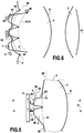
- the lighting module comprises a plurality of primary light sources, arranged in two distinct series superimposed in a first direction, here vertically one above the other, a series of first primary light sources 1 (visible in particular on the figure 2 ) being here arranged under a series of second primary light sources 2.
- the module further comprises a primary optical element 3 and a secondary projection optical element 4, having an optical axis A 1 .
- the front and rear of the module are defined by the direction of the arrow representative of the longitudinal direction of the trihedron L, V, T of the figure 1 .
- the first and second primary light sources 1 and 2 are, in the particular example described here, light-emitting diodes, or LEDs. However, the light-emitting diodes could be replaced by other light sources, without departing from the context of the invention. These primary light sources 1 and 2 are carried by the same support 5 (visible on the figure 5 ), which makes it possible to limit the number of parts of the light module.
- the primary optical element 3 comprises a correcting part 6 and a light introduction part 7 through which the light rays emitted by the first and second primary light sources 1 and 2 enter the primary optical element to be then conducted. in the corrective part.
- the light introduction part 7 comprises in a stepped arrangement, that is to say one above the other in the first direction here vertical, on the one hand a plurality of first primary optical means 8, here light guides, also called waveguides or optical guides, respectively associated with the first primary light sources 1, and on the other hand a second primary optical means 9, here a single light guide forming a strip of material extending in a second direction, here transverse, continuously and arranged plumb of the first guides 8 and of which a rear face 90, opposite to the correcting part 6, is arranged opposite the second primary light sources 2.
- two types of primary optical means are connected to the same correcting part 6 transmitting light to a secondary optical element 4.
- a first type consists of a plurality of first primary optical means 8, substantially separated from each other and arranged in series in the second transverse direction, while the second type consists of a single second primary optical means 9 formed by a strip of material which extends substantially over the entire length of the series of first primary optical means 8.
- At least one of the two types of primary optical means forms with the correcting part 6 a single-piece structure.
- the term “one-piece structure” is understood to mean that the elements of the structure cannot be separated without destruction of at least one of the elements.
- the first primary optical means in series had come integral with the corrective part 6 and that the second primary optical means 9 was attached against the rear face of the corrective part and made integral with the latter, but we understands that the light introduction part 7 in its entirety (here, with the first primary optical means in series 8 and the second primary optical means in strip 9) could be integrated in order to form a single-piece structure with the corrective part 6 .
- the first and second primary optical means are arranged on either side of the optical axis of the module, and the junction between these first and second primary optical means can pass, as can be seen on the diagram. figure 5 , by this optical axis.
- the primary optical means are constituted by light guides
- these primary optical means may be constituted, in particular in the part making it possible to generate a code beam, by microlenses, pads or collimators.
- collimators of revolution or else horizontal collimators that is to say collimators having horizontally a collimator profile which has been extruded along a vertical curve.
- the term “light guide” will denote any primary optical means.
- the corrective part 6 is a portion of a sphere, or a portion of a ball, centered on the outlet of one of the first guides. More precisely, in the particular example of figure 1 , the corrective part 6 is a half-ball, the center of which is located in the exit plane of this first guide and on the optical axis A 1 . As a variant, the exit plane of this first guide could be substantially offset from the center of the sphere by a distance less than or equal to 10% of the value of the radius of the sphere, preferably along the optical axis. .
- the front surface of the corrective part 6, in particular in the form of a spherical dome or spherical portion, constitutes a front output face 61 facing the secondary optical element 4.
- the rear face 60 of the corrective part 6 extends here in the sectional plane of the hemisphere. It could, however, have any form whatsoever, subject to ensuring the connection with the outputs of the first light guides 8 and the output of the strip of material forming the second light guide 9 and not modifying the trajectory of the rays coming from the rays. output ends of the guides and propagating in the corrective part 6.
- the projection system formed by the corrective part 6 and its exit face 61 and by the secondary optical projection element 4 defines an object focal surface SF, visible in particular on the figures 5 and 6 .
- the shape of the rear face 60 of the correcting part can be defined so that the exit surface of a first type of guides is disposed substantially on the object focal surface of the system. projection formed by the corrective part 6 and by the secondary optical element 4 and so that the exit surface of the second type of guide is offset longitudinally, that is to say axially along the optical axis, with respect to the focal object surface.
- the correcting part 6 has the shape of a half-ball or half-sphere defined by the rear face 60 forming the section plane and by the substantially spherical outlet face 61.
- Other embodiments are conceivable.
- the correcting part may be a portion of a truncated ball, that is to say cut on each side of the spherical portion formed on the exit face.
- the correcting part 6 may have the shape of a slightly deformed half-ball, in particular with portions of the ball which extend according to a progressive radius of curvature until reaching the rear face 60 of the correcting part 6.
- the light introduction part 7 and the corrective part 6 are made of the same material and have the same refractive index.
- the term “same refractive index” is understood to mean that the refractive index of the light introduction part 7 and that of the correcting part 6 are equal to the nearest hundredth.
- “same material” is meant to mean that the corrective part 6 and the part for introducing the light 7, and within the latter the first light guides 8 separated from each other and the second light guide 9 unique band-shaped, are made of the same material or are made from the same polymer. If they come from the same polymer, the first and second guides can have a different load from that of the corrective part 6.
- the guides can be made of PMMA-HT (from English Polymethyl MethAcrylate High Temperature - High Temperature polymethyl methacrylate) with a refractive index equal to 1.490 and resistant to high temperatures, and the correcting part in PMMA-8N with a refractive index equal to 1.491 and less expensive.
- PMMA-HT from English Polymethyl MethAcrylate High Temperature - High Temperature polymethyl methacrylate
- the correcting part in PMMA-8N with a refractive index equal to 1.491 and less expensive.
- the material constituting the correcting part 6 on the one hand, and the first light guides 8 and the second strip-shaped guide 9 forming the light introduction part 7 on the other hand, is transparent.
- This is a material for an optical lens, such as an organic material or possibly glass.
- Each first light guide 8 extends along a longitudinal axis and comprises at each of its longitudinal ends a rear face 80 for entering the light, arranged opposite one of the first primary light sources 1, and a front outlet, or outlet end or outlet interface, 81 playing a role of secondary light source, connected to the corrective part 6. It further comprises, to connect its two longitudinal end faces, two side faces 82, an upper face 84 and a lower face 85.
- the distance between an exit plane of the light source and the entry face of the associated first guide is between 0 , 1 millimeter and 1 millimeter.
- the first light guides 8 and the associated first primary light sources 1, and arranged opposite the entry face, are configured so that the rays emitted by these light sources enter the corresponding first guide via the rear face 80 then propagate inside this first guide towards the exit face 81, possibly by successive total internal reflections on the lower, upper and side faces.
- each first light guide 8 (that is to say transversely to the optical axis of the guide) here generally has the shape of a parallelogram, and more precisely of a rectangle.
- the cross section of the first guides could be of any shape. It could for example include curved sides. In any event, it is suitable for producing a desired shape of light beam at the output of the light module.
- the outputs 81 of the first light guides 8, here rectangular, constitute secondary light sources intended to produce respective light beams at the output of the light module. These light beams have generally rectangular shapes in cross section (that is to say transversely to the optical axis A 1 ).
- the first guides 8 are juxtaposed and form, arranged at regular intervals, a horizontal row so that secondary light sources are virtually arranged in series on the rear face of the corrective part, substantially on the focal surface object of the projection system, to be projected endlessly in this segmented arrangement.
- each of the first guides 8 is a curved surface having the overall shape of a cylindrical portion of a substantially ellipsoidal generatrix. This has the effect of concentrating the light intensity in the upper part of the beam exiting the first guide 8, which corresponds to a zone (called the “range zone”) located at the bottom of the matrix beam produced at the output of the light module and which corresponds to the cut-off zone at the junction with the beam Code produced at the output of the optical module by the interaction of the second primary light sources and of the associated second light guide 9.
- the range zone located at the bottom of the matrix beam produced at the output of the light module and which corresponds to the cut-off zone at the junction with the beam Code produced at the output of the optical module by the interaction of the second primary light sources and of the associated second light guide 9.
- the lower faces 85 of the first light guides 8 are spreading faces shaped so as to widen the cross section of these first guides, continuously, from its entry face to its exit face, each first guide. flaring down from its entrance to its exit.
- the lower faces 85 are here curved and have a flared shape. As a variant, they could be plane and inclined relative to the longitudinal axis of the first guides.
- the lower, or bottom, widening of each first guide allows vertical spreading downward of the secondary light source 81 at the exit of the first guide, which corresponds to an upward spreading of the corresponding region of the beam. Thanks to the shaping of the bottom of the first guides 8, the top of each contiguous region is softened, the light intensity decreasing vertically upwards in a progressive manner.
- the second light guide 9 is a single guide extending over substantially the entire transverse dimension of the primary optical element 3. Unlike the first light guides which consist of a plurality of guides independent of each other and providing guidance of the elements. only light rays emitted by the light source which is associated with them, the second light guide has the shape of a single continuous strip of material on one side transverse to the other of the primary optical element.
- the second light guide 9 has two vertical end faces, one of which is facing the first light guides and a rear face 90 for entering the light, arranged facing a series of second primary light sources 2. , said rear face 90 being opposite a front outlet, or outlet end or outlet interface, 91 acting as a secondary light source, connected to the corrective part 6.
- the rear face 90 of the light inlet has a transverse succession of convex shapes, here having a shape of regular boss 92, so that the rear face of the second light guide has a shape wavy.
- This wavy shape is oriented so that the center of each boss is turned away from the corrective part 6, in the direction of the approach of the light sources.
- Each boss is disposed facing one of the plurality of second primary light sources 2, these sources and the second light guide being configured and mounted facing each other so that the optical axis of a second primary light source 2 is centered on the middle of one of the bosses 92.
- the bosses are arranged in transverse series so that the end edges 93 of the bosses are contiguous two by two, and it is thus known to define a secondary input face 94 of this second primary optical means, identified as the surface connecting one after the other the end edges 93 of the bosses.
- each second primary optical means comprises a junction part 95 with the corrective part 6 and an optical profile 96 installed at a free end of the junction part, opposite to the corrective part, the junction parts of the second primary optical means forming a common junction part extending continuously in the second direction.
- the distance between an exit plane of the light source and the entry face of the associated second guide is between 0.1 millimeters and 1 millimeter.
- the second light guides 9 and the associated second primary light sources 2, and arranged opposite the bosses 92 of the entry face, are configured so that the rays emitted by these light sources enter the second guide. corresponding by the rear face 90 then propagate inside this second guide towards the exit face 91, possibly by successive total internal reflections on an upper face and a lower face 97, turned towards the first light guides 8.
- the rays emitted by a second primary light source 2 through one of the bosses 92 of the rear face 90 of the input of the rays can cross, between the secondary entry face 94 and the exit face 91, with the rays emitted by another second primary light source through another of the bosses.
- the lower face 97 of the second guide 9 is a curved surface having the overall shape of a cylindrical portion, substantially in a mirror arrangement with respect to the upper face 84 of the first guides. This has the effect of concentrating the light intensity in the lower part of the beam exiting the second guide 9, which corresponds to a zone located closest to the cut-off at the exit of the light module.
- the spacing of the opposite faces of the first and second guides also participates in the production by molding of a single part to form the primary optical element 3, by forming a clearance angle sufficient for the part to be released from the mold.
- the first light guides are ten in number and the second light guide 9 has on its input face 90 six bosses 92.
- the result is that ten first primary light sources and six second Primary light sources are arranged on the common support 5 facing the light guides.
- these numbers could vary, being however preferably strictly greater than one, and they could be equal so that as many first independent guides would be provided as there are bosses on the second single guide.
- the secondary input face 94 identified as the surface connecting the end edges of the bosses one after the other, is defocused, and the projected image of the resulting secondary light source on the focal surface SF, at the junction of the second primary optical means and of the correcting part is horizontally homogeneous due to the mixing of the rays emitted by neighboring light sources between the secondary input face 94 and the output face 91.
- the figure 3 represents the light beam 100 projected at the output of the light module.
- One can in particular distinguish light segments 110 respectively produced by the secondary light sources 81 at the output of the first guides 8, as well as the wide beam 120 formed by the second primary light sources and the associated second light guide.
- the switching on of the second primary light sources creates a Code beam and the switching on of all the primary light sources, the first as well as the second, creates a High beam, with an upper part, capable of dazzling users on the road scene, which is matrix with contiguous regions, for example segments, which can be selectively turned off to avoid this dazzling.
- the row of first light guides 8 comprises a left side end guide 8j and a right side end guide 8a, in the transverse direction.
- the left end guide is intended to produce a right light segment.
- the right end guide is intended to produce a left light segment.
- the first left end guide 8j may include a left side spreading face 82 shaped to continuously widen laterally the cross section of the guide from its entry face to its exit.
- the left side face 82 can be curved to flare from the rear inlet face 80 of the first left end guide 8j to its outlet 81. The lateral widening of the first left end guide 8j allows spreading.
- the light module shown on the figures 1 and 2 is intended to equip a left headlight of a motor vehicle, and that the figures 3 and 4 correspond to beams produced by modules in this left projector. And it is understood that the light module intended for a right headlight of a motor vehicle symmetrically comprises a first left end light guide 8a having a flared right side face similar to the left side face of the first left end guide. 8 days from the figure 2 .
- each of the first guides 8 has the effect of reducing the aperture of the light rays emitted by the primary light sources 1 and 2, the rays entering the light guides 8 and 9 being deflected by the laws of refraction . Further, at the interface between each light guide 8,9 and the correcting part 6, the light rays are not deflected due to the connection between the first guides 8 and the correcting part 6. Thanks to this, the reduced shelf opening is retained. Finally, the light rays coming out of the corrective part 6 via the exit face 61 are not or only slightly deflected thanks to the spheroidal dome shape of the exit face 61.
- the half-spherical correcting part 6 being centered on the junction at the exit of one of the first guides and of the second guide, a ray coming from the exit plane of this first guide at the level of the optical axis A 1 is normal or almost normal to the outlet face 61 and is therefore not deflected at the interface between the correcting part 6 and the surrounding air.
- a ray coming from a zone away from the optical axis is bent towards this optical axis.
- the refraction at the interface between the correcting part 6 and the surrounding medium (air) is in a way “compensated” by the spherical, or substantially spherical, shape of the outlet face 61.
- the correcting part 6 also makes it possible to correct the field aberrations of the optical system and thus ensure good quality imaging:
- the secondary optical element 4 is here a converging optical lens having the axis A 1 as its optical axis .
- the distance separating the corrective part 6 and the secondary optical element 4 is strictly greater than zero and adapted so that the plane in which the outlets of the first light guides extend substantially coincides with the object focal plane of the projection system formed by the secondary optical element 4 and by the primary optical element 3. Thanks to this, the light module is adapted to create an infinite image of the secondary light sources formed at the output ends of the guides. It is thus possible to generate several light segments, with good imaging, using the same primary optical element 3 and from light guides positioned on or outside the optical axis A 1 .
- the half-ball forming the corrective portion 6, by slightly modifying the orientation of the rays emitted by the outputs of the guides which are offset with respect to the optical axis A 1 , at the output interface 61, has a corrective effect of
- the device according to the invention makes it possible to dispense with relative positioning games between the guides associated with a Code function and a Route function, by the monobloc production of at least one series of these guides and of the corrective part associated with the all of these guides.
- this correcting part 6 is particularly advantageous to associate this correcting part 6 with an arrangement of particular light guides in that two distinct types of guides are superimposed, arranged in particular differently with respect to the focal plane which is the object of the detection system.
- the outputs of the first guides define the secondary images associated with these first guides and are positioned in the object focal surface SF of the projection system , so that the beams leaving the secondary optical projection element 4 and corresponding to the rays emitted by the first primary light sources, that is to say the sources corresponding to the upper part of the road beam, are beams parallel rays forming light segments of generally rectangular shape.
- the second primary optical means is arranged with respect to the object focal surface SF of the projection system so that the curve which bears the transverse ends of each of the patterns formed in series on the input face of the first guide is defocused, in upstream of this focal object surface.
- the light module of the invention has excellent optical efficiency.
- the luminous flux emitted by the primary light sources undergo little loss in the corrective part and they are largely recovered at the output of the module to create light beams capable of forming light segments on the one hand for the complementary road beam and an overall wide beam for the code beam.
- the light module can produce, with simple means and a corrective part common to the primary light sources, light segments for the additional road beam, the shapes of which are perfectly controlled and a Code beam made horizontally homogeneous by the defocusing of the strip of continuous material allowing the rays to be spread in the corrective part.
- Patterns of the “modulations” or “microstructures” type could be added to the surfaces of the secondary optical element 4 to deliberately add a controlled cutoff blur.
- a primary optical element carrying stepped light guides capable of being opposite series of distinct primary light sources makes it possible with a single means to achieve a plurality of optical functions, including in particular a so-called DBL function.
- DBL Dynamic Bending Light in English for mobile bending lighting
- AWL Automatic Weather Light in English, for bad weather light
- One and / or the other of these functions is easily carried out by modulating the light intensity emitted by the primary light sources opposite the light guides. For example, it is possible gradually, from right to left or from left to right depending on the direction of the turn detected, to increase the intensity of the light sources to increase the visibility on one side of the overall light beam and thus perform a function DBL. In the event of a rainy road, it is possible to reduce the light intensity of the second primary light sources which are close to the optical axis.
Landscapes
- Engineering & Computer Science (AREA)
- General Engineering & Computer Science (AREA)
- Physics & Mathematics (AREA)
- Microelectronics & Electronic Packaging (AREA)
- Optics & Photonics (AREA)
- Non-Portable Lighting Devices Or Systems Thereof (AREA)
Claims (17)
- Primäres optisches Element (3) für ein Beleuchtungsmodul eines Kraftfahrzeugs, welches einen Licht einleitenden Teil (7) umfasst, der mit mehreren primären optischen Mitteln (8, 9) versehen ist, die am Ausgang mit einem Korrekturteil (6) verbunden sind, wobei die primären optischen Mittel auf wenigstens zwei Ebenen in einer ersten Richtung in ersten (8) primären optischen Mitteln und einem zweiten (9) primären optischen Mittel, die verschieden sind, angeordnet sind, wobei mehrere erste primäre optische Mittel in Reihe in einer zweiten Richtung angeordnet sind, die im Wesentlichen senkrecht zur ersten Richtung ist,
wobei das primäre optische Element (3) dadurch gekennzeichnet ist, dass das zweite primäre optische Mittel (9) aus einem Materialstreifen besteht, der sich in der zweiten Richtung durchgehend erstreckt, oberhalb der ersten primären optischen Mittel (8). - Primäres optisches Element (3) nach Anspruch 1, dadurch gekennzeichnet, dass die primären optischen Mittel (8, 9) eine Austrittsfläche (81, 91), die mit dem Korrekturteil (6) verbunden ist, und eine Lichteintrittsfläche (80, 90), die von diesem Korrekturteil (6) abgewandt ist, aufweisen.
- Primäres optisches Element (3) nach einem der vorhergehenden Ansprüche, dadurch gekennzeichnet, dass die Eintrittsfläche (90) des zweiten primären optischen Mittels (9) mehrere konvexe Formen (92) aufweist.
- Primäres optisches Element (3) nach einem der Ansprüche 2 bis 3, dadurch gekennzeichnet, dass das zweite primäre optische Mittel (9) aus einer Reihe von zweiten primären optischen Mitteln besteht, die jeweils einen Verbindungsteil (95) mit dem Korrekturteil (6) und ein optisches Profil (96), das an einem freien Ende des Verbindungsteils angebracht ist, um die Eintrittsfläche (90) zu bilden, auf der zum Korrekturteil entgegengesetzten Seite umfassen, wobei die Verbindungsteile der zweiten primären optischen Mittel einen gemeinsamen Verbindungsteil bilden, der sich in der zweiten Richtung durchgehend erstreckt.
- Primäres optisches Element (3) nach einem der Ansprüche 2 bis 4, dadurch gekennzeichnet, dass die Austrittsflächen (81, 91) der ersten (8) primären optischen Mittel und des zweiten (9) primären optischen Mittels in der Nähe einer Objektbrennebene (SF) eines Projektionssystems positioniert sind, das wenigstens den Korrekturteil (6) umfasst.
- Primäres optisches Element (3) nach dem vorhergehenden Anspruch, dadurch gekennzeichnet, dass eine sekundäre Eintrittsfläche (94) aus einer gekrümmten Fläche besteht, die nacheinander durch jeden der Endränder (93) der konvexen Formen (92) verläuft und, bezogen auf die Ausbreitungsrichtung des Lichtes, vor der Objektbrennebene (SF) angeordnet ist.
- Primäres optisches Element (3) nach einem der vorhergehenden Ansprüche, dadurch gekennzeichnet, dass der Korrekturteil (6) eine Austrittsfläche (61) aufweist, die wenigstens teilweise die Form einer im Wesentlichen sphärischen Kuppel hat.
- Primäres optisches Element (3) nach dem vorhergehenden Anspruch, dadurch gekennzeichnet, dass die Austrittsfläche (61) von der Form einer im Wesentlichen sphärischen Kuppel im Wesentlichen zwischen den ersten primären optischen Mitteln (8) und dem zweiten primären optischen Mittel (9) zentriert ist.
- Primäres optisches Element (3) nach einem der vorhergehenden Ansprüche, dadurch gekennzeichnet, dass die ersten primären optischen Mittel (8) und der Korrekturteil (6) eine einstückige Struktur bilden.
- Primäres optisches Element (3) nach dem vorhergehenden Anspruch, dadurch gekennzeichnet, dass das zweite primäre optische Mittel (9) eine einstückige Struktur mit dem Korrekturteil (6) und den ersten primären optischen Mitteln (8) bildet.
- Primäres optisches Element (3) nach einem der vorhergehenden Ansprüche, dadurch gekennzeichnet, dass die jeweiligen Brechungsindizes der primären optischen Mittel (8, 9) und des Korrekturteils (6) im Wesentlichen identisch sind.
- Primäres optisches Element (3) nach einem der vorhergehenden Ansprüche, dadurch gekennzeichnet, dass die primären optischen Mittel (8, 9) und der Korrekturteil (6) aus demselben Material hergestellt sind.
- Optische Anordnung, welche das primäre optische Element (3) nach einem der vorhergehenden Ansprüche und mehrere primäre Lichtquellen (1, 2) umfasst, wobei jedem der ersten primären optischen Mittel (8) in der Querreihe jeweils eine erste primäre Lichtquelle zugeordnet ist, während dem zweiten primären optischen Mittel (9) wenigstens eine zweite primäre Quelle zugeordnet ist.
- Optische Anordnung nach dem vorhergehenden Anspruch in Verbindung mit wenigstens Anspruch 3 oder 4, dadurch gekennzeichnet, dass jeder der konvexen Formen (92) oder jedem der optischen Profile (96) des zweiten primären optischen Mittels (9) eine zweite primäre Quelle (9) zugeordnet ist.
- Optische Anordnung nach einem der Ansprüche 13 oder 14, wobei die primären Lichtquellen (1, 2) auf einem Träger (5) angebracht sind, der sich gegenüber sowohl den ersten primären optischen Mitteln (8) als auch dem zweiten primären optischen Mittel (9) erstreckt.
- Lichtmodul für einen Kraftfahrzeugscheinwerfer, dadurch gekennzeichnet, dass es mehrere Lichtquellen (1, 2), ein primäres optisches Element (3) nach einem der Ansprüche 1 bis 12 und ein zugeordnetes sekundäres optisches Element (4) umfasst.
- Lichtmodul nach dem vorhergehenden Anspruch, dadurch gekennzeichnet, dass die verschiedenen primären optischen Mittel des primären optischen Elements auf dem primären optischen Element derart angeordnet sind, dass die Austritte der ersten primären optischen Mittel (8) in der Nähe einer Objektbrennebene (SF) eines Projektionssystems positioniert sind, das von dem primären optischen Element und dem sekundären optischen Element gebildet wird, während der Austritt des zweiten primären optischen Mittels (9) bezüglich dieser Objektbrennebene in Längsrichtung versetzt ist.
Applications Claiming Priority (1)
| Application Number | Priority Date | Filing Date | Title |
|---|---|---|---|
| FR1559101A FR3041738B1 (fr) | 2015-09-28 | 2015-09-28 | Element optique primaire pour module lumineux de vehicule automobile |
Publications (2)
| Publication Number | Publication Date |
|---|---|
| EP3147557A1 EP3147557A1 (de) | 2017-03-29 |
| EP3147557B1 true EP3147557B1 (de) | 2020-12-09 |
Family
ID=55971057
Family Applications (1)
| Application Number | Title | Priority Date | Filing Date |
|---|---|---|---|
| EP16189922.4A Active EP3147557B1 (de) | 2015-09-28 | 2016-09-21 | Primäres optisches element für kraftfahrzeugsbeleuchtungsmodul |
Country Status (4)
| Country | Link |
|---|---|
| US (1) | US10228108B2 (de) |
| EP (1) | EP3147557B1 (de) |
| CN (1) | CN106969318B (de) |
| FR (1) | FR3041738B1 (de) |
Families Citing this family (32)
| Publication number | Priority date | Publication date | Assignee | Title |
|---|---|---|---|---|
| FR3010941B1 (fr) * | 2013-09-26 | 2017-01-13 | Valeo Vision | Dispositif et procede d'aide a la conduite |
| AT517699B1 (de) * | 2015-09-17 | 2017-04-15 | Zkw Group Gmbh | Lichtquellen-Anordnung in einem Pixellicht-Lichtmodul |
| CN107091443B (zh) * | 2016-02-18 | 2019-10-18 | 株式会社小糸制作所 | 车辆用灯具 |
| US10883689B2 (en) * | 2016-12-22 | 2021-01-05 | Honda Motor Co., Ltd. | Vehicular headlamp |
| WO2018149407A1 (zh) * | 2017-02-14 | 2018-08-23 | 亿光电子工业股份有限公司 | 导光元件、导光装置和照明模组 |
| DE102017206817A1 (de) * | 2017-04-24 | 2018-10-25 | Osram Gmbh | Beleuchtungssystem und scheinwerfer |
| FR3068435B1 (fr) * | 2017-06-29 | 2019-11-29 | Valeo Vision | Module lumineux comportant un element optique de correction de champ |
| DE102017120582A1 (de) * | 2017-09-07 | 2019-03-07 | Adolf Nissen Elektrobau Gmbh + Co. Kg | Optische Baugruppe eines Wechselverkehrszeichens und Wechselverkehrszeichen |
| FR3071040B1 (fr) * | 2017-09-12 | 2019-09-06 | Valeo Vision | Module lumineux pour l’eclairage et/ou la signalisation d’un vehicule automobile |
| FR3072446B1 (fr) * | 2017-10-13 | 2021-06-25 | Valeo Vision | "module d'eclairage formant un motif lumineux divise en une portion superieure nette et une portion inferieure floue" |
| FR3076887B1 (fr) * | 2018-01-12 | 2021-10-15 | Valeo Vision | Module optique pour vehicule automobile |
| FR3077366B1 (fr) * | 2018-01-29 | 2020-01-17 | Valeo Vision | Module lumineux comportant un element optique primaire equipe de deux nappes de mise en forme |
| JP2019175826A (ja) * | 2018-03-29 | 2019-10-10 | パナソニックIpマネジメント株式会社 | 移動体照明装置及び移動体 |
| FR3081969B1 (fr) * | 2018-06-01 | 2021-12-31 | Valeo Vision | Module lumineux pour vehicule automobile, et dispositif d'eclairage et/ou de signalisation muni d'un tel module |
| JP7176810B2 (ja) | 2018-06-21 | 2022-11-22 | スタンレー電気株式会社 | 車両用灯具 |
| FR3084724B1 (fr) * | 2018-07-31 | 2021-04-16 | Valeo Vision | Module lumineux a quatre parties de guidage |
| CN215863191U (zh) * | 2018-08-22 | 2022-02-18 | 亮锐控股有限公司 | 用于汽车照明的包括光导的光学设备 |
| FR3085463B1 (fr) * | 2018-08-31 | 2022-03-25 | Valeo Vision | Module lumineux de vehicule automobile comprenant une pluralite de guides de lumiere |
| MX2021002797A (es) | 2018-10-25 | 2021-05-12 | Hasco Vision Tech Co Ltd | Modulo de iluminacion, lampara de vehiculo y vehiculo. |
| CN210740254U (zh) | 2019-06-05 | 2020-06-12 | 华域视觉科技(上海)有限公司 | 车灯光学元件、车灯模组、车辆前照灯及车辆 |
| CN210740255U (zh) * | 2019-06-05 | 2020-06-12 | 华域视觉科技(上海)有限公司 | 一种车灯光学元件、车灯模组、车辆前照灯和车辆 |
| CN110207065B (zh) * | 2019-06-27 | 2024-06-28 | 浙江亮心汽车部件有限公司 | 一种小型导光式近光投影模组及使用该模组的灯组 |
| CN114746693B (zh) * | 2019-11-28 | 2024-09-10 | 海拉有限双合股份公司 | 用于机动车的照明设备 |
| CN212132313U (zh) | 2020-03-09 | 2020-12-11 | 华域视觉科技(上海)有限公司 | 车灯光学元件组件、车辆照明装置、车灯和车辆 |
| EP4162195A1 (de) * | 2020-06-03 | 2023-04-12 | HELLA GmbH & Co. KGaA | Scheinwerfer für ein kraftfahrzeug |
| WO2021244735A1 (en) * | 2020-06-03 | 2021-12-09 | HELLA GmbH & Co. KGaA | Headlamp for a motor vehicle |
| CN113883468A (zh) * | 2020-07-02 | 2022-01-04 | 华域视觉科技(上海)有限公司 | 一种车灯光学组件、车灯模组、车灯及车辆 |
| EP3961085A1 (de) * | 2020-08-25 | 2022-03-02 | Lumileds LLC | Beleuchtungssystem für kfz-scheinwerfer |
| US12018807B2 (en) | 2020-07-30 | 2024-06-25 | Lumileds, LLC | Automotive lighting system |
| CN112539393B (zh) * | 2020-11-16 | 2021-06-22 | 复旦大学 | 一种远光照明装置、车灯和车辆 |
| CN115707902A (zh) * | 2021-08-20 | 2023-02-21 | 华域视觉科技(上海)有限公司 | Adb远近光一体车灯照明模组及车灯 |
| FR3145594A1 (fr) * | 2023-02-02 | 2024-08-09 | Savoy Electronic Lighting | Dispositif d’eclairage avant pour vehicule terrestre |
Family Cites Families (12)
| Publication number | Priority date | Publication date | Assignee | Title |
|---|---|---|---|---|
| JP3337560B2 (ja) * | 1994-07-21 | 2002-10-21 | 株式会社デンソー | 車両用灯具装置 |
| JP2006049231A (ja) * | 2004-08-09 | 2006-02-16 | Koito Mfg Co Ltd | 車両用標識灯 |
| US7766515B2 (en) * | 2005-04-20 | 2010-08-03 | Dragonfish Technologies, Llc | Light source with non-imaging optical distribution apparatus |
| WO2007027045A1 (en) * | 2005-08-29 | 2007-03-08 | Tae-Sun Song | Light source module and optical scanning apparatus using the same |
| CN102124407A (zh) * | 2008-08-14 | 2011-07-13 | 3M创新有限公司 | 具有成像光源模块的投影系统 |
| AT508604B1 (de) * | 2009-07-31 | 2012-07-15 | Zizala Lichtsysteme Gmbh | Led-kraftfahrzeugscheinwerfer zur erzeugung einer dynamischen lichtverteilung |
| DE102010029176A1 (de) * | 2009-10-05 | 2012-12-27 | Automotive Lighting Reutlingen Gmbh | Kraftfahrzeugscheinwerfer mit einem Halbleiterlichtquellen, eine Primäroptik und eine Sekundäroptik aufweisenden Lichtmodul |
| DE102009053581B3 (de) * | 2009-10-05 | 2011-03-03 | Automotive Lighting Reutlingen Gmbh | Lichtmodul für eine Beleuchtungseinrichtung eines Kraftfahrzeugs |
| AT511499A1 (de) * | 2011-05-30 | 2012-12-15 | Zizala Lichtsysteme Gmbh | Fahrzeugscheinwerfer mit led-lichtmodulen zur erzeugung einer hauptlichtverteilung und einer zusatzlichtverteilung |
| FR2999679B1 (fr) | 2012-12-14 | 2015-01-16 | Valeo Vision | Element optique primaire, module d'eclairage et projecteur pour vehicule automobile. |
| DE102013206488A1 (de) * | 2013-04-11 | 2014-10-30 | Automotive Lighting Reutlingen Gmbh | Lichtmodul für eine Kraftfahrzeugbeleuchtungseinrichtung |
| FR3012867A1 (fr) * | 2013-11-07 | 2015-05-08 | Valeo Vision | Element optique primaire, module lumineux et projecteur pour vehicule automobile |
-
2015
- 2015-09-28 FR FR1559101A patent/FR3041738B1/fr active Active
-
2016
- 2016-09-21 EP EP16189922.4A patent/EP3147557B1/de active Active
- 2016-09-22 US US15/272,997 patent/US10228108B2/en active Active
- 2016-09-27 CN CN201610855499.3A patent/CN106969318B/zh active Active
Non-Patent Citations (1)
| Title |
|---|
| None * |
Also Published As
| Publication number | Publication date |
|---|---|
| FR3041738B1 (fr) | 2020-01-17 |
| EP3147557A1 (de) | 2017-03-29 |
| US10228108B2 (en) | 2019-03-12 |
| FR3041738A1 (fr) | 2017-03-31 |
| CN106969318A (zh) | 2017-07-21 |
| CN106969318B (zh) | 2021-10-08 |
| US20170089536A1 (en) | 2017-03-30 |
Similar Documents
| Publication | Publication Date | Title |
|---|---|---|
| EP3147557B1 (de) | Primäres optisches element für kraftfahrzeugsbeleuchtungsmodul | |
| EP2871406B1 (de) | Optisches Hauptelement, Beleuchtungsmodul und Scheinwerfer für Kraftfahrzeug | |
| EP2743567B1 (de) | Optisches hauptelement, beleuchtungsmodul und scheinwerfer für kraftfahrzeug | |
| EP3301348B1 (de) | Bandförmige beleuchtungsvorrichtung für kraftfahrzeugscheinwerfer | |
| EP3167226B1 (de) | Beleuchtungsmodul für ein kraftfahrzeug | |
| EP3067618B1 (de) | Leuchtvorrichtung mit optischen wellenleitern | |
| EP3301347B1 (de) | Beleuchtungsvorrichtung für kraftfahrzeug, die einen lichtwellenleiter umfasst | |
| WO2020025171A1 (fr) | Module lumineux imageant la surface eclairee d'un collecteur | |
| EP3002504A2 (de) | Leuchtmodul zur beleuchtung und/oder signalisierung für kraftfahrzeug | |
| EP3517827B1 (de) | Leuchtmodul, das ein primäres optisches modul umfasst, das mit zwei formgebungsmatten ausgestattet ist | |
| EP3301349B1 (de) | Optisches modul für kraftfahrzeug | |
| EP3124855A1 (de) | Beleuchtungsvorrichtung für kraftfahrzeugscheinwerfer | |
| EP3604904B1 (de) | Lichtmodul, das eine matrix von lichtquellen und ein bifokales optisches system umfasst | |
| EP2767752A1 (de) | Vorrichtung zur Beleuchtung und/oder Signalisierung mit torischer Linse | |
| EP3511608B1 (de) | Optisches modul für ein kraftfahrzeug | |
| FR3103535A1 (fr) | Module lumineux imageant un dioptre formant une surface de reflexion totale | |
| FR3038695A1 (fr) | Module lumineux pour l'eclairage et/ou la signalisation d'un vehicule automobile | |
| FR2841512A1 (fr) | Dispositif projecteur pour vehicule automobile eclairant des points de portique | |
| EP1739345A1 (de) | Optisches Modul für Kraftfahrzeug | |
| FR2898662A1 (fr) | Procede de construction d'un module de projecteur lumineux pour vehicule automobile, module et projecteur | |
| WO2023030808A1 (fr) | Module lumineux pour vehicule automobile | |
| EP3276249A1 (de) | Leuchtsystem für beleuchtungsvorrichtung und/oder signalvorrichtung für kraftfahrzeug | |
| FR3140932A1 (fr) | Module lumineux pour projecteur de véhicule automobile. | |
| FR3042846A1 (fr) | Dispositif lumineux a guides optiques |
Legal Events
| Date | Code | Title | Description |
|---|---|---|---|
| PUAI | Public reference made under article 153(3) epc to a published international application that has entered the european phase |
Free format text: ORIGINAL CODE: 0009012 |
|
| STAA | Information on the status of an ep patent application or granted ep patent |
Free format text: STATUS: THE APPLICATION HAS BEEN PUBLISHED |
|
| AK | Designated contracting states |
Kind code of ref document: A1 Designated state(s): AL AT BE BG CH CY CZ DE DK EE ES FI FR GB GR HR HU IE IS IT LI LT LU LV MC MK MT NL NO PL PT RO RS SE SI SK SM TR |
|
| AX | Request for extension of the european patent |
Extension state: BA ME |
|
| STAA | Information on the status of an ep patent application or granted ep patent |
Free format text: STATUS: REQUEST FOR EXAMINATION WAS MADE |
|
| 17P | Request for examination filed |
Effective date: 20170919 |
|
| RBV | Designated contracting states (corrected) |
Designated state(s): AL AT BE BG CH CY CZ DE DK EE ES FI FR GB GR HR HU IE IS IT LI LT LU LV MC MK MT NL NO PL PT RO RS SE SI SK SM TR |
|
| STAA | Information on the status of an ep patent application or granted ep patent |
Free format text: STATUS: EXAMINATION IS IN PROGRESS |
|
| 17Q | First examination report despatched |
Effective date: 20190524 |
|
| REG | Reference to a national code |
Ref country code: DE Ref legal event code: R079 Ref document number: 602016049334 Country of ref document: DE Free format text: PREVIOUS MAIN CLASS: F21S0008100000 Ipc: F21S0041143000 |
|
| GRAP | Despatch of communication of intention to grant a patent |
Free format text: ORIGINAL CODE: EPIDOSNIGR1 |
|
| STAA | Information on the status of an ep patent application or granted ep patent |
Free format text: STATUS: GRANT OF PATENT IS INTENDED |
|
| RIC1 | Information provided on ipc code assigned before grant |
Ipc: F21S 41/151 20180101ALI20200511BHEP Ipc: F21S 41/143 20180101AFI20200511BHEP Ipc: F21S 41/663 20180101ALI20200511BHEP Ipc: F21S 41/20 20180101ALI20200511BHEP Ipc: F21S 41/265 20180101ALI20200511BHEP |
|
| INTG | Intention to grant announced |
Effective date: 20200602 |
|
| GRAJ | Information related to disapproval of communication of intention to grant by the applicant or resumption of examination proceedings by the epo deleted |
Free format text: ORIGINAL CODE: EPIDOSDIGR1 |
|
| STAA | Information on the status of an ep patent application or granted ep patent |
Free format text: STATUS: EXAMINATION IS IN PROGRESS |
|
| GRAR | Information related to intention to grant a patent recorded |
Free format text: ORIGINAL CODE: EPIDOSNIGR71 |
|
| GRAS | Grant fee paid |
Free format text: ORIGINAL CODE: EPIDOSNIGR3 |
|
| STAA | Information on the status of an ep patent application or granted ep patent |
Free format text: STATUS: GRANT OF PATENT IS INTENDED |
|
| GRAA | (expected) grant |
Free format text: ORIGINAL CODE: 0009210 |
|
| STAA | Information on the status of an ep patent application or granted ep patent |
Free format text: STATUS: THE PATENT HAS BEEN GRANTED |
|
| INTC | Intention to grant announced (deleted) | ||
| INTG | Intention to grant announced |
Effective date: 20201028 |
|
| AK | Designated contracting states |
Kind code of ref document: B1 Designated state(s): AL AT BE BG CH CY CZ DE DK EE ES FI FR GB GR HR HU IE IS IT LI LT LU LV MC MK MT NL NO PL PT RO RS SE SI SK SM TR |
|
| REG | Reference to a national code |
Ref country code: GB Ref legal event code: FG4D Free format text: NOT ENGLISH |
|
| REG | Reference to a national code |
Ref country code: AT Ref legal event code: REF Ref document number: 1343816 Country of ref document: AT Kind code of ref document: T Effective date: 20201215 Ref country code: CH Ref legal event code: EP |
|
| REG | Reference to a national code |
Ref country code: DE Ref legal event code: R096 Ref document number: 602016049334 Country of ref document: DE |
|
| REG | Reference to a national code |
Ref country code: IE Ref legal event code: FG4D Free format text: LANGUAGE OF EP DOCUMENT: FRENCH |
|
| PG25 | Lapsed in a contracting state [announced via postgrant information from national office to epo] |
Ref country code: FI Free format text: LAPSE BECAUSE OF FAILURE TO SUBMIT A TRANSLATION OF THE DESCRIPTION OR TO PAY THE FEE WITHIN THE PRESCRIBED TIME-LIMIT Effective date: 20201209 Ref country code: GR Free format text: LAPSE BECAUSE OF FAILURE TO SUBMIT A TRANSLATION OF THE DESCRIPTION OR TO PAY THE FEE WITHIN THE PRESCRIBED TIME-LIMIT Effective date: 20210310 Ref country code: RS Free format text: LAPSE BECAUSE OF FAILURE TO SUBMIT A TRANSLATION OF THE DESCRIPTION OR TO PAY THE FEE WITHIN THE PRESCRIBED TIME-LIMIT Effective date: 20201209 Ref country code: NO Free format text: LAPSE BECAUSE OF FAILURE TO SUBMIT A TRANSLATION OF THE DESCRIPTION OR TO PAY THE FEE WITHIN THE PRESCRIBED TIME-LIMIT Effective date: 20210309 |
|
| REG | Reference to a national code |
Ref country code: AT Ref legal event code: MK05 Ref document number: 1343816 Country of ref document: AT Kind code of ref document: T Effective date: 20201209 |
|
| PG25 | Lapsed in a contracting state [announced via postgrant information from national office to epo] |
Ref country code: SE Free format text: LAPSE BECAUSE OF FAILURE TO SUBMIT A TRANSLATION OF THE DESCRIPTION OR TO PAY THE FEE WITHIN THE PRESCRIBED TIME-LIMIT Effective date: 20201209 Ref country code: LV Free format text: LAPSE BECAUSE OF FAILURE TO SUBMIT A TRANSLATION OF THE DESCRIPTION OR TO PAY THE FEE WITHIN THE PRESCRIBED TIME-LIMIT Effective date: 20201209 Ref country code: BG Free format text: LAPSE BECAUSE OF FAILURE TO SUBMIT A TRANSLATION OF THE DESCRIPTION OR TO PAY THE FEE WITHIN THE PRESCRIBED TIME-LIMIT Effective date: 20210309 |
|
| REG | Reference to a national code |
Ref country code: NL Ref legal event code: MP Effective date: 20201209 |
|
| PG25 | Lapsed in a contracting state [announced via postgrant information from national office to epo] |
Ref country code: NL Free format text: LAPSE BECAUSE OF FAILURE TO SUBMIT A TRANSLATION OF THE DESCRIPTION OR TO PAY THE FEE WITHIN THE PRESCRIBED TIME-LIMIT Effective date: 20201209 Ref country code: HR Free format text: LAPSE BECAUSE OF FAILURE TO SUBMIT A TRANSLATION OF THE DESCRIPTION OR TO PAY THE FEE WITHIN THE PRESCRIBED TIME-LIMIT Effective date: 20201209 |
|
| REG | Reference to a national code |
Ref country code: LT Ref legal event code: MG9D |
|
| PG25 | Lapsed in a contracting state [announced via postgrant information from national office to epo] |
Ref country code: LT Free format text: LAPSE BECAUSE OF FAILURE TO SUBMIT A TRANSLATION OF THE DESCRIPTION OR TO PAY THE FEE WITHIN THE PRESCRIBED TIME-LIMIT Effective date: 20201209 Ref country code: SM Free format text: LAPSE BECAUSE OF FAILURE TO SUBMIT A TRANSLATION OF THE DESCRIPTION OR TO PAY THE FEE WITHIN THE PRESCRIBED TIME-LIMIT Effective date: 20201209 Ref country code: CZ Free format text: LAPSE BECAUSE OF FAILURE TO SUBMIT A TRANSLATION OF THE DESCRIPTION OR TO PAY THE FEE WITHIN THE PRESCRIBED TIME-LIMIT Effective date: 20201209 Ref country code: EE Free format text: LAPSE BECAUSE OF FAILURE TO SUBMIT A TRANSLATION OF THE DESCRIPTION OR TO PAY THE FEE WITHIN THE PRESCRIBED TIME-LIMIT Effective date: 20201209 Ref country code: RO Free format text: LAPSE BECAUSE OF FAILURE TO SUBMIT A TRANSLATION OF THE DESCRIPTION OR TO PAY THE FEE WITHIN THE PRESCRIBED TIME-LIMIT Effective date: 20201209 Ref country code: PT Free format text: LAPSE BECAUSE OF FAILURE TO SUBMIT A TRANSLATION OF THE DESCRIPTION OR TO PAY THE FEE WITHIN THE PRESCRIBED TIME-LIMIT Effective date: 20210409 Ref country code: SK Free format text: LAPSE BECAUSE OF FAILURE TO SUBMIT A TRANSLATION OF THE DESCRIPTION OR TO PAY THE FEE WITHIN THE PRESCRIBED TIME-LIMIT Effective date: 20201209 |
|
| PG25 | Lapsed in a contracting state [announced via postgrant information from national office to epo] |
Ref country code: PL Free format text: LAPSE BECAUSE OF FAILURE TO SUBMIT A TRANSLATION OF THE DESCRIPTION OR TO PAY THE FEE WITHIN THE PRESCRIBED TIME-LIMIT Effective date: 20201209 Ref country code: AT Free format text: LAPSE BECAUSE OF FAILURE TO SUBMIT A TRANSLATION OF THE DESCRIPTION OR TO PAY THE FEE WITHIN THE PRESCRIBED TIME-LIMIT Effective date: 20201209 |
|
| REG | Reference to a national code |
Ref country code: DE Ref legal event code: R097 Ref document number: 602016049334 Country of ref document: DE |
|
| PG25 | Lapsed in a contracting state [announced via postgrant information from national office to epo] |
Ref country code: IS Free format text: LAPSE BECAUSE OF FAILURE TO SUBMIT A TRANSLATION OF THE DESCRIPTION OR TO PAY THE FEE WITHIN THE PRESCRIBED TIME-LIMIT Effective date: 20210409 |
|
| PLBE | No opposition filed within time limit |
Free format text: ORIGINAL CODE: 0009261 |
|
| STAA | Information on the status of an ep patent application or granted ep patent |
Free format text: STATUS: NO OPPOSITION FILED WITHIN TIME LIMIT |
|
| PG25 | Lapsed in a contracting state [announced via postgrant information from national office to epo] |
Ref country code: IT Free format text: LAPSE BECAUSE OF FAILURE TO SUBMIT A TRANSLATION OF THE DESCRIPTION OR TO PAY THE FEE WITHIN THE PRESCRIBED TIME-LIMIT Effective date: 20201209 Ref country code: AL Free format text: LAPSE BECAUSE OF FAILURE TO SUBMIT A TRANSLATION OF THE DESCRIPTION OR TO PAY THE FEE WITHIN THE PRESCRIBED TIME-LIMIT Effective date: 20201209 |
|
| 26N | No opposition filed |
Effective date: 20210910 |
|
| PG25 | Lapsed in a contracting state [announced via postgrant information from national office to epo] |
Ref country code: ES Free format text: LAPSE BECAUSE OF FAILURE TO SUBMIT A TRANSLATION OF THE DESCRIPTION OR TO PAY THE FEE WITHIN THE PRESCRIBED TIME-LIMIT Effective date: 20201209 Ref country code: DK Free format text: LAPSE BECAUSE OF FAILURE TO SUBMIT A TRANSLATION OF THE DESCRIPTION OR TO PAY THE FEE WITHIN THE PRESCRIBED TIME-LIMIT Effective date: 20201209 Ref country code: SI Free format text: LAPSE BECAUSE OF FAILURE TO SUBMIT A TRANSLATION OF THE DESCRIPTION OR TO PAY THE FEE WITHIN THE PRESCRIBED TIME-LIMIT Effective date: 20201209 |
|
| REG | Reference to a national code |
Ref country code: CH Ref legal event code: PL |
|
| REG | Reference to a national code |
Ref country code: BE Ref legal event code: MM Effective date: 20210930 |
|
| GBPC | Gb: european patent ceased through non-payment of renewal fee |
Effective date: 20210921 |
|
| PG25 | Lapsed in a contracting state [announced via postgrant information from national office to epo] |
Ref country code: IS Free format text: LAPSE BECAUSE OF FAILURE TO SUBMIT A TRANSLATION OF THE DESCRIPTION OR TO PAY THE FEE WITHIN THE PRESCRIBED TIME-LIMIT Effective date: 20210409 Ref country code: MC Free format text: LAPSE BECAUSE OF FAILURE TO SUBMIT A TRANSLATION OF THE DESCRIPTION OR TO PAY THE FEE WITHIN THE PRESCRIBED TIME-LIMIT Effective date: 20201209 |
|
| PG25 | Lapsed in a contracting state [announced via postgrant information from national office to epo] |
Ref country code: LU Free format text: LAPSE BECAUSE OF NON-PAYMENT OF DUE FEES Effective date: 20210921 Ref country code: IE Free format text: LAPSE BECAUSE OF NON-PAYMENT OF DUE FEES Effective date: 20210921 Ref country code: GB Free format text: LAPSE BECAUSE OF NON-PAYMENT OF DUE FEES Effective date: 20210921 Ref country code: BE Free format text: LAPSE BECAUSE OF NON-PAYMENT OF DUE FEES Effective date: 20210930 |
|
| PG25 | Lapsed in a contracting state [announced via postgrant information from national office to epo] |
Ref country code: LI Free format text: LAPSE BECAUSE OF NON-PAYMENT OF DUE FEES Effective date: 20210930 Ref country code: CH Free format text: LAPSE BECAUSE OF NON-PAYMENT OF DUE FEES Effective date: 20210930 |
|
| PG25 | Lapsed in a contracting state [announced via postgrant information from national office to epo] |
Ref country code: HU Free format text: LAPSE BECAUSE OF FAILURE TO SUBMIT A TRANSLATION OF THE DESCRIPTION OR TO PAY THE FEE WITHIN THE PRESCRIBED TIME-LIMIT; INVALID AB INITIO Effective date: 20160921 |
|
| PG25 | Lapsed in a contracting state [announced via postgrant information from national office to epo] |
Ref country code: CY Free format text: LAPSE BECAUSE OF FAILURE TO SUBMIT A TRANSLATION OF THE DESCRIPTION OR TO PAY THE FEE WITHIN THE PRESCRIBED TIME-LIMIT Effective date: 20201209 |
|
| P01 | Opt-out of the competence of the unified patent court (upc) registered |
Effective date: 20230528 |
|
| PGFP | Annual fee paid to national office [announced via postgrant information from national office to epo] |
Ref country code: FR Payment date: 20230927 Year of fee payment: 8 Ref country code: DE Payment date: 20230911 Year of fee payment: 8 |
|
| PG25 | Lapsed in a contracting state [announced via postgrant information from national office to epo] |
Ref country code: MK Free format text: LAPSE BECAUSE OF FAILURE TO SUBMIT A TRANSLATION OF THE DESCRIPTION OR TO PAY THE FEE WITHIN THE PRESCRIBED TIME-LIMIT Effective date: 20201209 |
|
| PG25 | Lapsed in a contracting state [announced via postgrant information from national office to epo] |
Ref country code: TR Free format text: LAPSE BECAUSE OF FAILURE TO SUBMIT A TRANSLATION OF THE DESCRIPTION OR TO PAY THE FEE WITHIN THE PRESCRIBED TIME-LIMIT Effective date: 20201209 |