EP3115256B1 - Kontrollverfahren eines lichtbündels, und entsprechendes beleuchtungssystem - Google Patents
Kontrollverfahren eines lichtbündels, und entsprechendes beleuchtungssystem Download PDFInfo
- Publication number
- EP3115256B1 EP3115256B1 EP16178058.0A EP16178058A EP3115256B1 EP 3115256 B1 EP3115256 B1 EP 3115256B1 EP 16178058 A EP16178058 A EP 16178058A EP 3115256 B1 EP3115256 B1 EP 3115256B1
- Authority
- EP
- European Patent Office
- Prior art keywords
- zone
- vehicle
- illumination
- light beam
- intensity
- Prior art date
- Legal status (The legal status is an assumption and is not a legal conclusion. Google has not performed a legal analysis and makes no representation as to the accuracy of the status listed.)
- Active
Links
Images

Classifications
-
- F—MECHANICAL ENGINEERING; LIGHTING; HEATING; WEAPONS; BLASTING
- F21—LIGHTING
- F21S—NON-PORTABLE LIGHTING DEVICES; SYSTEMS THEREOF; VEHICLE LIGHTING DEVICES SPECIALLY ADAPTED FOR VEHICLE EXTERIORS
- F21S41/00—Illuminating devices specially adapted for vehicle exteriors, e.g. headlamps
- F21S41/10—Illuminating devices specially adapted for vehicle exteriors, e.g. headlamps characterised by the light source
- F21S41/14—Illuminating devices specially adapted for vehicle exteriors, e.g. headlamps characterised by the light source characterised by the type of light source
- F21S41/141—Light emitting diodes [LED]
- F21S41/143—Light emitting diodes [LED] the main emission direction of the LED being parallel to the optical axis of the illuminating device
-
- B—PERFORMING OPERATIONS; TRANSPORTING
- B60—VEHICLES IN GENERAL
- B60Q—ARRANGEMENT OF SIGNALLING OR LIGHTING DEVICES, THE MOUNTING OR SUPPORTING THEREOF OR CIRCUITS THEREFOR, FOR VEHICLES IN GENERAL
- B60Q1/00—Arrangement of optical signalling or lighting devices, the mounting or supporting thereof or circuits therefor
- B60Q1/02—Arrangement of optical signalling or lighting devices, the mounting or supporting thereof or circuits therefor the devices being primarily intended to illuminate the way ahead or to illuminate other areas of way or environments
- B60Q1/04—Arrangement of optical signalling or lighting devices, the mounting or supporting thereof or circuits therefor the devices being primarily intended to illuminate the way ahead or to illuminate other areas of way or environments the devices being headlights
- B60Q1/06—Arrangement of optical signalling or lighting devices, the mounting or supporting thereof or circuits therefor the devices being primarily intended to illuminate the way ahead or to illuminate other areas of way or environments the devices being headlights adjustable, e.g. remotely-controlled from inside vehicle
- B60Q1/08—Arrangement of optical signalling or lighting devices, the mounting or supporting thereof or circuits therefor the devices being primarily intended to illuminate the way ahead or to illuminate other areas of way or environments the devices being headlights adjustable, e.g. remotely-controlled from inside vehicle automatically
- B60Q1/085—Arrangement of optical signalling or lighting devices, the mounting or supporting thereof or circuits therefor the devices being primarily intended to illuminate the way ahead or to illuminate other areas of way or environments the devices being headlights adjustable, e.g. remotely-controlled from inside vehicle automatically due to special conditions, e.g. adverse weather, type of road, badly illuminated road signs or potential dangers
-
- B—PERFORMING OPERATIONS; TRANSPORTING
- B60—VEHICLES IN GENERAL
- B60Q—ARRANGEMENT OF SIGNALLING OR LIGHTING DEVICES, THE MOUNTING OR SUPPORTING THEREOF OR CIRCUITS THEREFOR, FOR VEHICLES IN GENERAL
- B60Q1/00—Arrangement of optical signalling or lighting devices, the mounting or supporting thereof or circuits therefor
- B60Q1/02—Arrangement of optical signalling or lighting devices, the mounting or supporting thereof or circuits therefor the devices being primarily intended to illuminate the way ahead or to illuminate other areas of way or environments
- B60Q1/04—Arrangement of optical signalling or lighting devices, the mounting or supporting thereof or circuits therefor the devices being primarily intended to illuminate the way ahead or to illuminate other areas of way or environments the devices being headlights
- B60Q1/06—Arrangement of optical signalling or lighting devices, the mounting or supporting thereof or circuits therefor the devices being primarily intended to illuminate the way ahead or to illuminate other areas of way or environments the devices being headlights adjustable, e.g. remotely-controlled from inside vehicle
- B60Q1/08—Arrangement of optical signalling or lighting devices, the mounting or supporting thereof or circuits therefor the devices being primarily intended to illuminate the way ahead or to illuminate other areas of way or environments the devices being headlights adjustable, e.g. remotely-controlled from inside vehicle automatically
- B60Q1/12—Arrangement of optical signalling or lighting devices, the mounting or supporting thereof or circuits therefor the devices being primarily intended to illuminate the way ahead or to illuminate other areas of way or environments the devices being headlights adjustable, e.g. remotely-controlled from inside vehicle automatically due to steering position
-
- B—PERFORMING OPERATIONS; TRANSPORTING
- B60—VEHICLES IN GENERAL
- B60Q—ARRANGEMENT OF SIGNALLING OR LIGHTING DEVICES, THE MOUNTING OR SUPPORTING THEREOF OR CIRCUITS THEREFOR, FOR VEHICLES IN GENERAL
- B60Q1/00—Arrangement of optical signalling or lighting devices, the mounting or supporting thereof or circuits therefor
- B60Q1/02—Arrangement of optical signalling or lighting devices, the mounting or supporting thereof or circuits therefor the devices being primarily intended to illuminate the way ahead or to illuminate other areas of way or environments
- B60Q1/04—Arrangement of optical signalling or lighting devices, the mounting or supporting thereof or circuits therefor the devices being primarily intended to illuminate the way ahead or to illuminate other areas of way or environments the devices being headlights
- B60Q1/14—Arrangement of optical signalling or lighting devices, the mounting or supporting thereof or circuits therefor the devices being primarily intended to illuminate the way ahead or to illuminate other areas of way or environments the devices being headlights having dimming means
- B60Q1/1415—Dimming circuits
- B60Q1/1423—Automatic dimming circuits, i.e. switching between high beam and low beam due to change of ambient light or light level in road traffic
- B60Q1/143—Automatic dimming circuits, i.e. switching between high beam and low beam due to change of ambient light or light level in road traffic combined with another condition, e.g. using vehicle recognition from camera images or activation of wipers
-
- F—MECHANICAL ENGINEERING; LIGHTING; HEATING; WEAPONS; BLASTING
- F21—LIGHTING
- F21S—NON-PORTABLE LIGHTING DEVICES; SYSTEMS THEREOF; VEHICLE LIGHTING DEVICES SPECIALLY ADAPTED FOR VEHICLE EXTERIORS
- F21S41/00—Illuminating devices specially adapted for vehicle exteriors, e.g. headlamps
- F21S41/10—Illuminating devices specially adapted for vehicle exteriors, e.g. headlamps characterised by the light source
- F21S41/14—Illuminating devices specially adapted for vehicle exteriors, e.g. headlamps characterised by the light source characterised by the type of light source
- F21S41/141—Light emitting diodes [LED]
- F21S41/151—Light emitting diodes [LED] arranged in one or more lines
- F21S41/153—Light emitting diodes [LED] arranged in one or more lines arranged in a matrix
-
- F—MECHANICAL ENGINEERING; LIGHTING; HEATING; WEAPONS; BLASTING
- F21—LIGHTING
- F21S—NON-PORTABLE LIGHTING DEVICES; SYSTEMS THEREOF; VEHICLE LIGHTING DEVICES SPECIALLY ADAPTED FOR VEHICLE EXTERIORS
- F21S41/00—Illuminating devices specially adapted for vehicle exteriors, e.g. headlamps
- F21S41/10—Illuminating devices specially adapted for vehicle exteriors, e.g. headlamps characterised by the light source
- F21S41/14—Illuminating devices specially adapted for vehicle exteriors, e.g. headlamps characterised by the light source characterised by the type of light source
- F21S41/16—Laser light sources
-
- F—MECHANICAL ENGINEERING; LIGHTING; HEATING; WEAPONS; BLASTING
- F21—LIGHTING
- F21S—NON-PORTABLE LIGHTING DEVICES; SYSTEMS THEREOF; VEHICLE LIGHTING DEVICES SPECIALLY ADAPTED FOR VEHICLE EXTERIORS
- F21S41/00—Illuminating devices specially adapted for vehicle exteriors, e.g. headlamps
- F21S41/20—Illuminating devices specially adapted for vehicle exteriors, e.g. headlamps characterised by refractors, transparent cover plates, light guides or filters
- F21S41/25—Projection lenses
-
- F—MECHANICAL ENGINEERING; LIGHTING; HEATING; WEAPONS; BLASTING
- F21—LIGHTING
- F21S—NON-PORTABLE LIGHTING DEVICES; SYSTEMS THEREOF; VEHICLE LIGHTING DEVICES SPECIALLY ADAPTED FOR VEHICLE EXTERIORS
- F21S41/00—Illuminating devices specially adapted for vehicle exteriors, e.g. headlamps
- F21S41/30—Illuminating devices specially adapted for vehicle exteriors, e.g. headlamps characterised by reflectors
- F21S41/32—Optical layout thereof
- F21S41/36—Combinations of two or more separate reflectors
- F21S41/365—Combinations of two or more separate reflectors successively reflecting the light
-
- F—MECHANICAL ENGINEERING; LIGHTING; HEATING; WEAPONS; BLASTING
- F21—LIGHTING
- F21S—NON-PORTABLE LIGHTING DEVICES; SYSTEMS THEREOF; VEHICLE LIGHTING DEVICES SPECIALLY ADAPTED FOR VEHICLE EXTERIORS
- F21S41/00—Illuminating devices specially adapted for vehicle exteriors, e.g. headlamps
- F21S41/60—Illuminating devices specially adapted for vehicle exteriors, e.g. headlamps characterised by a variable light distribution
- F21S41/67—Illuminating devices specially adapted for vehicle exteriors, e.g. headlamps characterised by a variable light distribution by acting on reflectors
- F21S41/675—Illuminating devices specially adapted for vehicle exteriors, e.g. headlamps characterised by a variable light distribution by acting on reflectors by moving reflectors
-
- F—MECHANICAL ENGINEERING; LIGHTING; HEATING; WEAPONS; BLASTING
- F21—LIGHTING
- F21V—FUNCTIONAL FEATURES OR DETAILS OF LIGHTING DEVICES OR SYSTEMS THEREOF; STRUCTURAL COMBINATIONS OF LIGHTING DEVICES WITH OTHER ARTICLES, NOT OTHERWISE PROVIDED FOR
- F21V23/00—Arrangement of electric circuit elements in or on lighting devices
- F21V23/003—Arrangement of electric circuit elements in or on lighting devices the elements being electronics drivers or controllers for operating the light source, e.g. for a LED array
-
- H—ELECTRICITY
- H05—ELECTRIC TECHNIQUES NOT OTHERWISE PROVIDED FOR
- H05B—ELECTRIC HEATING; ELECTRIC LIGHT SOURCES NOT OTHERWISE PROVIDED FOR; CIRCUIT ARRANGEMENTS FOR ELECTRIC LIGHT SOURCES, IN GENERAL
- H05B45/00—Circuit arrangements for operating light-emitting diodes [LED]
- H05B45/10—Controlling the intensity of the light
-
- H—ELECTRICITY
- H05—ELECTRIC TECHNIQUES NOT OTHERWISE PROVIDED FOR
- H05B—ELECTRIC HEATING; ELECTRIC LIGHT SOURCES NOT OTHERWISE PROVIDED FOR; CIRCUIT ARRANGEMENTS FOR ELECTRIC LIGHT SOURCES, IN GENERAL
- H05B47/00—Circuit arrangements for operating light sources in general, i.e. where the type of light source is not relevant
- H05B47/10—Controlling the light source
- H05B47/105—Controlling the light source in response to determined parameters
- H05B47/115—Controlling the light source in response to determined parameters by determining the presence or movement of objects or living beings
-
- B—PERFORMING OPERATIONS; TRANSPORTING
- B60—VEHICLES IN GENERAL
- B60Q—ARRANGEMENT OF SIGNALLING OR LIGHTING DEVICES, THE MOUNTING OR SUPPORTING THEREOF OR CIRCUITS THEREFOR, FOR VEHICLES IN GENERAL
- B60Q2300/00—Indexing codes for automatically adjustable headlamps or automatically dimmable headlamps
- B60Q2300/05—Special features for controlling or switching of the light beam
- B60Q2300/056—Special anti-blinding beams, e.g. a standard beam is chopped or moved in order not to blind
-
- B—PERFORMING OPERATIONS; TRANSPORTING
- B60—VEHICLES IN GENERAL
- B60Q—ARRANGEMENT OF SIGNALLING OR LIGHTING DEVICES, THE MOUNTING OR SUPPORTING THEREOF OR CIRCUITS THEREFOR, FOR VEHICLES IN GENERAL
- B60Q2300/00—Indexing codes for automatically adjustable headlamps or automatically dimmable headlamps
- B60Q2300/10—Indexing codes relating to particular vehicle conditions
- B60Q2300/11—Linear movements of the vehicle
- B60Q2300/112—Vehicle speed
-
- B—PERFORMING OPERATIONS; TRANSPORTING
- B60—VEHICLES IN GENERAL
- B60Q—ARRANGEMENT OF SIGNALLING OR LIGHTING DEVICES, THE MOUNTING OR SUPPORTING THEREOF OR CIRCUITS THEREFOR, FOR VEHICLES IN GENERAL
- B60Q2300/00—Indexing codes for automatically adjustable headlamps or automatically dimmable headlamps
- B60Q2300/10—Indexing codes relating to particular vehicle conditions
- B60Q2300/12—Steering parameters
- B60Q2300/122—Steering angle
-
- B—PERFORMING OPERATIONS; TRANSPORTING
- B60—VEHICLES IN GENERAL
- B60Q—ARRANGEMENT OF SIGNALLING OR LIGHTING DEVICES, THE MOUNTING OR SUPPORTING THEREOF OR CIRCUITS THEREFOR, FOR VEHICLES IN GENERAL
- B60Q2300/00—Indexing codes for automatically adjustable headlamps or automatically dimmable headlamps
- B60Q2300/40—Indexing codes relating to other road users or special conditions
- B60Q2300/41—Indexing codes relating to other road users or special conditions preceding vehicle
-
- B—PERFORMING OPERATIONS; TRANSPORTING
- B60—VEHICLES IN GENERAL
- B60Q—ARRANGEMENT OF SIGNALLING OR LIGHTING DEVICES, THE MOUNTING OR SUPPORTING THEREOF OR CIRCUITS THEREFOR, FOR VEHICLES IN GENERAL
- B60Q2300/00—Indexing codes for automatically adjustable headlamps or automatically dimmable headlamps
- B60Q2300/40—Indexing codes relating to other road users or special conditions
- B60Q2300/42—Indexing codes relating to other road users or special conditions oncoming vehicle
-
- F—MECHANICAL ENGINEERING; LIGHTING; HEATING; WEAPONS; BLASTING
- F21—LIGHTING
- F21W—INDEXING SCHEME ASSOCIATED WITH SUBCLASSES F21K, F21L, F21S and F21V, RELATING TO USES OR APPLICATIONS OF LIGHTING DEVICES OR SYSTEMS
- F21W2102/00—Exterior vehicle lighting devices for illuminating purposes
-
- F—MECHANICAL ENGINEERING; LIGHTING; HEATING; WEAPONS; BLASTING
- F21—LIGHTING
- F21W—INDEXING SCHEME ASSOCIATED WITH SUBCLASSES F21K, F21L, F21S and F21V, RELATING TO USES OR APPLICATIONS OF LIGHTING DEVICES OR SYSTEMS
- F21W2107/00—Use or application of lighting devices on or in particular types of vehicles
- F21W2107/10—Use or application of lighting devices on or in particular types of vehicles for land vehicles
-
- F—MECHANICAL ENGINEERING; LIGHTING; HEATING; WEAPONS; BLASTING
- F21—LIGHTING
- F21Y—INDEXING SCHEME ASSOCIATED WITH SUBCLASSES F21K, F21L, F21S and F21V, RELATING TO THE FORM OR THE KIND OF THE LIGHT SOURCES OR OF THE COLOUR OF THE LIGHT EMITTED
- F21Y2115/00—Light-generating elements of semiconductor light sources
- F21Y2115/10—Light-emitting diodes [LED]
-
- Y—GENERAL TAGGING OF NEW TECHNOLOGICAL DEVELOPMENTS; GENERAL TAGGING OF CROSS-SECTIONAL TECHNOLOGIES SPANNING OVER SEVERAL SECTIONS OF THE IPC; TECHNICAL SUBJECTS COVERED BY FORMER USPC CROSS-REFERENCE ART COLLECTIONS [XRACs] AND DIGESTS
- Y02—TECHNOLOGIES OR APPLICATIONS FOR MITIGATION OR ADAPTATION AGAINST CLIMATE CHANGE
- Y02B—CLIMATE CHANGE MITIGATION TECHNOLOGIES RELATED TO BUILDINGS, e.g. HOUSING, HOUSE APPLIANCES OR RELATED END-USER APPLICATIONS
- Y02B20/00—Energy efficient lighting technologies, e.g. halogen lamps or gas discharge lamps
- Y02B20/40—Control techniques providing energy savings, e.g. smart controller or presence detection
Definitions
- the invention relates to the field of lighting and/or signaling, in particular for motor vehicles. More particularly, the invention relates to a method for controlling an overall light beam emitted by a motor vehicle headlight and obtained by the addition of intermediate beams produced by at least two lighting means, as well as to the light modules which can allow the implementation of such control methods.
- a motor vehicle is equipped with headlamps, or headlights, designed to illuminate the road ahead of the vehicle at night or in low light conditions.
- headlamps can generally be used in two lighting modes: a first "high beam” mode and a second “low beam” mode.
- the “high beam” mode allows the road to be brightly illuminated far ahead of the vehicle.
- the “low beam” mode provides more limited illumination of the road, but still offers good visibility, without dazzling other road users.
- These two lighting modes are complementary.
- the driver of the vehicle must manually change the mode depending on the circumstances, at the risk of inadvertently dazzling another road user. In practice, changing lighting modes manually can be unreliable and sometimes dangerous.
- the low beam mode sometimes provides unsatisfactory visibility for the driver of the vehicle.
- an adaptive lighting function (known in particular by the English acronym AFS for "Adaptative Frontlighting System”) have been proposed.
- AFS Adaptative Frontlighting System
- Such an adaptive lighting function is intended to automatically detect, for example by processing an image acquired by an on-board camera, a road user likely to be dazzled by a lighting beam emitted in high beam mode by a headlight, and to modify the contour of this lighting beam so as to create a shadow zone at the location where the detected user is located.
- the advantages of such an adaptive lighting function are multiple: comfort of use, better visibility compared to low beam mode, better reliability when changing modes, significantly reduced risk of glare, safer driving.
- the document EP2280215 describes an example of a lighting system for a motor vehicle headlight, equipped with an adaptive lighting function.
- the system comprises four primary optical elements, in each of which three light sources are associated with three respective light guides, as well as four secondary optical projection elements, in this case lenses, respectively associated with the four primary optical elements.
- the light emitted by each light source enters the associated light guide and exits through a rectangular exit end of the guide.
- the arrangement of the primary optical elements and their associated secondary optical element means that the light emitted by each optical guide exit end is projected by the secondary optical element so as to form a vertical light segment at the front of the vehicle.
- the light segments produced partially overlap in the horizontal direction.
- the actuation of the light sources is then varied, and they can be switched on independently of each other, selectively, to obtain the desired lighting and produce a complementary main beam, which is not dazzling for other road users.
- the beam is thus divided into a plurality of light segments that can be activated or deactivated.
- the adaptive lighting beam that can thus be achieved solely by electronic control of the ignition of the light sources, and without mechanical movement of an additional cover part, is notably known as a matrix beam.
- the documents US2006023461 A1 , WO2015022115 A1 And KR20140080156 A disclose other known lighting methods and systems.
- DBL Dynamic Bending Light
- the invention aims to propose a method for controlling light beams which manages both the creation of a matrix beam and the creation of a directional beam and which can manage the transition from one to the other.
- the invention relates to a method for controlling, according to claim 1, a global light beam emitted by a motor vehicle headlight and formed of beam portions that can be selectively activated and produced independently of each other by lighting means carried by said headlight, all of the portions forming a global light beam when they are all activated and arranged successively side by side.
- provision is made to compare the instantaneous speed of the vehicle with a first predetermined speed threshold, and to determine a zone of high lighting intensity to be produced when the instantaneous speed is greater than the first predetermined speed threshold.
- the overall light beam according to the invention forms a complementary main beam, segmented by the presence of beam portions, and intended to be associated with a dipped beam, for example by being juxtaposed or superimposed on the dipped beam to form a main beam.
- the successive arrangement side by side of the bundle portions generates or not a partial overlap of two successive portions. It will thus be possible to have an arrangement in which the bundle portions are juxtaposed, edge to edge, so as to be joined two by two, and it will be possible to have an arrangement in which the bundle portions are juxtaposed and partially superimposed so as to allow a partial overlap of one portion by another portion.
- said lighting means produce the beam portions suitable for ensuring the illumination of said high-intensity lighting zone, and a movement of said lighting means identified in the previous step is controlled, and a movement of the lighting means adjacent to the lighting means identified in the previous step, so as to create a first specific overall light beam comprising said high lighting intensity zone.
- the lighting means are moved so as to cause at least partial superposition of the beam portions produced by these identified lighting means, in the high lighting intensity zone.
- a target beam portion produced by a target lighting means, as a high lighting intensity zone to be produced and that it is possible to subsequently control two lighting means producing neighboring beam portions arranged on either side of the target beam portion so as to cause superposition of these neighboring beam portions and the target beam portion.
- the instantaneous speed of the vehicle is compared to at least one second predetermined speed threshold, of a greater value than the value of said first speed threshold, and, when the instantaneous speed is greater than said second speed threshold, the light intensity of said high-intensity lighting zone is increased by superimposing other beam portions and by concentrating the overall light beam; regardless of the first or second threshold beyond which the speed of the vehicle is detected, the direction of travel of the vehicle is detected, and, when a straight-line driving situation is detected, said high-intensity lighting zone is arranged, by superimposing beam portions, substantially in the center of the overall light beam.
- the detection is carried out, on a road scene in the vicinity of the vehicle, of a specific situation in which a third-party vehicle is likely to be dazzled by said overall light beam.
- a first target zone is determined in said overall beam including said third-party vehicle, and then lighting means carried by said projector are identified which produce the beam portions ensuring the lighting of said first target zone.
- a movement of said lighting means identified in the previous step is then controlled, so as to create a zone of lesser illumination corresponding to said first target zone, said zone of high lighting intensity then being split into two sub-zones arranged on either side of said zone of lesser illumination.
- a second target zone is determined in said overall beam as a function of the characteristics of the bend, and then lighting means carried by said projector are identified which produce the beam portions ensuring the lighting of said second target zone.
- a movement of said lighting means identified in the previous step is then controlled, so as to create a second zone of high lighting intensity corresponding to said second target zone.
- the lighting means are controlled, when it is detected that said specific situation is over, to respectively take up a position capable of creating said first specific global light beam.
- the invention also relates to an automotive lighting system according to claim 7 comprising a left headlight and a right headlight, each comprising at least one light module for implementing the control method as just presented, and which notably comprises at least one light source and movably mounted optical deflection means.
- the invention may also relate to an automotive lighting system comprising at least one light module as presented previously, as well as at least means for detecting the instantaneous speed of the vehicle, means for analyzing the detection information received and calculation means, comprising at least means for comparing the instantaneous speed with respect to at least one predetermined threshold, to give instructions for controlling the movement of the optical deflection means, on the basis of at least one piece of information on the speed of the vehicle.
- At least one light module as presented previously is arranged in a left headlight of the motor vehicle and at least one light module as presented previously is arranged in a right headlight of the vehicle, said modules being arranged so that the intermediate light beams that they generate add up to form an overall light beam.
- the lighting system may further comprise means for detecting a third-party vehicle on a road scene, and/or means for detecting a bend extending in front of the vehicle.
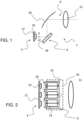
- the light module 2 comprises at least one light source 4 capable of emitting light rays in the direction of first optical deflection means 6, and an optical system 8. At the output of the module, an intermediate beam is thus produced, capable of being completed by the addition of other intermediate beams obtained by other light modules arranged nearby in the same headlight of the motor vehicle or in another headlight, so as to form an overall light beam.
- optical plane to define the vertical plane comprising the optical axis, it being observed that the optical plane corresponds to the plane of the sheet in the illustration of the Figure 1 .
- At least the first optical deflection means are controlled so that, when the instantaneous speed of the vehicle is greater than a first predetermined speed threshold, a portion of the overall light beam is concentrated to form a zone of high lighting intensity, i.e. an area illuminated more strongly than the immediately neighboring zones.
- Each light source here consists of a semiconductor source, for example a light-emitting diode, which can be associated with a printed circuit board and a radiator for cooling the electronic components carried by said board.
- the module comprises three separate light-emitting diodes 10 attached to a common printed circuit board 12.
- a vehicle lighting system may comprise a first module in which three diodes are capable of producing three beam portions and a second module in which four diodes are capable of producing four beam portions, these seven portions being juxtaposed and/or superimposed to form an overall light beam.
- the first optical deflection means 6 consist of a plurality of microelectromechanical systems (MEMS), arranged in a row matrix such that each of these microelectromechanical systems is arranged opposite a light-emitting diode (or an individually addressable "light chip” of the diode).
- MEMS microelectromechanical systems
- the microelectromechanical systems extend longitudinally in front of the light sources, and they consist of 14 movable mirrors capable of reflecting part of the light rays emitted by the light source.
- Each mirror 14 is mounted to rotate about an axis 16 carried by the module, so as to pivot between two end positions, obtained by mechanically stopping the rotation of the axis.
- a standard position of each mirror is defined as being one of the two end positions, or as the position at the center of the two end positions.
- the first standard position is calibrated so that the rays reflected by the mirror thus oriented impact the optical system arranged downstream substantially in the optical plane, and the two end positions are calibrated, either on either side of the first standard position so that the rays reflected by the mirror thus oriented impact the optical system at a distance from the optical plane corresponding to half the desired width of the light segments composing the intermediate light beam, or with one of the end positions corresponding to the standard position, and the other end position calibrated so that the rays reflected by the mirror thus oriented impact the optical system at a distance from the optical plane corresponding to the desired width of the light segments composing the intermediate light beam, in the direction of approaching the center of the overall light beam.
- the light reflected by the mirrors in one or other of the extreme positions is directed entirely towards the projection device arranged downstream in the path of the light rays.
- the optical deflection means are capable of deflecting the light rays towards a first zone of the optical system and in their second end position, the same deflection means are capable of deflecting the light rays towards a second zone of the optical system.
- the microsystems used in the invention are not binary. This means that the rotation angle can be chosen indifferently within the angular range of +/- 7°, without being limited to one or other of the extreme positions, by voltage or current control instructions depending on the type of microsystems chosen, electrostatic, piezoelectric or magnetic control for example.
- each microsystem predefined intermediate positions, which can be taken by these microsystems to form a portion of beams associated with a predefined state as will be described below.
- a primary optic is arranged between the first optical deflection means and the light source, in addition to the optical system arranged at the output of the module, to improve efficiency and avoid beam overlaps.
- This primary optic may be a collimating or focusing lens 18.
- the optical system 8 is arranged at the output of the module on the path of the light rays emitted by the light-emitting diode 10 and deflected by the mirrors 14. As illustrated, the optical system comprises a reflector 20 and a projection lens 22. It will be understood that other optical system arrangements can be implemented without departing from the context of the invention.
- the module further comprises means for controlling the light sources and electromechanical microsystems, capable of controlling on the one hand the switching on, switching off or modification of the light intensity emitted by each light source of each module, and on the other hand the rotation of the microelectromechanical systems based on vehicle traffic condition information, among which the control means receives at least one piece of information detecting the forward speed of the vehicle.
- This information can be obtained by a sensor specific to the control method according to the invention, or be taken from a vehicle information network.
- the control means include means for analyzing any information transmitted by these detection means.
- detection means may be provided on the illuminated road scene of a vehicle not to be dazzled, and/or means for detecting the presence of a bend in front of the vehicle.
- the detection means may consist, for example, of a camera facing the road scene extending in front of the vehicle, and associated image processing means, which allow the development of detection information that the detection module is capable of sending to the control means for the rotation of the microelectromechanical systems.
- the means for detecting the presence of a bend in front of the vehicle may consist of a vehicle angular speed sensor, or an on-board satellite navigation system.
- a light module 2 as just described allows the implementation of the method for controlling an overall light beam emitted by a motor vehicle headlight and obtained by the addition of intermediate beams produced by at least two lighting means according to the invention.
- light rays are emitted by the diodes 10 of the module 2 when the control module receives information relating to the automatic detection of driving conditions in high beam or information relating to a command from the driver.
- the rays are directed substantially parallel to the optical axis towards the microelectromechanical systems formed of movable mirrors 14 which are in the first standard position, and this results in an intermediate beam of the "high beam” type, divided into a number of segments equal to the number of diodes, and corresponding mirrors, provided for the entire lighting system.
- the control module Depending on the information sent by the detection means to the control module, whether it relates to the speed of the vehicle on the one hand, and to the presence of a vehicle on the road scene illuminated by the beam previously produced or to the presence of a bend in front of the vehicle on the other hand, the control module identifies which is the zone of high lighting intensity to be produced, and possibly the zone in which a detected vehicle is present, and it determines which are the diodes and the associated electromechanical microsystems to move to produce the appropriate lighting of these zones.
- the light rays deflected by a mirror represent a light segment, here vertical, of the intermediate beam and the rotation of a few degrees of a mirror generates a transverse displacement of the corresponding light segment.
- the overall light beam is obtained by the addition of two complementary intermediate light beams, in the case of a motor vehicle lighting assembly in which two light modules as just described are housed in series in a projector whose overall light beam is shown on the right of the figures, resulting from the addition of the intermediate beams of the two modules shown on the left of the figures.
- FIG. 1 illustrates a lighting sequence for which the different states of the overall light beam have been successively represented, from top to bottom, with portions 23 of light beam projected onto a vertical wall, according to the information received by the control means associated with each module, the Figure 3 illustrating in more detail the different states of the intermediate beam portions and the resulting combination to form the overall light beam, while the Figures 4 and 5 only show the overall light beam.
- the first line corresponds to a standard state with a forward speed of the vehicle lower than a first predetermined speed threshold.
- a first module comprises three diodes, and when these are lit, a first intermediate beam 24 is formed, by reflection of the light emitted on the optical deflection means in particular, consisting of three segments 2g, 0, 2d, spaced from each other, in the transverse direction, by a first determined interval d1.
- a second module comprises four diodes, and when these are lit, a second intermediate beam 26 is formed consisting of four segments 3g, 1g, 1d, 3d, spaced from each other, in the transverse direction, by a second determined interval d2.
- the modules are oriented relative to the optical axis of the vehicle, so that, by adding the two intermediate beams, an overall light beam 28 is formed composed of a succession of beam portions 23, here in the form of segments, it being understood that the segments of the first intermediate beam have a width equal to the second interval d2 to be housed between the segments of the second intermediate beam and that conversely the segments of the second intermediate beam have a width equal to the first interval d1 to be housed between the segments of the first intermediate beam.
- the segments all have the same dimension and that the intervals between the segments are the same from one intermediate beam to another.
- the width of the segments can vary from one segment to another depending on whether they are positioned in the center of the beam or on the edges.
- the central segments are thus provided to be narrower than the lateral segments.
- the intervals between segments of a subbeam may vary, and the rotation angles of the segments may differ from segment to segment.
- the segments at the edge of the beam can be provided to be fixed and to be controlled simply by switching off or switching on. This avoids having to manage a high value rotation angle for their movement, which is complicated to implement, while this movement may not be justified given the position of the segment on the road.
- the system can therefore combine moving segments and fixed segments.
- implementation modes have been shown in which advantageously all of the segments move to produce a beam without discontinuity and with high overall light intensity, without switching off one or other of the sources.
- Lines 3(b) to 3(d) of the Figure 3 illustrate the creation of a zone of high lighting intensity 30 in the center of the overall light beam, in the case where the forward speed of the vehicle V is successively greater than a first determined threshold V 1 , a second determined speed threshold V 2 and a third determined speed threshold V 3 , with V 1 ⁇ V 2 ⁇ V 3 .
- the fact that the vehicle is traveling at high speed implies that the driver must be able to anticipate possible changes in traffic conditions, and for example obstacles that may arise in his path. It is therefore advantageous to increase the light intensity in the center of the overall light beam, by moving portions of the beam and controlling the corresponding lighting means, so that the driver has a better view of what is happening in front of his vehicle, the latter traveling in a straight line.
- the zone of high lighting intensity is all the more concentrated as the speed is high.
- a first specific global light beam 31 is formed in which the high lighting intensity zone 30 is obtained by superimposing the beam portions 1g and 1d each respectively on a half of the beam portion 0. All of the microsystems, with the exception of that corresponding to the central beam portion 0, are pivoted so that the beam portions distinct from the central one approach the center by a distance equivalent to half the beam portion width.
- the first specific global light beam 31 is less wide than the global light beam 28. And more generally, it is notable that, the faster the speed, the less wide the global light beam. This is explained by the fact that the outer beam portions 3g and 3d follow the tightening of the beam portions on the center of the global beam, in order to keep a continuous global beam, and this is justified by the fact that at high speed, it is less penalizing not to see obstacles present on the sides at the height of the vehicle since the speed allows them to be overtaken on the momentum of the vehicle.
- the illumination intensity of the zone 30 is further increased by superimposing the beam portions.
- a band 32 of very high intensity is produced by superimposing the beam portions 1g, 1d and 0. At least three beam portions are superimposed to form this band 32.
- the beam portions are brought closer to the center to maintain an overall light beam without discontinuity. It can be seen that, as a result, the width of the zone of high illumination intensity, that is to say, the illumination intensity of which is greater than that of each of the portions of the overall light beam illustrated on line 3a, is greater at this stage, with V greater than V 2 , than the width of the high intensity zone when V is less than V 2 .
- FIG. 4 illustrates a state in which a turn has been detected and in which an attempt is made to create a second specific global light beam 34 comprising a second zone of high lighting intensity 36 different from the first zone of high lighting intensity 30.
- This second zone is of high lighting intensity, since the speed of the vehicle V is greater than the first threshold V 1 , and it is oriented towards the inside of the bend in order to optimize the driver's visibility of the road scene in front of the vehicle.
- the first intermediate beam 24 and the second intermediate beam experience movements, by controlling the lighting means, different from the previous case in that the central beam portion 0 is shifted towards the inside of the bend and in that that of the beam portions which is immediately adjacent to this central beam portion in the overall light beam and which is towards the inside of the face, that is to say here the portion 1d, remains unchanged.
- the target zone in which this second zone of high lighting intensity is to be brought to bear is determined by the vehicle control means according to the characteristics of the bend.
- FIG. 5 illustrates a state in which a vehicle has been detected and in which an attempt is made to create a third specific global light beam 38 in which a target zone, of lesser illumination, 40 is formed in which no potentially dazzling light ray is formed.
- the first intermediate beam 24 and the second intermediate beam 26 are modified by transverse shifting of at least one light segment, so as to create high intensity zones 30a and 30b on either side of the target zone 40.
- the width of the beam is narrowed by bringing the outer beam portions closer to the center.
- the displacement of the beam portions as a function of the speed may be horizontal or vertical.
- the horizontal displacement of a beam portion is carried out on each segment individually, and it is interesting to note that the vertical displacement is carried out on the module as a whole.
- electromechanical microsystems controllable on two perpendicular axes may be used. With such devices, the light from the area to be extinguished may be "ejected" both laterally, which is preferable for areas near the horizon, and vertically, upwards or downwards, which may be more advantageous for areas located at height.
Landscapes
- Engineering & Computer Science (AREA)
- General Engineering & Computer Science (AREA)
- Physics & Mathematics (AREA)
- Optics & Photonics (AREA)
- Microelectronics & Electronic Packaging (AREA)
- Mechanical Engineering (AREA)
- Mathematical Physics (AREA)
- Lighting Device Outwards From Vehicle And Optical Signal (AREA)
Claims (10)
- Verfahren zum Steuern eines globalen Lichtbündels (28), das von einem Kraftfahrzeugscheinwerfer emittiert wird und aus Bündelteilen (23) ausgebildet ist, die selektiv aktivierbar sind und unabhängig voneinander durch vom Scheinwerfer getragene Beleuchtungsmittel (4, 6) realisiert werden, wobei die Gesamtheit der Teile ein globales Lichtbündel ausbildet, wenn sie alle aktiviert und aufeinanderfolgend nebeneinander angeordnet sind, wobei die momentane Geschwindigkeit des Fahrzeugs mit einem vorbestimmten ersten Geschwindigkeitsschwellenwert (V1) verglichen wird, wobei ein Bereich (30) hoher Beleuchtungsintensität bestimmt wird, die realisiert werden soll, wenn die momentane Geschwindigkeit über dem vorbestimmten ersten Geschwindigkeitsschwellenwert liegt, wobei durch Erfassungsmittel identifiziert wird, welche der Beleuchtungsmittel (4, 6) die Bündelteile (23) realisieren, die dazu geeignet sind, die Beleuchtung des Bereichs (30) hoher Beleuchtungsintensität zu gewährleisten, und wobei eine Bewegung der im vorherigen Schritt identifizierten Beleuchtungsmittel und der Beleuchtungsmittel, die zu den im vorherigen Schritt identifizierten Beleuchtungsmitteln direkt benachbart sind, gesteuert wird, um ein erstes spezifisches globales Lichtbündel (31) zu erzeugen, das den Bereich hoher Beleuchtungsintensität (30) umfasst, wobei die Beleuchtungsmittel so bewegt werden, dass im Bereich hoher Beleuchtungsintensität eine zumindest teilweise Überlagerung der durch diese identifizierten Beleuchtungsmittel realisierten Bündelteile bewirkt wird, wobei die Gesamtheit der Beleuchtungsmittel (4, 6) eingeschaltet bleibt und wobei die Gesamtheit der Bündelteile (23) bewegt wird, um eine Beleuchtungskontinuität auf beiden Seiten des Bereichs (30) hoher Beleuchtungsintensität aufrechtzuerhalten, wobei eine Erfassung der Bewegungsrichtung des Fahrzeugs durchgeführt wird und wobei, wenn eine Situation des Geradeausfahrens erfasst wird, der Bereich (30) hoher Beleuchtungsintensität durch Überlagerung von Strahlenteilen im Wesentlichen in der Mitte des ersten spezifischen globalen Lichtbündels (31) angeordnet wird, wobei in einem Fahrbahnausschnitt in der Fahrzeugumgebung die Erfassung einer spezifischen Situation realisiert wird, in der ein Drittfahrzeug durch das globale Lichtbündel (28) geblendet werden kann, und ein Zielbereich im globalen Bündel bestimmt wird, der das Drittfahrzeug einschließt, dadurch gekennzeichnet, dass dann durch die Scheinwerfer getragene Beleuchtungsmittel (4, 6) identifiziert werden, die die Bündelteile realisieren, die die Beleuchtung des Zielbereichs gewährleisten, und wobei eine Bewegung der im vorherigen Schritt identifizierten Beleuchtungsmittel so gesteuert wird, dass ein dem Zielbereich entsprechender Bereich (40) geringerer Beleuchtung geschaffen wird, wobei der Bereich (30) hoher Beleuchtungsintensität dann in zwei Unterbereiche (30a, 30b) unterteilt wird, die auf beiden Seiten des Bereichs (40) geringerer Beleuchtung angeordnet sind.
- Steuerungsverfahren nach einem der vorangehenden Ansprüche, wobei die momentane Geschwindigkeit des Fahrzeugs mit mindestens einem vorbestimmten zweiten Geschwindigkeitsschwellenwert (V2) verglichen wird, dessen Wert höher als der Wert des ersten Geschwindigkeitsschwellenwerts (V1) ist, und wobei, wenn die momentane Geschwindigkeit höher als der zweite Geschwindigkeitsschwellenwert (V2) ist, die Lichtintensität des Bereichs (30) hoher Beleuchtungsintensität durch Überlagerung anderer Bündelteile und durch Konzentration des globalen Lichtbündels erhöht wird.
- Steuerungsverfahren nach einem der Ansprüche 1 oder 2, wobei in einem Fahrbahnausschnitt in der Fahrzeugumgebung die Erfassung einer spezifischen Situation realisiert wird, in der das Fahrzeug mit einer Kurve konfrontiert ist, und wobei in Abhängigkeit von den Kurvenmerkmalen ein zweiter Zielbereich im globalen Bündel bestimmt wird, wobei dann durch den Scheinwerfer getragene Beleuchtungsmittel (4, 6) identifiziert werden, die die Bündelteile realisieren, die die Beleuchtung des zweiten Zielbereichs gewährleisten, wobei eine Bewegung der im vorherigen Schritt identifizierten Beleuchtungsmittel so gesteuert wird, dass ein dem zweiten Zielbereich entsprechender zweiter Bereich (36) hoher Beleuchtungsintensität geschaffen wird.
- Steuerungsverfahren nach einem der vorangehenden Ansprüche, dadurch gekennzeichnet, dass bei der Erfassung, dass die spezifische Situation beendet ist, die Beleuchtungsmittel (4, 6) so gesteuert werden, dass sie jeweils eine Position einnehmen, die dazu geeignet ist, das erste spezifische globale Lichtbündel (31) zu erzeugen.
- Steuerungsverfahren nach einem der vorangehenden Ansprüche, dadurch gekennzeichnet, dass die Beleuchtungsmittel Lichtquellen (4) und jeweils mit mindestens einer der Lichtquellen verbundene optische Ablenkmittel (6) umfassen, wobei das Einschalten jeder Lichtquelle einzeln gesteuert wird, während die Bewegung der optischen Ablenkmittel einzeln gesteuert wird.
- Verfahren nach einem der vorangehenden Ansprüche, wobei die Bündelteile (23) aus nebeneinanderliegenden vertikalen Segmenten bestehen, wobei die Bewegung der Beleuchtungsmittel (4, 6) die Bewegung mindestens eines der Segmente und seine Überlagerung mit anderen Segmenten des globalen Lichtbündels erzeugt.
- Kraftfahrzeugbeleuchtungssystem mit einem linken Scheinwerfer und einem rechten Scheinwerfer, die jeweils mindestens ein Lichtmodul zur Durchführung des Steuerungsverfahrens nach einem der vorangehenden Ansprüche umfassen, wobei das mindestens eine Lichtmodul eine Lichtquelle (4) und beweglich montierte optische Ablenkmittel (6) umfasst.
- Kraftfahrzeugbeleuchtungssystem nach Anspruch 7, dadurch gekennzeichnet, dass es ferner ein optisches System (8) zum Emittieren eines Lichtbündels umfasst, wobei die optischen Ablenkmittel (6) zwischen der Lichtquelle und dem optischen System angeordnet sind.
- Kraftfahrzeugbeleuchtungssystem nach einem der Ansprüche 7 bis 8, dadurch gekennzeichnet, dass die optischen Ablenkmittel (6) aus elektromechanischen optischen Mikrosystemen (14, 16) bestehen, die zwischen zwei Endpositionen drehbar montiert sind.
- Kraftfahrzeugbeleuchtungssystem nach einem der Ansprüche 7 bis 9, das ferner zumindest Folgendes umfasst: Mittel zur Erfassung der momentanen Geschwindigkeit des Fahrzeugs, Mittel zur Analyse der empfangenen Erfassungsinformationen und Berechnungsmittel, die zumindest Mittel zum Vergleichen der momentanen Geschwindigkeit mit mindestens einem vorbestimmten Schwellenwert umfassen, um einen Befehl zur Bewegung der optischen Ablenkmittel (6) zu geben.
Applications Claiming Priority (1)
| Application Number | Priority Date | Filing Date | Title |
|---|---|---|---|
| FR1556627A FR3038697B1 (fr) | 2015-07-10 | 2015-07-10 | Procede de controle d’un faisceau lumineux et module d’eclairage et/ou de signalisation correspondant |
Publications (2)
| Publication Number | Publication Date |
|---|---|
| EP3115256A1 EP3115256A1 (de) | 2017-01-11 |
| EP3115256B1 true EP3115256B1 (de) | 2025-05-28 |
Family
ID=54478159
Family Applications (1)
| Application Number | Title | Priority Date | Filing Date |
|---|---|---|---|
| EP16178058.0A Active EP3115256B1 (de) | 2015-07-10 | 2016-07-05 | Kontrollverfahren eines lichtbündels, und entsprechendes beleuchtungssystem |
Country Status (5)
| Country | Link |
|---|---|
| US (1) | US9758087B2 (de) |
| EP (1) | EP3115256B1 (de) |
| JP (1) | JP6862113B2 (de) |
| CN (1) | CN106338044B (de) |
| FR (1) | FR3038697B1 (de) |
Families Citing this family (16)
| Publication number | Priority date | Publication date | Assignee | Title |
|---|---|---|---|---|
| FR3056685B1 (fr) * | 2016-09-28 | 2021-01-15 | Valeo Vision | Support monobloc pour dispositif lumineux avec matrice de micro-miroirs |
| AT519885B1 (de) * | 2017-07-03 | 2018-11-15 | Zkw Group Gmbh | Verfahren zur erzeugung einer variablen fernlicht-lichtverteilung und vorrichtung |
| EP3594059B1 (de) * | 2018-07-10 | 2022-03-09 | ZKW Group GmbH | Modular aufgebautes kraftfahrzeugscheinwerferlichtmodul |
| JP7201425B2 (ja) * | 2018-12-26 | 2023-01-10 | 株式会社小糸製作所 | 車両用灯具システム、車両用灯具の制御装置および車両用灯具の制御方法 |
| KR102663209B1 (ko) * | 2019-04-25 | 2024-05-02 | 현대자동차주식회사 | 차량의 라이다 통합 램프 장치 |
| US20200398738A1 (en) * | 2019-06-20 | 2020-12-24 | Hyundai Mobis Co., Ltd. | Headlamp for vehicle and method for controlling the same |
| CN113932189A (zh) * | 2020-06-29 | 2022-01-14 | 华域视觉科技(上海)有限公司 | 车灯光学系统、车灯模组和车辆 |
| FR3119221A1 (fr) * | 2021-01-22 | 2022-07-29 | Valeo Vision | Système d’éclairage de véhicule automobile muni d’un module lumineux apte à émettre un faisceau lumineux pixélisé |
| US11866174B2 (en) * | 2021-02-17 | 2024-01-09 | Gulfstream Aerospace Corporation | Occupant tracking lighting system |
| JP7559661B2 (ja) * | 2021-04-12 | 2024-10-02 | 市光工業株式会社 | 車両用灯具の制御装置、及び車両用灯具 |
| CN113799685B (zh) * | 2021-09-17 | 2023-04-11 | 东风汽车集团股份有限公司 | Adb大灯亮度和光区自适应调节方法及装置 |
| DE102021129680A1 (de) | 2021-11-15 | 2023-05-17 | HELLA GmbH & Co. KGaA | Verfahren zum Betreiben einer Schaltungsanordnung mit einem Steuer und/oder Regelungsmittel für ein Beleuchtungsfeld |
| US20240019099A1 (en) * | 2022-07-13 | 2024-01-18 | GM Global Technology Operations LLC | Operating and certifying an adaptive driving beam system |
| KR20240092756A (ko) * | 2022-12-15 | 2024-06-24 | 현대모비스 주식회사 | 차량용 램프 시스템 |
| US12523350B2 (en) * | 2023-11-09 | 2026-01-13 | Autosystems, a division of Magna Exteriors Inc | Digital stitching high-resolution lighting patterns for vehicle headlights |
| CN119840509B (zh) * | 2025-03-19 | 2025-06-17 | 浙江得邦车用照明有限公司 | 一种对前大灯adb分区角度自动标定的设备及其方法 |
Citations (5)
| Publication number | Priority date | Publication date | Assignee | Title |
|---|---|---|---|---|
| EP1433654A2 (de) * | 2002-12-27 | 2004-06-30 | Ichikoh Industries, Ltd. | Digitale Anzeigevorrichtung für Fahrzeuge und Verfahren zur Anzeige von Informationen |
| US20060023461A1 (en) * | 2002-01-14 | 2006-02-02 | Richard Knight | Vehicular dynamic angle adjusted lighting |
| DE102010023583A1 (de) * | 2010-06-12 | 2011-12-15 | Automotive Lighting Reutlingen Gmbh | Verfahren und Vorrichtung zum Betreiben eines Scheinwerfers für ein Fahrzeug |
| EP2548768A2 (de) * | 2011-07-22 | 2013-01-23 | Audi AG | Scheinwerfer für ein Kraftfahrzeug |
| EP2752615A1 (de) * | 2011-09-01 | 2014-07-09 | Koito Manufacturing Co., Ltd. | Automobilscheinwerfervorrichtung |
Family Cites Families (15)
| Publication number | Priority date | Publication date | Assignee | Title |
|---|---|---|---|---|
| FR2873637B1 (fr) * | 2004-07-27 | 2008-01-04 | Valeo Vision Sa | Procede d'eclairage d'une route par des projecteurs pivotants et dispositif mettant en oeuvre ce procede |
| JP4881255B2 (ja) * | 2007-08-13 | 2012-02-22 | 株式会社小糸製作所 | 車両用前照灯 |
| JP2009179113A (ja) * | 2008-01-29 | 2009-08-13 | Koito Mfg Co Ltd | 車両用前照灯装置およびその制御方法 |
| JP5132535B2 (ja) * | 2008-12-11 | 2013-01-30 | 株式会社小糸製作所 | 車両用前照灯 |
| JP5438410B2 (ja) * | 2009-07-15 | 2014-03-12 | 株式会社小糸製作所 | 車両用前照灯装置 |
| AT508604B1 (de) | 2009-07-31 | 2012-07-15 | Zizala Lichtsysteme Gmbh | Led-kraftfahrzeugscheinwerfer zur erzeugung einer dynamischen lichtverteilung |
| JP5869835B2 (ja) * | 2011-10-12 | 2016-02-24 | 株式会社小糸製作所 | 車両用前照灯制御システム |
| US9162611B2 (en) * | 2012-01-03 | 2015-10-20 | J.W. Speaker, Corporation | Solid state steerable light |
| FR2991251B1 (fr) * | 2012-06-04 | 2016-01-29 | Valeo Vision | Module d'eclairage a sources lumineuses ecartees, pour mise en oeuvre d'une fonction adb |
| JP6058344B2 (ja) * | 2012-10-12 | 2017-01-11 | 株式会社小糸製作所 | 車両用前照灯装置 |
| KR101433224B1 (ko) * | 2012-12-20 | 2014-08-25 | 에스엘 주식회사 | 차량용 램프의 복합 빔 구현 장치 및 방법 |
| DE102013216318A1 (de) * | 2013-08-16 | 2015-02-19 | Volkswagen Aktiengesellschaft | Verfahren zum Steuern einer Scheinwerferanordnung für ein Fahrzeug und Scheinwerferanordnung |
| US9187029B2 (en) * | 2013-10-01 | 2015-11-17 | Gentex Corporation | System and method for controlling exterior vehicle lights on motorways |
| JP6177105B2 (ja) * | 2013-11-20 | 2017-08-09 | 株式会社小糸製作所 | 車両用灯具の制御装置 |
| JP6201700B2 (ja) * | 2013-12-06 | 2017-09-27 | マツダ株式会社 | 車両の前照灯制御装置 |
-
2015
- 2015-07-10 FR FR1556627A patent/FR3038697B1/fr active Active
-
2016
- 2016-07-05 EP EP16178058.0A patent/EP3115256B1/de active Active
- 2016-07-08 CN CN201610537093.0A patent/CN106338044B/zh active Active
- 2016-07-08 US US15/205,428 patent/US9758087B2/en active Active
- 2016-07-08 JP JP2016136222A patent/JP6862113B2/ja active Active
Patent Citations (5)
| Publication number | Priority date | Publication date | Assignee | Title |
|---|---|---|---|---|
| US20060023461A1 (en) * | 2002-01-14 | 2006-02-02 | Richard Knight | Vehicular dynamic angle adjusted lighting |
| EP1433654A2 (de) * | 2002-12-27 | 2004-06-30 | Ichikoh Industries, Ltd. | Digitale Anzeigevorrichtung für Fahrzeuge und Verfahren zur Anzeige von Informationen |
| DE102010023583A1 (de) * | 2010-06-12 | 2011-12-15 | Automotive Lighting Reutlingen Gmbh | Verfahren und Vorrichtung zum Betreiben eines Scheinwerfers für ein Fahrzeug |
| EP2548768A2 (de) * | 2011-07-22 | 2013-01-23 | Audi AG | Scheinwerfer für ein Kraftfahrzeug |
| EP2752615A1 (de) * | 2011-09-01 | 2014-07-09 | Koito Manufacturing Co., Ltd. | Automobilscheinwerfervorrichtung |
Also Published As
| Publication number | Publication date |
|---|---|
| CN106338044B (zh) | 2021-08-20 |
| CN106338044A (zh) | 2017-01-18 |
| JP2017030735A (ja) | 2017-02-09 |
| EP3115256A1 (de) | 2017-01-11 |
| FR3038697A1 (fr) | 2017-01-13 |
| US9758087B2 (en) | 2017-09-12 |
| US20170008446A1 (en) | 2017-01-12 |
| FR3038697B1 (fr) | 2017-08-11 |
| JP6862113B2 (ja) | 2021-04-21 |
Similar Documents
| Publication | Publication Date | Title |
|---|---|---|
| EP3115256B1 (de) | Kontrollverfahren eines lichtbündels, und entsprechendes beleuchtungssystem | |
| EP2690352B1 (de) | Adaptives Beleuchtungssystem für Kraftfahrzeug | |
| EP2128521B1 (de) | Kraftfahrzeugscheinwerfer, der in der Lage ist, einen schwenkbaren Lichtstrahl abzugeben | |
| EP3002504B1 (de) | Leuchtmodul zur beleuchtung für kraftfahrzeug | |
| EP3350019B1 (de) | Beleuchtungssystem für kraftfahrzeuge | |
| EP2957464B1 (de) | Drehbares beleuchtungs- und/oder signalisierungsmodul | |
| WO2016005409A1 (fr) | Module lumineux d'un véhicule automobile | |
| EP2813395A1 (de) | Kraftfahrzeug-Scheinwerfer, der eine Laser-Lichtquelle umfasst und Verfahren zur Erzeugung eines Lichtbündel | |
| EP2546569B1 (de) | Multifunktions-Beleuchtungs-/Signalisierungsvorrichtung für Kraftfahrzeug | |
| EP2990264A2 (de) | Steuerungsverfahren eins lichtstrahls und entsprechendes beleuchtungs- und/oder signalisierungsmodul | |
| EP3511608B1 (de) | Optisches modul für ein kraftfahrzeug | |
| EP3453946A1 (de) | Leuchtmodul für kraftfahrzeug, und beleuchtungs- und/oder signalisierungsvorrichtung, die mit einem solchen modul ausgestattet ist | |
| EP3455102B1 (de) | Beleuchtungssystem und verfahren für ein kraftfahrzeug | |
| EP1870283B1 (de) | Scheinwerfereinheit mit drei Funktionen für Kraftfahrzeuge | |
| EP2853804B1 (de) | Beleuchtungs- und/oder signalisierungsmodul mit mehreren drehbaren optischen systemen | |
| EP3436307B1 (de) | Fahrzeugscheinwerfer | |
| FR3042844A1 (fr) | Systeme d'eclairage pour vehicules automobiles | |
| EP3054209B1 (de) | Beleuchtungsvorrichtung für kraftfahrzeug | |
| FR3021092A1 (fr) | Systeme d'eclairage pour projecteur de vehicule automobile comprenant plusieurs modules d'eclairage | |
| EP4472867A1 (de) | Beleuchtungssystem für ein kraftfahrzeug | |
| EP1953039A2 (de) | Multifunktionsbeleuchtungsvorrichtung für Kraftfahrzeug | |
| EP1160504A1 (de) | Verfahren um den Abblendlichtsstrahl eines Scheinwerfers an dem Gegenverkehr anzupassen, Vorrichtung, Schablone und Scheinwerfer um dieses Verfahren auszufÜhren |
Legal Events
| Date | Code | Title | Description |
|---|---|---|---|
| PUAI | Public reference made under article 153(3) epc to a published international application that has entered the european phase |
Free format text: ORIGINAL CODE: 0009012 |
|
| STAA | Information on the status of an ep patent application or granted ep patent |
Free format text: STATUS: THE APPLICATION HAS BEEN PUBLISHED |
|
| AK | Designated contracting states |
Kind code of ref document: A1 Designated state(s): AL AT BE BG CH CY CZ DE DK EE ES FI FR GB GR HR HU IE IS IT LI LT LU LV MC MK MT NL NO PL PT RO RS SE SI SK SM TR |
|
| AX | Request for extension of the european patent |
Extension state: BA ME |
|
| STAA | Information on the status of an ep patent application or granted ep patent |
Free format text: STATUS: REQUEST FOR EXAMINATION WAS MADE |
|
| 17P | Request for examination filed |
Effective date: 20170707 |
|
| RBV | Designated contracting states (corrected) |
Designated state(s): AL AT BE BG CH CY CZ DE DK EE ES FI FR GB GR HR HU IE IS IT LI LT LU LV MC MK MT NL NO PL PT RO RS SE SI SK SM TR |
|
| STAA | Information on the status of an ep patent application or granted ep patent |
Free format text: STATUS: EXAMINATION IS IN PROGRESS |
|
| 17Q | First examination report despatched |
Effective date: 20200408 |
|
| P01 | Opt-out of the competence of the unified patent court (upc) registered |
Effective date: 20230528 |
|
| GRAP | Despatch of communication of intention to grant a patent |
Free format text: ORIGINAL CODE: EPIDOSNIGR1 |
|
| STAA | Information on the status of an ep patent application or granted ep patent |
Free format text: STATUS: GRANT OF PATENT IS INTENDED |
|
| RIC1 | Information provided on ipc code assigned before grant |
Ipc: H05B 47/115 20200101ALI20241210BHEP Ipc: F21S 41/365 20180101ALI20241210BHEP Ipc: F21S 41/675 20180101ALI20241210BHEP Ipc: B60Q 1/12 20060101ALI20241210BHEP Ipc: B60Q 1/08 20060101AFI20241210BHEP |
|
| INTG | Intention to grant announced |
Effective date: 20241223 |
|
| GRAS | Grant fee paid |
Free format text: ORIGINAL CODE: EPIDOSNIGR3 |
|
| GRAA | (expected) grant |
Free format text: ORIGINAL CODE: 0009210 |
|
| STAA | Information on the status of an ep patent application or granted ep patent |
Free format text: STATUS: THE PATENT HAS BEEN GRANTED |
|
| AK | Designated contracting states |
Kind code of ref document: B1 Designated state(s): AL AT BE BG CH CY CZ DE DK EE ES FI FR GB GR HR HU IE IS IT LI LT LU LV MC MK MT NL NO PL PT RO RS SE SI SK SM TR |
|
| REG | Reference to a national code |
Ref country code: GB Ref legal event code: FG4D Free format text: NOT ENGLISH |
|
| REG | Reference to a national code |
Ref country code: CH Ref legal event code: EP |
|
| REG | Reference to a national code |
Ref country code: IE Ref legal event code: FG4D Free format text: LANGUAGE OF EP DOCUMENT: FRENCH Ref country code: DE Ref legal event code: R096 Ref document number: 602016092383 Country of ref document: DE |
|
| REG | Reference to a national code |
Ref country code: NL Ref legal event code: MP Effective date: 20250528 |
|
| PG25 | Lapsed in a contracting state [announced via postgrant information from national office to epo] |
Ref country code: ES Free format text: LAPSE BECAUSE OF FAILURE TO SUBMIT A TRANSLATION OF THE DESCRIPTION OR TO PAY THE FEE WITHIN THE PRESCRIBED TIME-LIMIT Effective date: 20250528 Ref country code: FI Free format text: LAPSE BECAUSE OF FAILURE TO SUBMIT A TRANSLATION OF THE DESCRIPTION OR TO PAY THE FEE WITHIN THE PRESCRIBED TIME-LIMIT Effective date: 20250528 |
|
| PGFP | Annual fee paid to national office [announced via postgrant information from national office to epo] |
Ref country code: DE Payment date: 20250711 Year of fee payment: 10 |
|
| REG | Reference to a national code |
Ref country code: LT Ref legal event code: MG9D |
|
| PG25 | Lapsed in a contracting state [announced via postgrant information from national office to epo] |
Ref country code: NO Free format text: LAPSE BECAUSE OF FAILURE TO SUBMIT A TRANSLATION OF THE DESCRIPTION OR TO PAY THE FEE WITHIN THE PRESCRIBED TIME-LIMIT Effective date: 20250828 Ref country code: GR Free format text: LAPSE BECAUSE OF FAILURE TO SUBMIT A TRANSLATION OF THE DESCRIPTION OR TO PAY THE FEE WITHIN THE PRESCRIBED TIME-LIMIT Effective date: 20250829 |
|
| PG25 | Lapsed in a contracting state [announced via postgrant information from national office to epo] |
Ref country code: NL Free format text: LAPSE BECAUSE OF FAILURE TO SUBMIT A TRANSLATION OF THE DESCRIPTION OR TO PAY THE FEE WITHIN THE PRESCRIBED TIME-LIMIT Effective date: 20250528 Ref country code: PL Free format text: LAPSE BECAUSE OF FAILURE TO SUBMIT A TRANSLATION OF THE DESCRIPTION OR TO PAY THE FEE WITHIN THE PRESCRIBED TIME-LIMIT Effective date: 20250528 |
|
| PG25 | Lapsed in a contracting state [announced via postgrant information from national office to epo] |
Ref country code: BG Free format text: LAPSE BECAUSE OF FAILURE TO SUBMIT A TRANSLATION OF THE DESCRIPTION OR TO PAY THE FEE WITHIN THE PRESCRIBED TIME-LIMIT Effective date: 20250528 |
|
| PG25 | Lapsed in a contracting state [announced via postgrant information from national office to epo] |
Ref country code: HR Free format text: LAPSE BECAUSE OF FAILURE TO SUBMIT A TRANSLATION OF THE DESCRIPTION OR TO PAY THE FEE WITHIN THE PRESCRIBED TIME-LIMIT Effective date: 20250528 |
|
| PGFP | Annual fee paid to national office [announced via postgrant information from national office to epo] |
Ref country code: FR Payment date: 20250730 Year of fee payment: 10 |
|
| PG25 | Lapsed in a contracting state [announced via postgrant information from national office to epo] |
Ref country code: RS Free format text: LAPSE BECAUSE OF FAILURE TO SUBMIT A TRANSLATION OF THE DESCRIPTION OR TO PAY THE FEE WITHIN THE PRESCRIBED TIME-LIMIT Effective date: 20250828 |
|
| PG25 | Lapsed in a contracting state [announced via postgrant information from national office to epo] |
Ref country code: IS Free format text: LAPSE BECAUSE OF FAILURE TO SUBMIT A TRANSLATION OF THE DESCRIPTION OR TO PAY THE FEE WITHIN THE PRESCRIBED TIME-LIMIT Effective date: 20250928 |
|
| PG25 | Lapsed in a contracting state [announced via postgrant information from national office to epo] |
Ref country code: LV Free format text: LAPSE BECAUSE OF FAILURE TO SUBMIT A TRANSLATION OF THE DESCRIPTION OR TO PAY THE FEE WITHIN THE PRESCRIBED TIME-LIMIT Effective date: 20250528 |
|
| REG | Reference to a national code |
Ref country code: AT Ref legal event code: MK05 Ref document number: 1798460 Country of ref document: AT Kind code of ref document: T Effective date: 20250528 |
|
| PG25 | Lapsed in a contracting state [announced via postgrant information from national office to epo] |
Ref country code: SM Free format text: LAPSE BECAUSE OF FAILURE TO SUBMIT A TRANSLATION OF THE DESCRIPTION OR TO PAY THE FEE WITHIN THE PRESCRIBED TIME-LIMIT Effective date: 20250528 Ref country code: AT Free format text: LAPSE BECAUSE OF FAILURE TO SUBMIT A TRANSLATION OF THE DESCRIPTION OR TO PAY THE FEE WITHIN THE PRESCRIBED TIME-LIMIT Effective date: 20250528 Ref country code: DK Free format text: LAPSE BECAUSE OF FAILURE TO SUBMIT A TRANSLATION OF THE DESCRIPTION OR TO PAY THE FEE WITHIN THE PRESCRIBED TIME-LIMIT Effective date: 20250528 |
|
| PG25 | Lapsed in a contracting state [announced via postgrant information from national office to epo] |
Ref country code: CZ Free format text: LAPSE BECAUSE OF FAILURE TO SUBMIT A TRANSLATION OF THE DESCRIPTION OR TO PAY THE FEE WITHIN THE PRESCRIBED TIME-LIMIT Effective date: 20250528 |
|
| PG25 | Lapsed in a contracting state [announced via postgrant information from national office to epo] |
Ref country code: EE Free format text: LAPSE BECAUSE OF FAILURE TO SUBMIT A TRANSLATION OF THE DESCRIPTION OR TO PAY THE FEE WITHIN THE PRESCRIBED TIME-LIMIT Effective date: 20250528 |
|
| PG25 | Lapsed in a contracting state [announced via postgrant information from national office to epo] |
Ref country code: RO Free format text: LAPSE BECAUSE OF FAILURE TO SUBMIT A TRANSLATION OF THE DESCRIPTION OR TO PAY THE FEE WITHIN THE PRESCRIBED TIME-LIMIT Effective date: 20250528 Ref country code: SK Free format text: LAPSE BECAUSE OF FAILURE TO SUBMIT A TRANSLATION OF THE DESCRIPTION OR TO PAY THE FEE WITHIN THE PRESCRIBED TIME-LIMIT Effective date: 20250528 |
|
| PG25 | Lapsed in a contracting state [announced via postgrant information from national office to epo] |
Ref country code: IT Free format text: LAPSE BECAUSE OF FAILURE TO SUBMIT A TRANSLATION OF THE DESCRIPTION OR TO PAY THE FEE WITHIN THE PRESCRIBED TIME-LIMIT Effective date: 20250528 |
|
| REG | Reference to a national code |
Ref country code: CH Ref legal event code: H13 Free format text: ST27 STATUS EVENT CODE: U-0-0-H10-H13 (AS PROVIDED BY THE NATIONAL OFFICE) Effective date: 20260224 |
|
| REG | Reference to a national code |
Ref country code: DE Ref legal event code: R097 Ref document number: 602016092383 Country of ref document: DE |
|
| PG25 | Lapsed in a contracting state [announced via postgrant information from national office to epo] |
Ref country code: LU Free format text: LAPSE BECAUSE OF NON-PAYMENT OF DUE FEES Effective date: 20250705 |
|
| REG | Reference to a national code |
Ref country code: BE Ref legal event code: MM Effective date: 20250731 |
|
| PLBE | No opposition filed within time limit |
Free format text: ORIGINAL CODE: 0009261 |
|
| STAA | Information on the status of an ep patent application or granted ep patent |
Free format text: STATUS: NO OPPOSITION FILED WITHIN TIME LIMIT |
|
| REG | Reference to a national code |
Ref country code: CH Ref legal event code: L10 Free format text: ST27 STATUS EVENT CODE: U-0-0-L10-L00 (AS PROVIDED BY THE NATIONAL OFFICE) Effective date: 20260409 |
|
| PG25 | Lapsed in a contracting state [announced via postgrant information from national office to epo] |
Ref country code: BE Free format text: LAPSE BECAUSE OF NON-PAYMENT OF DUE FEES Effective date: 20250731 |