EP3436307B1 - Fahrzeugscheinwerfer - Google Patents
Fahrzeugscheinwerfer Download PDFInfo
- Publication number
- EP3436307B1 EP3436307B1 EP17716952.1A EP17716952A EP3436307B1 EP 3436307 B1 EP3436307 B1 EP 3436307B1 EP 17716952 A EP17716952 A EP 17716952A EP 3436307 B1 EP3436307 B1 EP 3436307B1
- Authority
- EP
- European Patent Office
- Prior art keywords
- modules
- complementary
- lighting
- module
- main
- Prior art date
- Legal status (The legal status is an assumption and is not a legal conclusion. Google has not performed a legal analysis and makes no representation as to the accuracy of the status listed.)
- Active
Links
- 230000000295 complement effect Effects 0.000 claims description 52
- 238000000034 method Methods 0.000 claims description 9
- 230000004913 activation Effects 0.000 claims description 7
- 238000013459 approach Methods 0.000 claims description 5
- 238000005286 illumination Methods 0.000 claims description 5
- 230000004297 night vision Effects 0.000 claims description 5
- 238000005375 photometry Methods 0.000 description 6
- 230000004438 eyesight Effects 0.000 description 3
- 230000003068 static effect Effects 0.000 description 3
- SEQDDYPDSLOBDC-UHFFFAOYSA-N Temazepam Chemical compound N=1C(O)C(=O)N(C)C2=CC=C(Cl)C=C2C=1C1=CC=CC=C1 SEQDDYPDSLOBDC-UHFFFAOYSA-N 0.000 description 2
- 238000009826 distribution Methods 0.000 description 2
- 230000004907 flux Effects 0.000 description 2
- 230000003044 adaptive effect Effects 0.000 description 1
- 230000002411 adverse Effects 0.000 description 1
- 238000005452 bending Methods 0.000 description 1
- 230000008033 biological extinction Effects 0.000 description 1
- 238000006073 displacement reaction Methods 0.000 description 1
- 239000011521 glass Substances 0.000 description 1
- 238000004519 manufacturing process Methods 0.000 description 1
- 230000003287 optical effect Effects 0.000 description 1
- 230000008569 process Effects 0.000 description 1
- 230000000750 progressive effect Effects 0.000 description 1
- 230000009467 reduction Effects 0.000 description 1
- 239000013589 supplement Substances 0.000 description 1
- 230000007704 transition Effects 0.000 description 1
- 230000001960 triggered effect Effects 0.000 description 1
- 230000000007 visual effect Effects 0.000 description 1
- 238000004804 winding Methods 0.000 description 1
Images


Classifications
-
- B—PERFORMING OPERATIONS; TRANSPORTING
- B60—VEHICLES IN GENERAL
- B60Q—ARRANGEMENT OF SIGNALLING OR LIGHTING DEVICES, THE MOUNTING OR SUPPORTING THEREOF OR CIRCUITS THEREFOR, FOR VEHICLES IN GENERAL
- B60Q1/00—Arrangement of optical signalling or lighting devices, the mounting or supporting thereof or circuits therefor
- B60Q1/02—Arrangement of optical signalling or lighting devices, the mounting or supporting thereof or circuits therefor the devices being primarily intended to illuminate the way ahead or to illuminate other areas of way or environments
- B60Q1/04—Arrangement of optical signalling or lighting devices, the mounting or supporting thereof or circuits therefor the devices being primarily intended to illuminate the way ahead or to illuminate other areas of way or environments the devices being headlights
- B60Q1/06—Arrangement of optical signalling or lighting devices, the mounting or supporting thereof or circuits therefor the devices being primarily intended to illuminate the way ahead or to illuminate other areas of way or environments the devices being headlights adjustable, e.g. remotely-controlled from inside vehicle
- B60Q1/08—Arrangement of optical signalling or lighting devices, the mounting or supporting thereof or circuits therefor the devices being primarily intended to illuminate the way ahead or to illuminate other areas of way or environments the devices being headlights adjustable, e.g. remotely-controlled from inside vehicle automatically
- B60Q1/085—Arrangement of optical signalling or lighting devices, the mounting or supporting thereof or circuits therefor the devices being primarily intended to illuminate the way ahead or to illuminate other areas of way or environments the devices being headlights adjustable, e.g. remotely-controlled from inside vehicle automatically due to special conditions, e.g. adverse weather, type of road, badly illuminated road signs or potential dangers
-
- B—PERFORMING OPERATIONS; TRANSPORTING
- B60—VEHICLES IN GENERAL
- B60Q—ARRANGEMENT OF SIGNALLING OR LIGHTING DEVICES, THE MOUNTING OR SUPPORTING THEREOF OR CIRCUITS THEREFOR, FOR VEHICLES IN GENERAL
- B60Q1/00—Arrangement of optical signalling or lighting devices, the mounting or supporting thereof or circuits therefor
- B60Q1/02—Arrangement of optical signalling or lighting devices, the mounting or supporting thereof or circuits therefor the devices being primarily intended to illuminate the way ahead or to illuminate other areas of way or environments
- B60Q1/04—Arrangement of optical signalling or lighting devices, the mounting or supporting thereof or circuits therefor the devices being primarily intended to illuminate the way ahead or to illuminate other areas of way or environments the devices being headlights
- B60Q1/06—Arrangement of optical signalling or lighting devices, the mounting or supporting thereof or circuits therefor the devices being primarily intended to illuminate the way ahead or to illuminate other areas of way or environments the devices being headlights adjustable, e.g. remotely-controlled from inside vehicle
- B60Q1/08—Arrangement of optical signalling or lighting devices, the mounting or supporting thereof or circuits therefor the devices being primarily intended to illuminate the way ahead or to illuminate other areas of way or environments the devices being headlights adjustable, e.g. remotely-controlled from inside vehicle automatically
- B60Q1/12—Arrangement of optical signalling or lighting devices, the mounting or supporting thereof or circuits therefor the devices being primarily intended to illuminate the way ahead or to illuminate other areas of way or environments the devices being headlights adjustable, e.g. remotely-controlled from inside vehicle automatically due to steering position
-
- B—PERFORMING OPERATIONS; TRANSPORTING
- B60—VEHICLES IN GENERAL
- B60Q—ARRANGEMENT OF SIGNALLING OR LIGHTING DEVICES, THE MOUNTING OR SUPPORTING THEREOF OR CIRCUITS THEREFOR, FOR VEHICLES IN GENERAL
- B60Q1/00—Arrangement of optical signalling or lighting devices, the mounting or supporting thereof or circuits therefor
- B60Q1/02—Arrangement of optical signalling or lighting devices, the mounting or supporting thereof or circuits therefor the devices being primarily intended to illuminate the way ahead or to illuminate other areas of way or environments
- B60Q1/04—Arrangement of optical signalling or lighting devices, the mounting or supporting thereof or circuits therefor the devices being primarily intended to illuminate the way ahead or to illuminate other areas of way or environments the devices being headlights
- B60Q1/18—Arrangement of optical signalling or lighting devices, the mounting or supporting thereof or circuits therefor the devices being primarily intended to illuminate the way ahead or to illuminate other areas of way or environments the devices being headlights being additional front lights
-
- B—PERFORMING OPERATIONS; TRANSPORTING
- B60—VEHICLES IN GENERAL
- B60Q—ARRANGEMENT OF SIGNALLING OR LIGHTING DEVICES, THE MOUNTING OR SUPPORTING THEREOF OR CIRCUITS THEREFOR, FOR VEHICLES IN GENERAL
- B60Q2300/00—Indexing codes for automatically adjustable headlamps or automatically dimmable headlamps
- B60Q2300/10—Indexing codes relating to particular vehicle conditions
- B60Q2300/11—Linear movements of the vehicle
- B60Q2300/112—Vehicle speed
-
- B—PERFORMING OPERATIONS; TRANSPORTING
- B60—VEHICLES IN GENERAL
- B60Q—ARRANGEMENT OF SIGNALLING OR LIGHTING DEVICES, THE MOUNTING OR SUPPORTING THEREOF OR CIRCUITS THEREFOR, FOR VEHICLES IN GENERAL
- B60Q2300/00—Indexing codes for automatically adjustable headlamps or automatically dimmable headlamps
- B60Q2300/10—Indexing codes relating to particular vehicle conditions
- B60Q2300/12—Steering parameters
- B60Q2300/122—Steering angle
-
- B—PERFORMING OPERATIONS; TRANSPORTING
- B60—VEHICLES IN GENERAL
- B60Q—ARRANGEMENT OF SIGNALLING OR LIGHTING DEVICES, THE MOUNTING OR SUPPORTING THEREOF OR CIRCUITS THEREFOR, FOR VEHICLES IN GENERAL
- B60Q2300/00—Indexing codes for automatically adjustable headlamps or automatically dimmable headlamps
- B60Q2300/30—Indexing codes relating to the vehicle environment
- B60Q2300/31—Atmospheric conditions
- B60Q2300/312—Adverse weather
-
- B—PERFORMING OPERATIONS; TRANSPORTING
- B60—VEHICLES IN GENERAL
- B60Q—ARRANGEMENT OF SIGNALLING OR LIGHTING DEVICES, THE MOUNTING OR SUPPORTING THEREOF OR CIRCUITS THEREFOR, FOR VEHICLES IN GENERAL
- B60Q2300/00—Indexing codes for automatically adjustable headlamps or automatically dimmable headlamps
- B60Q2300/30—Indexing codes relating to the vehicle environment
- B60Q2300/33—Driving situation
- B60Q2300/331—Driving situation characterised by the driving side, e.g. on the left or right hand side
-
- B—PERFORMING OPERATIONS; TRANSPORTING
- B60—VEHICLES IN GENERAL
- B60Q—ARRANGEMENT OF SIGNALLING OR LIGHTING DEVICES, THE MOUNTING OR SUPPORTING THEREOF OR CIRCUITS THEREFOR, FOR VEHICLES IN GENERAL
- B60Q2300/00—Indexing codes for automatically adjustable headlamps or automatically dimmable headlamps
- B60Q2300/40—Indexing codes relating to other road users or special conditions
- B60Q2300/45—Special conditions, e.g. pedestrians, road signs or potential dangers
Definitions
- the present invention generally relates to a headlamp intended to be mounted on a motor vehicle.
- a lighting module emits a single type of beam so that the photometry of the projector, that is to say the illuminated area in front of the vehicle, is static whatever the traffic condition unless using an element such as a mask, a screen or even a barrel which makes the system and its manufacture more complicated.
- JP2005088856A a headlamp comprising a main module producing a low beam and three adjacent fixed complementary modules switched on successively in a bend. . This document does not make it possible to ensure modular photometry with a wide variety of lighting configurations.
- a projector comprising a main module for low beam and two complementary modules that can be oriented in azimuth.
- the two complementary modules together produce a variable complementary beam intended to complete the main beam to produce an adaptive high beam, a bend beam and a motorway beam as required.
- the elevation position of the beams of each of the complementary modules can be modified by relative displacement of the light source and of an optic inside the module.
- An object of the present invention is to respond to the drawbacks of the prior art documents mentioned above and in particular, first of all, to provide an economical vehicle headlight, simple to implement and capable of providing photometry modular and combining multiple functionalities at optimal performance levels.
- a first aspect of the invention relates to a headlamp characterized by the characterizing part of claim 1
- control unit is able to control the intensity of the lighting of the complementary modules so that the first complementary module lights up instantaneously at maximum intensity then the second then the third so as to provide a field of vision maximum night time to the driver of the vehicle during the turn.
- the unit controls the modules starting from the innermost module in the bend towards the main module, so that they gradually turn off until the exit from the bend.
- all the additional modules are switched on simultaneously at maximum power as soon as an angle of rotation of the steering wheel is detected and/or the activation of the direction indicator.
- a fourth aspect of the invention relates to a motor vehicle comprising at least one vehicle headlamp as described above.
- the figure 1 shows a vehicle headlamp 1 according to an embodiment of the present invention.
- this headlamp comprises a main module 2, 2', 2" arranged to emit a main beam of light 31, 41, 45, 51, 61, 71, preferably a 2" main beam/dipped beam 2, 2', that is to say that it is a bi-function module which can emit a beam of low beam or a beam of high beam, which comprises one or more motors (not visible) arranged to adjust it in elevation and in azimuth according to the vertical and horizontal arrows of the figure 1 .
- the main dipped beam can have a flat cut-off, i.e. its photometry (illumination zone) is essentially rectangular without an enlarged illumination zone for the side of the road or with a cut-off at X° (for example 15°) so that the main beam also illuminates the lower side of the road.
- this projector comprises a plurality of complementary modules 3, 3', 3" each arranged to emit a complementary light beam 34, 44, 54, 74; 33, 43, 53, 73; 32, 42, 52, 62, 72, different from the main beam of light 41, 45, 51, 61, 71.
- the complementary modules 3, 3', 3" comprise each preferably a motor arranged to adjust the complementary module for which it is intended in elevation and in azimuth independently of each other as represented by the vertical and horizontal arrows.
- the projector 1 also comprises an adjustment means 4, which may include the previously mentioned motors, to adjust in elevation and in azimuth each of the lighting modules 2, 2', 2", 3, 3', 3" , main and complementary, and a control unit 5 to issue an order to the adjustment means 4 to orient each of the lighting modules 2, 2', 2", 3, 3', 3" in elevation and in azimuth independently of the each other and control the light intensity of each module also independently of each other.
- an adjustment means 4 which may include the previously mentioned motors, to adjust in elevation and in azimuth each of the lighting modules 2, 2', 2", 3, 3', 3" , main and complementary
- a control unit 5 to issue an order to the adjustment means 4 to orient each of the lighting modules 2, 2', 2", 3, 3', 3" in elevation and in azimuth independently of the each other and control the light intensity of each module also independently of each other.
- the figures 2A and 2B represent a particular embodiment of the present invention in which the main lighting module 2 is arranged to emit a beam of light 31 with a flat cut-off to emit a dipped beam (or dipped beam)”.
- the beam of the main module does not illuminate an additional zone on the lower side of the road further forward than the rest of the road.
- At least one 3 of the three complementary modules 3, 3', 3" is arranged to project a symmetrical cutoff beam 34 adjacent to a front side of the flat cutoff light beam 31 so as to complement the light beam with a flat cutoff 31 to illuminate this additional zone on the low side of the road.
- the adjustment means 4 can move the symmetrical cutoff beam 34 horizontally between the lateral ends of the beam of light with flat cutoff 31 illuminating, optionally, a low side to the left or to the right of the vehicle, thus implementing a management of RtoD/RtoG (right-hand drive/left-hand drive).
- the other complementary modules 3' and 3" are arranged to respectively project beams 33, 32 adjacent to the side faces of the main beam 31.
- the beam 32 has a rectangular shape, which makes it possible to at least partially superimpose it with the main beam 2 and the beam at symmetrical cutoff 34 so as to standardize the dipped beam and is therefore preferably moved together with the cutoff beam 34.
- adjacent By adjacent is meant the position of the complementary beams following the main beams. However, a slight superimposition of the beams will make it possible to deal with the homogeneity linked to the association of these different beams.
- Such an embodiment makes it possible to provide additional lighting to that obtained by the dipped beam, taking into account the direction of driving (right direction DtoD/left direction DtoG) without the need for mechanical adjustment.
- the Figure 3A represents another embodiment of the invention in which the complementary modules 3, 3', 3" are arranged to sequentially project their beam 44, 43, 42 so as to superimpose the complementary beams sequentially with the main beam 41 of 15° dipped beam, as well as a beam also called "Spot" 45 emitted by the main 2" driving beam.
- spot is used because its ovoid shape resembles a lighting spot, the contour of which is represented by a discontinuous closed line.
- the spot forms the main beam beam 45 in cooperation with the main beam 41.
- Such an embodiment makes it possible to obtain a supplement to the main beam function.
- the Fig. 3C represents another embodiment of the invention in which at least one 3" of the complementary modules 3, 3', 3" is arranged so as to be able to emit a beam 62 which can move according to the horizontal and vertical arrows with respect to main beam 61.
- Such an embodiment makes it possible to follow a target identified, preferably, by an obstacle detector or the like, an ability also designated by the English terms “Marking Light”.
- the Figure 3B represents another embodiment of the invention in which the complementary modules 3, 3', 3" are arranged to respectively project beams 52, 53, 54 so that, for example, a first module 3" can emit a beam 52 adjacent to a first side face of the main dipped beam 51 with a 15° cut-off, and a second module 3 can emit a beam 54, adjacent to the second side face of the main beam 51.
- the first and second complementary modules 3" and 3 are arranged to each project a beam 52 and 54, on either side of the main beam 51.
- the third module 3' then "completes" the beam 54 emitted by the second module 3 by being adjacent to the outer face of beam 54.
- Such an embodiment makes it possible to provide additional lighting offered by the dipped beam, to the right and to the left, of the dipped beam, in the case of driving in difficult weather conditions also designated by the Anglo-Saxon expression "Adverse Weather".
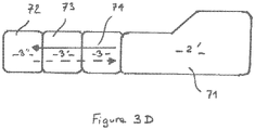
- the 3d figure represents another embodiment of the invention in which the complementary modules 3, 3', 3" are arranged to respectively project beams 74, 73, and 72 successively from a side face of the main dipped beam 71 at cut-off at 15°
- the harnesses of the complementary modules 3, 3', 3" thus complete the main harness.
- Such an embodiment is particularly interesting in that it can be advantageously implemented in relation to the turning radius (or angle at the steering wheel) of the vehicle to provide additional illumination of the main beam 71 in bends so keep on going.
- the solid line arrow illustrates the case where the driver begins a bend whose curvature first requires a small angle at the steering wheel then an increasingly large angle, successively switching on continuously (so as not to create a "hole” in the global beam), the first complementary module 3, emitting the beam 74, the second complementary module 3', emitting the beam 73, then finally, the third complementary module 3", emitting the beam 72.
- the intensity of the lighting of the complementary modules is controlled so that the first complementary module 3 lights up very quickly at maximum intensity at most a few hundred milliseconds to reach 100% of the flux then the second then the third.
- Such an embodiment makes it possible, at lower cost, to implement a lighting function designated by the English acronym “DBL: Dynamic Bending Light”.
- the invention also relates to a method for controlling the lighting of the complementary modules 3, 3' and 3′′ implemented by the control unit 5 to perform the “DBL” lighting function.
- the invention also relates to a method for controlling the lighting of the complementary modules 3, 3' and 3" implemented by the control unit 5, to perform the lighting function in tight bends or at designated intersections also by the Anglo-Saxon expression "Cornering Light” mainly used in urban areas and at low speeds.
- This additional lighting function illuminates the inside of the bend as long as the vehicle speed is below 40 km/h (urban driving, winding road, intersection, parking manoeuvre, etc.). This function is triggered following activation of the corresponding direction indicator or from a certain angle of rotation of the steering wheel.
- This function is usually performed by the fog lamp corresponding to the direction of the turn and which comes on or goes off according to the angle of rotation of the steering wheel.
- Such a function is designated “static” in that the fog lamp is static, not mobile in rotation (azimuth).
Claims (7)
- Fahrzeugscheinwerfer (1) mit einem Hauptbeleuchtungsmodul (2), das so angeordnet ist, dass es ein Hauptlichtbündel (71) entsprechend einem Abblendlicht aussendet, einer Vielzahl von benachbarten Zusatzbeleuchtungsmodulen (3, 3', 3"), die so angeordnet sind, dass sie jeweils ein Zusatzlichtbündel (74, 73, 72) aussenden, das sich von dem Hauptlichtbündel (71) unterscheidet, ein Mittel (4) zur Einstellung der Höhen- und Azimutausrichtung jedes der Beleuchtungsmodule (2, 2', 2", 3, 3', 3") und eine Steuereinheit (5), dadurch gekennzeichnet, dass das Einstellmittel die Einstellung der Höhen- und Azimutausrichtung jedes der ergänzenden Beleuchtungsmodule unabhängig voneinander ermöglicht, so dass mehrere unterschiedliche photometrische Funktionen realisiert werden können, und dass die komplementären Module (3, 3', 3") von der Steuereinheit (5) angeordnet und gesteuert werden, die in der Lage ist, die Beleuchtungsintensität und die Ausrichtung jedes der komplementären Beleuchtungsmodule zu steuern, um jeweils und nacheinander im Raum und in der Zeit ihre Strahlen (74, 73, und 72) von einer Seitenfläche des Hauptstrahls (71) aus in Abhängigkeit vom Drehwinkel des Lenkrads des Fahrzeugs (1), um eine kontinuierliche Zusatzbeleuchtung des Hauptstrahls (71) während einer Kurve zu erreichen.
- Scheinwerfer nach dem vorhergehenden Anspruch, dadurch gekennzeichnet, dass die Steuereinheit (5) geeignet ist, die Intensität der Beleuchtung der Zusatzmodule (3, 3', 3") so zu steuern, dass das erste Zusatzmodul (3) sofort mit maximaler Intensität leuchtet, dann das zweite (3') und dann das dritte (3"), um dem Fahrer des Fahrzeugs während der Kurve ein maximales Nachtsichtfeld zu bieten.
- Scheinwerfer nach dem vorhergehenden Anspruch, dadurch gekennzeichnet, dass die Steuereinheit (5) die Module ausgehend vom kurveninnersten Modul (3") in Richtung des Hauptmoduls (2) so steuert, dass sie bis zum Verlassen der Kurve allmählich ausgeschaltet werden.
- Verfahren zur Steuerung der Beleuchtung der Zusatzmodule (3, 3', 3") eines Scheinwerfers nach einem der Ansprüche 2 und 3, dadurch gekennzeichnet, dass es aus folgenden Schritten besteht:- die Lichtbündel (74, 73, 72) der Zusatzmodule (3, 3', 3") jeweils und nacheinander von einer Seitenfläche des Hauptabblendlichtbündels (71) aus in Abhängigkeit vom Drehwinkel des Lenkrads des Fahrzeugs (1) zu projizieren, um eine kontinuierliche Zusatzbeleuchtung des Hauptlichtbündels (71) am Anfang einer Kurve zu realisieren ;- die Beleuchtungsintensität der Zusatzmodule (3, 3', 3") so zu steuern, dass das erste Zusatzmodul (3) sofort mit maximaler Intensität aufleuchtet, dann das zweite (3') und dann das dritte (3"), so dass dem Fahrer des Fahrzeugs (1) während der Kurve ein maximales Nachtsichtfeld geboten wird ;- die Zusatzmodule (3, 3', 3") ausgehend vom kurveninnersten Zusatzmodul (3") in Richtung des Hauptbeleuchtungsmoduls (2) bis zum Verlassen der Kurve schrittweise auszuschalten.
- Verfahren zur Steuerung der Beleuchtung der Zusatzmodule (3, 3', 3") eines Scheinwerfers nach Anspruch 1, dadurch gekennzeichnet, dass es darin besteht, wenn sich das Fahrzeug bei einer Geschwindigkeit befindet, die geringer ist als eine bestimmte Geschwindigkeit:- die Lichtbündel (74, 73, 72) der Zusatzmodule (3, 3', 3") gleichzeitig zu projizieren, sobald ein bestimmter Drehwinkel des Lenkrads des Fahrzeugs (1) und/oder die Aktivierung des Fahrtrichtungsanzeigers erfasst wird, um eine Kreuzungsbeleuchtungsfunktion zu realisieren, die die Beleuchtung des Hauptlichtbündels (71) ergänzt;- allmähliches Ausschalten der Module (3, 3', 3") ausgehend vom kurveninnersten Modul (3") in Richtung des Hauptbeleuchtungsmoduls (2), wenn sich der Drehwinkel des Lenkrads einem Winkel von Null nähert.
- Verfahren nach dem vorhergehenden Anspruch, dadurch gekennzeichnet, dass alle Zusatzmodule gleichzeitig mit maximaler Leistung eingeschaltet werden, sobald ein Lenkraddrehwinkel und/oder die Aktivierung des Fahrtrichtungsanzeigers erkannt wird.
- Kraftfahrzeug (1) mit mindestens einem Fahrzeugscheinwerfer nach einem der Ansprüche 1 bis 3.
Applications Claiming Priority (2)
| Application Number | Priority Date | Filing Date | Title |
|---|---|---|---|
| FR1652688A FR3049523B1 (fr) | 2016-03-29 | 2016-03-29 | Projecteur de vehicule |
| PCT/FR2017/050638 WO2017168072A1 (fr) | 2016-03-29 | 2017-03-20 | Projecteur de véhicule |
Publications (2)
| Publication Number | Publication Date |
|---|---|
| EP3436307A1 EP3436307A1 (de) | 2019-02-06 |
| EP3436307B1 true EP3436307B1 (de) | 2022-05-11 |
Family
ID=56372987
Family Applications (1)
| Application Number | Title | Priority Date | Filing Date |
|---|---|---|---|
| EP17716952.1A Active EP3436307B1 (de) | 2016-03-29 | 2017-03-20 | Fahrzeugscheinwerfer |
Country Status (4)
| Country | Link |
|---|---|
| EP (1) | EP3436307B1 (de) |
| CN (1) | CN109070790B (de) |
| FR (1) | FR3049523B1 (de) |
| WO (1) | WO2017168072A1 (de) |
Family Cites Families (8)
| Publication number | Priority date | Publication date | Assignee | Title |
|---|---|---|---|---|
| JP2001270383A (ja) | 2000-03-28 | 2001-10-02 | Koito Mfg Co Ltd | 車両用前照灯システム |
| JP4168890B2 (ja) * | 2003-09-19 | 2008-10-22 | 市光工業株式会社 | 車両用灯具 |
| DE102004055882A1 (de) * | 2004-11-19 | 2006-06-01 | Audi Ag | Kraftfahrzeug mit einer Beleuchtungseinrichtung umfassend ein Steuergerät und ein über das Steuergerät zum Ausleuchten einer Kurve in Abhängigkeit des über einen Lenkwinkelsensor erfassten Lenkwinkels ansteuerbares Leuchtmittel |
| JP2008074327A (ja) * | 2006-09-25 | 2008-04-03 | Mazda Motor Corp | 車両用照明装置 |
| DE102007038563A1 (de) * | 2007-08-16 | 2009-02-19 | Daimler Ag | Beleuchtungssystem für ein Kraftfahrzeug |
| JP4997052B2 (ja) * | 2007-10-01 | 2012-08-08 | 株式会社小糸製作所 | 車両用前照灯 |
| FR2955729B1 (fr) * | 2010-01-22 | 2012-12-14 | Valeo Vision | Procede de detection pour un vehicule automobile |
| CN102582508A (zh) * | 2012-03-19 | 2012-07-18 | 中国汽车技术研究中心 | 一种车辆夜间弯道辅助与视觉增强装置及其方法 |
-
2016
- 2016-03-29 FR FR1652688A patent/FR3049523B1/fr not_active Expired - Fee Related
-
2017
- 2017-03-20 EP EP17716952.1A patent/EP3436307B1/de active Active
- 2017-03-20 WO PCT/FR2017/050638 patent/WO2017168072A1/fr active Application Filing
- 2017-03-20 CN CN201780020932.4A patent/CN109070790B/zh active Active
Also Published As
| Publication number | Publication date |
|---|---|
| FR3049523B1 (fr) | 2020-01-31 |
| EP3436307A1 (de) | 2019-02-06 |
| FR3049523A1 (fr) | 2017-10-06 |
| CN109070790A (zh) | 2018-12-21 |
| CN109070790B (zh) | 2022-07-19 |
| WO2017168072A1 (fr) | 2017-10-05 |
Similar Documents
| Publication | Publication Date | Title |
|---|---|---|
| EP2690352B1 (de) | Adaptives Beleuchtungssystem für Kraftfahrzeug | |
| EP1748251B1 (de) | Beleuchtungsvorrichtung für Kraftfahrzeuge | |
| EP2957464B1 (de) | Drehbares beleuchtungs- und/oder signalisierungsmodul | |
| EP2128521B1 (de) | Kraftfahrzeugscheinwerfer, der in der Lage ist, einen schwenkbaren Lichtstrahl abzugeben | |
| EP3115256A1 (de) | Kontrollverfahren eines lichtbündels, und entsprechendes beleuchtungs- und/oder signalisierungsmodul | |
| EP1449716B1 (de) | Beleuchtungsvorrichtung für ein Kraftfahrzeug bei Kurvenfahrt | |
| EP2244007A1 (de) | Optische Vorrichtung für Kraftfahrzeug | |
| FR2811276A1 (fr) | Systeme de phares pour vehicules et procede pour leur commande | |
| EP2546569B1 (de) | Multifunktions-Beleuchtungs-/Signalisierungsvorrichtung für Kraftfahrzeug | |
| EP2990264A2 (de) | Steuerungsverfahren eins lichtstrahls und entsprechendes beleuchtungs- und/oder signalisierungsmodul | |
| EP2301801A1 (de) | Verfahren zur Steuerung eines Fahrzeugscheinwerfers | |
| EP3224083A1 (de) | Fahrzeugscheinwerfer | |
| EP3152480A1 (de) | Beleuchtungsvorrichtung mit beweglicher linse für kraftfahrzeug | |
| EP1502814B2 (de) | Scheinwerfer für Abblend- und Kurvenlicht für Kraftfahrzeuge | |
| EP3453946A1 (de) | Leuchtmodul für kraftfahrzeug, und beleuchtungs- und/oder signalisierungsvorrichtung, die mit einem solchen modul ausgestattet ist | |
| EP3436307B1 (de) | Fahrzeugscheinwerfer | |
| EP2988972B1 (de) | Verfahren zur steuerung eines regulierbaren beleuchtungssystems für ein trägerfahrzeug und reguliebares beleuchtungsystem | |
| EP1870283B1 (de) | Scheinwerfereinheit mit drei Funktionen für Kraftfahrzeuge | |
| EP3455102B1 (de) | Beleuchtungssystem und verfahren für ein kraftfahrzeug | |
| EP1366955B1 (de) | Antiblendsicherheitsvorrichtung für Kfz-Scheinwerfer | |
| EP2168812B1 (de) | Beleuchtungssystem für ein kraftfahrzeug, das die emission eines abblendlichts verändern kann | |
| EP1619440A1 (de) | Beleuchtungssystem für Kraftfahrzeuge mit Überlappung von Lichtbündeln | |
| EP1762431A1 (de) | Beleuchtungsvorrichtung für Kraftfahrzeuge | |
| FR2845330A1 (fr) | Dispositif d'eclairage et/ou de signalisation du type projecteur pour vehicule automobile | |
| EP1953039A2 (de) | Multifunktionsbeleuchtungsvorrichtung für Kraftfahrzeug |
Legal Events
| Date | Code | Title | Description |
|---|---|---|---|
| STAA | Information on the status of an ep patent application or granted ep patent |
Free format text: STATUS: UNKNOWN |
|
| STAA | Information on the status of an ep patent application or granted ep patent |
Free format text: STATUS: THE INTERNATIONAL PUBLICATION HAS BEEN MADE |
|
| PUAI | Public reference made under article 153(3) epc to a published international application that has entered the european phase |
Free format text: ORIGINAL CODE: 0009012 |
|
| STAA | Information on the status of an ep patent application or granted ep patent |
Free format text: STATUS: REQUEST FOR EXAMINATION WAS MADE |
|
| 17P | Request for examination filed |
Effective date: 20181005 |
|
| AK | Designated contracting states |
Kind code of ref document: A1 Designated state(s): AL AT BE BG CH CY CZ DE DK EE ES FI FR GB GR HR HU IE IS IT LI LT LU LV MC MK MT NL NO PL PT RO RS SE SI SK SM TR |
|
| AX | Request for extension of the european patent |
Extension state: BA ME |
|
| STAA | Information on the status of an ep patent application or granted ep patent |
Free format text: STATUS: REQUEST FOR EXAMINATION WAS MADE |
|
| DAV | Request for validation of the european patent (deleted) | ||
| DAX | Request for extension of the european patent (deleted) | ||
| RAP1 | Party data changed (applicant data changed or rights of an application transferred) |
Owner name: PSA AUTOMOBILES SA |
|
| GRAP | Despatch of communication of intention to grant a patent |
Free format text: ORIGINAL CODE: EPIDOSNIGR1 |
|
| STAA | Information on the status of an ep patent application or granted ep patent |
Free format text: STATUS: GRANT OF PATENT IS INTENDED |
|
| INTG | Intention to grant announced |
Effective date: 20220121 |
|
| GRAS | Grant fee paid |
Free format text: ORIGINAL CODE: EPIDOSNIGR3 |
|
| GRAA | (expected) grant |
Free format text: ORIGINAL CODE: 0009210 |
|
| STAA | Information on the status of an ep patent application or granted ep patent |
Free format text: STATUS: THE PATENT HAS BEEN GRANTED |
|
| AK | Designated contracting states |
Kind code of ref document: B1 Designated state(s): AL AT BE BG CH CY CZ DE DK EE ES FI FR GB GR HR HU IE IS IT LI LT LU LV MC MK MT NL NO PL PT RO RS SE SI SK SM TR |
|
| REG | Reference to a national code |
Ref country code: GB Ref legal event code: FG4D Free format text: NOT ENGLISH |
|
| REG | Reference to a national code |
Ref country code: DE Ref legal event code: R084 Ref document number: 602017057298 Country of ref document: DE Ref country code: CH Ref legal event code: EP |
|
| REG | Reference to a national code |
Ref country code: AT Ref legal event code: REF Ref document number: 1491147 Country of ref document: AT Kind code of ref document: T Effective date: 20220515 |
|
| REG | Reference to a national code |
Ref country code: DE Ref legal event code: R096 Ref document number: 602017057298 Country of ref document: DE |
|
| REG | Reference to a national code |
Ref country code: IE Ref legal event code: FG4D Free format text: LANGUAGE OF EP DOCUMENT: FRENCH |
|
| REG | Reference to a national code |
Ref country code: GB Ref legal event code: 746 Effective date: 20220531 |
|
| REG | Reference to a national code |
Ref country code: LT Ref legal event code: MG9D |
|
| REG | Reference to a national code |
Ref country code: NL Ref legal event code: MP Effective date: 20220511 |
|
| REG | Reference to a national code |
Ref country code: AT Ref legal event code: MK05 Ref document number: 1491147 Country of ref document: AT Kind code of ref document: T Effective date: 20220511 |
|
| PG25 | Lapsed in a contracting state [announced via postgrant information from national office to epo] |
Ref country code: SE Free format text: LAPSE BECAUSE OF FAILURE TO SUBMIT A TRANSLATION OF THE DESCRIPTION OR TO PAY THE FEE WITHIN THE PRESCRIBED TIME-LIMIT Effective date: 20220511 Ref country code: PT Free format text: LAPSE BECAUSE OF FAILURE TO SUBMIT A TRANSLATION OF THE DESCRIPTION OR TO PAY THE FEE WITHIN THE PRESCRIBED TIME-LIMIT Effective date: 20220912 Ref country code: NO Free format text: LAPSE BECAUSE OF FAILURE TO SUBMIT A TRANSLATION OF THE DESCRIPTION OR TO PAY THE FEE WITHIN THE PRESCRIBED TIME-LIMIT Effective date: 20220811 Ref country code: NL Free format text: LAPSE BECAUSE OF FAILURE TO SUBMIT A TRANSLATION OF THE DESCRIPTION OR TO PAY THE FEE WITHIN THE PRESCRIBED TIME-LIMIT Effective date: 20220511 Ref country code: LT Free format text: LAPSE BECAUSE OF FAILURE TO SUBMIT A TRANSLATION OF THE DESCRIPTION OR TO PAY THE FEE WITHIN THE PRESCRIBED TIME-LIMIT Effective date: 20220511 Ref country code: HR Free format text: LAPSE BECAUSE OF FAILURE TO SUBMIT A TRANSLATION OF THE DESCRIPTION OR TO PAY THE FEE WITHIN THE PRESCRIBED TIME-LIMIT Effective date: 20220511 Ref country code: GR Free format text: LAPSE BECAUSE OF FAILURE TO SUBMIT A TRANSLATION OF THE DESCRIPTION OR TO PAY THE FEE WITHIN THE PRESCRIBED TIME-LIMIT Effective date: 20220812 Ref country code: FI Free format text: LAPSE BECAUSE OF FAILURE TO SUBMIT A TRANSLATION OF THE DESCRIPTION OR TO PAY THE FEE WITHIN THE PRESCRIBED TIME-LIMIT Effective date: 20220511 Ref country code: ES Free format text: LAPSE BECAUSE OF FAILURE TO SUBMIT A TRANSLATION OF THE DESCRIPTION OR TO PAY THE FEE WITHIN THE PRESCRIBED TIME-LIMIT Effective date: 20220511 Ref country code: BG Free format text: LAPSE BECAUSE OF FAILURE TO SUBMIT A TRANSLATION OF THE DESCRIPTION OR TO PAY THE FEE WITHIN THE PRESCRIBED TIME-LIMIT Effective date: 20220811 Ref country code: AT Free format text: LAPSE BECAUSE OF FAILURE TO SUBMIT A TRANSLATION OF THE DESCRIPTION OR TO PAY THE FEE WITHIN THE PRESCRIBED TIME-LIMIT Effective date: 20220511 |
|
| PG25 | Lapsed in a contracting state [announced via postgrant information from national office to epo] |
Ref country code: RS Free format text: LAPSE BECAUSE OF FAILURE TO SUBMIT A TRANSLATION OF THE DESCRIPTION OR TO PAY THE FEE WITHIN THE PRESCRIBED TIME-LIMIT Effective date: 20220511 Ref country code: PL Free format text: LAPSE BECAUSE OF FAILURE TO SUBMIT A TRANSLATION OF THE DESCRIPTION OR TO PAY THE FEE WITHIN THE PRESCRIBED TIME-LIMIT Effective date: 20220511 Ref country code: LV Free format text: LAPSE BECAUSE OF FAILURE TO SUBMIT A TRANSLATION OF THE DESCRIPTION OR TO PAY THE FEE WITHIN THE PRESCRIBED TIME-LIMIT Effective date: 20220511 Ref country code: IS Free format text: LAPSE BECAUSE OF FAILURE TO SUBMIT A TRANSLATION OF THE DESCRIPTION OR TO PAY THE FEE WITHIN THE PRESCRIBED TIME-LIMIT Effective date: 20220911 |
|
| PG25 | Lapsed in a contracting state [announced via postgrant information from national office to epo] |
Ref country code: SM Free format text: LAPSE BECAUSE OF FAILURE TO SUBMIT A TRANSLATION OF THE DESCRIPTION OR TO PAY THE FEE WITHIN THE PRESCRIBED TIME-LIMIT Effective date: 20220511 Ref country code: SK Free format text: LAPSE BECAUSE OF FAILURE TO SUBMIT A TRANSLATION OF THE DESCRIPTION OR TO PAY THE FEE WITHIN THE PRESCRIBED TIME-LIMIT Effective date: 20220511 Ref country code: RO Free format text: LAPSE BECAUSE OF FAILURE TO SUBMIT A TRANSLATION OF THE DESCRIPTION OR TO PAY THE FEE WITHIN THE PRESCRIBED TIME-LIMIT Effective date: 20220511 Ref country code: EE Free format text: LAPSE BECAUSE OF FAILURE TO SUBMIT A TRANSLATION OF THE DESCRIPTION OR TO PAY THE FEE WITHIN THE PRESCRIBED TIME-LIMIT Effective date: 20220511 Ref country code: DK Free format text: LAPSE BECAUSE OF FAILURE TO SUBMIT A TRANSLATION OF THE DESCRIPTION OR TO PAY THE FEE WITHIN THE PRESCRIBED TIME-LIMIT Effective date: 20220511 Ref country code: CZ Free format text: LAPSE BECAUSE OF FAILURE TO SUBMIT A TRANSLATION OF THE DESCRIPTION OR TO PAY THE FEE WITHIN THE PRESCRIBED TIME-LIMIT Effective date: 20220511 |
|
| REG | Reference to a national code |
Ref country code: DE Ref legal event code: R097 Ref document number: 602017057298 Country of ref document: DE |
|
| PLBE | No opposition filed within time limit |
Free format text: ORIGINAL CODE: 0009261 |
|
| STAA | Information on the status of an ep patent application or granted ep patent |
Free format text: STATUS: NO OPPOSITION FILED WITHIN TIME LIMIT |
|
| PG25 | Lapsed in a contracting state [announced via postgrant information from national office to epo] |
Ref country code: AL Free format text: LAPSE BECAUSE OF FAILURE TO SUBMIT A TRANSLATION OF THE DESCRIPTION OR TO PAY THE FEE WITHIN THE PRESCRIBED TIME-LIMIT Effective date: 20220511 |
|
| 26N | No opposition filed |
Effective date: 20230214 |
|
| PGFP | Annual fee paid to national office [announced via postgrant information from national office to epo] |
Ref country code: FR Payment date: 20230222 Year of fee payment: 7 |
|
| PG25 | Lapsed in a contracting state [announced via postgrant information from national office to epo] |
Ref country code: SI Free format text: LAPSE BECAUSE OF FAILURE TO SUBMIT A TRANSLATION OF THE DESCRIPTION OR TO PAY THE FEE WITHIN THE PRESCRIBED TIME-LIMIT Effective date: 20220511 |
|
| PG25 | Lapsed in a contracting state [announced via postgrant information from national office to epo] |
Ref country code: MC Free format text: LAPSE BECAUSE OF FAILURE TO SUBMIT A TRANSLATION OF THE DESCRIPTION OR TO PAY THE FEE WITHIN THE PRESCRIBED TIME-LIMIT Effective date: 20220511 |
|
| REG | Reference to a national code |
Ref country code: CH Ref legal event code: PL |
|
| REG | Reference to a national code |
Ref country code: BE Ref legal event code: MM Effective date: 20230331 |
|
| PG25 | Lapsed in a contracting state [announced via postgrant information from national office to epo] |
Ref country code: LU Free format text: LAPSE BECAUSE OF NON-PAYMENT OF DUE FEES Effective date: 20230320 |
|
| REG | Reference to a national code |
Ref country code: IE Ref legal event code: MM4A |
|
| PG25 | Lapsed in a contracting state [announced via postgrant information from national office to epo] |
Ref country code: LI Free format text: LAPSE BECAUSE OF NON-PAYMENT OF DUE FEES Effective date: 20230331 Ref country code: IT Free format text: LAPSE BECAUSE OF FAILURE TO SUBMIT A TRANSLATION OF THE DESCRIPTION OR TO PAY THE FEE WITHIN THE PRESCRIBED TIME-LIMIT Effective date: 20220511 Ref country code: IE Free format text: LAPSE BECAUSE OF NON-PAYMENT OF DUE FEES Effective date: 20230320 Ref country code: CH Free format text: LAPSE BECAUSE OF NON-PAYMENT OF DUE FEES Effective date: 20230331 |
|
| PG25 | Lapsed in a contracting state [announced via postgrant information from national office to epo] |
Ref country code: BE Free format text: LAPSE BECAUSE OF NON-PAYMENT OF DUE FEES Effective date: 20230331 |
|
| REG | Reference to a national code |
Ref country code: DE Ref legal event code: R081 Ref document number: 602017057298 Country of ref document: DE Owner name: STELLANTIS AUTO SAS, FR Free format text: FORMER OWNER: PSA AUTOMOBILES SA, POISSY, FR |
|
| PGFP | Annual fee paid to national office [announced via postgrant information from national office to epo] |
Ref country code: DE Payment date: 20240220 Year of fee payment: 8 Ref country code: GB Payment date: 20240221 Year of fee payment: 8 |