EP1170547B2 - Elliptischer Scheinwerfer für eine Strassenbeleuchtung mit verbesserter Niedrig-Photometrie - Google Patents
Elliptischer Scheinwerfer für eine Strassenbeleuchtung mit verbesserter Niedrig-Photometrie Download PDFInfo
- Publication number
- EP1170547B2 EP1170547B2 EP01401648A EP01401648A EP1170547B2 EP 1170547 B2 EP1170547 B2 EP 1170547B2 EP 01401648 A EP01401648 A EP 01401648A EP 01401648 A EP01401648 A EP 01401648A EP 1170547 B2 EP1170547 B2 EP 1170547B2
- Authority
- EP
- European Patent Office
- Prior art keywords
- edge
- headlight
- headlight according
- light
- lens
- Prior art date
- Legal status (The legal status is an assumption and is not a legal conclusion. Google has not performed a legal analysis and makes no representation as to the accuracy of the status listed.)
- Expired - Lifetime
Links
- 238000005375 photometry Methods 0.000 title 1
- 230000003287 optical effect Effects 0.000 claims description 31
- 230000000295 complement effect Effects 0.000 claims 1
- 239000002184 metal Substances 0.000 claims 1
- 230000005855 radiation Effects 0.000 description 7
- 238000013459 approach Methods 0.000 description 4
- 238000004040 coloring Methods 0.000 description 3
- 230000000630 rising effect Effects 0.000 description 3
- 230000000007 visual effect Effects 0.000 description 3
- 239000003086 colorant Substances 0.000 description 2
- 230000014759 maintenance of location Effects 0.000 description 2
- 229910000831 Steel Inorganic materials 0.000 description 1
- 240000008042 Zea mays Species 0.000 description 1
- 230000015572 biosynthetic process Effects 0.000 description 1
- 230000007547 defect Effects 0.000 description 1
- 230000000694 effects Effects 0.000 description 1
- 239000011521 glass Substances 0.000 description 1
- 238000010438 heat treatment Methods 0.000 description 1
- 238000005304 joining Methods 0.000 description 1
- 238000004519 manufacturing process Methods 0.000 description 1
- 239000000463 material Substances 0.000 description 1
- 238000000034 method Methods 0.000 description 1
- 230000000116 mitigating effect Effects 0.000 description 1
- 230000000750 progressive effect Effects 0.000 description 1
- 239000010959 steel Substances 0.000 description 1
- 230000007704 transition Effects 0.000 description 1
Images


Classifications
-
- F—MECHANICAL ENGINEERING; LIGHTING; HEATING; WEAPONS; BLASTING
- F21—LIGHTING
- F21S—NON-PORTABLE LIGHTING DEVICES; SYSTEMS THEREOF; VEHICLE LIGHTING DEVICES SPECIALLY ADAPTED FOR VEHICLE EXTERIORS
- F21S41/00—Illuminating devices specially adapted for vehicle exteriors, e.g. headlamps
- F21S41/40—Illuminating devices specially adapted for vehicle exteriors, e.g. headlamps characterised by screens, non-reflecting members, light-shielding members or fixed shades
- F21S41/43—Illuminating devices specially adapted for vehicle exteriors, e.g. headlamps characterised by screens, non-reflecting members, light-shielding members or fixed shades characterised by the shape thereof
Definitions
- the present invention generally relates to projectors of the elliptical genre for motor vehicles, designed to generate a driving beam.
- a projector of the elliptical kind mainly comprises a recuperating mirror and concentrator of the ellipsoidal kind, having a first focal region in which is placed a light source, such as the filament of an incandescent lamp or the arc of a discharge lamp, and a second focal region in which a light concentration spot is formed after reflecting light from the source onto the mirror.
- a projector also comprises a convergent lens, typically plane-convex, focused in the vicinity of the second focal region of the mirror and capable of projecting on the road the aforementioned light spot.
- Such a projector is well suited to obtaining a beam delimited by an upper cut, such as a passing beam.
- an upper cut such as a passing beam.
- a type of headlight to form a driving beam, that is to say a beam having a concentration point in the axis of the road, but also a certain width and a certain thickness.
- One solution for reducing the size of the lamp hole is to mount the lamp further back, relative to the general direction of light emission, so that only its bulb has to go through the lamp hole, but the base is located further back.
- the lamp-hole size can be reduced, even if a safety distance must be respected around the bulb of the lamp to avoid unwanted heating of the mirror in this region.
- a short focal distance is the direct consequence of a minimization of the lateral and vertical dimensions of the headlamp. and on the other hand the recoil of the lamp with respect to the mirror, causing the light source to be further back in the mirror.
- This short focal length causes the mirror to generate, due to the non-point dimensions of the source (typically a cylinder of some 5 mm in length and about 1 mm in diameter) a significant spot of light concentration.
- the source typically a cylinder of some 5 mm in length and about 1 mm in diameter
- One solution to overcome this drawback could be to provide at the light spot before projection cache similar to those used in the crossing headlamps, but in an upside down position, so as to obscure the light illuminating the road too close to the vehicle.
- the present invention provides an elliptical projector for a motor vehicle according to claim 1.
- the present invention aims to overcome these disadvantages and limitations of the state of the art.
- the present invention aims to provide means capable of ensuring a gradual decrease in light as this light illuminates areas of the road closer and closer to the vehicle.
- Another object of the invention is to achieve this objective without giving rise to undesirable coloring of the light due to the fact that, by nature, a lens deviates differently the radiation according to the wavelength thereof (phenomenon of chromatism).
- the present invention aims at resorting to an occultation of the light which is carried out at a distance from the focal surface of the lens (a plane for a perfect lens - but a kind of dome, whose focus FL constitutes the summit, for an imperfect lens such as a spherical plane). But at the same time it aims to ensure that, despite such a defocusing of the cache, there is no witnessing phenomena of undesirable coloring of the beam.
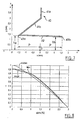
- a projector which includes in itself known manner a lamp 10 constituting a light source, in this case by its incandescent filament 11.
- This lamp is mounted in a bottom hole 21 of a mirror 20 of the elliptical kind, such as an ellipsoid of revolution.
- the filament 11 is disposed in the first focal region F1 of the mirror, so as to form in the second focal region F2 thereof a light spot.
- the projector also comprises a lens 30, here a plano-convex lens whose axis is coincident with the major axis of the mirror passing through the first and second focal regions (this axis, designated by xx, being hereinafter referred to as ""optical axis of the projector") and whose focus FL is at the second focal region F2 of the mirror.
- the lens 30 projects to infinity on the road the light spot present in the region F2, as described above with reference to the figure 1 .
- this headlamp is equipped with a specific mask 40 which is placed above the horizontal plane passing through the optical axis xx and having the property of having at least two active edges to selectively obscure certain components of the light. from the mirror (in contrast to conventional covers used in crossover projectors, which generally extend vertically and have a single upper - optically active edge.
- this cache comprises an amount 41 having, if necessary, a concealment role but whose main purpose is to ensure the mechanical retention of the useful part of the cover on the structure of the projector (by example on an intermediate part of the projector, not described but conventional in itself, coming together to fix the mirror and the lens).
- the cover 40 may be made in one piece with this intermediate piece.
- the cover 40 also includes an oblique occultation portion 42, which extends downwardly and rearwardly from the projector, from a front edge 43b, located vertically above the point F constituting at the same time the second focal point F2 of the mirror 20 and the focus FL of the lens, and towards a rear edge 43a ("before” and “backward” are understood throughout the description with respect to the general direction of emission defined by the optical axis xx). It is thus observed that the two edges 43a, 43b are spaced along the optical axis.
- the concealment portion of the cover is a profile extending in the horizontal direction and transverse to the optical axis xx, that is to say that the edges 43a, 43b are themselves horizontal and parallel to the optical axis.
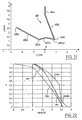
- the figure 3 illustrates, by the lines of a set of light rays R, that the two edges 43a, 43b of the occulting part 42 play two independent roles vis-à-vis the light radiation, the rear edge 43a effecting an occultation (zone shadow Z0) at a given level for the descending rays while the leading edge 43b performs ZO concealment at a determined level for the rising rays.
- This form of new cache has been designed primarily to seek a gradual attenuation of light. More precisely, knowing that there is a variety of light rays, amounts or descendants, which participate in the formation of light at a given height in the beam, such a cache allows for a gradual occultation of light, acting differently on the rising rays and on the descending rays.
- the figure 4 drawings is a graph whose abscissa indicates the downward slope of the light (0 ° corresponding to the horizon, and the indicated values corresponding to the inclination of the light below the horizon), and of which the ordinate indicates the proportion of the light transmitted at the output of the projector (downstream of the lens 30) as a function of the aforementioned inclination, the number 1 indicating that all the light passes and the digit 0 indicating that no light passes .
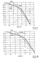
- the figure 5 illustrates a second embodiment of the invention, to reduce chromaticism especially in the lower region of the beam.
- the cache 40 of the figure 5 has a generally horizontal occulting portion 42 extending above the focus F, a first edge 43a is located rearwardly relative to said focus and a second edge 43b is located forward relative to the same focus.
- the figure 7 illustrates a third embodiment of the cache, which is different from that of the figure 5 mainly in that the cover 42 has a very slight inclination, descending forwards, relative to the horizontal plane passing through the optical axis xx.
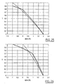
- FIGS 9 and 10 illustrate, for their part, the attenuation behavior obtained for different settings of the caches of the figures 5 and 7 . It is observed that one can play on the angle from which the attenuation begins (here 0 °, to leave a greater amount of light in the axis of the road.
- the figure 11 illustrates a fourth embodiment of a cache according to the invention, wherein the occultation portion 42 is characterized by three useful edges 43a, 43b, 43c.
- the cover as a whole has the shape of an asymmetrical "V", with a high rear edge 43a, a low intermediate edge 43b and a high front edge 43c, these edges being interconnected in this case by portions 42a, 42b with straight cross-sections.
- the front edge 43c is here at perpendicular to the focus F, the entire occulting portion 42 extending rearwardly from this focus.
- the rear edge 43a acts on the radiation which is more downwardly inclined than the portion 42a
- the front edge 43c acts on the radiation which is more upwardly inclined than the portion 42b
- the intermediate edge 43b acts on the radiation having an intermediate inclination between these extreme inclinations.
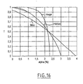
- the figure 14 illustrates a fifth embodiment of the invention, similar to that of the figure 11 but which is distinguished by the fact that the portions 42a, 42b of the cache obscuration part meet not at a sharp edge 43b, but at a smooth curve transition (zone 42c, for example section shaped arcuate).
- edges 43a, 43c play the same roles as before, but at the edge 43b is substituted for an area 42c constituting in fact an infinity of blackout edges 43b, variable according to the inclination of the neighboring light.
- the low point of the zone 42c constitutes an occulting edge vis-à-vis the radiation that propagates horizontally.
- this embodiment allows to leave a greater amount of light near the vicinity of the road axis, for a good visual comfort of the driver.
- the curved edge 43b defined by the portion 42c of the cache extends to the front free end of said cache, the portion 42b thereof does not exist in this case.
- said free end will, depending on the configurations, be operative or inoperative.
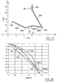
- the sixth embodiment, illustrated on the figure 17 is getting closer to that of the figure 11 in that the occulting portion 42 has three optically active sharp edges 43a, 43b and 43c, respectively.
- the essential difference lies in that the front edge 43c on the one hand is at a height close to that of the intermediate edge 43b above the optical axis xx, and on the other hand is forward with respect to the position of the focus F on said axis xx.
- the objective here is to obtain attenuation curves similar to those of figures 12 and following, but limiting or avoiding at the same time undesirable colorings of the beam in particular in its lower region.
- V shape of the portions 42b1, 42b2 which join the edges 43, 43c is here inoperative; it could for example be also a straight line, or a concavity arc of a circle facing down.
- the corresponding mitigation laws are illustrated on the figure 18 .
- a general law is observed which reinforces the light near the axis of the road, and at the same time the near laws for red, blue and green, so that the chromaticism is substantially reduced.
- the seventh embodiment illustrated on the figure 19 constitutes an intermediate achievement between that of figure 14 (rounded edge) and that of the figure 17 (overall arrangement of the edges).
- the occulting portion 42 has a rear edge 43a, a front edge 43c and a curved intermediate region 42c which defines an infinity of blackout edges 43c, according to the inclination of the light which passes in its vicinity (see above).
- the shape of the attenuation obtained is illustrated on the figure 20 , and shows an intermediate behavior between those of the caches of figures 14 and 17 .
- the figure 21 illustrates an eighth embodiment of the invention, which is similar in principle to that of the figure 17 , with a different setting.
- the attenuation achieved is practically nil down to about 1 ° below the horizon, in order to retain more light in the axis of the road, and then adopt a similar pace, in a limited angular interval, to that of the figure 18 , and this for all wavelengths so that no coloration of the beam at the beginning of the attenuation is encountered.
- the ninth embodiment of the invention illustrated on the figure 23 as for it the principle illustrated on the figure 19 an essential difference being that the portion 42b which joins the curved intermediate edge 43b and the front edge 43c is slightly inclined upwards, and shorter than in the case of the figure 19 and at the same time the portion 42a is more inclined.
- the shape of the attenuation obtained is illustrated on the figure 24 .
- the cover 40 it is possible to design the cover 40 to effect an attenuation from negative inclination values (rising light) of the light (in particular in the case where the maximum concentration of the beam in the absence of a cache is not in the the axis of the road (0 °), but slightly above it (for example, at about 1 ° above), in particular, one can parameterize the embodiment of the figure 5 in order to obtain an attenuation that begins for projected light inclination values of the order of -1 °. Examples of such attenuations are illustrated in the Figures 25 and 26 drawings.
- the corresponding figures have been indicated in millimeters.
- the attenuation curves have been modeled with the forms of caches as precisely illustrated, for an example a glass lens 30 with flat inner face and spherical outer surface, with a useful radius of the lens of 72 mm, a median draw 44 mm, a print of 44.5 mm in the red and a print of 43.5 mm in the blue.
- the various exemplary embodiments illustrated show that it is generally possible to achieve it by simply folding a thin sheet such as a steel sheet. Any other manufacturing technique and any other material can of course be considered, depending in particular on the required accuracy and resistance to the high temperature that prevails within such a projector.
- caches all having a uniform cross section along their horizontal extent transverse to the axis xx, it is of course possible to vary this section, in shape, in size, in position, etc ... as one moves along the cache horizontally and transversely to the axis xx.
Landscapes
- Engineering & Computer Science (AREA)
- General Engineering & Computer Science (AREA)
- Non-Portable Lighting Devices Or Systems Thereof (AREA)
Claims (17)
- Ellipsoid-Scheinwerfer für Kraftfahrzeuge, mit einem strahlungssammelnden und -bündelnden Reflektor (20) vom ellipsoiden Typ, der einen ersten Brennweitenbereich (F1), in dem eine Lichtquelle (11) angeordnet ist, und einen zweiten Brennweitenbereich (F2) aufweist, in dem sich ein konzentrierter Lichtfleck nach Reflexion des von der Lichtquelle abgegebenen Lichts am Reflektor bildet, und der ferner eine in der Nähe des zweiten Brennweitenbereichs des Reflektors fokussierte Sammellinse (30) aufweist, die den konzentrierten Lichtfleck auf die Straße zu projizieren vermag, wobei der Reflektor und die Linse eine optische Achse (x-x) des Scheinwerfers definieren und der Scheinwerfer ferner eine Blende (42) umfasst, die einen Teil des Lichts abzuschatten vermag, das sich zwischen dem Reflektor und der Linse ausbreitet, und in ihrer Gesamtheit über dem zweiten Brennweitenbereich (F2) angeordnet ist, dadurch gekennzeichnet, dass die Blende (42) wenigstens zwei jeweils einen Rand bildende Abschattungsbereiche (43a, 43b) besitzt, die in Richtung der optischen Achse voneinander beabstandet sind und jeweils gleichzeitig einen bestimmten Teil des Lichts abzuschatten vermögen, wobei einer (43b) der Ränder im Wesentlichen lotrecht zu einem Brennpunkt (F) der Linse angeordnet ist oder die Ränder (43a, 43b) hinter bzw. vor dem Brennpunkt (F) der Linse in Richtung der optischen Achse angeordnet sind, wobei der Scheinwerfer einen eigenständigen Fernlichtscheinwerfer bildet oder einen Aufschalt-Fernlichtscheinwerfer für ein Abblendlichtbündel.
- Scheinwerfer nach Anspruch 1,
dadurch gekennzeichnet, dass die voneinander beabstandeten Abschattungsbereiche jeweils einen scharfkantigen Rand (43a, 43b) bilden. - Scheinwerfer nach Anspruch 1,
dadurch gekennzeichnet, dass die voneinander beabstandeten Abschattungsbereiche jeweils einen gekrümmten Rand bilden. - Scheinwerfer nach Anspruch 1,
dadurch gekennzeichnet, dass die voneinander beabstandeten Abschattungsbereiche einen scharfkantigen Rand (43a) bzw. einen gekrümmten Rand (43c) bilden. - Scheinwerfer nach einem der Ansprüche 2 bis 4,
dadurch gekennzeichnet, dass die beiden Ränder (43a, 43b) auf gleicher Höhe liegen. - Scheinwerfer nach einem der Ansprüche 2 bis 4,
dadurch gekennzeichnet, dass die Ränder (43a, 43b) auf unterschiedlicher Höhe liegen. - Scheinwerfer nach Anspruch 6,
dadurch gekennzeichnet, dass ein vorderer Rand (43b) tiefer liegt als der hintere Rand (43a). - Scheinwerfer nach einem der vorhergehenden Ansprüche,
dadurch gekennzeichnet, dass der im Wesentlichen lotrecht zum Brennpunkt der Linse angeordnete Rand der vordere Rand (43b) ist. - Scheinwerfer nach einem der vorhergehenden Ansprüche,
dadurch gekennzeichnet, dass die Ränder (43a, 43b) in Richtung der optischen Achse im Wesentlichen in gleicher Entfernung zum Brennpunkt (F) der Linse liegen. - Scheinwerfer nach einem der Ansprüche 2 bis 9,
dadurch gekennzeichnet, dass die Blende einen dritten mittleren Abschattungsbereich (43b) zwischen dem ersten und dem zweiten Abschattungsbereich (43a, 43c) aufweist. - Scheinwerfer nach Anspruch 10,
dadurch gekennzeichnet, dass der mittlere Abschattungsbereich (43b) einen scharfkantigen Rand bildet. - Scheinwerfer nach Anspruch 10,
dadurch gekennzeichnet, dass der mittlere Abschattungsbereich (43b) einen abgerundeten Rand bildet. - Scheinwerfer nach einem der Ansprüche 10 bis 12,
dadurch gekennzeichnet, dass sich der durch den dritten mittleren Abschattungsbereich gebildete Rand (43b) im Wesentlichen auf gleicher Höhe mit einem der beiden Abschattungsbereiche (43a, 43c) befindet. - Scheinwerfer nach einem der Ansprüche 10 bis 13,
dadurch gekennzeichnet, dass der durch den dritten mittleren Abschattungsbereich gebildete Rand (43b) tiefer liegt als jeder der beiden Abschattungsbereiche (43a, 43c). - Scheinwerfer nach einem der Ansprüche 1 bis 14,
dadurch gekennzeichnet, dass sich die Blende (42) in einer allgemein horizontalen Richtung quer zur optischen Achse (x-x) erstreckt und über ihre gesamte Erstreckung den gleichen vertikalen Querschnitt aufweist. - Scheinwerfer nach einem der Ansprüche 1 bis 14,
dadurch gekennzeichnet, dass sich die Blende (42) in einer allgemein horizontalen Richtung quer zur optischen Achse (x-x) erstreckt und einen vertikalen Querschnitt aufweist, der sich entlang ihrer Erstreckung ändert. - Scheinwerfer nach einem der Ansprüche 1 bis 16,
dadurch gekennzeichnet, dass die Blende (42) aus gefalztem Blech gefertigt ist.
Priority Applications (1)
| Application Number | Priority Date | Filing Date | Title |
|---|---|---|---|
| DE60131600T DE60131600T3 (de) | 2000-07-07 | 2001-06-21 | Elliptischer Scheinwerfer für eine Strassenbeleuchtung mit verbesserter Niedrig-Photometrie |
Applications Claiming Priority (2)
| Application Number | Priority Date | Filing Date | Title |
|---|---|---|---|
| FR0008903A FR2811408B1 (fr) | 2000-07-07 | 2000-07-07 | Projecteur du genre elliptique notamment pour eclairage de route a photometrie basse amelioree |
| FR0008903 | 2000-07-07 |
Publications (3)
| Publication Number | Publication Date |
|---|---|
| EP1170547A1 EP1170547A1 (de) | 2002-01-09 |
| EP1170547B1 EP1170547B1 (de) | 2007-11-28 |
| EP1170547B2 true EP1170547B2 (de) | 2011-12-14 |
Family
ID=8852252
Family Applications (1)
| Application Number | Title | Priority Date | Filing Date |
|---|---|---|---|
| EP01401648A Expired - Lifetime EP1170547B2 (de) | 2000-07-07 | 2001-06-21 | Elliptischer Scheinwerfer für eine Strassenbeleuchtung mit verbesserter Niedrig-Photometrie |
Country Status (6)
| Country | Link |
|---|---|
| US (1) | US6561688B2 (de) |
| EP (1) | EP1170547B2 (de) |
| JP (1) | JP4587608B2 (de) |
| DE (1) | DE60131600T3 (de) |
| ES (1) | ES2298205T5 (de) |
| FR (1) | FR2811408B1 (de) |
Families Citing this family (9)
| Publication number | Priority date | Publication date | Assignee | Title |
|---|---|---|---|---|
| JP4056930B2 (ja) * | 2003-05-27 | 2008-03-05 | 株式会社モリタ製作所 | 医療用光照射装置 |
| JP2005044574A (ja) * | 2003-07-25 | 2005-02-17 | Stanley Electric Co Ltd | 車両用灯具 |
| US7036969B2 (en) * | 2003-12-04 | 2006-05-02 | Guide Corporation | Adverse weather headlamp system |
| FR2868828B1 (fr) * | 2004-04-09 | 2007-03-16 | Valeo Vision Sa | Projecteur lumineux pour vehicule automobile avec faisceau a coupure, et ensemble de cache pour un tel projecteur |
| US20060006701A1 (en) * | 2004-07-06 | 2006-01-12 | Jason Wells | System and method for rain detection and automatic operation of power roof and power windows |
| DE102005041196B4 (de) * | 2005-08-31 | 2015-05-13 | Hella Kgaa Hueck & Co. | Projektionsscheinwerfer für Fahrzeuge |
| JP2008276955A (ja) * | 2007-04-25 | 2008-11-13 | Ichikoh Ind Ltd | 車両用前照灯 |
| AT516836B1 (de) * | 2015-04-10 | 2016-09-15 | Zizala Lichtsysteme Gmbh | Beleuchtungsvorrichtung mit Strahlenblende sowie Kraftfahrzeugscheinwerfer |
| JP6866795B2 (ja) * | 2017-07-26 | 2021-04-28 | 市光工業株式会社 | 車両用灯具 |
Citations (4)
| Publication number | Priority date | Publication date | Assignee | Title |
|---|---|---|---|---|
| DE2636137A1 (de) † | 1976-08-11 | 1978-02-16 | Thorn Electrical Ind Ltd | Gluehlampe mit optischem system |
| EP0108915A1 (de) † | 1982-11-11 | 1984-05-23 | Westfälische Metall Industrie KG Hueck & Co. | Abgeblendeter Scheinwerfer für Kraftfahrzeuge |
| DE3339879C2 (de) † | 1983-11-04 | 1992-08-06 | Robert Bosch Gmbh, 7000 Stuttgart, De | |
| DE19807153A1 (de) † | 1998-02-20 | 1999-08-26 | Bosch Gmbh Robert | Scheinwerfer für Fahrzeuge nach dem Projektionsprinzip |
Family Cites Families (15)
| Publication number | Priority date | Publication date | Assignee | Title |
|---|---|---|---|---|
| US1614027A (en) * | 1925-07-01 | 1927-01-11 | Graf Richard | Lamp |
| FR2135432B1 (de) * | 1971-05-04 | 1973-11-30 | Laribe Armand | |
| JPH0419681Y2 (de) * | 1986-08-25 | 1992-05-06 | ||
| FR2627845B1 (fr) * | 1988-02-29 | 1990-12-07 | Laribe Armand | Projecteur de croisement a zones superposees pour automobile |
| JPH01278848A (ja) * | 1988-05-02 | 1989-11-09 | Nissan Motor Co Ltd | 車両用前照灯装置 |
| JPH049683Y2 (de) * | 1988-12-16 | 1992-03-11 | ||
| JP2769259B2 (ja) * | 1992-01-27 | 1998-06-25 | 株式会社小糸製作所 | 自動車用ヘッドランプ |
| FR2694373B1 (fr) * | 1992-07-30 | 1994-11-04 | Valeo Vision | Projecteur de véhicule automobile comportant une lampe à deux filaments pour engendrer sélectivement un faisceau antibrouillard et un faisceau de route. |
| JPH0729402A (ja) * | 1993-07-12 | 1995-01-31 | Stanley Electric Co Ltd | プロジェクタ型ヘッドランプ |
| JP2842260B2 (ja) * | 1994-01-11 | 1998-12-24 | 市光工業株式会社 | プロジェクタ型前照灯の色むら防止構造 |
| US5461553A (en) * | 1994-09-28 | 1995-10-24 | Robert Bosch Gmbh | Headlight for vehicle |
| US5938323A (en) * | 1996-05-24 | 1999-08-17 | Cooper Automotive Products, Inc. | Projector light assembly |
| FR2783038B1 (fr) * | 1998-09-04 | 2000-12-01 | Valeo Vision | Projecteur de vehicule automobile a lampe transversale, equipe de moyens perfectionnes de montage de la lampe |
| FR2788836B1 (fr) * | 1999-01-26 | 2001-04-13 | Valeo Vision | Systeme d'eclairage de vehicule automobile dote d'une fonction de signalisation diurne |
| DE19908641A1 (de) * | 1999-02-27 | 2000-08-31 | Hella Kg Hueck & Co | Scheinwerfer für Fahrzeuge |
-
2000
- 2000-07-07 FR FR0008903A patent/FR2811408B1/fr not_active Expired - Lifetime
-
2001
- 2001-06-21 EP EP01401648A patent/EP1170547B2/de not_active Expired - Lifetime
- 2001-06-21 DE DE60131600T patent/DE60131600T3/de not_active Expired - Lifetime
- 2001-06-21 ES ES01401648T patent/ES2298205T5/es not_active Expired - Lifetime
- 2001-07-05 US US09/899,337 patent/US6561688B2/en not_active Expired - Lifetime
- 2001-07-09 JP JP2001207395A patent/JP4587608B2/ja not_active Expired - Fee Related
Patent Citations (4)
| Publication number | Priority date | Publication date | Assignee | Title |
|---|---|---|---|---|
| DE2636137A1 (de) † | 1976-08-11 | 1978-02-16 | Thorn Electrical Ind Ltd | Gluehlampe mit optischem system |
| EP0108915A1 (de) † | 1982-11-11 | 1984-05-23 | Westfälische Metall Industrie KG Hueck & Co. | Abgeblendeter Scheinwerfer für Kraftfahrzeuge |
| DE3339879C2 (de) † | 1983-11-04 | 1992-08-06 | Robert Bosch Gmbh, 7000 Stuttgart, De | |
| DE19807153A1 (de) † | 1998-02-20 | 1999-08-26 | Bosch Gmbh Robert | Scheinwerfer für Fahrzeuge nach dem Projektionsprinzip |
Also Published As
| Publication number | Publication date |
|---|---|
| ES2298205T3 (es) | 2008-05-16 |
| US6561688B2 (en) | 2003-05-13 |
| EP1170547A1 (de) | 2002-01-09 |
| FR2811408A1 (fr) | 2002-01-11 |
| US20020003709A1 (en) | 2002-01-10 |
| FR2811408B1 (fr) | 2002-10-18 |
| JP4587608B2 (ja) | 2010-11-24 |
| EP1170547B1 (de) | 2007-11-28 |
| DE60131600T2 (de) | 2008-10-23 |
| DE60131600D1 (de) | 2008-01-10 |
| ES2298205T5 (es) | 2012-03-02 |
| JP2002063805A (ja) | 2002-02-28 |
| DE60131600T3 (de) | 2012-04-19 |
Similar Documents
| Publication | Publication Date | Title |
|---|---|---|
| EP0439406B1 (de) | Scheinwerfer mit verbesserter Lichtquelle | |
| EP0256930B1 (de) | Nebelscheinwerfer für Kraftfahrzeuge mit einer Transversalwendel | |
| FR2863038A1 (fr) | Phare de vehicule a trois reflecteurs | |
| WO2014001687A1 (fr) | Procédé de définition d'une lentille asphérique et module d'éclairage pour projecteur de véhicule automobile comportant une telle lentille | |
| EP1170547B2 (de) | Elliptischer Scheinwerfer für eine Strassenbeleuchtung mit verbesserter Niedrig-Photometrie | |
| EP0628765B1 (de) | Fahrzeugscheinwerfer mit einem ellipsoid-ähnlichen Reflektor | |
| EP1433999B1 (de) | Kfz-Scheinwerfer mit einer querliegenden LIchtquelle | |
| FR2609148A1 (fr) | Projecteur de vehicule automobile comportant un reflecteur a surface complexe a fond modifie | |
| EP0933585B1 (de) | Kfz-Scheinwerfer mit einer querliegenden Lichtquelle und zum Erzeugen von einer scharfen Lichtbegrenzung | |
| FR2609146A1 (fr) | Projecteur de vehicule automobile comportant un reflecteur parabolique a fond modifie | |
| EP0935729A1 (de) | Kraftfahrzeug- scheinwerfer, zum erzeugen verschiedener lichtstrahlen | |
| EP1832805B1 (de) | Optisches Modul für Autoscheinwerfer, ausgestattet mit einem optischen Ablenkelement | |
| FR2797029A1 (fr) | Projecteur du genre elliptique pour vehicule automobile, susceptible d'engendrer un faisceau lumineux a deux fonctions | |
| EP0723109B1 (de) | Kraftfahrzeugscheinwerfer mit zwischen Lichtquelle und Reflektor eingesetzten dioptrischen Elementen | |
| EP1096196A1 (de) | Platzsparender Kraftfahrzeugsscheinwerfer, insbesondere Abblendlichtscheinwerfer | |
| FR2678353A1 (fr) | Projecteur a haute intensite lumineuse et a haute nettete de coupure. | |
| EP1538393B1 (de) | Fahrzeugscheinwerfer mit vertikaler Ausführung | |
| FR2791122A1 (fr) | Projecteur de vehicule automobile a zone de fond active | |
| FR2789474A1 (fr) | Projecteur du genre elliptique pour vehicule automobile, susceptible d'engendrer selectivement l'un parmi deux types de faisceaux | |
| FR2597575A1 (fr) | Reflecteur, notamment pour projecteur de vehicule automobile | |
| EP1111294A1 (de) | Kfz-Scheinwerfer mit selektiver Spezializierung | |
| FR2722270A1 (fr) | Projecteur de vehicule automobile a deux miroirs imbriques | |
| EP1388463A1 (de) | Kfz-Scheinwerfer nach dem Projektionsprinzip zur Erzeugung eines Kurvenlichtbündels | |
| FR2463356A1 (fr) | Projecteur pour vehicule automobile | |
| FR2775057A1 (fr) | Projecteur a source transversale pour vehicule automobile, avec un moyen d'occultation de la lumiere directe |
Legal Events
| Date | Code | Title | Description |
|---|---|---|---|
| PUAI | Public reference made under article 153(3) epc to a published international application that has entered the european phase |
Free format text: ORIGINAL CODE: 0009012 |
|
| AK | Designated contracting states |
Kind code of ref document: A1 Designated state(s): AT BE CH CY DE DK ES FI FR GB GR IE IT LI LU MC NL PT SE TR Kind code of ref document: A1 Designated state(s): DE ES GB IT |
|
| AX | Request for extension of the european patent |
Free format text: AL;LT;LV;MK;RO;SI |
|
| 17P | Request for examination filed |
Effective date: 20020123 |
|
| AKX | Designation fees paid |
Free format text: DE ES GB IT |
|
| 17Q | First examination report despatched |
Effective date: 20060807 |
|
| 17Q | First examination report despatched |
Effective date: 20060807 |
|
| GRAP | Despatch of communication of intention to grant a patent |
Free format text: ORIGINAL CODE: EPIDOSNIGR1 |
|
| GRAS | Grant fee paid |
Free format text: ORIGINAL CODE: EPIDOSNIGR3 |
|
| GRAA | (expected) grant |
Free format text: ORIGINAL CODE: 0009210 |
|
| AK | Designated contracting states |
Kind code of ref document: B1 Designated state(s): DE ES GB IT |
|
| REG | Reference to a national code |
Ref country code: GB Ref legal event code: FG4D Free format text: NOT ENGLISH |
|
| REF | Corresponds to: |
Ref document number: 60131600 Country of ref document: DE Date of ref document: 20080110 Kind code of ref document: P |
|
| REG | Reference to a national code |
Ref country code: ES Ref legal event code: FG2A Ref document number: 2298205 Country of ref document: ES Kind code of ref document: T3 |
|
| GBV | Gb: ep patent (uk) treated as always having been void in accordance with gb section 77(7)/1977 [no translation filed] | ||
| PLBI | Opposition filed |
Free format text: ORIGINAL CODE: 0009260 |
|
| PLAX | Notice of opposition and request to file observation + time limit sent |
Free format text: ORIGINAL CODE: EPIDOSNOBS2 |
|
| 26 | Opposition filed |
Opponent name: AUTOMOTIVE LIGHTING REUTLINGEN GMBH Effective date: 20080819 |
|
| PG25 | Lapsed in a contracting state [announced via postgrant information from national office to epo] |
Ref country code: GB Free format text: LAPSE BECAUSE OF FAILURE TO SUBMIT A TRANSLATION OF THE DESCRIPTION OR TO PAY THE FEE WITHIN THE PRESCRIBED TIME-LIMIT Effective date: 20071128 |
|
| PLAF | Information modified related to communication of a notice of opposition and request to file observations + time limit |
Free format text: ORIGINAL CODE: EPIDOSCOBS2 |
|
| PLBB | Reply of patent proprietor to notice(s) of opposition received |
Free format text: ORIGINAL CODE: EPIDOSNOBS3 |
|
| PUAH | Patent maintained in amended form |
Free format text: ORIGINAL CODE: 0009272 |
|
| STAA | Information on the status of an ep patent application or granted ep patent |
Free format text: STATUS: PATENT MAINTAINED AS AMENDED |
|
| 27A | Patent maintained in amended form |
Effective date: 20111214 |
|
| AK | Designated contracting states |
Kind code of ref document: B2 Designated state(s): DE ES GB IT |
|
| REG | Reference to a national code |
Ref country code: DE Ref legal event code: R102 Ref document number: 60131600 Country of ref document: DE |
|
| REG | Reference to a national code |
Ref country code: DE Ref legal event code: R102 Ref document number: 60131600 Country of ref document: DE Effective date: 20111214 |
|
| REG | Reference to a national code |
Ref country code: ES Ref legal event code: DC2A Ref document number: 2298205 Country of ref document: ES Kind code of ref document: T5 Effective date: 20120302 |
|
| PGFP | Annual fee paid to national office [announced via postgrant information from national office to epo] |
Ref country code: DE Payment date: 20170614 Year of fee payment: 17 |
|
| PGFP | Annual fee paid to national office [announced via postgrant information from national office to epo] |
Ref country code: IT Payment date: 20170619 Year of fee payment: 17 |
|
| PGFP | Annual fee paid to national office [announced via postgrant information from national office to epo] |
Ref country code: ES Payment date: 20170707 Year of fee payment: 17 |
|
| REG | Reference to a national code |
Ref country code: DE Ref legal event code: R079 Ref document number: 60131600 Country of ref document: DE Free format text: PREVIOUS MAIN CLASS: F21S0008120000 Ipc: F21S0041000000 |
|
| REG | Reference to a national code |
Ref country code: DE Ref legal event code: R119 Ref document number: 60131600 Country of ref document: DE |
|
| PG25 | Lapsed in a contracting state [announced via postgrant information from national office to epo] |
Ref country code: IT Free format text: LAPSE BECAUSE OF NON-PAYMENT OF DUE FEES Effective date: 20180621 Ref country code: DE Free format text: LAPSE BECAUSE OF NON-PAYMENT OF DUE FEES Effective date: 20190101 |
|
| REG | Reference to a national code |
Ref country code: ES Ref legal event code: FD2A Effective date: 20190916 |
|
| PG25 | Lapsed in a contracting state [announced via postgrant information from national office to epo] |
Ref country code: ES Free format text: LAPSE BECAUSE OF NON-PAYMENT OF DUE FEES Effective date: 20180622 |