EP1170547B2 - Elliptical-type headlight for road lighting with improved low photometry - Google Patents
Elliptical-type headlight for road lighting with improved low photometry Download PDFInfo
- Publication number
- EP1170547B2 EP1170547B2 EP01401648A EP01401648A EP1170547B2 EP 1170547 B2 EP1170547 B2 EP 1170547B2 EP 01401648 A EP01401648 A EP 01401648A EP 01401648 A EP01401648 A EP 01401648A EP 1170547 B2 EP1170547 B2 EP 1170547B2
- Authority
- EP
- European Patent Office
- Prior art keywords
- edge
- headlight
- headlight according
- light
- lens
- Prior art date
- Legal status (The legal status is an assumption and is not a legal conclusion. Google has not performed a legal analysis and makes no representation as to the accuracy of the status listed.)
- Expired - Lifetime
Links
Images


Classifications
-
- F—MECHANICAL ENGINEERING; LIGHTING; HEATING; WEAPONS; BLASTING
- F21—LIGHTING
- F21S—NON-PORTABLE LIGHTING DEVICES; SYSTEMS THEREOF; VEHICLE LIGHTING DEVICES SPECIALLY ADAPTED FOR VEHICLE EXTERIORS
- F21S41/00—Illuminating devices specially adapted for vehicle exteriors, e.g. headlamps
- F21S41/40—Illuminating devices specially adapted for vehicle exteriors, e.g. headlamps characterised by screens, non-reflecting members, light-shielding members or fixed shades
- F21S41/43—Illuminating devices specially adapted for vehicle exteriors, e.g. headlamps characterised by screens, non-reflecting members, light-shielding members or fixed shades characterised by the shape thereof
Definitions
- the present invention generally relates to projectors of the elliptical genre for motor vehicles, designed to generate a driving beam.
- a projector of the elliptical kind mainly comprises a recuperating mirror and concentrator of the ellipsoidal kind, having a first focal region in which is placed a light source, such as the filament of an incandescent lamp or the arc of a discharge lamp, and a second focal region in which a light concentration spot is formed after reflecting light from the source onto the mirror.
- a projector also comprises a convergent lens, typically plane-convex, focused in the vicinity of the second focal region of the mirror and capable of projecting on the road the aforementioned light spot.
- Such a projector is well suited to obtaining a beam delimited by an upper cut, such as a passing beam.
- an upper cut such as a passing beam.
- a type of headlight to form a driving beam, that is to say a beam having a concentration point in the axis of the road, but also a certain width and a certain thickness.
- One solution for reducing the size of the lamp hole is to mount the lamp further back, relative to the general direction of light emission, so that only its bulb has to go through the lamp hole, but the base is located further back.
- the lamp-hole size can be reduced, even if a safety distance must be respected around the bulb of the lamp to avoid unwanted heating of the mirror in this region.
- a short focal distance is the direct consequence of a minimization of the lateral and vertical dimensions of the headlamp. and on the other hand the recoil of the lamp with respect to the mirror, causing the light source to be further back in the mirror.
- This short focal length causes the mirror to generate, due to the non-point dimensions of the source (typically a cylinder of some 5 mm in length and about 1 mm in diameter) a significant spot of light concentration.
- the source typically a cylinder of some 5 mm in length and about 1 mm in diameter
- One solution to overcome this drawback could be to provide at the light spot before projection cache similar to those used in the crossing headlamps, but in an upside down position, so as to obscure the light illuminating the road too close to the vehicle.
- the present invention provides an elliptical projector for a motor vehicle according to claim 1.
- the present invention aims to overcome these disadvantages and limitations of the state of the art.
- the present invention aims to provide means capable of ensuring a gradual decrease in light as this light illuminates areas of the road closer and closer to the vehicle.
- Another object of the invention is to achieve this objective without giving rise to undesirable coloring of the light due to the fact that, by nature, a lens deviates differently the radiation according to the wavelength thereof (phenomenon of chromatism).
- the present invention aims at resorting to an occultation of the light which is carried out at a distance from the focal surface of the lens (a plane for a perfect lens - but a kind of dome, whose focus FL constitutes the summit, for an imperfect lens such as a spherical plane). But at the same time it aims to ensure that, despite such a defocusing of the cache, there is no witnessing phenomena of undesirable coloring of the beam.
- a projector which includes in itself known manner a lamp 10 constituting a light source, in this case by its incandescent filament 11.
- This lamp is mounted in a bottom hole 21 of a mirror 20 of the elliptical kind, such as an ellipsoid of revolution.
- the filament 11 is disposed in the first focal region F1 of the mirror, so as to form in the second focal region F2 thereof a light spot.
- the projector also comprises a lens 30, here a plano-convex lens whose axis is coincident with the major axis of the mirror passing through the first and second focal regions (this axis, designated by xx, being hereinafter referred to as ""optical axis of the projector") and whose focus FL is at the second focal region F2 of the mirror.
- the lens 30 projects to infinity on the road the light spot present in the region F2, as described above with reference to the figure 1 .
- this headlamp is equipped with a specific mask 40 which is placed above the horizontal plane passing through the optical axis xx and having the property of having at least two active edges to selectively obscure certain components of the light. from the mirror (in contrast to conventional covers used in crossover projectors, which generally extend vertically and have a single upper - optically active edge.
- this cache comprises an amount 41 having, if necessary, a concealment role but whose main purpose is to ensure the mechanical retention of the useful part of the cover on the structure of the projector (by example on an intermediate part of the projector, not described but conventional in itself, coming together to fix the mirror and the lens).
- the cover 40 may be made in one piece with this intermediate piece.
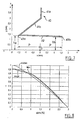
- the cover 40 also includes an oblique occultation portion 42, which extends downwardly and rearwardly from the projector, from a front edge 43b, located vertically above the point F constituting at the same time the second focal point F2 of the mirror 20 and the focus FL of the lens, and towards a rear edge 43a ("before” and “backward” are understood throughout the description with respect to the general direction of emission defined by the optical axis xx). It is thus observed that the two edges 43a, 43b are spaced along the optical axis.
- the concealment portion of the cover is a profile extending in the horizontal direction and transverse to the optical axis xx, that is to say that the edges 43a, 43b are themselves horizontal and parallel to the optical axis.
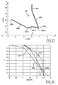
- the figure 3 illustrates, by the lines of a set of light rays R, that the two edges 43a, 43b of the occulting part 42 play two independent roles vis-à-vis the light radiation, the rear edge 43a effecting an occultation (zone shadow Z0) at a given level for the descending rays while the leading edge 43b performs ZO concealment at a determined level for the rising rays.
- This form of new cache has been designed primarily to seek a gradual attenuation of light. More precisely, knowing that there is a variety of light rays, amounts or descendants, which participate in the formation of light at a given height in the beam, such a cache allows for a gradual occultation of light, acting differently on the rising rays and on the descending rays.
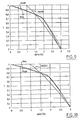
- the figure 4 drawings is a graph whose abscissa indicates the downward slope of the light (0 ° corresponding to the horizon, and the indicated values corresponding to the inclination of the light below the horizon), and of which the ordinate indicates the proportion of the light transmitted at the output of the projector (downstream of the lens 30) as a function of the aforementioned inclination, the number 1 indicating that all the light passes and the digit 0 indicating that no light passes .
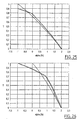
- the figure 5 illustrates a second embodiment of the invention, to reduce chromaticism especially in the lower region of the beam.
- the cache 40 of the figure 5 has a generally horizontal occulting portion 42 extending above the focus F, a first edge 43a is located rearwardly relative to said focus and a second edge 43b is located forward relative to the same focus.
- the figure 7 illustrates a third embodiment of the cache, which is different from that of the figure 5 mainly in that the cover 42 has a very slight inclination, descending forwards, relative to the horizontal plane passing through the optical axis xx.
- FIGS 9 and 10 illustrate, for their part, the attenuation behavior obtained for different settings of the caches of the figures 5 and 7 . It is observed that one can play on the angle from which the attenuation begins (here 0 °, to leave a greater amount of light in the axis of the road.
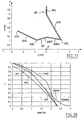
- the figure 11 illustrates a fourth embodiment of a cache according to the invention, wherein the occultation portion 42 is characterized by three useful edges 43a, 43b, 43c.
- the cover as a whole has the shape of an asymmetrical "V", with a high rear edge 43a, a low intermediate edge 43b and a high front edge 43c, these edges being interconnected in this case by portions 42a, 42b with straight cross-sections.
- the front edge 43c is here at perpendicular to the focus F, the entire occulting portion 42 extending rearwardly from this focus.
- the rear edge 43a acts on the radiation which is more downwardly inclined than the portion 42a
- the front edge 43c acts on the radiation which is more upwardly inclined than the portion 42b
- the intermediate edge 43b acts on the radiation having an intermediate inclination between these extreme inclinations.
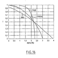
- the figure 14 illustrates a fifth embodiment of the invention, similar to that of the figure 11 but which is distinguished by the fact that the portions 42a, 42b of the cache obscuration part meet not at a sharp edge 43b, but at a smooth curve transition (zone 42c, for example section shaped arcuate).
- edges 43a, 43c play the same roles as before, but at the edge 43b is substituted for an area 42c constituting in fact an infinity of blackout edges 43b, variable according to the inclination of the neighboring light.
- the low point of the zone 42c constitutes an occulting edge vis-à-vis the radiation that propagates horizontally.
- this embodiment allows to leave a greater amount of light near the vicinity of the road axis, for a good visual comfort of the driver.
- the curved edge 43b defined by the portion 42c of the cache extends to the front free end of said cache, the portion 42b thereof does not exist in this case.
- said free end will, depending on the configurations, be operative or inoperative.
- the sixth embodiment, illustrated on the figure 17 is getting closer to that of the figure 11 in that the occulting portion 42 has three optically active sharp edges 43a, 43b and 43c, respectively.
- the essential difference lies in that the front edge 43c on the one hand is at a height close to that of the intermediate edge 43b above the optical axis xx, and on the other hand is forward with respect to the position of the focus F on said axis xx.
- the objective here is to obtain attenuation curves similar to those of figures 12 and following, but limiting or avoiding at the same time undesirable colorings of the beam in particular in its lower region.
- V shape of the portions 42b1, 42b2 which join the edges 43, 43c is here inoperative; it could for example be also a straight line, or a concavity arc of a circle facing down.
- the corresponding mitigation laws are illustrated on the figure 18 .
- a general law is observed which reinforces the light near the axis of the road, and at the same time the near laws for red, blue and green, so that the chromaticism is substantially reduced.
- the seventh embodiment illustrated on the figure 19 constitutes an intermediate achievement between that of figure 14 (rounded edge) and that of the figure 17 (overall arrangement of the edges).
- the occulting portion 42 has a rear edge 43a, a front edge 43c and a curved intermediate region 42c which defines an infinity of blackout edges 43c, according to the inclination of the light which passes in its vicinity (see above).
- the shape of the attenuation obtained is illustrated on the figure 20 , and shows an intermediate behavior between those of the caches of figures 14 and 17 .
- the figure 21 illustrates an eighth embodiment of the invention, which is similar in principle to that of the figure 17 , with a different setting.
- the attenuation achieved is practically nil down to about 1 ° below the horizon, in order to retain more light in the axis of the road, and then adopt a similar pace, in a limited angular interval, to that of the figure 18 , and this for all wavelengths so that no coloration of the beam at the beginning of the attenuation is encountered.
- the ninth embodiment of the invention illustrated on the figure 23 as for it the principle illustrated on the figure 19 an essential difference being that the portion 42b which joins the curved intermediate edge 43b and the front edge 43c is slightly inclined upwards, and shorter than in the case of the figure 19 and at the same time the portion 42a is more inclined.
- the shape of the attenuation obtained is illustrated on the figure 24 .
- the cover 40 it is possible to design the cover 40 to effect an attenuation from negative inclination values (rising light) of the light (in particular in the case where the maximum concentration of the beam in the absence of a cache is not in the the axis of the road (0 °), but slightly above it (for example, at about 1 ° above), in particular, one can parameterize the embodiment of the figure 5 in order to obtain an attenuation that begins for projected light inclination values of the order of -1 °. Examples of such attenuations are illustrated in the Figures 25 and 26 drawings.
- the corresponding figures have been indicated in millimeters.
- the attenuation curves have been modeled with the forms of caches as precisely illustrated, for an example a glass lens 30 with flat inner face and spherical outer surface, with a useful radius of the lens of 72 mm, a median draw 44 mm, a print of 44.5 mm in the red and a print of 43.5 mm in the blue.
- the various exemplary embodiments illustrated show that it is generally possible to achieve it by simply folding a thin sheet such as a steel sheet. Any other manufacturing technique and any other material can of course be considered, depending in particular on the required accuracy and resistance to the high temperature that prevails within such a projector.
- caches all having a uniform cross section along their horizontal extent transverse to the axis xx, it is of course possible to vary this section, in shape, in size, in position, etc ... as one moves along the cache horizontally and transversely to the axis xx.
Description
La présente invention concerne d'une façon générale les projecteurs du genre elliptique pour véhicules automobile, conçu pour engendrer un faisceau de route.The present invention generally relates to projectors of the elliptical genre for motor vehicles, designed to generate a driving beam.
Un projecteur du genre elliptique comprend principalement un miroir récupérateur et concentrateur du genre ellipsoïdal, possédant une première région focale dans laquelle est placée une source lumineuse, telle que le filament d'une lampe à incandescence ou l'arc d'une lampe à décharge, et une seconde région focale dans laquelle se forme une tache de concentration lumineuse après réflexion de la lumière issue de la source sur le miroir. Un tel projecteur comprend également une lentille convergente, typiquement plan-convexe, focalisée au voisinage de la seconde région focale du miroir et capable de projeter sur la route la tache lumineuse précitée.A projector of the elliptical kind mainly comprises a recuperating mirror and concentrator of the ellipsoidal kind, having a first focal region in which is placed a light source, such as the filament of an incandescent lamp or the arc of a discharge lamp, and a second focal region in which a light concentration spot is formed after reflecting light from the source onto the mirror. Such a projector also comprises a convergent lens, typically plane-convex, focused in the vicinity of the second focal region of the mirror and capable of projecting on the road the aforementioned light spot.
Un tel projecteur se prête bien à l'obtention d'un faisceau délimité par une coupure supérieure, tel qu'un faisceau de croisement. A cet effet, on prévoit au niveau de la tache lumineuse un cache de lumière destiné à occulter partiellement cette tache, de telle manière que le bord supérieur du cache définisse, dans le faisceau projeté, la coupure recherchée.Such a projector is well suited to obtaining a beam delimited by an upper cut, such as a passing beam. For this purpose, there is provided at the light spot a light cover for partially obscuring this stain, so that the upper edge of the cache defines in the projected beam, the desired cut.
On a également cherché à utiliser un tel type de projecteur pour former un faisceau de route, c'est-à-dire un faisceau présentant une pointe de concentration dans l'axe de la route, mais également une certaine largeur et une certaine épaisseur.It has also been sought to use such a type of headlight to form a driving beam, that is to say a beam having a concentration point in the axis of the road, but also a certain width and a certain thickness.
Un tel type de projecteur se prête toutefois mal à une telle application, notamment pour les raisons qui vont être données ci-dessous.Such a type of projector is however poorly suited to such an application, especially for the reasons that will be given below.
En premier lieu, du fait de la quantité de lumière importante requise dans l'axe de la route, le recours à un miroir présentant en son fond - pour le montage de la lampe - un trou de lampe de taille significative pose un problème.Firstly, because of the large amount of light required in the axis of the road, the use of a mirror having at its bottom - for mounting the lamp - a lamp hole of significant size poses a problem.
En effet la présence de ce trou de lampe se traduit dans le faisceau projeté par un défaut de lumière correspondant à l'image de ce trou de lampe, qui par nature ne récupère aucune lumière.Indeed the presence of this lamp hole is reflected in the beam projected by a defect of light corresponding to the image of this lamp hole, which by nature does not recover any light.
En fait, pour obtenir la quantité de lumière la plus importante possible dans l'axe de la route, on cherche à avoir une surface frontale de la lentille la plus importante possible par rapport à la surface du trou de lampe. Une telle démarche s'avère d'autant plus délicate que l'on cherche en général à donner à un tel projecteur un encombrement réduit en hauteur et en largeur, et donc à recourir à une lentille aussi petite que possible, ce qui est l'un des avantages les plus éminents de cette technologie de projecteur notamment en matière de style.In fact, to obtain the largest amount of light possible in the axis of the road, it is sought to have a frontal surface of the lens as large as possible relative to the surface of the lamp hole. Such an approach is all the more delicate as it is generally sought to give such a projector a reduced footprint in height and width, and therefore to use a lens as small as possible, which is the one of the most prominent advantages of this projector technology especially in terms of style.
De là, on peut donc chercher à diminuer la taille du trou de lampe, sachant qu'habituellement le montage de la lampe s'effectue au niveau du culot de celle-ci, et que ce trou de lampe présente donc une surface importante.From there, we can therefore seek to reduce the size of the lamp hole, knowing that usually the mounting of the lamp is at the base thereof, and that lamp hole thus has a large area.
Une solution pour diminuer la taille du trou de lampe consiste à monter la lampe plus en arrière, par rapport à la direction générale d'émission de la lumière, de telle sorte que seul son bulbe ait à traverser le trou de lampe, mais que le culot soit situé plus en arrière. Il en résulte que la taille de trou de lampe peut être réduite, et ce même si une distance de sécurité doit être respectée autour du bulbe de la lampe pour éviter les échauffements indésirables du miroir dans cette région.One solution for reducing the size of the lamp hole is to mount the lamp further back, relative to the general direction of light emission, so that only its bulb has to go through the lamp hole, but the base is located further back. As a result, the lamp-hole size can be reduced, even if a safety distance must be respected around the bulb of the lamp to avoid unwanted heating of the mirror in this region.
On comprend que les deux problématiques énoncées ci-dessus conduisent à recourir à une courte distance focale pour le miroir : en effet, une courte distance focale est la conséquence directe d'une part d'une minimisation de l'encombrement latéral et vertical du projecteur, et d'autre part du recul de la lampe par rapport au miroir, amenant la source lumineuse à se trouver plus en arrière dans le miroir.It will be understood that the two problems mentioned above lead to the use of a short focal distance for the mirror: in fact, a short focal distance is the direct consequence of a minimization of the lateral and vertical dimensions of the headlamp. and on the other hand the recoil of the lamp with respect to the mirror, causing the light source to be further back in the mirror.
Cette courte distance focale amène le miroir à engendrer, de par les dimensions non ponctuelles de la source (typiquement un cylindre de quelques 5 mm de long et d'environ 1 mm de diamètre) une tache de concentration lumineuse de taille importante.This short focal length causes the mirror to generate, due to the non-point dimensions of the source (typically a cylinder of some 5 mm in length and about 1 mm in diameter) a significant spot of light concentration.
Un exemple de l'allure du faisceau correspondant à la projection de cette tache sur la route est illustré sur la
On comprend qu'un tel faisceau, de par son étendue importante verticalement au-dessous de l'axe de la route, va éclairer la route à grande proximité du véhicule, jusqu'à perturber significativement le confort visuel dans le lointain.It is understood that such a beam, because of its significant extent vertically below the axis of the road, will illuminate the road close to the vehicle, to significantly disturb the visual comfort in the distance.
Une solution pour pallier cet inconvénient pourrait consister à prévoir au niveau de la tache lumineuse avant projection un cache analogue à ceux utilisés dans les projecteurs de croisement, mais dans une position retournée, de manière à occulter la lumière éclairant la route à trop grande proximité du véhicule.One solution to overcome this drawback could be to provide at the light spot before projection cache similar to those used in the crossing headlamps, but in an upside down position, so as to obscure the light illuminating the road too close to the vehicle.
Une telle solution ne serait cependant pas satisfaisante pour le confort visuel du conducteur, car elle aboutirait à un contraste très élevé au niveau d'une ligne imaginaire située sur la route en avant du véhicule. Et ce contraste s'avérerait gênant pour que le faisceau soit utilisé aussi bien en faisceau de route autonome (faisceau de croisement éteint) qu'en faisceau de route complémentant le faisceau de croisement, qui reste allumé.Such a solution would however not be satisfactory for the driver's visual comfort, since it would result in a very high contrast at the level of a imaginary line located on the road ahead of the vehicle. And this contrast would be inconvenient for the beam to be used both in autonomous beam (passing beam off) and beam complementing the beam dipped, which remains lit.
Il est par ailleurs connu du document
Ainsi la présente invention propose un projecteur du genre elliptique pour véhicule automobile selon la revendication 1.Thus, the present invention provides an elliptical projector for a motor vehicle according to
Le document de l'art antérieur
La présente invention vise à pallier ces inconvénients et limitations de l'état de la technique.The present invention aims to overcome these disadvantages and limitations of the state of the art.
Plus précisément, la présente invention vise à proposer des moyens capables d'assurer une diminution progressive de la lumière à mesure que cette lumière éclaire des zones de la route de plus en plus proches du véhicule.More specifically, the present invention aims to provide means capable of ensuring a gradual decrease in light as this light illuminates areas of the road closer and closer to the vehicle.
Un autre objet de l'invention est d'atteindre cet objectif sans donner lieu à des colorations indésirables de la lumière dues au fait que, par nature, une lentille dévie différemment le rayonnement selon la longueur d'onde de celui-ci (phénomène de chromatisme). En particulier, la présente invention vise à recourir à une occultation de la lumière qui s'effectue à distance de la surface focale de la lentille (un plan pour une lentille parfaite - mais une sorte de dôme, dont le foyer FL constitue le sommet, pour une lentille imparfaite telle que plan-sphérique). Mais elle vise en même temps à assurer que, malgré une telle défocalisation du cache, on n'assiste pas à des phénomènes de coloration indésirable du faisceau.Another object of the invention is to achieve this objective without giving rise to undesirable coloring of the light due to the fact that, by nature, a lens deviates differently the radiation according to the wavelength thereof (phenomenon of chromatism). In particular, the present invention aims at resorting to an occultation of the light which is carried out at a distance from the focal surface of the lens (a plane for a perfect lens - but a kind of dome, whose focus FL constitutes the summit, for an imperfect lens such as a spherical plane). But at the same time it aims to ensure that, despite such a defocusing of the cache, there is no witnessing phenomena of undesirable coloring of the beam.
Des aspects préférés, mais non limitatifs, du projecteur selon l'invention sont les suivants :
- lesdites régions d'occultation espacées définissent chacune un bord vif.
- lesdites régions d'occultation espacées définissent chacune un bord courbe.
- lesdites régions d'occultation espacées définissent respectivement un bord vif et un bord courbe.
- les deux bords sont à la même hauteur.
- les deux bords sont à des hauteurs différentes.
- un bord avant est situé plus bas que le bord arrière.
- l'un des bords est situé sensiblement à l'aplomb d'un foyer de la lentille.
- le bord situé sensiblement à l'aplomb du foyer de la lentille est le bord avant.
- les bords sont respectivement situés en arrière et en avant du foyer de la lentille dans la direction de l'axe optique.
- les bords sont situés sensiblement à égale distance du foyer de la lentille suivant la direction de l'axe optique.
- le cache comprend une troisième région d'occultation intermédiaire entre les première et seconde régions d'occultation.
- ladite région d'occultation intermédiaire définit un bord vif.
- ladite région d'occultation intermédiaire définit un bord arrondi.
- le bord formé par ladite troisième région d'occultation intermédiaire se trouve sensiblement à la même hauteur que l'une desdites deux régions d'occultation.
- le bord formé par ladite troisième région d'occultation intermédiaire se trouve plus bas que chacune desdites deux régions d'occultation.
- le cache s'étend dans une direction générale horizontale et transversale à l'axe optique, et présente la même section verticale sur toute son étendue.
- le cache s'étend dans une direction générale horizontale et transversale à l'axe optique, et présente une section verticale qui varie le long de son étendue.
- le cache est réalisé en tôle pliée.
- said spaced occlusion regions each define a sharp edge.
- said spaced occlusion regions each define a curved edge.
- said spaced occlusion regions respectively define a sharp edge and a curved edge.
- both edges are at the same height.
- the two edges are at different heights.
- a leading edge is located lower than the trailing edge.
- one of the edges is located substantially in line with a focus of the lens.
- the edge located substantially in line with the focus of the lens is the front edge.
- the edges are located respectively behind and in front of the focus of the lens in the direction of the optical axis.
- the edges are located substantially equidistant from the focus of the lens in the direction of the optical axis.
- the cache comprises a third occlusion region intermediate between the first and second occlusion regions.
- said intermediate occlusion region defines a sharp edge.
- said intermediate occlusion region defines a rounded edge.
- the edge formed by said third intermediate occlusion region is substantially at the same height as one of said two occultation regions.
- the edge formed by said third intermediate occlusion region is lower than each of said two occultation regions.
- the cover extends in a general direction horizontal and transverse to the optical axis, and has the same vertical section over its entire extent.
- the cover extends in a generally horizontal direction and transverse to the optical axis, and has a vertical section which varies along its extent.
- the cover is made of folded sheet.
D'autres aspects, buts et avantages de la présente invention apparaîtront mieux à la lecture de la description détaillée suivante de formes de réalisation préférées de celle-ci, donnée à titre d'exemple non limitatif et faite en référence aux dessins annexés, sur lesquels :
- la
figure 1 , déjà décrite, illustre schématiquement par un ensemble de courbes isocandela l'allure d'une tache lumineuse engendrée avec un projecteur du genre elliptique possédant un miroir ellipsoïdal à courte focale, en l'absence de tout cache, - la
figure 2 est une vue schématique en coupe verticale axiale des composants essentiels d'un projecteur du genre elliptique selon l'invention, - la
figure 3 illustre, selon une section verticale axiale du projecteur, une première forme de réalisation d'un cache du projecteur de lafigure 1 , - la
figure 4 illustre un aspect du comportement optique d'un projecteur équipé du cache de lafigure 3 , - la
figure 5 illustre une deuxième forme de réalisation d'un cache de projecteur selon l'invention, - la
figure 6 illustre un aspect du comportement optique d'un projecteur équipé du cache de lafigure 5 , - la
figure 7 illustre une troisième forme de réalisation d'un cache de projecteur selon l'invention, - la
figure 8 illustre un aspect du comportement optique d'un projecteur équipé du cache de lafigure 7 , - les
figures 9 et 10 illustrent un aspect du comportement optique d'un projecteur équipé de caches semblables à ceux desfigures 5 et7 mais de formes ou de dimensions légèrement différentes, - la
figure 11 illustre une quatrième forme de réalisation d'un cache de projecteur selon l'invention, - les
figures 12 et13 illustrent respectivement un aspect global et un aspect détaillé du comportement optique d'un projecteur équipé du cache de lafigure 11 , - la
figure 14 illustre une cinquième forme de réalisation d'un cache de projecteur selon l'invention, - les
figures 15 et16 illustrent respectivement un aspect global et un aspect détaillé du comportement optique d'un projecteur équipé du cache de lafigure 14 , - la
figure 17 illustre une sixième forme de réalisation d'un cache de projecteur selon l'invention, - la
figure 18 illustre un aspect du comportement optique d'un projecteur équipé du cache de lafigure 17 , - la
figure 19 illustre une septième forme de réalisation d'un cache de projecteur selon l'invention, - la
figure 20 illustre un aspect du comportement optique d'un projecteur équipé du cache de lafigure 19 , - la
figure 21 illustre une huitième forme de réalisation d'un cache de projecteur selon l'invention, - la
figure 22 illustre un aspect du comportement optique d'un projecteur équipé du cache de lafigure 21 , - la
figure 23 illustre une neuvième forme de réalisation d'un cache de projecteur selon l'invention, - la
figure 24 illustre un aspect du comportement optique d'un projecteur équipé du cache de lafigure 23 , et - les
figures 25 et 26 illustrent un aspect du comportement optique de projecteurs équipés de deux variantes de cache selon l'invention.
- the
figure 1 , already described, schematically illustrates by a set of curves isocandela the appearance of a light spot generated with a projector of the elliptical genre having a short-focal ellipsoidal mirror, in the absence of any cache, - the
figure 2 is a schematic view in axial vertical section of the essential components of a projector of the elliptical kind according to the invention, - the
figure 3 illustrates, according to an axial vertical section of the projector, a first embodiment of a projector cover of thefigure 1 , - the
figure 4 illustrates an aspect of the optical behavior of a projector equipped with the cache of thefigure 3 , - the
figure 5 illustrates a second embodiment of a projector cover according to the invention, - the
figure 6 illustrates an aspect of the optical behavior of a projector equipped with the cache of thefigure 5 , - the
figure 7 illustrates a third embodiment of a projector cover according to the invention, - the
figure 8 illustrates an aspect of the optical behavior of a projector equipped with the cache of thefigure 7 , - the
Figures 9 and 10 illustrate an aspect of the optical behavior of a projector equipped with caches similar to those offigures 5 and7 but of slightly different shapes or sizes, - the
figure 11 illustrates a fourth embodiment of a projector cover according to the invention, - the
figures 12 and13 illustrate respectively a global aspect and a detailed aspect of the optical behavior of a projector equipped with the cache of thefigure 11 , - the
figure 14 illustrates a fifth embodiment of a projector cover according to the invention, - the
figures 15 and16 illustrate respectively a global aspect and a detailed aspect of the optical behavior of a projector equipped with the cache of thefigure 14 , - the
figure 17 illustrates a sixth embodiment of a projector cover according to the invention, - the
figure 18 illustrates an aspect of the optical behavior of a projector equipped with the cache of thefigure 17 , - the
figure 19 illustrates a seventh embodiment of a projector cover according to the invention, - the
figure 20 illustrates an aspect of the optical behavior of a projector equipped with the cache of thefigure 19 , - the
figure 21 illustrates an eighth embodiment of a projector cover according to the invention, - the
figure 22 illustrates an aspect of the optical behavior of a projector equipped with the cache of thefigure 21 , - the
figure 23 illustrates a ninth embodiment of a projector cover according to the invention, - the
figure 24 illustrates an aspect of the optical behavior of a projector equipped with the cache of thefigure 23 , and - the
Figures 25 and 26 illustrate an aspect of the optical behavior of projectors equipped with two variants of cache according to the invention.
En référence tout d'abord à la
Cette lampe est montée dans un trou de fond 21 d'un miroir 20 du genre elliptique, tel qu'un ellipsoïde de révolution. Le filament 11 est disposé dans la première région focale F1 du miroir, de manière à former dans la seconde région focale F2 de celui-ci une tache lumineuse.This lamp is mounted in a
Le projecteur comprend également une lentille 30, ici une lentille plan-convexe, dont l'axe est confondu avec le grand axe du miroir passant par les première et seconde régions focales (cet axe, désigné par x-x, étant appelé dans la suite « l'axe optique du projecteur ») et dont le foyer FL se trouve au niveau de la seconde région focale F2 du miroir. De la sorte, la lentille 30 projette à l'infini sur la route la tache lumineuse présente dans la région F2, telle qu'on l'a décrite précédemment en référence à la
Selon l'invention, ce projecteur est équipé d'un cache spécifique 40 venant se placer au-dessus du plan horizontal passant par l'axe optique x-x et ayant pour propriété de posséder au moins deux bords actifs pour sélectivement occulter certaines composantes de la lumière provenant du miroir (contrairement aux caches classiques utilisés dans les projecteurs de croisement, qui s'étendent généralement verticalement et qui possèdent un seul bord - supérieur - optiquement actif.According to the invention, this headlamp is equipped with a
Une première forme de réalisation de ce cache est illustrée sur la
Le cache 40 comprend également une partie d'occultation oblique 42, qui s'étend vers le bas et vers l'arrière du projecteur, à partir d'un bord avant 43b, situé à l'aplomb du point F constituant en même temps le second foyer F2 du miroir 20 et le foyer FL de la lentille, et vers un bord arrière 43a (« avant » et « arrière » s'entendent tout au long de la description par rapport à la direction générale d'émission définie par l'axe optique x-x). On observe ainsi que les deux bords 43a, 43b sont espacés le long de l'axe optique.The
Dans cette forme de réalisation et avantageusement dans toutes celles qui suivent, la partie d'occultation du cache est un profilé s'étendant en direction horizontale et transversale à l'axe optique x-x, c'est-à-dire que les bords 43a, 43b sont eux mêmes horizontaux et parallèles à l'axe optique.In this embodiment and advantageously in all that follow, the concealment portion of the cover is a profile extending in the horizontal direction and transverse to the optical axis xx, that is to say that the
La
Cette forme de cache nouvelle a été conçue principalement pour rechercher une atténuation progressive de la lumière. Plus précisément, sachant qu'il existe une variété de rayons lumineux, montants ou descendants, qui participent à la formation de la lumière à une hauteur donnée dans le faisceau, un tel cache permet de réaliser une occultation progressive de la lumière, en agissant différemment sur les rayons montants et sur les rayons descendants.This form of new cache has been designed primarily to seek a gradual attenuation of light. More precisely, knowing that there is a variety of light rays, amounts or descendants, which participate in the formation of light at a given height in the beam, such a cache allows for a gradual occultation of light, acting differently on the rising rays and on the descending rays.
Ainsi la
On a ainsi tracé trois courbes (lois « alpha »), correspondant au comportement optique de l'ensemble miroir-cache-lentille pour le rouge, pour le bleu, et en médian.Three curves ("alpha" laws) have been drawn, corresponding to the optical behavior of the mirror-lens-cover assembly for the red, for the blue, and in the middle.
On observe que pour la valeur médiane, de même que pour les couleurs rouge et bleue, l'atténuation de la lumière en fonction de son inclinaison vers le bas varie de façon progressive (la courbe est oblique), ce qui est révélateur d'une coupure floue de la lumière, due à la défocalisation du cache.It is observed that for the median value, as well as for the red and blue colors, the attenuation of the light as a function of its downward inclination varies gradually (the curve is oblique), which is indicative of a blurred light, due to the defocusing of the cache.
On comprend ici que, dans la forme de réalisation de la
La
On notera à ce sujet que, lorsque les courbes d'atténuation pour les différentes couleurs (rouge et bleu dans la présente description) sont significativement écartées l'une de l'autres, elles peuvent donner lieu à une coloration du faisceau. Et autant dans l'axe de la route (0°), des différences significatives d'atténuation selon la couleur seront peu visibles par le conducteur car on éclaire alors le lointain, autant de telles différences dans la région basse du faisceau peuvent être indésirables car elles conduiront à une coloration perceptible dans la partie de faisceau éclairant la route au plus près du véhicule.It will be noted in this regard that, when the attenuation curves for the different colors (red and blue in the present description) are significantly different from one another, they may give rise to a coloration of the beam. And as much in the axis of the road (0 °), significant differences of attenuation according to the color will be little visible by the driver because one then illuminates the distance, as many such differences in the low region of the beam can be undesirable because they will lead to a perceptible coloration in the beam portion illuminating the road closer to the vehicle.
Le cache 40 de la
Pour réaliser la retenue mécanique de ce cache, on peut réaliser un montant coudé en deux parties 41a, 41b (toute autre forme inopérante sur le profil d'occultation pouvant être utilisée).To achieve the mechanical retention of this cover, it is possible to realize a bent amount in two
On a constaté que cette forme de cache limitait encore mieux les phénomènes de chromatisme.It was found that this form of cache further limited the phenomena of chromaticism.
Ainsi la
La
Le comportement correspondant en matière d'atténuation progressive est illustré sur la
Les
La
Plus précisément, le cache présente dans son ensemble la forme d'un « V » asymétrique, avec un bord arrière haut 43a, un bord intermédiaire bas 43b et un bord avant haut 43c, ces bords étant reliés entre eux en l'espèce par des portions 42a, 42b à sections transversales droites. Le bord avant 43c se trouve ici à l'aplomb du foyer F, l'ensemble de la partie d'occultation 42 s'étendant vers l'arrière à partir de ce foyer.More specifically, the cover as a whole has the shape of an asymmetrical "V", with a high
On comprend que le bord arrière 43a agit sur le rayonnement qui est plus incliné vers le bas que la portion 42a, que le bord avant 43c agit sur le rayonnement qui est plus incliné vers le haut que la portion 42b, et enfin que le bord intermédiaire 43b agit sur le rayonnement présentant une inclinaison intermédiaire entre ces inclinaisons extrêmes.It is understood that the
Cette approche permet, comme l'illustrent les
La
On comprend que les bords 43a, 43c jouent les mêmes rôles que précédemment, mais qu'au bord 43b se substitue une zone 42c constituant en réalité une infinité de bords occultants 43b, variables selon l'inclinaison de la lumière avoisinante. Notamment, le point bas de la zone 42c constitue un bord occultant vis-à-vis du rayonnement qui se propage horizontalement.It is understood that the
On comprend qu'une telle approche permet de laisser passer une quantité plus grande de lumière qui se trouve au voisinage du point F et qui se retrouvera donc au proche voisinage de l'axe de la route.It is understood that such an approach allows to pass a larger amount of light which is in the vicinity of point F and which will be found near the vicinity of the axis of the road.
Ainsi la
Ainsi cette forme de réalisation permet de laisser une quantité de lumière plus importante au proche voisinage de l'axe de la route, pour un bon confort visuel du conducteur.Thus this embodiment allows to leave a greater amount of light near the vicinity of the road axis, for a good visual comfort of the driver.
On notera ici que, selon une variante de la forme de réalisation du cache illustrée sur la
La sixième forme de réalisation, illustrée sur la
On notera ici que la forme de «V » reversé des portions 42b1, 42b2 qui réunissent les bords 43, 43c est ici inopérante ; il pourrait par exemple s'agir également d'une droite, ou d'un arc de cercle de concavité tournée vers le bas.It will be noted here that the "V" shape of the portions 42b1, 42b2 which join the
On comprend qu'un tel cache va donner lieu à un comportement intermédiaire entre celui des formes de réalisation des
Les lois d'atténuation correspondantes sont illustrées sur la
La septième forme de réalisation illustrée sur la
L'allure de l'atténuation obtenue est illustrée sur la
La
La neuvième forme de réalisation de l'invention illustrée sur la
L'allure de l'atténuation obtenue est illustrée sur la
Par ailleurs, on peut concevoir le cache 40 pour réaliser une atténuation à partir de valeurs d'inclinaison négatives (lumière montante) de la lumière (notamment dans le cas où la concentration maximale du faisceau en l'absence de cache est non pas dans l'axe de la route (0°), mais légèrement au-dessus (par exemple à environ 1° au-dessus). Notamment, on peut paramétrer la forme de réalisation de la
Pour les différents exemples de caches décrits ci-dessus, on a indiqué sur les figures correspondantes les échelles en millimètres. les courbes d'atténuation ont été modélisées avec les formes de caches telles que précisément illustrées, pour un exemple une lentille 30 en verre à face intérieure plane et à face extérieure sphérique, avec un rayon utile de la lentille de 72 mm, un tirage médian de 44 mm, un tirage de 44, 5 mm dans le rouge et un tirage de 43,5 mm dans le bleu.For the different examples of caches described above, the corresponding figures have been indicated in millimeters. the attenuation curves have been modeled with the forms of caches as precisely illustrated, for an example a
Les valeurs numériques (positions, longueurs, angles, rayons de courbure etc.) qui peuvent être lues sur ces différentes figures sont à considérer comme appartenant à la présente description.The numerical values (positions, lengths, angles, radii of curvature etc.) that can be read on these different figures are to be considered as belonging to the present description.
Naturellement, l'homme du métier saura adapter ces différentes valeurs, notamment par approches successives, pour des lentilles ayant des propriétés optiques différentes.Naturally, those skilled in the art will be able to adapt these different values, in particular by successive approaches, for lenses having different optical properties.
Pour ce qui concerne la réalisation pratique du cache, les différents exemples de réalisation illustrés montrent qu'il est en général possible de le réaliser par simple pliage d'une tôle mince telle qu'une tôle d'acier. Toute autre technique de fabrication et tout autre matériau peuvent bien entendu être envisagés, en fonction notamment de la précision requise et de la résistance à la température élevée qui règne au sein d'un tel projecteur.As regards the practical embodiment of the cover, the various exemplary embodiments illustrated show that it is generally possible to achieve it by simply folding a thin sheet such as a steel sheet. Any other manufacturing technique and any other material can of course be considered, depending in particular on the required accuracy and resistance to the high temperature that prevails within such a projector.
En outre, bien que l'on ait décrit dans ce qui précède des caches ayant tous une section transversale uniforme le long de leur étendue horizontale transversale à l'axe x-x, on peut bien entendu prévoir de faire varier cette section, en forme, en taille, en position, etc... à mesure que l'on se déplace le long du cache horizontalement et transversalement à l'axe x-x.In addition, although in the foregoing there are described caches all having a uniform cross section along their horizontal extent transverse to the axis xx, it is of course possible to vary this section, in shape, in size, in position, etc ... as one moves along the cache horizontally and transversely to the axis xx.
Claims (17)
- Headlight of the elliptical type for a motor vehicle, comprising a recuperator and concentrator mirror (20) of the ellipsoid type, with a first focal region (F1) in which a source of light (11) is placed, and a second focal region (F2) in which a light concentration spot is formed after reflection of the light obtained from the source on the mirror, and additionally comprising a converging lens (30) which is focussed in the vicinity of the second focal region of the mirror and can project the said light concentration spot onto the road, the mirror and the lens defining a optical axis (x-x) of the headlight, the said headlight additionally comprising a shield (42) which can shield part of the light which circulates between the mirror and the lens, and being disposed as a whole above the said second focal region (F2), characterised in that the shield (42) has at least two shielding regions (43a, 43b) which each define an edge, are spaced in the direction of the said optical axis, and can each shield simultaneously a specific part of the light, one (43b) of the edges is situated substantially plumb with a focal point (F) of the lens, or the edges (43a, 43b) are situated respectively to the rear and to the front of the focal point (F) of the lens, in the direction of the optical axis, the said headlight constituting an autonomous high-beam headlight or a complementary high-beam headlight of a low beam.
- Headlight according to claim 1, characterised in that the said spaced shielding regions each define a sharp edge (43a, 43b).
- Headlight according to claim 1, characterised in that the said spaced shielding regions each define a curved edge.
- Headlight according to claim 1, characterised in that the said spaced shielding regions each define a sharp edge (43a) and a curved edge (43c).
- Headlight according to one of claims 2 to 4, characterised in that the two edges (43a, 43b) are at the same height.
- Headlight according to one of claims 2 to 4, characterised in that the edges (43a, 43b) are at different heights.
- Headlight according to claim 6, characterised in that a front edge (43b) is situated lower than the rear edge (43 a).
- Headlight according to one of the preceding claims, characterised in that the edge which is situated substantially plumb with the focal point of the lens is the front edge (43b).
- Headlight according to one of the preceding claims, characterised in that the edges (43a, 43b) are situated substantially at an equal distance from the focal point (F) of the lens according to the direction of the optical axis.
- Headlight according to one of claims 2 to 9, characterised in that the shield comprises a third, intermediate shielding region (43b) between the first and second shielding regions (43a, 43c).
- Headlight according to claim 10, characterised in that the said intermediate shielding region (43b) defines a sharp edge.
- Headlight according to claim 10, characterised in that the said intermediate shielding region (43b) defines a rounded edge.
- Headlight according to one of claims 10 to 12, characterised in that the edge (43b) which is formed by the said third intermediate shielding region is substantially at the same height as one of the said two shielding regions (43a, 43c).
- Headlight according to one of claims 10 to 13, characterised in that the edge (43b) which is formed by the said third intermediate shielding region is lower than each of the said two shielding regions (43a, 43c).
- Headlight according to one of claims 1 to 14, characterised in that the shield (42) extends in a direction which is generally horizontal and transverse to the optical axis (x-x), and has the same vertical cross-section along its entire extent.
- Headlight according to one of claims 1 to 14, characterised in that shield (42) extends in a direction which is generally horizontal and transverse to the optical axis (x-x), and has a vertical cross-section which varies along its extent.
- Headlight according to one of claims 1 to 16, characterised in that the shield (42) is made of bent metal plate.
Priority Applications (1)
| Application Number | Priority Date | Filing Date | Title |
|---|---|---|---|
| DE60131600T DE60131600T3 (en) | 2000-07-07 | 2001-06-21 | Elliptical spotlight for street lighting with improved low-photometry |
Applications Claiming Priority (2)
| Application Number | Priority Date | Filing Date | Title |
|---|---|---|---|
| FR0008903A FR2811408B1 (en) | 2000-07-07 | 2000-07-07 | ELLIPTICAL PROJECTOR IN PARTICULAR FOR IMPROVED LOW PHOTOMETRY ROAD LIGHTING |
| FR0008903 | 2000-07-07 |
Publications (3)
| Publication Number | Publication Date |
|---|---|
| EP1170547A1 EP1170547A1 (en) | 2002-01-09 |
| EP1170547B1 EP1170547B1 (en) | 2007-11-28 |
| EP1170547B2 true EP1170547B2 (en) | 2011-12-14 |
Family
ID=8852252
Family Applications (1)
| Application Number | Title | Priority Date | Filing Date |
|---|---|---|---|
| EP01401648A Expired - Lifetime EP1170547B2 (en) | 2000-07-07 | 2001-06-21 | Elliptical-type headlight for road lighting with improved low photometry |
Country Status (6)
| Country | Link |
|---|---|
| US (1) | US6561688B2 (en) |
| EP (1) | EP1170547B2 (en) |
| JP (1) | JP4587608B2 (en) |
| DE (1) | DE60131600T3 (en) |
| ES (1) | ES2298205T5 (en) |
| FR (1) | FR2811408B1 (en) |
Families Citing this family (9)
| Publication number | Priority date | Publication date | Assignee | Title |
|---|---|---|---|---|
| JP4056930B2 (en) * | 2003-05-27 | 2008-03-05 | 株式会社モリタ製作所 | Medical light irradiation device |
| JP2005044574A (en) * | 2003-07-25 | 2005-02-17 | Stanley Electric Co Ltd | Lighting fixture for vehicle |
| US7036969B2 (en) * | 2003-12-04 | 2006-05-02 | Guide Corporation | Adverse weather headlamp system |
| FR2868828B1 (en) * | 2004-04-09 | 2007-03-16 | Valeo Vision Sa | LUMINOUS PROJECTOR FOR A MOTOR VEHICLE WITH A CUT-OFF BEAM, AND A CACHE ASSEMBLY FOR SUCH A PROJECTOR |
| US20060006701A1 (en) * | 2004-07-06 | 2006-01-12 | Jason Wells | System and method for rain detection and automatic operation of power roof and power windows |
| DE102005041196B4 (en) * | 2005-08-31 | 2015-05-13 | Hella Kgaa Hueck & Co. | Projection headlights for vehicles |
| JP2008276955A (en) * | 2007-04-25 | 2008-11-13 | Ichikoh Ind Ltd | Vehicle head light |
| AT516836B1 (en) | 2015-04-10 | 2016-09-15 | Zizala Lichtsysteme Gmbh | Lighting device with beam diaphragm and motor vehicle headlights |
| JP6866795B2 (en) * | 2017-07-26 | 2021-04-28 | 市光工業株式会社 | Vehicle lighting |
Citations (4)
| Publication number | Priority date | Publication date | Assignee | Title |
|---|---|---|---|---|
| DE2636137A1 (en) † | 1976-08-11 | 1978-02-16 | Thorn Electrical Ind Ltd | Colour fringing in lamps suppression method - uses mask between light source and projector lens to define cutoff in projected beam |
| EP0108915A1 (en) † | 1982-11-11 | 1984-05-23 | Westfälische Metall Industrie KG Hueck & Co. | Non-dazzling headlamp for motor vehicles |
| DE3339879C2 (en) † | 1983-11-04 | 1992-08-06 | Robert Bosch Gmbh, 7000 Stuttgart, De | |
| DE19807153A1 (en) † | 1998-02-20 | 1999-08-26 | Bosch Gmbh Robert | Headlights for vehicles according to the projection principle |
Family Cites Families (15)
| Publication number | Priority date | Publication date | Assignee | Title |
|---|---|---|---|---|
| US1614027A (en) * | 1925-07-01 | 1927-01-11 | Graf Richard | Lamp |
| FR2135432B1 (en) * | 1971-05-04 | 1973-11-30 | Laribe Armand | |
| JPH0419681Y2 (en) * | 1986-08-25 | 1992-05-06 | ||
| FR2627845B1 (en) * | 1988-02-29 | 1990-12-07 | Laribe Armand | SUPERIMPOSED ZONE CROSSING PROJECTOR |
| JPH01278848A (en) * | 1988-05-02 | 1989-11-09 | Nissan Motor Co Ltd | Headlight device for vehicle |
| JPH049683Y2 (en) * | 1988-12-16 | 1992-03-11 | ||
| JP2769259B2 (en) * | 1992-01-27 | 1998-06-25 | 株式会社小糸製作所 | Automotive headlamp |
| FR2694373B1 (en) * | 1992-07-30 | 1994-11-04 | Valeo Vision | Motor vehicle headlamp comprising a lamp with two filaments for selectively generating a fog beam and a driving beam. |
| JPH0729402A (en) * | 1993-07-12 | 1995-01-31 | Stanley Electric Co Ltd | Projection headlight |
| JP2842260B2 (en) * | 1994-01-11 | 1998-12-24 | 市光工業株式会社 | Structure to prevent color unevenness of projector type headlamp |
| US5461553A (en) * | 1994-09-28 | 1995-10-24 | Robert Bosch Gmbh | Headlight for vehicle |
| US5938323A (en) * | 1996-05-24 | 1999-08-17 | Cooper Automotive Products, Inc. | Projector light assembly |
| FR2783038B1 (en) * | 1998-09-04 | 2000-12-01 | Valeo Vision | MOTOR VEHICLE PROJECTOR WITH TRANSVERSE LAMP, EQUIPPED WITH IMPROVED LAMP MOUNTING MEANS |
| FR2788836B1 (en) * | 1999-01-26 | 2001-04-13 | Valeo Vision | MOTOR VEHICLE LIGHTING SYSTEM WITH DIURNE SIGNALING FUNCTION |
| DE19908641A1 (en) * | 1999-02-27 | 2000-08-31 | Hella Kg Hueck & Co | Headlights for vehicles |
-
2000
- 2000-07-07 FR FR0008903A patent/FR2811408B1/en not_active Expired - Lifetime
-
2001
- 2001-06-21 EP EP01401648A patent/EP1170547B2/en not_active Expired - Lifetime
- 2001-06-21 ES ES01401648T patent/ES2298205T5/en not_active Expired - Lifetime
- 2001-06-21 DE DE60131600T patent/DE60131600T3/en not_active Expired - Lifetime
- 2001-07-05 US US09/899,337 patent/US6561688B2/en not_active Expired - Lifetime
- 2001-07-09 JP JP2001207395A patent/JP4587608B2/en not_active Expired - Fee Related
Patent Citations (4)
| Publication number | Priority date | Publication date | Assignee | Title |
|---|---|---|---|---|
| DE2636137A1 (en) † | 1976-08-11 | 1978-02-16 | Thorn Electrical Ind Ltd | Colour fringing in lamps suppression method - uses mask between light source and projector lens to define cutoff in projected beam |
| EP0108915A1 (en) † | 1982-11-11 | 1984-05-23 | Westfälische Metall Industrie KG Hueck & Co. | Non-dazzling headlamp for motor vehicles |
| DE3339879C2 (en) † | 1983-11-04 | 1992-08-06 | Robert Bosch Gmbh, 7000 Stuttgart, De | |
| DE19807153A1 (en) † | 1998-02-20 | 1999-08-26 | Bosch Gmbh Robert | Headlights for vehicles according to the projection principle |
Also Published As
| Publication number | Publication date |
|---|---|
| JP4587608B2 (en) | 2010-11-24 |
| US20020003709A1 (en) | 2002-01-10 |
| DE60131600T2 (en) | 2008-10-23 |
| US6561688B2 (en) | 2003-05-13 |
| FR2811408A1 (en) | 2002-01-11 |
| JP2002063805A (en) | 2002-02-28 |
| ES2298205T3 (en) | 2008-05-16 |
| DE60131600D1 (en) | 2008-01-10 |
| EP1170547A1 (en) | 2002-01-09 |
| FR2811408B1 (en) | 2002-10-18 |
| EP1170547B1 (en) | 2007-11-28 |
| DE60131600T3 (en) | 2012-04-19 |
| ES2298205T5 (en) | 2012-03-02 |
Similar Documents
| Publication | Publication Date | Title |
|---|---|---|
| EP0439406B1 (en) | Headlight with improved light source | |
| EP0256930B1 (en) | Fog lamp with transverse filament for motor vehicles | |
| FR2863038A1 (en) | VEHICLE HEADLIGHT HAVING THREE REFLECTORS | |
| EP1170547B2 (en) | Elliptical-type headlight for road lighting with improved low photometry | |
| EP0628765B1 (en) | Vehicle headlamp with ellipsoidal type light reflector | |
| EP2867717A1 (en) | Method for defining an aspherical lens and lighting module for a motor vehicle headlight comprising such a lens | |
| EP1433999B1 (en) | Motor vehicle headlamp with a transverse light source | |
| FR2609148A1 (en) | Motor vehicle lamp comprising a reflector with complex surface and modified base | |
| EP2019258A1 (en) | Optical module with light source for automobile headlight. | |
| EP0933585B1 (en) | Vehicle headlight comprising a transversal source and able to generate a sharp dark-light cut-off | |
| FR2609146A1 (en) | Motor vehicle headlamp comprising a parabolic reflector with modified base | |
| EP0935729A1 (en) | Vehicle headlight, capable of emitting different types of beams | |
| EP1832805B1 (en) | Optical module for automobile projector fitted with an optical deviation element | |
| FR2797029A1 (en) | ELLIPTICAL PROJECTOR FOR A MOTOR VEHICLE, CAPABLE OF GENERATING A TWO-FUNCTIONAL LIGHT BEAM | |
| FR2678353A1 (en) | Headlamp with high luminous intensity and very sharp cut-off | |
| EP1538393B1 (en) | Vehicle headlight with vertical orientation | |
| EP0723109B1 (en) | Vehicle headlamp with dioptric means interposed between the light source and the reflector | |
| EP1096196A1 (en) | Headlamp for vehicle with small dimensions, in particular dipping headlamp | |
| FR2789474A1 (en) | ELLIPTICAL GENERATOR PROJECTOR FOR A MOTOR VEHICLE, CAPABLE OF SELECTIVELY ENGAGING ONE OF TWO TYPES OF BEAMS | |
| FR2597575A1 (en) | Reflector, in particular for motor vehicle lamp | |
| EP1111294A1 (en) | Vehicle headlamp with selective specialization | |
| FR2722270A1 (en) | Automobile headlight with dual reflector system | |
| EP1388463A1 (en) | Projector type headlamp capable of generating a cornering beam | |
| FR2775057A1 (en) | Automobile dipped-beam lamp with transverse light source | |
| FR2794845A1 (en) | Dual beam head lamp for motor vehicle includes reflector divided into two by wall defining two beam formats |
Legal Events
| Date | Code | Title | Description |
|---|---|---|---|
| PUAI | Public reference made under article 153(3) epc to a published international application that has entered the european phase |
Free format text: ORIGINAL CODE: 0009012 |
|
| AK | Designated contracting states |
Kind code of ref document: A1 Designated state(s): AT BE CH CY DE DK ES FI FR GB GR IE IT LI LU MC NL PT SE TR Kind code of ref document: A1 Designated state(s): DE ES GB IT |
|
| AX | Request for extension of the european patent |
Free format text: AL;LT;LV;MK;RO;SI |
|
| 17P | Request for examination filed |
Effective date: 20020123 |
|
| AKX | Designation fees paid |
Free format text: DE ES GB IT |
|
| 17Q | First examination report despatched |
Effective date: 20060807 |
|
| 17Q | First examination report despatched |
Effective date: 20060807 |
|
| GRAP | Despatch of communication of intention to grant a patent |
Free format text: ORIGINAL CODE: EPIDOSNIGR1 |
|
| GRAS | Grant fee paid |
Free format text: ORIGINAL CODE: EPIDOSNIGR3 |
|
| GRAA | (expected) grant |
Free format text: ORIGINAL CODE: 0009210 |
|
| AK | Designated contracting states |
Kind code of ref document: B1 Designated state(s): DE ES GB IT |
|
| REG | Reference to a national code |
Ref country code: GB Ref legal event code: FG4D Free format text: NOT ENGLISH |
|
| REF | Corresponds to: |
Ref document number: 60131600 Country of ref document: DE Date of ref document: 20080110 Kind code of ref document: P |
|
| REG | Reference to a national code |
Ref country code: ES Ref legal event code: FG2A Ref document number: 2298205 Country of ref document: ES Kind code of ref document: T3 |
|
| GBV | Gb: ep patent (uk) treated as always having been void in accordance with gb section 77(7)/1977 [no translation filed] | ||
| PLBI | Opposition filed |
Free format text: ORIGINAL CODE: 0009260 |
|
| PLAX | Notice of opposition and request to file observation + time limit sent |
Free format text: ORIGINAL CODE: EPIDOSNOBS2 |
|
| 26 | Opposition filed |
Opponent name: AUTOMOTIVE LIGHTING REUTLINGEN GMBH Effective date: 20080819 |
|
| PG25 | Lapsed in a contracting state [announced via postgrant information from national office to epo] |
Ref country code: GB Free format text: LAPSE BECAUSE OF FAILURE TO SUBMIT A TRANSLATION OF THE DESCRIPTION OR TO PAY THE FEE WITHIN THE PRESCRIBED TIME-LIMIT Effective date: 20071128 |
|
| PLAF | Information modified related to communication of a notice of opposition and request to file observations + time limit |
Free format text: ORIGINAL CODE: EPIDOSCOBS2 |
|
| PLBB | Reply of patent proprietor to notice(s) of opposition received |
Free format text: ORIGINAL CODE: EPIDOSNOBS3 |
|
| PUAH | Patent maintained in amended form |
Free format text: ORIGINAL CODE: 0009272 |
|
| STAA | Information on the status of an ep patent application or granted ep patent |
Free format text: STATUS: PATENT MAINTAINED AS AMENDED |
|
| 27A | Patent maintained in amended form |
Effective date: 20111214 |
|
| AK | Designated contracting states |
Kind code of ref document: B2 Designated state(s): DE ES GB IT |
|
| REG | Reference to a national code |
Ref country code: DE Ref legal event code: R102 Ref document number: 60131600 Country of ref document: DE |
|
| REG | Reference to a national code |
Ref country code: DE Ref legal event code: R102 Ref document number: 60131600 Country of ref document: DE Effective date: 20111214 |
|
| REG | Reference to a national code |
Ref country code: ES Ref legal event code: DC2A Ref document number: 2298205 Country of ref document: ES Kind code of ref document: T5 Effective date: 20120302 |
|
| PGFP | Annual fee paid to national office [announced via postgrant information from national office to epo] |
Ref country code: DE Payment date: 20170614 Year of fee payment: 17 |
|
| PGFP | Annual fee paid to national office [announced via postgrant information from national office to epo] |
Ref country code: IT Payment date: 20170619 Year of fee payment: 17 |
|
| PGFP | Annual fee paid to national office [announced via postgrant information from national office to epo] |
Ref country code: ES Payment date: 20170707 Year of fee payment: 17 |
|
| REG | Reference to a national code |
Ref country code: DE Ref legal event code: R079 Ref document number: 60131600 Country of ref document: DE Free format text: PREVIOUS MAIN CLASS: F21S0008120000 Ipc: F21S0041000000 |
|
| REG | Reference to a national code |
Ref country code: DE Ref legal event code: R119 Ref document number: 60131600 Country of ref document: DE |
|
| PG25 | Lapsed in a contracting state [announced via postgrant information from national office to epo] |
Ref country code: IT Free format text: LAPSE BECAUSE OF NON-PAYMENT OF DUE FEES Effective date: 20180621 Ref country code: DE Free format text: LAPSE BECAUSE OF NON-PAYMENT OF DUE FEES Effective date: 20190101 |
|
| REG | Reference to a national code |
Ref country code: ES Ref legal event code: FD2A Effective date: 20190916 |
|
| PG25 | Lapsed in a contracting state [announced via postgrant information from national office to epo] |
Ref country code: ES Free format text: LAPSE BECAUSE OF NON-PAYMENT OF DUE FEES Effective date: 20180622 |