EP1564384A1 - Elektrisch gesteuertes, in einem Schalldämpfer integriertes Ventil verwendet bei einer Zylinderdeaktivierung - Google Patents
Elektrisch gesteuertes, in einem Schalldämpfer integriertes Ventil verwendet bei einer Zylinderdeaktivierung Download PDFInfo
- Publication number
- EP1564384A1 EP1564384A1 EP05250283A EP05250283A EP1564384A1 EP 1564384 A1 EP1564384 A1 EP 1564384A1 EP 05250283 A EP05250283 A EP 05250283A EP 05250283 A EP05250283 A EP 05250283A EP 1564384 A1 EP1564384 A1 EP 1564384A1
- Authority
- EP
- European Patent Office
- Prior art keywords
- valve
- exhaust
- multiple positions
- actuator
- electrical actuator
- Prior art date
- Legal status (The legal status is an assumption and is not a legal conclusion. Google has not performed a legal analysis and makes no representation as to the accuracy of the status listed.)
- Granted
Links
Images
Classifications
-
- F—MECHANICAL ENGINEERING; LIGHTING; HEATING; WEAPONS; BLASTING
- F01—MACHINES OR ENGINES IN GENERAL; ENGINE PLANTS IN GENERAL; STEAM ENGINES
- F01N—GAS-FLOW SILENCERS OR EXHAUST APPARATUS FOR MACHINES OR ENGINES IN GENERAL; GAS-FLOW SILENCERS OR EXHAUST APPARATUS FOR INTERNAL-COMBUSTION ENGINES
- F01N1/00—Silencing apparatus characterised by method of silencing
- F01N1/16—Silencing apparatus characterised by method of silencing by using movable parts
- F01N1/166—Silencing apparatus characterised by method of silencing by using movable parts for changing the flow path through the silencer or for adjusting the dimensions of a chamber or a pipe
-
- F—MECHANICAL ENGINEERING; LIGHTING; HEATING; WEAPONS; BLASTING
- F01—MACHINES OR ENGINES IN GENERAL; ENGINE PLANTS IN GENERAL; STEAM ENGINES
- F01N—GAS-FLOW SILENCERS OR EXHAUST APPARATUS FOR MACHINES OR ENGINES IN GENERAL; GAS-FLOW SILENCERS OR EXHAUST APPARATUS FOR INTERNAL-COMBUSTION ENGINES
- F01N1/00—Silencing apparatus characterised by method of silencing
- F01N1/16—Silencing apparatus characterised by method of silencing by using movable parts
- F01N1/161—Silencing apparatus characterised by method of silencing by using movable parts for adjusting resonance or dead chambers or passages to resonance or dead chambers
- F01N1/163—Silencing apparatus characterised by method of silencing by using movable parts for adjusting resonance or dead chambers or passages to resonance or dead chambers by means of valves
-
- F—MECHANICAL ENGINEERING; LIGHTING; HEATING; WEAPONS; BLASTING
- F01—MACHINES OR ENGINES IN GENERAL; ENGINE PLANTS IN GENERAL; STEAM ENGINES
- F01N—GAS-FLOW SILENCERS OR EXHAUST APPARATUS FOR MACHINES OR ENGINES IN GENERAL; GAS-FLOW SILENCERS OR EXHAUST APPARATUS FOR INTERNAL-COMBUSTION ENGINES
- F01N13/00—Exhaust or silencing apparatus characterised by constructional features
- F01N13/14—Exhaust or silencing apparatus characterised by constructional features having thermal insulation
-
- F—MECHANICAL ENGINEERING; LIGHTING; HEATING; WEAPONS; BLASTING
- F01—MACHINES OR ENGINES IN GENERAL; ENGINE PLANTS IN GENERAL; STEAM ENGINES
- F01N—GAS-FLOW SILENCERS OR EXHAUST APPARATUS FOR MACHINES OR ENGINES IN GENERAL; GAS-FLOW SILENCERS OR EXHAUST APPARATUS FOR INTERNAL-COMBUSTION ENGINES
- F01N13/00—Exhaust or silencing apparatus characterised by constructional features
- F01N13/18—Construction facilitating manufacture, assembly, or disassembly
- F01N13/1805—Fixing exhaust manifolds, exhaust pipes or pipe sections to each other, to engine or to vehicle body
-
- F—MECHANICAL ENGINEERING; LIGHTING; HEATING; WEAPONS; BLASTING
- F01—MACHINES OR ENGINES IN GENERAL; ENGINE PLANTS IN GENERAL; STEAM ENGINES
- F01N—GAS-FLOW SILENCERS OR EXHAUST APPARATUS FOR MACHINES OR ENGINES IN GENERAL; GAS-FLOW SILENCERS OR EXHAUST APPARATUS FOR INTERNAL-COMBUSTION ENGINES
- F01N13/00—Exhaust or silencing apparatus characterised by constructional features
- F01N13/18—Construction facilitating manufacture, assembly, or disassembly
- F01N13/1838—Construction facilitating manufacture, assembly, or disassembly characterised by the type of connection between parts of exhaust or silencing apparatus, e.g. between housing and tubes, between tubes and baffles
- F01N13/1844—Mechanical joints
-
- F—MECHANICAL ENGINEERING; LIGHTING; HEATING; WEAPONS; BLASTING
- F02—COMBUSTION ENGINES; HOT-GAS OR COMBUSTION-PRODUCT ENGINE PLANTS
- F02D—CONTROLLING COMBUSTION ENGINES
- F02D17/00—Controlling engines by cutting out individual cylinders; Rendering engines inoperative or idling
- F02D17/02—Cutting-out
-
- F—MECHANICAL ENGINEERING; LIGHTING; HEATING; WEAPONS; BLASTING
- F02—COMBUSTION ENGINES; HOT-GAS OR COMBUSTION-PRODUCT ENGINE PLANTS
- F02D—CONTROLLING COMBUSTION ENGINES
- F02D9/00—Controlling engines by throttling air or fuel-and-air induction conduits or exhaust conduits
- F02D9/04—Controlling engines by throttling air or fuel-and-air induction conduits or exhaust conduits concerning exhaust conduits
Definitions
- This invention relates to an exhaust system having a valve for reducing noise, vibration and harshness (NVH).
- the invention relates to an electrically controlled in-muffler exhaust valve for displacement on demand internal combustion engines.
- V-8 operates in V-8 mode when the vehicle requires more power such as towing a trailer.
- the powertrain control system deactivates four of the cylinders so that the engine operates in V-4 mode when the vehicle requires less power such as when it is lightly loaded and cruising at highway speeds.
- One prior solution utilizes a cast iron housing arranged between the muffler and catalytic converter.
- a valve arranged in the cast iron housing is actuated by a vacuum actuator.
- Vacuum hoses must be routed a considerable length from the engine to the exhaust system to operate the vacuum actuator.
- the cast housing has considerable weight and presents reliability issues and increased assembly attributable to the connections between the cast housing and the adjacent exhaust system components.
- the vacuum actuator presents reliability issues resulting from the considerable length the vacuum hoses and connections, which may be damaged during off road vehicle use or assembly at the vehicle assembly plant.
- the actuator since the actuator is vacuum operated, limited control over the valve is possible since its operation is based upon engine manifold pressure.
- the vacuum actuator lacks safeguards in the event of an actuator or valve malfunction.
- the invention provides a powertrain control system including an engine having multiple cylinders.
- a controller selectively activates the cylinders to provide a cylinder combination having a desired power displacement.
- the controller selectively activates the cylinders between a V-8 and V-4 mode.
- An exhaust system having a valve and an electrical actuator selectively electrically actuates the valve in response to the controller between multiple positions.
- the electrical actuator moves the valve from an open position in V-8 mode to a partially closed position in V-4 mode to increase back pressure and reduce NVH issues in V-4 mode.
- a muffler in an example exhaust system, includes a housing having an exhaust passage.
- the valve is supported by the housing and arranged in the exhaust passage.
- the valve is moveable between multiple positions for tuning the muffler.
- the electrical actuator is supported by the housing to actuate the valve between the multiple positions.
- the actuator is supported by an actuator mounting pipe arranged exterior of the main housing portion to remove it from the high temperatures found within the main housing portion.
- the actuator is further insulated by using one or more heat shields between the actuator and portions of the housing.
- a return spring moves the valve to an open position in the event of a system malfunction.
- a position sensor detects the position of the valve to ensure that the valve is operating as desired and to coordinate the valve operation with other aspects of the powertrain control system.
- the present invention provides an improved powertrain system providing variable tuning in displacement on demand engine configurations.
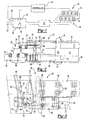
- a powertrain control system 10 is shown in Figure 1.
- the system 10 includes an internal combustion engine 12 having multiple cylinders 14.
- V-8 mode both cylinders A and B are activated, for example by supply fuel to all cylinders, so that all eight cylinders provide power to the vehicle.
- V-4 mode only cylinders A are activated so that only four cylinders provide power to the vehicle, for example by cutting fuel to cylinders B, thereby reducing fuel consumption and increasing fuel economy during vehicle operating conditions in which reduced engine power is not noticeable to the vehicle operator.
- V-8 and V-4 modes other engine configurations having other displacement configurations and modes may also be used with this invention.
- the system 10 includes an exhaust system 17 receiving exhaust gases from the cylinders 14.
- the exhaust system 17 includes exhaust manifolds 16 that carry the exhaust gases to a catalytic converter 18.
- the exhaust gases flow from the catalytic converter to a muffler 20 tuned to reduce NVH issues, and the exhaust gases are expelled from a tailpipe 22.
- the muffler 20 includes internal structure that provides tuning to reduce the NVH issues for the engine 12.
- the structural features of the muffler 20 can only be tuned for one of the modes.
- the muffler 20 is tuned for V-8 mode.
- undesirable NVH may result when engine 12 is operating in V-4 mode, which may manifest itself as a tinny or hollow sound.
- the undesirable NVH issues may be addressed by partially blocking the exhaust flow to increase the back pressure and reflect sound wave energy upstream in the exhaust system 17 to reduce low frequency noise levels in V-4 operation.
- Secondary mufflers or passive resonators typically found in intake systems are impractical for exhaust systems due to size and packaging considerations.
- adding additional components and structure exterior to the exhaust system components typically found within a powertrain system is undesirable to due size, weight, and reliability considerations.
- the inventive powertrain control system 10 incorporates an electrical actuator 26 that operates a valve 28 moving it between multiple positions. Both the actuator 26 and valve 28 are preferably supported by the muffler 20 using many structural components typical to a muffler. Using an electrical actuator enables the valve 28 to be operated at any time and enables the wires to be routed where they are less likely to become damaged.
- a controller 24 is connected to the actuator 26 and engine 12 to coordinate the operation of the valve 28 as the engine 12 switches between V-8 and V-4 modes.
- a position sensor 70 is also supported by the muffler 20 in one example and connected to the controller 24 to detect the position of the valve 28 and ensure desired operation of the actuator 26 and valve 28.
- the inventive muffler 20 includes a housing 30 having a main housing portion provided an outer shell 32.
- the main housing portion is the large body where the exhaust is tuned.
- the main housing portion is approximately the same size as a conventional muffler to avoid packaging issues.
- Baffles 34 are arranged interiorly of the outer shell 32 to support the outer shell 32 and provide support structure for components within the muffler 20.
- the baffles 34 also provide resonant chambers and fluid connections between components within the muffler 20, as is well known in the art.
- End caps 35 are arranged at either end of the muffler to conceal the muffler 20 to enclose the components within.
- An inlet pipe 36 is supported by an end cap 35 and carries exhaust gases from the engine 12 to the interior of the muffler 20 for tuning.
- the exhaust gases from the engine within the inlet pipe 36 are at a considerably high temperature that would melt insulation on the wire windings of an electric actuator.
- the exhaust gas flows along an exhaust passageway provided by the inlet pipe 36 and inner pipe 38 arranged within the housing 30.
- a valve body 64 is arranged between the inlet pipe 36 and inner pipe 38 and provides a portion of the exhaust passage.
- the valve 28 does not divert exhaust gases to other passages, but rather selectively provides a variable restriction.
- the exhaust gas flows from the exhaust passage out the inner pipe 38 to a first chamber 40, which is in fluid communication with a second chamber 42 that acts as a Helmholtz resonator.
- a passage 44 is arranged in a baffle 34 to permit pressure waves to travel between the first 40 and second 42 chambers.
- Exhaust gas flows from the first chamber to an outlet pipe 46 which may include curves for tuning and packaging within the muffler 20.
- the inlet pipe 36, inner pipe 38, and outlet pipe 46 are supported by the baffles 34.
- An actuator mounting pipe 48 is supported by an end cap 35 approximate to the inlet pipe 36.
- the actuator mounting pipe 48 includes a portion that extends exterior of the housing 30 to reduce the temperature to which the actuator mounting pipe is exposed.
- a plate 50 is supported on the actuator mounting pipe 48 and supports the electrical actuator 26.
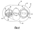
- One or more heat shields 76 are arranged between the electrical actuator 26 and the inlet pipe 36 to reduce the temperature to which the wire windings of the electrical actuator 26 are exposed.
- one suitable electrical actuator has a temperature limit of approximately 120° C, which makes insulation desirable.
- a vacuum actuator has a temperature limit of approximately 200° C.
- the heat shields 76 include protrusions 78, best seen in Figure 4, used to space the surface of the heat shields 76 from the inlet pipe 36 and actuator mounting pipe 48 to provide improved insulation.
- the heat shields 76 are secured to the inlet pipe 36 and actuator mounting pipe 48 by band clamps 80.
- the electrical actuator 26 moves a rod 54 in a generally linear direction.
- a clevis 56 at an end of the rod 54 is secured to an arm 58 mounted on a shaft 60.
- the valve 28 is secured to the shaft 60 with the valve 28 arranged within the valve body 64.
- the shaft 60 is supported by wire mesh bearings 66.
- One bearing is mounted on the valve body 64 for supporting one end of the shaft 60, and another bearing 66 is mounted on a portion of the actuator mounting pipe 48 that extends into the housing 30.
- the actuator mounting pipe 48 is sealed off from the hot exhaust gases.
- a stop 68 is supported by the actuator mounting pipe 48 to limit the travel of the valve 28.
- the stop 68 in the example shown, defines the open position used when operating in V-8 mode.
- a return spring 72 is schematically shown arranged internal to the electrical actuator 26, for a type of actuator well known in the art, to bias the valve 28 to the open position. Specifically, the return spring 72 urges the arm 58 against the stop 68 in the event of an actuator/valve malfunction, for example, in the event the actuator 26 loses power.
- the baffles 34, actuator mounting pipe 48, and valve body 64 include locating features 74, for example similar to those found in U.S. Patent No. 5,290,974, for ensuring that the actuator mounting pipe 48 and valve body 64 are oriented in a desired position relative to one another for improved assembly and operation of the muffler 20.
- the position sensor 70 is supported by the muffler 20 and, in the example shown, is located within the housing 30 to detect the position of the valve 28. In one example, the position sensor 70 is located proximate to the arm 58 to detect the rotational position of the shaft 60.
- the position sensor 70 is electrically connected to the controller 24 and the sensor's 70 output is monitored to ensure desired operation of the powertrain control system. For example, if the valve 28 should become stuck or otherwise located in a position other than desired, the controller will command other powertrain controls to ensure the most desirable operation of the powertrain control system.
Landscapes
- Engineering & Computer Science (AREA)
- Chemical & Material Sciences (AREA)
- Combustion & Propulsion (AREA)
- Mechanical Engineering (AREA)
- General Engineering & Computer Science (AREA)
- Exhaust Silencers (AREA)
- Output Control And Ontrol Of Special Type Engine (AREA)
- Valve Device For Special Equipments (AREA)
Applications Claiming Priority (2)
| Application Number | Priority Date | Filing Date | Title |
|---|---|---|---|
| US10/777,394 US7428947B2 (en) | 2004-02-12 | 2004-02-12 | Electrically controlled in-muffler exhaust valve for use during cylinder deactivation |
| US777394 | 2004-02-12 |
Publications (2)
| Publication Number | Publication Date |
|---|---|
| EP1564384A1 true EP1564384A1 (de) | 2005-08-17 |
| EP1564384B1 EP1564384B1 (de) | 2008-08-20 |
Family
ID=34701377
Family Applications (1)
| Application Number | Title | Priority Date | Filing Date |
|---|---|---|---|
| EP05250283A Expired - Lifetime EP1564384B1 (de) | 2004-02-12 | 2005-01-20 | Elektrisch gesteuertes, in einem Schalldämpfer integriertes Ventil verwendet bei einer Zylinderdeaktivierung |
Country Status (5)
| Country | Link |
|---|---|
| US (1) | US7428947B2 (de) |
| EP (1) | EP1564384B1 (de) |
| AT (1) | ATE405731T1 (de) |
| DE (1) | DE602005009047D1 (de) |
| ES (1) | ES2313233T3 (de) |
Cited By (1)
| Publication number | Priority date | Publication date | Assignee | Title |
|---|---|---|---|---|
| AT507516B1 (de) * | 2010-02-04 | 2011-07-15 | Avl List Gmbh | Brennkraftmaschine mit zylinderabschaltung |
Families Citing this family (16)
| Publication number | Priority date | Publication date | Assignee | Title |
|---|---|---|---|---|
| US20050155816A1 (en) * | 2004-01-16 | 2005-07-21 | Alcini William V. | Dynamic exhaust system for advanced internal combustion engines |
| US20070163243A1 (en) * | 2006-01-17 | 2007-07-19 | Arvin Technologies, Inc. | Exhaust system with cam-operated valve assembly and associated method |
| US9376947B2 (en) | 2007-03-29 | 2016-06-28 | Faurecia Emissions Control Technologies Usa, Llc | Hybrid valve for attenuation of low frequency noise |
| JP2008274893A (ja) * | 2007-05-07 | 2008-11-13 | Mikuni Corp | 排気バルブ装置 |
| DE112011103989T5 (de) | 2010-12-01 | 2013-08-29 | Faurecia Emissions Control Technologies, Usa, Llc | Auslassventil in Kombination mit einem aktiven Geräuschdämpfungssystem |
| DE102010064088A1 (de) | 2010-12-02 | 2012-06-06 | Kess-Tech Gmbh | Schalldämpfer für Auspuff-Anlagen |
| US9540995B2 (en) | 2012-03-06 | 2017-01-10 | KATCON USA, Inc. | Exhaust valve assembly |
| US10400691B2 (en) | 2013-10-09 | 2019-09-03 | Tula Technology, Inc. | Noise/vibration reduction control |
| WO2015054412A1 (en) * | 2013-10-09 | 2015-04-16 | Tula Technology, Inc. | Noise/vibration reduction control |
| US9388718B2 (en) | 2014-03-27 | 2016-07-12 | Ge Oil & Gas Compression Systems, Llc | System and method for tuned exhaust |
| US9500113B2 (en) | 2014-03-28 | 2016-11-22 | Honda Motor Co., Ltd. | Aftermarket exhaust detection |
| US10001191B2 (en) | 2015-01-16 | 2018-06-19 | Ford Global Technologies, Llc | Pneumatically tuned vehicle powertrain mounts |
| US10823023B2 (en) * | 2017-12-27 | 2020-11-03 | Randy Phelps | Selective acoustic soundproofing device |
| US10493836B2 (en) | 2018-02-12 | 2019-12-03 | Tula Technology, Inc. | Noise/vibration control using variable spring absorber |
| US11326490B2 (en) | 2018-05-02 | 2022-05-10 | Faurecia Emissions Control Technologies, Usa, Llc | Variable restriction valve for vehicle exhaust system |
| US11149602B2 (en) | 2018-05-22 | 2021-10-19 | Faurecia Emissions Control Technologies, Usa, Llc | Passive flap valve for vehicle exhaust system |
Citations (7)
| Publication number | Priority date | Publication date | Assignee | Title |
|---|---|---|---|---|
| US4866933A (en) * | 1988-09-21 | 1989-09-19 | Whau Chih Kao | Exhaust silencer |
| US5388408A (en) * | 1993-10-01 | 1995-02-14 | Lawrence-Keech Inc. | Exhaust system for internal combustion engines |
| US5582004A (en) * | 1994-09-01 | 1996-12-10 | Dr. Ing. H.C.F. Porsche Ag | Exhaust system for a multi-cylinder internal combustion engine |
| JPH0979023A (ja) * | 1995-09-13 | 1997-03-25 | Calsonic Corp | バルブ内蔵制御型排気マフラ |
| US5739483A (en) * | 1994-05-09 | 1998-04-14 | Nissan Motor Co., Ltd. | Automobile exhaust noise suppressor |
| EP1036919A2 (de) * | 1999-03-15 | 2000-09-20 | Volkswagen Aktiengesellschaft | Brennkraftmaschine mit einer Abgasregelvorrichtung |
| JP2003161149A (ja) * | 2001-11-26 | 2003-06-06 | Suzuki Motor Corp | 小型車両のエンジン排気装置 |
Family Cites Families (6)
| Publication number | Priority date | Publication date | Assignee | Title |
|---|---|---|---|---|
| JPS61112713A (ja) | 1984-11-05 | 1986-05-30 | Kawasaki Heavy Ind Ltd | 排気装置 |
| JP2723948B2 (ja) * | 1988-02-18 | 1998-03-09 | マツダ株式会社 | エンジンの制御装置 |
| FR2693505B1 (fr) * | 1992-07-07 | 1994-09-09 | Centre Ntl Recherche Scient | Ligne d'admission ou d'échappement pour machine alternative. |
| US5290974A (en) * | 1993-03-12 | 1994-03-01 | Arvin Industries, Inc. | Tab and notch locator for exhaust systems |
| WO1997040264A1 (en) * | 1996-04-22 | 1997-10-30 | Meusen Wilhelmus Lambertus Arn | Exhaust assembly for use with combustion engines, and vehicle provided with such assembly |
| US6662554B2 (en) * | 2002-01-23 | 2003-12-16 | Deere & Company | Adjustable restriction muffler system for a combine |
-
2004
- 2004-02-12 US US10/777,394 patent/US7428947B2/en not_active Expired - Lifetime
-
2005
- 2005-01-20 DE DE602005009047T patent/DE602005009047D1/de not_active Expired - Lifetime
- 2005-01-20 AT AT05250283T patent/ATE405731T1/de not_active IP Right Cessation
- 2005-01-20 EP EP05250283A patent/EP1564384B1/de not_active Expired - Lifetime
- 2005-01-20 ES ES05250283T patent/ES2313233T3/es not_active Expired - Lifetime
Patent Citations (7)
| Publication number | Priority date | Publication date | Assignee | Title |
|---|---|---|---|---|
| US4866933A (en) * | 1988-09-21 | 1989-09-19 | Whau Chih Kao | Exhaust silencer |
| US5388408A (en) * | 1993-10-01 | 1995-02-14 | Lawrence-Keech Inc. | Exhaust system for internal combustion engines |
| US5739483A (en) * | 1994-05-09 | 1998-04-14 | Nissan Motor Co., Ltd. | Automobile exhaust noise suppressor |
| US5582004A (en) * | 1994-09-01 | 1996-12-10 | Dr. Ing. H.C.F. Porsche Ag | Exhaust system for a multi-cylinder internal combustion engine |
| JPH0979023A (ja) * | 1995-09-13 | 1997-03-25 | Calsonic Corp | バルブ内蔵制御型排気マフラ |
| EP1036919A2 (de) * | 1999-03-15 | 2000-09-20 | Volkswagen Aktiengesellschaft | Brennkraftmaschine mit einer Abgasregelvorrichtung |
| JP2003161149A (ja) * | 2001-11-26 | 2003-06-06 | Suzuki Motor Corp | 小型車両のエンジン排気装置 |
Non-Patent Citations (2)
| Title |
|---|
| PATENT ABSTRACTS OF JAPAN vol. 1997, no. 07 31 July 1997 (1997-07-31) * |
| PATENT ABSTRACTS OF JAPAN vol. 2003, no. 10 8 October 2003 (2003-10-08) * |
Cited By (2)
| Publication number | Priority date | Publication date | Assignee | Title |
|---|---|---|---|---|
| AT507516B1 (de) * | 2010-02-04 | 2011-07-15 | Avl List Gmbh | Brennkraftmaschine mit zylinderabschaltung |
| WO2011095390A1 (de) | 2010-02-04 | 2011-08-11 | Avl List Gmbh | Brennkraftmaschine mit zylinderabschaltung |
Also Published As
| Publication number | Publication date |
|---|---|
| US20050178612A1 (en) | 2005-08-18 |
| US7428947B2 (en) | 2008-09-30 |
| ES2313233T3 (es) | 2009-03-01 |
| DE602005009047D1 (de) | 2008-10-02 |
| ATE405731T1 (de) | 2008-09-15 |
| EP1564384B1 (de) | 2008-08-20 |
Similar Documents
| Publication | Publication Date | Title |
|---|---|---|
| US7428947B2 (en) | Electrically controlled in-muffler exhaust valve for use during cylinder deactivation | |
| US6755279B2 (en) | Controllable muffler system for internal combustion engine | |
| JP4486963B2 (ja) | 内燃機関の排気装置 | |
| KR100369212B1 (ko) | 내연 기관의 배기 소음 및/또는 기체 이송 시스템의 덕트내부의 소음을 제어하기 위한 장치 및 방법 | |
| EP3392479B1 (de) | Strassenfahrzeug mit einem verbrennungsmotor und mit einer vorrichtung für die übertragung von abgasgeräusch | |
| US8220264B2 (en) | Integrated inboard exhaust manifolds for V-type engines | |
| US9109483B2 (en) | Exhaust system for an internal combustion engine | |
| US20130037005A1 (en) | Internal combustion engine haivng cylinder deactivation | |
| CN201835911U (zh) | 具有增压空气冷却器的内燃发动机 | |
| US8689934B2 (en) | Sound absorbing structure | |
| US20050109024A1 (en) | Electrically controlled exhaust valve | |
| JP2011174425A (ja) | 内燃機関の多段過給装置 | |
| US7434390B2 (en) | Air-gap-insulated exhaust manifold | |
| CN101326068A (zh) | 具有涡轮增压器的内燃机 | |
| JPS6321329A (ja) | エンジンの排気装置 | |
| JP3846581B2 (ja) | 吸気モジュール | |
| KR100372706B1 (ko) | 자동차용 배기 시스템의 소음기 | |
| JPH0577531U (ja) | ターボ過給機付エンジンの排気装置 | |
| JP2008095527A (ja) | 内燃機関の排気装置 | |
| JP3212118B2 (ja) | エンジンの排気装置 | |
| JPH116416A (ja) | 自動車用排気消音装置 | |
| JP2004196146A (ja) | 車両用の熱交換器 | |
| KR20130000176A (ko) | 차량용 배기 매니폴드 유닛 | |
| JP2025047187A (ja) | 車両の排気システム | |
| KR20120019956A (ko) | 배기 집합부와 실린더 헤드가 일체형으로 형성된 엔진 |
Legal Events
| Date | Code | Title | Description |
|---|---|---|---|
| PUAI | Public reference made under article 153(3) epc to a published international application that has entered the european phase |
Free format text: ORIGINAL CODE: 0009012 |
|
| AK | Designated contracting states |
Kind code of ref document: A1 Designated state(s): AT BE BG CH CY CZ DE DK EE ES FI FR GB GR HU IE IS IT LI LT LU MC NL PL PT RO SE SI SK TR |
|
| AX | Request for extension of the european patent |
Extension state: AL BA HR LV MK YU |
|
| 17P | Request for examination filed |
Effective date: 20050805 |
|
| AKX | Designation fees paid |
Designated state(s): AT BE BG CH CY CZ DE DK EE ES FI FR GB GR HU IE IS IT LI LT LU MC NL PL PT RO SE SI SK TR |
|
| 17Q | First examination report despatched |
Effective date: 20060317 |
|
| RAP1 | Party data changed (applicant data changed or rights of an application transferred) |
Owner name: ET US HOLDINGS LLC |
|
| RAP1 | Party data changed (applicant data changed or rights of an application transferred) |
Owner name: EMCON TECHNOLOGIES LLC |
|
| GRAP | Despatch of communication of intention to grant a patent |
Free format text: ORIGINAL CODE: EPIDOSNIGR1 |
|
| RAP1 | Party data changed (applicant data changed or rights of an application transferred) |
Owner name: EMCON TECHNOLOGIES LLC |
|
| RIN1 | Information on inventor provided before grant (corrected) |
Inventor name: WOERNER, DAVID Inventor name: CALLAHAN, JOSEPH Inventor name: NOHL, JOHN |
|
| GRAS | Grant fee paid |
Free format text: ORIGINAL CODE: EPIDOSNIGR3 |
|
| GRAA | (expected) grant |
Free format text: ORIGINAL CODE: 0009210 |
|
| AK | Designated contracting states |
Kind code of ref document: B1 Designated state(s): AT BE BG CH CY CZ DE DK EE ES FI FR GB GR HU IE IS IT LI LT LU MC NL PL PT RO SE SI SK TR |
|
| REG | Reference to a national code |
Ref country code: GB Ref legal event code: FG4D |
|
| REG | Reference to a national code |
Ref country code: CH Ref legal event code: EP |
|
| REG | Reference to a national code |
Ref country code: IE Ref legal event code: FG4D |
|
| REF | Corresponds to: |
Ref document number: 602005009047 Country of ref document: DE Date of ref document: 20081002 Kind code of ref document: P |
|
| PG25 | Lapsed in a contracting state [announced via postgrant information from national office to epo] |
Ref country code: LT Free format text: LAPSE BECAUSE OF FAILURE TO SUBMIT A TRANSLATION OF THE DESCRIPTION OR TO PAY THE FEE WITHIN THE PRESCRIBED TIME-LIMIT Effective date: 20080820 Ref country code: IS Free format text: LAPSE BECAUSE OF FAILURE TO SUBMIT A TRANSLATION OF THE DESCRIPTION OR TO PAY THE FEE WITHIN THE PRESCRIBED TIME-LIMIT Effective date: 20081220 Ref country code: NL Free format text: LAPSE BECAUSE OF FAILURE TO SUBMIT A TRANSLATION OF THE DESCRIPTION OR TO PAY THE FEE WITHIN THE PRESCRIBED TIME-LIMIT Effective date: 20080820 |
|
| PG25 | Lapsed in a contracting state [announced via postgrant information from national office to epo] |
Ref country code: AT Free format text: LAPSE BECAUSE OF FAILURE TO SUBMIT A TRANSLATION OF THE DESCRIPTION OR TO PAY THE FEE WITHIN THE PRESCRIBED TIME-LIMIT Effective date: 20080820 Ref country code: FI Free format text: LAPSE BECAUSE OF FAILURE TO SUBMIT A TRANSLATION OF THE DESCRIPTION OR TO PAY THE FEE WITHIN THE PRESCRIBED TIME-LIMIT Effective date: 20080820 Ref country code: SI Free format text: LAPSE BECAUSE OF FAILURE TO SUBMIT A TRANSLATION OF THE DESCRIPTION OR TO PAY THE FEE WITHIN THE PRESCRIBED TIME-LIMIT Effective date: 20080820 |
|
| REG | Reference to a national code |
Ref country code: ES Ref legal event code: FG2A Ref document number: 2313233 Country of ref document: ES Kind code of ref document: T3 |
|
| PG25 | Lapsed in a contracting state [announced via postgrant information from national office to epo] |
Ref country code: BE Free format text: LAPSE BECAUSE OF FAILURE TO SUBMIT A TRANSLATION OF THE DESCRIPTION OR TO PAY THE FEE WITHIN THE PRESCRIBED TIME-LIMIT Effective date: 20080820 |
|
| PG25 | Lapsed in a contracting state [announced via postgrant information from national office to epo] |
Ref country code: DK Free format text: LAPSE BECAUSE OF FAILURE TO SUBMIT A TRANSLATION OF THE DESCRIPTION OR TO PAY THE FEE WITHIN THE PRESCRIBED TIME-LIMIT Effective date: 20080820 Ref country code: BG Free format text: LAPSE BECAUSE OF FAILURE TO SUBMIT A TRANSLATION OF THE DESCRIPTION OR TO PAY THE FEE WITHIN THE PRESCRIBED TIME-LIMIT Effective date: 20081120 |
|
| PG25 | Lapsed in a contracting state [announced via postgrant information from national office to epo] |
Ref country code: CZ Free format text: LAPSE BECAUSE OF FAILURE TO SUBMIT A TRANSLATION OF THE DESCRIPTION OR TO PAY THE FEE WITHIN THE PRESCRIBED TIME-LIMIT Effective date: 20080820 Ref country code: RO Free format text: LAPSE BECAUSE OF FAILURE TO SUBMIT A TRANSLATION OF THE DESCRIPTION OR TO PAY THE FEE WITHIN THE PRESCRIBED TIME-LIMIT Effective date: 20080820 Ref country code: SK Free format text: LAPSE BECAUSE OF FAILURE TO SUBMIT A TRANSLATION OF THE DESCRIPTION OR TO PAY THE FEE WITHIN THE PRESCRIBED TIME-LIMIT Effective date: 20080820 Ref country code: PT Free format text: LAPSE BECAUSE OF FAILURE TO SUBMIT A TRANSLATION OF THE DESCRIPTION OR TO PAY THE FEE WITHIN THE PRESCRIBED TIME-LIMIT Effective date: 20090120 |
|
| PLBE | No opposition filed within time limit |
Free format text: ORIGINAL CODE: 0009261 |
|
| STAA | Information on the status of an ep patent application or granted ep patent |
Free format text: STATUS: NO OPPOSITION FILED WITHIN TIME LIMIT |
|
| 26N | No opposition filed |
Effective date: 20090525 |
|
| PG25 | Lapsed in a contracting state [announced via postgrant information from national office to epo] |
Ref country code: EE Free format text: LAPSE BECAUSE OF FAILURE TO SUBMIT A TRANSLATION OF THE DESCRIPTION OR TO PAY THE FEE WITHIN THE PRESCRIBED TIME-LIMIT Effective date: 20080820 |
|
| PG25 | Lapsed in a contracting state [announced via postgrant information from national office to epo] |
Ref country code: IT Free format text: LAPSE BECAUSE OF FAILURE TO SUBMIT A TRANSLATION OF THE DESCRIPTION OR TO PAY THE FEE WITHIN THE PRESCRIBED TIME-LIMIT Effective date: 20080820 Ref country code: MC Free format text: LAPSE BECAUSE OF NON-PAYMENT OF DUE FEES Effective date: 20090131 |
|
| REG | Reference to a national code |
Ref country code: CH Ref legal event code: PL |
|
| GBPC | Gb: european patent ceased through non-payment of renewal fee |
Effective date: 20090120 |
|
| REG | Reference to a national code |
Ref country code: IE Ref legal event code: MM4A |
|
| PG25 | Lapsed in a contracting state [announced via postgrant information from national office to epo] |
Ref country code: CH Free format text: LAPSE BECAUSE OF NON-PAYMENT OF DUE FEES Effective date: 20090131 Ref country code: LI Free format text: LAPSE BECAUSE OF NON-PAYMENT OF DUE FEES Effective date: 20090131 |
|
| PGFP | Annual fee paid to national office [announced via postgrant information from national office to epo] |
Ref country code: FR Payment date: 20081231 Year of fee payment: 5 |
|
| PG25 | Lapsed in a contracting state [announced via postgrant information from national office to epo] |
Ref country code: GB Free format text: LAPSE BECAUSE OF NON-PAYMENT OF DUE FEES Effective date: 20090120 |
|
| PG25 | Lapsed in a contracting state [announced via postgrant information from national office to epo] |
Ref country code: SE Free format text: LAPSE BECAUSE OF FAILURE TO SUBMIT A TRANSLATION OF THE DESCRIPTION OR TO PAY THE FEE WITHIN THE PRESCRIBED TIME-LIMIT Effective date: 20081120 Ref country code: IE Free format text: LAPSE BECAUSE OF NON-PAYMENT OF DUE FEES Effective date: 20090120 |
|
| PGFP | Annual fee paid to national office [announced via postgrant information from national office to epo] |
Ref country code: ES Payment date: 20100126 Year of fee payment: 6 |
|
| PG25 | Lapsed in a contracting state [announced via postgrant information from national office to epo] |
Ref country code: PL Free format text: LAPSE BECAUSE OF FAILURE TO SUBMIT A TRANSLATION OF THE DESCRIPTION OR TO PAY THE FEE WITHIN THE PRESCRIBED TIME-LIMIT Effective date: 20080820 |
|
| PGFP | Annual fee paid to national office [announced via postgrant information from national office to epo] |
Ref country code: DE Payment date: 20100127 Year of fee payment: 6 |
|
| REG | Reference to a national code |
Ref country code: FR Ref legal event code: ST Effective date: 20100930 |
|
| PG25 | Lapsed in a contracting state [announced via postgrant information from national office to epo] |
Ref country code: FR Free format text: LAPSE BECAUSE OF NON-PAYMENT OF DUE FEES Effective date: 20100201 Ref country code: GR Free format text: LAPSE BECAUSE OF FAILURE TO SUBMIT A TRANSLATION OF THE DESCRIPTION OR TO PAY THE FEE WITHIN THE PRESCRIBED TIME-LIMIT Effective date: 20081121 |
|
| PG25 | Lapsed in a contracting state [announced via postgrant information from national office to epo] |
Ref country code: LU Free format text: LAPSE BECAUSE OF NON-PAYMENT OF DUE FEES Effective date: 20090120 |
|
| PG25 | Lapsed in a contracting state [announced via postgrant information from national office to epo] |
Ref country code: HU Free format text: LAPSE BECAUSE OF FAILURE TO SUBMIT A TRANSLATION OF THE DESCRIPTION OR TO PAY THE FEE WITHIN THE PRESCRIBED TIME-LIMIT Effective date: 20090221 |
|
| PG25 | Lapsed in a contracting state [announced via postgrant information from national office to epo] |
Ref country code: TR Free format text: LAPSE BECAUSE OF FAILURE TO SUBMIT A TRANSLATION OF THE DESCRIPTION OR TO PAY THE FEE WITHIN THE PRESCRIBED TIME-LIMIT Effective date: 20080820 |
|
| PG25 | Lapsed in a contracting state [announced via postgrant information from national office to epo] |
Ref country code: CY Free format text: LAPSE BECAUSE OF FAILURE TO SUBMIT A TRANSLATION OF THE DESCRIPTION OR TO PAY THE FEE WITHIN THE PRESCRIBED TIME-LIMIT Effective date: 20080820 |
|
| REG | Reference to a national code |
Ref country code: DE Ref legal event code: R119 Ref document number: 602005009047 Country of ref document: DE Effective date: 20110802 |
|
| REG | Reference to a national code |
Ref country code: ES Ref legal event code: FD2A Effective date: 20120220 |
|
| PG25 | Lapsed in a contracting state [announced via postgrant information from national office to epo] |
Ref country code: ES Free format text: LAPSE BECAUSE OF NON-PAYMENT OF DUE FEES Effective date: 20110121 |
|
| PG25 | Lapsed in a contracting state [announced via postgrant information from national office to epo] |
Ref country code: DE Free format text: LAPSE BECAUSE OF NON-PAYMENT OF DUE FEES Effective date: 20110802 |