EP1564337A1 - Module for modular construction system - Google Patents
Module for modular construction system Download PDFInfo
- Publication number
- EP1564337A1 EP1564337A1 EP05290238A EP05290238A EP1564337A1 EP 1564337 A1 EP1564337 A1 EP 1564337A1 EP 05290238 A EP05290238 A EP 05290238A EP 05290238 A EP05290238 A EP 05290238A EP 1564337 A1 EP1564337 A1 EP 1564337A1
- Authority
- EP
- European Patent Office
- Prior art keywords
- module
- posts
- panels
- post
- floor
- Prior art date
- Legal status (The legal status is an assumption and is not a legal conclusion. Google has not performed a legal analysis and makes no representation as to the accuracy of the status listed.)
- Granted
Links
Images


Classifications
-
- E—FIXED CONSTRUCTIONS
- E04—BUILDING
- E04B—GENERAL BUILDING CONSTRUCTIONS; WALLS, e.g. PARTITIONS; ROOFS; FLOORS; CEILINGS; INSULATION OR OTHER PROTECTION OF BUILDINGS
- E04B1/00—Constructions in general; Structures which are not restricted either to walls, e.g. partitions, or floors or ceilings or roofs
- E04B1/348—Structures composed of units comprising at least considerable parts of two sides of a room, e.g. box-like or cell-like units closed or in skeleton form
- E04B1/34815—Elements not integrated in a skeleton
- E04B1/3483—Elements not integrated in a skeleton the supporting structure consisting of metal
Abstract
Description
La présente invention concerne un module pour un système de construction modulaire, chaque module étant conçu pour être juxtaposé à ou empilé sur d'autres modules.The present invention relates to a module for a modular construction system, each module being designed to be juxtaposed to or stacked on other modules.
Ce type de modules est généralement utilisé pour la réalisation de bâtiments provisoires, le plus souvent à usage professionnel tels que des bureaux de vente pour un programme immobilier, des stands d'exposition pour un événement particulier, un espace de réception, des bureaux provisoires lors de programmes de réhabilitation...This type of modules is generally used for the construction of temporary buildings, most often for professional use such as sales offices for a real estate program, exhibition stands for a special event, a reception area, offices provisional during rehabilitation programs ...
La réglementation relative à ce type de bâtiment ainsi que la demande du marché qui est plus exigeante ont conduit à reconcevoir de manière radicale les constructions existantes. Cette nouvelle conception a pris en compte d'une part l'amélioration du confort exigée par les utilisateurs de produit, et d'autre part les réglementations plus strictes et ce, dans une optique de commercialisation par location des modules, c'est-à-dire devant également intégrer des contraintes propres au transport de chaque élément modulaire, à sa personnalisation en fonction de la demande particulière de chaque client, afin de limiter les coûts de fabrication, d'adaptation et de transport que ce type de commercialisation induit.The regulations relating to this type of building as well as the more demanding market demand have leads to radically redesign the buildings existing. This new design has taken on the one hand, the improvement of the comfort required by product users, and on the other hand the regulations more stringent, with a view to marketing by renting the modules, ie in front of also integrate transport-specific constraints of each modular element, to its personalization according to the particular demand of each customer, in order to limit manufacturing, adaptation and of transportation that this type of marketing induces.
Afin de répondre à ces nouveaux besoins de manière la plus économique possible, l'invention a donc pour objet un module pour système constructif modulaire comportant un plancher qui comprend un cadre de forme rectangulaire mécanosoudé ou boulonné, une toiture qui comprend également un cadre de forme rectangulaire mécanosoudé ou boulonné, quatre poteaux de liaison du plancher à la toiture, dans lequel module les poteaux sont tubulaires et comportent des moyens de maintien de panneaux de parement de sorte que les panneaux des pignons sont situés à l'intérieur du module par rapport aux poteaux alors que les panneaux de long pan sont situés à l'extérieur du module par rapport à ces poteaux.In order to meet these new needs in a way the most economical possible, the invention has therefore as an object a module for modular constructive system having a floor that includes a form frame mechanically welded or bolted rectangular, a roof that also includes a rectangular frame mechanically welded or bolted, four floor connecting posts to the roof, in which module the posts are tubular and comprise means for holding panels of facing so that the panels of the gables are located inside the module in relation to the poles while pan long panels are located at the outside of the module with respect to these posts.
Cette caractéristique présente plusieurs avantages. L'un d'eux réside dans le fait que la paroi de pignon de chaque module est située en retrait par rapport aux angles de celui-ci. Cette paroi se trouve donc au moins partiellement protégée des chocs, ce qui est avantageux car c'est en général la paroi qui demeure le plus longtemps associée à la structure. En outre, les montants qui forment les poteaux d'angles sont situés à l'extérieur du volume intérieur du module, ce qui permet de supprimer les ponts thermiques. Enfin, la juxtaposition de deux modules, qui est réalisée généralement par leur longs pans, peut être réalisée de manière très jointive sans avoir à compenser d'épaisseur de cloison, notamment au niveau du plancher. Il suffit à cet effet de retirer les panneaux extérieurs.This feature has several advantages. One of them lies in the fact that the gable wall of each module is set back from at the corners of it. This wall is therefore at less partially protected from shocks, which is advantageous because it is usually the wall that remains the most long associated with the structure. In addition, the amounts which form the corner posts are located outside of the module's internal volume, which allows remove thermal bridges. Finally, the juxtaposition two modules, which is usually done by their long sections, can be done very closely without having to compensate for the thickness of the partition, in particular at the floor level. It is sufficient for this purpose to withdraw the outer panels.
Afin d'obtenir une fabrication rationnelle d'un module pour système constructif selon l'invention, chaque poteau d'angle est pourvu d'une goulotte ouverte du côté du volume intérieur du module. Cette goulotte constitue un espace privilégié pour loger toutes sortes de conduites, canalisations ou circuits techniques nécessaires à l'équipement du module et ce indépendamment des panneaux qui servent à l'habiller ou à le personnaliser.In order to obtain a rational manufacture of a module for a constructive system according to the invention, each corner post is provided with an open chute on the side the internal volume of the module. This chute constitutes a privileged space to house all kinds of pipes, pipelines or technical circuits necessary for the equipment of the module independently of the panels which are used to dress or personalize it.
De manière préférée cette goulotte est adossée au poteau par l'intermédiaire d'un revêtement isolant qui permet de conserver l'isolation thermique et phonique de l'espace intérieur du module.Preferably this chute is backed to the pole through an insulating coating that keeps the thermal and sound insulation of the interior space of the module.
Afin de favoriser au maximum l'intégration des moyens techniques qui sont nécessaires à un module, notamment toute la câblerie qui sert à la distribution d'énergie et/ou à la connexion du module aux différents réseaux de communication extérieurs à celui-ci, chaque longeron de plafond est pourvu sur sa face inférieure d'une goulotte ouverte vers le bas. En outre, transversalement au module, intégrée ou non au plafond, est disposée une goulotte ou gaine technique de conception et matériaux variables, mais permettant notamment l'intercommunication et l'interconnexion des modules juxtaposés et/ou superposés. Cette goulotte ou gaine technique peut également porter des appareils d'éclairage ou de signalisation.In order to maximize the integration of technical means which are necessary for a module, in particular all the cable that is used for distribution of energy and / or the connection of the module to the different communication networks outside this one, each ceiling beam is provided on its underside chute open downwards. In addition, transversely to the module, integrated or not in the ceiling, is arranged a duct or duct design technique and materials variables, but allowing in particular intercommunication and the interconnection of juxtaposed modules and / or superimposed. This trunking or technical sheath can also wear lighting or signaling devices.
Dans un mode de réalisation préféré de l'invention qui allie un avantage technique à une esthétique du module, les moyens de maintien des panneaux de long pan associés aux poteaux sont amovibles et comprennent un profil métallique qui est rapporté latéralement à l'extérieur du poteau pour définir avec ce dernier d'une part une feuillure extérieure ouverte vers l'autre poteau d'extrémité du long pan, d'autre part un montant latéral de parement du poteau affleurant avec la face en pignon de ce dernier, et en troisième lieu un joint latéral creux entre la feuillure et le montant.In a preferred embodiment of the invention which combines a technical advantage with an aesthetic of module, the means for maintaining pan long panels associated with the posts are removable and include a metal profile that is attached laterally to the outside of the post to define with the latter on the one hand an outer rabbet open towards the other pole end of the long pan, on the other side side facing the flush pole with the pinion face of the latter, and thirdly a lateral joint hollow between the rabbet and the amount.
Les longerons des cadres rectangulaires formant le plancher et la toiture sont équipés de rails extérieurs amovibles se faisant face pour le maintien haut et bas des panneaux de long pan, le rail inférieur affectant la forme d'un U avec une paroi de fond en V. Cette forme particulière du rail inférieur permet de limiter la surface de contact d'un chant inférieur de panneau avec ce rail afin d'en permettre un glissement plus aisé le long de la structure du module pour sa mise en place ou sa dépose. Le rail supérieur appliqué contre la structure de toiture du module assure l'étanchéité des murs par un dispositif de joints disposés entre le profil et le longeron de toiture. Le rail permet la mise en place des éléments de façade par dévêtissement et/ou glissement. The longitudinal members of rectangular frames forming the floor and the roof are equipped with external rails detachable facing each other for high maintenance and bottom pan panels, the lower rail affecting the shape of a U with a V bottom wall. This form the lower rail makes it possible to limit the surface contact of a lower panel edge with this rail to allow easier sliding along the structure of the module for its implementation or removal. The upper rail applied against the structure of roof of the module seals the walls by a joint arrangement between the profile and the spar roofing. The rail allows the establishment of facade elements by stripping and / or sliding.
On mentionnera enfin que le module selon l'invention comporte un module additionnel de plus petite taille monté adjacent à l'un et/ou à l'autre des pignons et centré par rapport à ce dernier au moyen de consoles en projection d'un pignon du module additionnel entre les poteaux du module principal. Ces modules additionnels peuvent ainsi, simplement, augmenter la longueur d'un module pour ménager soit des espaces de circulation inter-modules, soit des espaces dédiés à des usages multiples tels que la simple extension des bureaux et salles diverses, ou encore la création d'espaces ouverts de terrasses, balcons, coursives, bow-windows ou jardins vitrés formant agrément d'une façade d'un bâtiment modulaire.Finally, mention should be made of the module according to the invention has an additional module of smaller size mounted adjacent to one and / or the other of the gears and centered compared to the latter by means of projection consoles a pinion of the additional module between the posts of the main module. These additional modules can thus, simply, increase the length of a module to provide either inter-module circulation spaces, spaces dedicated to multiple uses such as the simple extension of offices and various rooms, or the creation of open spaces of terraces, balconies, corridors, bow windows or glazed gardens forming an approval of a facade of a modular building.
D'autres caractéristiques et avantages de l'invention ressortiront de la description d'un mode de réalisation de celle-ci donné ci-après à titre d'exemple purement indicatif.Other features and advantages of the invention will emerge from the description of an embodiment hereinafter given by way of example purely code.
Il sera fait référence aux dessins annexés parmi lesquels :
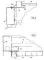
- la figure 1 est une vue éclatée et simplifiée, du principe de la structure du module selon l'invention,
- la figure 2 est une vue en coupe longitudinale de ce module,
- la figure 3 est une vue en coupe transversale de ce module,
- la figure 4 est une vue en coupe du module par un plan parallèle au plancher et plafond de ce dernier,
- la figure 5 est une vue agrandie du détail A de la figure 4,
- la figure 5A est une vue d'une variante de réalisation de ce détail A,
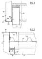
- la figure 6 est une vue agrandie du détail B de la figure 2,
- la figure 7 est une vue agrandie du détail C de la figure 2,
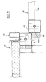
- la figure 8 est une vue agrandie du détail D de la figure 3,
- la figure 9 est une vue agrandie du détail E de la figure 3,
- la figure 10 illustre un module additionnel du module selon l'invention pour en augmenter la longueur,
- la figure 11 est une vue en coupe illustrant la coopération et le centrage de ce module additionnel avec celui de l'invention.
- FIG. 1 is an exploded and simplified view of the principle of the structure of the module according to the invention,
- FIG. 2 is a longitudinal sectional view of this module,
- FIG. 3 is a cross-sectional view of this module,
- FIG. 4 is a sectional view of the module by a plane parallel to the floor and ceiling of the latter,
- FIG. 5 is an enlarged view of detail A of FIG. 4,
- FIG. 5A is a view of an alternative embodiment of this detail A,
- FIG. 6 is an enlarged view of detail B of FIG. 2,
- FIG. 7 is an enlarged view of detail C of FIG. 2,
- FIG. 8 is an enlarged view of detail D of FIG. 3,
- FIG. 9 is an enlarged view of the detail E of FIG. 3,
- FIG. 10 illustrates an additional module of the module according to the invention for increasing its length,
- Figure 11 is a sectional view illustrating the cooperation and the centering of this additional module with that of the invention.
A la figure 1 on a représenté une structure de
plancher 1 formée par un cadre rectangulaire de tubes à
section rectangulaire comprenant deux longerons 2a et 2b
et deux traverses 3a et 3b. Aux angles de cette structure
rectangulaire, le plancher comporte des moignons en tubes
carrés 4 équipés d'une traverse 5 (voir figures 5, 5A et
11) qui servira à l'assemblage de la structure.In Figure 1 there is shown a floor structure 1 formed by a rectangular frame of rectangular section tubes comprising two
Quatre poteaux d'angles 6, tubulaires, identiques,
comportent à l'une de leurs extrémités un manchon
6a, dont les dimensions sont telles qu'il peut venir
s'encastrer à l'intérieur des moignons tubulaires de
plancher 4.Four
Un plafond 7 est formé de longerons 8a et 8b et
traverses 9a et 9b réalisés en tôle pliée et réunis entre
eux aux angles par des moignons 4' équipés de manchons
4'a semblables à ceux inférieurs des poteaux 6 destinés à
pénétrer dans ces poteaux.A
On notera enfin que la structure comporte pour le
plancher des solives 10 pour le soutien de matériaux de
parement, d'isolation ou d'étanchéité, tandis que le plafond
comporte des pannes 11 qui sont destinées à former
un appui pour une couverture faite en principe d'une tôle
nervurée ou ondulée à double pente dont les extrémités
les plus basses viennent se loger à l'intérieur des traverses
9a et 9b conformées en chêneaux de collecte des
eaux de pluie. Les figures suivantes illustreront plus en
détail les sections des différents éléments mis en oeuvre
dans cette structure.Finally, note that the structure comprises for the floor joists 10 for the support of facing materials, insulation or sealing, while the ceiling has
Le montage de la structure s'opère au moyen de
quatre tirants ou tiges filetées 13, chacun d'eux étant
logé dans chaque poteaux tubulaire 6 pour, à l'intérieur
des moignons 4 et 4', passer au travers de chacune des
traverses 5 que ce moignon comporte afin de recevoir de
part et d'autre de ces traverses des écrous de serrage et
d'assemblage du plancher et du plafond entretoisés par
les poteaux 6. On notera également que de manière connue,
les moignon 4 du plancher peuvent être prolongés par des
sortes de troncs de pyramides tubulaires qui permettent
l'empilement de deux modules par logement de ces troncs
de pyramides du module supérieur dans les moignons 4' de
la toiture du module inférieur.The assembly of the structure takes place by means of
four tie rods or threaded
Les figures 2 et 3 sont respectivement des coupes
longitudinale et transversale d'un module selon l'invention
sur lesquelles on retrouve les éléments déjà décrits
avec les mêmes références. On notera la présence du revêtement
de toiture 14 dont les nervures ou ondulations 14a
sont visibles à la figure 3, soutenues par la structure
de plafond 7. La structure de plancher 1 comporte un revêtement
de sol 15 sous lequel et au moyen des solives 19
on a logé du matériau d'isolation de manière traditionnelle.
A cet effet, les solives, longerons et traverses
possèdent des structures de tôle pliée en équerre telles
que celles référencées 16 aux figures, qui permettent le
maintien de ce matériau d'isolation se présentant sous
forme de panneaux.Figures 2 and 3 are respectively longitudinal and transverse sections of a module according to the invention on which we find the elements already described with the same references. Note the presence of the roofing felt 14, the ribs or
La figure 4 qui est une coupe dans un plan horizontal
du module selon l'invention, montre d'une part que
les poteaux 6 sont situés à l'extérieur des panneaux de
pignons 17 et que les parois de long pan 18 sont formées
de plusieurs panneaux juxtaposés 19 eux-mêmes à l'extérieur
des poteaux 6. Les figures suivantes illustreront à
plus grande échelle cette disposition.Figure 4 which is a section in a horizontal plane
of the module according to the invention, shows on the one hand that
the
La figure 5 qui est justement une vue à grande
échelle du détail A de la figure 4, comporte des éléments
déjà décrits avec les mêmes références. Ainsi, le poteau
tubulaire 6 est pourvu dans un angle d'une cornière ou
rail 20 de maintien du panneau ou de la paroi 17 de pignon
et ce, en retrait de la face 6c la plus extérieure
du poteau 6. Sur la face opposée 6d de ce poteau, c'est-à-dire
sa face la plus intérieure, on a adossé une goulotte
21 courant sur toute la hauteur du poteau et fixée
à ce dernier par tous moyens utiles par exemple des goujons
soudés 22 (figure 5A) et des écrous avec interposition
d'une couche isolante compacte 23. La face latérale
extérieure 6e du poteau 6 est équipée d'un profilé formé
par un profil métallique portant la référence 24 qui détermine
avec cette face 6e une feuillure 25 dans laquelle
un panneau tel que 19 de la paroi latérale de long pan 18
du module peut être glissé. Par ailleurs, ce profilé 24
définit un montant latéral de parement 26 qui affleure
avec la surface 6c de pignon du poteau 6 de manière à
augmenter sa largeur visible. Entre le montant 26 et la
feuillure 25, le profilé 24 définit un joint creux 27 qui
a une fonction esthétique et qui permet de loger de manière
quasiment invisible les vis 28 de sa fixation sur
toute la hauteur du poteau 6.Figure 5 which is precisely a large-scale view of detail A of Figure 4, comprises elements already described with the same references. Thus, the
A la figure 5A, on constate que la goulotte 21 de
la figure 5 qui est une goulotte simple pour le passage
d'une câblerie, avec par exemple un couvercle 21 amovible,
peut être remplacée par une structure profilée en
matière appropriée 29 délimitant une feuillure 30 de mise
en place non plus d'un panneau extérieur de long pan 19
mais d'une cloison de long pan 31 qui se trouve alors logée
totalement à l'intérieur du plan dans lequel se situent
les faces latérales extérieures 6e des poteaux de
long pan de sorte qu'ainsi on peut juxtaposer deux modules
l'un, pourvu de cette cloison 31 avec par exemple une
ouverture, une baie, une porte incorporée et l'autre, dépourvu
et de paroi extérieure 18 et du profilé 24 de manière
à pouvoir les juxtaposer exactement adjacents l'un
à l'autre. On voit que, au niveau du poteau, l'isolation
phonique et thermique est préservée même lors d'accolement
de deux modules puisque les couches 23 sont en continuité
l'une de l'autre.In FIG. 5A, it can be seen that the
La figure 6 est une vue de détail B de la figure
2 dans laquelle on retrouve une traverse de plancher 3b
équipée de ferrures 32, 32a formant une feuillure inférieure
pour recevoir le panneau de pignon 17, ces ferrures
32, 32a formant également un support d'extrémité 32b
pour le revêtement de sol 15 du plancher du module. On
aura noté en 4a la partie pyramidale déjà mentionnée du
moignon 4 servant à empiler deux modules.FIG 6 is a view of detail B of Figure 2 in which there are a
A la figure 7 on a représenté le détail C de la
figure 2, à savoir la traverse de toiture 9b conformée en
un chêneau 33 qui reçoit les écoulements de pluie ruisselants
sur la couverture 14. Cette traverse 9b comprend
également une ferrure en tôle pliée 34 qui forme une
feuillure 32 pour le panneau 17, à l'aplomb de la ferrure
inférieure représentée à la figure 6. Cette ferrure 34
constitue également le support latéral d'un faux plafond
35 qui peut contenir éventuellement un jeu de goulottes
36 pour la mise en place de gaines techniques circulant
parallèlement aux parois de pignon du module permettant
notamment l'intercommunication et l'interconnexion des
modules juxtaposés et/ou superposés.In Figure 7 there is shown detail C of Figure 2, namely the
La figure 8 est une vue agrandie du détail D de
la figure 3. On constate que le longeron de plancher 2a
est équipé de manière amovible d'un rail 37 qui sert au
soutien des panneaux 19 de la paroi 18 de long pan. Ce
rail est en forme de U ouvert vers le haut et le fond 37a
du U est en forme de V de sorte que le chant des panneaux
19 reposant sur ce fond 37a n'y repose que par ses bords
19a, 19b, ce qui limite le frottement entre le rail et le
panneau et donc facilite sa mise en place et son glissement
le long du long pan du module.Figure 8 is an enlarged detail D of Figure 3. It is noted that for the
Le détail E de la figure 3 est représenté de manière
agrandie à la figure 9. On y retrouve le longeron
de toiture 8a en forme de tôle pliée auquel un rail 38
est rapporté de manière amovible, ce rail faisant face au
rail inférieur 37 pour le maintien de la paroi de long
pan 18 formé de panneaux 19. On notera également que le
longeron 8a possède en partie inférieure des ferrures 39
et 39' également en profils métalliques qui permettent
d'une part de soutenir le bord latéral du faux plafond 35
et, d'autre part, de constituer un support pour une goulotte
technique 40 qui, ainsi, court le long de chaque
côté du volume intérieur du module. Cette goulotte 40 est
du même style que la goulotte 21 de la figure 5 et communique
avec elle.The detail E of Figure 3 is shown in an enlarged manner in Figure 9. It includes the roof rail 8 is in folded form sheet metal to which a
On a représenté schématiquement à la figure 10,
un module 41 conforme à l'invention auquel on peut adjoindre
en extrémité, c'est-à-dire en pignon un module
auxiliaire ou additionnel 42 dont la structure est sensiblement
identique à celle du module 41. Le module 42 est
beaucoup moins long que le module 41 ; il est destiné à
constituer une prolongation de ce module 41, en pignon,
pour former par exemple un espace de circulation desservant
des modules 41 juxtaposés ou des espaces dédiés à de
multiples usages, dont simplement l'extension de bureaux
et salles diverses, ou encore la création d'espaces ouverts,
de terrasses, balcons, coursives, une sorte de
bow-window permettant d'aménager un espace d'agrément,
par exemple une serre... Diagrammatically shown in FIG.
a
On a représenté en figure 11 une coupe illustrant
la position relative de ces modules 41 et 42 au niveau
des poteaux de pignon 6 pour le module 41 et 43 pour le
module 42. On a illustré un panneau latéral 44 du module
42 formé par exemple d'une baie vitrée ou tout autre remplissage,
comme un garde-corps. Chaque poteau 43 de ce
module 42 porte sur sa face extrême 43a une console 45
qui fait saillie vers l'extérieur du pignon et qui constitue
un moyen de guidage, de centrage et d'appui pour
charges verticales du module 42 dans le pignon du module
41 en venant se glisser à l'intérieur des poteaux 6 de ce
module 41. L'assemblage de ces deux modules est réalisé
par exemple par boulonnage au niveau des traverses de pignons
telles que celles 3b et 9b représentées respectivement
aux figures 6 et 7. On aura noté le léger retrait
latéral des poteaux 43 par rapport aux poteaux 6 du module
principal 41. Le plan de façade latérale du module
auxiliaire est en retrait par rapport au plan de la façade
latérale du module principal qui donne à ce module
additionnel un aspect de "tiroir" extrait du module principal.FIG. 11 shows a section illustrating the relative position of these
Les panneaux de long pan comme d'ailleurs les
panneaux de pignon peuvent être pourvus d'ouvertures telles
que des portes ou des fenêtres à baies fixes ou ouvrantes
totalement incorporées dans ces panneaux. Le montage
sur la structure du module consiste essentiellement
à glisser la partie supérieure de chaque panneau dans les
rails ou ferrures 38 et 34 de long pan et de pignon de
manière à pouvoir passer les rebords extérieurs des rails
et ferrures 32 et 37 pour que le chant inférieur des panneaux
17, 18, 19 puisse retomber dans les rails ou
feuillures 37, 32.The Pan Long Panels as well as the
pinion panels can be provided with openings such
doors or windows with fixed or opening windows
totally incorporated in these panels. Mounting
on the structure of the module basically consists
to slide the top of each panel into the
rails or
Claims (7)
Applications Claiming Priority (2)
| Application Number | Priority Date | Filing Date | Title |
|---|---|---|---|
| FR0401387A FR2866365B1 (en) | 2004-02-12 | 2004-02-12 | MODULE FOR MODULAR CONSTRUCTION SYSTEM |
| FR0401387 | 2004-02-12 |
Publications (2)
| Publication Number | Publication Date |
|---|---|
| EP1564337A1 true EP1564337A1 (en) | 2005-08-17 |
| EP1564337B1 EP1564337B1 (en) | 2012-06-13 |
Family
ID=34685009
Family Applications (1)
| Application Number | Title | Priority Date | Filing Date |
|---|---|---|---|
| EP20050290238 Active EP1564337B1 (en) | 2004-02-12 | 2005-02-03 | Module for modular construction system |
Country Status (3)
| Country | Link |
|---|---|
| EP (1) | EP1564337B1 (en) |
| ES (1) | ES2388820T3 (en) |
| FR (1) | FR2866365B1 (en) |
Cited By (7)
| Publication number | Priority date | Publication date | Assignee | Title |
|---|---|---|---|---|
| FR2919636A1 (en) * | 2007-08-03 | 2009-02-06 | Modulaire Innovation Sarl | House e.g. outdoor accommodation, has right and left side modules connected by center module, where connection between modules are formed by removable attachment structure to add or remove center module between side modules |
| EP2110485A1 (en) | 2008-04-18 | 2009-10-21 | Algeco | Construction module with improved fire resistance |
| DE202009002015U1 (en) * | 2009-03-31 | 2010-08-19 | Az1 Containerhandelsgesellschaft Mbh | office Trailers |
| AU2010202450A1 (en) * | 2009-06-12 | 2011-01-06 | Alexander Patrick Scales | Modular building structures |
| FR2991696A1 (en) * | 2012-06-11 | 2013-12-13 | Yves Cougnaud | Floor framework for modular construction of office building, has release part located on side of support part away from center, and discharge openings discharging water collected in space between support part and wall panel lower part |
| FR2991695A1 (en) * | 2012-06-11 | 2013-12-13 | Yves Cougnaud | MODULAR CONSTRUCTION AND CORRESPONDING ASSEMBLY METHOD |
| BE1025256B1 (en) * | 2017-10-23 | 2018-12-19 | Constructie Bedrijf Zutendaal N.V. | Modular building unit |
Citations (4)
| Publication number | Priority date | Publication date | Assignee | Title |
|---|---|---|---|---|
| US3971172A (en) * | 1974-05-08 | 1976-07-27 | Industrielle De Constructions Mobiles | Prefabricated construction |
| GB2282395A (en) * | 1993-08-12 | 1995-04-05 | Optima Building Systems Intern | Building system |
| WO1996011307A1 (en) * | 1994-10-11 | 1996-04-18 | F.A.E. Industria Alloggi Prefabbricati S.P.A | Prefabricated residence block |
| FR2832744A1 (en) * | 2001-11-23 | 2003-05-30 | Loxam Module | Modular and movable construction unit has transverse tubular beams in base frame for handling and for supporting outer adjoining structures |
-
2004
- 2004-02-12 FR FR0401387A patent/FR2866365B1/en not_active Expired - Lifetime
-
2005
- 2005-02-03 ES ES05290238T patent/ES2388820T3/en active Active
- 2005-02-03 EP EP20050290238 patent/EP1564337B1/en active Active
Patent Citations (4)
| Publication number | Priority date | Publication date | Assignee | Title |
|---|---|---|---|---|
| US3971172A (en) * | 1974-05-08 | 1976-07-27 | Industrielle De Constructions Mobiles | Prefabricated construction |
| GB2282395A (en) * | 1993-08-12 | 1995-04-05 | Optima Building Systems Intern | Building system |
| WO1996011307A1 (en) * | 1994-10-11 | 1996-04-18 | F.A.E. Industria Alloggi Prefabbricati S.P.A | Prefabricated residence block |
| FR2832744A1 (en) * | 2001-11-23 | 2003-05-30 | Loxam Module | Modular and movable construction unit has transverse tubular beams in base frame for handling and for supporting outer adjoining structures |
Cited By (9)
| Publication number | Priority date | Publication date | Assignee | Title |
|---|---|---|---|---|
| FR2919636A1 (en) * | 2007-08-03 | 2009-02-06 | Modulaire Innovation Sarl | House e.g. outdoor accommodation, has right and left side modules connected by center module, where connection between modules are formed by removable attachment structure to add or remove center module between side modules |
| EP2110485A1 (en) | 2008-04-18 | 2009-10-21 | Algeco | Construction module with improved fire resistance |
| FR2930268A1 (en) * | 2008-04-18 | 2009-10-23 | Algeco Sa | BUILDING MODULE HAVING IMPROVED FIRE. |
| DE202009002015U1 (en) * | 2009-03-31 | 2010-08-19 | Az1 Containerhandelsgesellschaft Mbh | office Trailers |
| AU2010202450A1 (en) * | 2009-06-12 | 2011-01-06 | Alexander Patrick Scales | Modular building structures |
| FR2991696A1 (en) * | 2012-06-11 | 2013-12-13 | Yves Cougnaud | Floor framework for modular construction of office building, has release part located on side of support part away from center, and discharge openings discharging water collected in space between support part and wall panel lower part |
| FR2991695A1 (en) * | 2012-06-11 | 2013-12-13 | Yves Cougnaud | MODULAR CONSTRUCTION AND CORRESPONDING ASSEMBLY METHOD |
| EP2674538A1 (en) * | 2012-06-11 | 2013-12-18 | Cougnaud, Yves | Modular construction and corresponding assembly method |
| BE1025256B1 (en) * | 2017-10-23 | 2018-12-19 | Constructie Bedrijf Zutendaal N.V. | Modular building unit |
Also Published As
| Publication number | Publication date |
|---|---|
| FR2866365A1 (en) | 2005-08-19 |
| ES2388820T3 (en) | 2012-10-18 |
| EP1564337B1 (en) | 2012-06-13 |
| FR2866365B1 (en) | 2006-04-07 |
Similar Documents
| Publication | Publication Date | Title |
|---|---|---|
| EP1564337B1 (en) | Module for modular construction system | |
| CA2398882A1 (en) | Structural profiled section in particular for partition | |
| FR2568288A1 (en) | Swimming pool shelter consisting of telescopic elements which may or may not be installed on rails | |
| WO2010086533A1 (en) | Module for a modular construction system, and modular construction consisting of said modules | |
| EP1130193A1 (en) | Fast build construction | |
| FR2963801A1 (en) | MODULAR DEVICE FOR ENSURING THE COVERAGE OF A SURFACE SUCH AS THE ROOF OF A BUILDING AND THE PRODUCTION OF ELECTRICITY | |
| WO2001088293A1 (en) | Building framework | |
| FR2894265A1 (en) | Modular construction system for forming e.g. workshop, has main module assembly including construction components disposed parallelly at regular intervals, and floor joists placed between lateral elements of levels connecting components | |
| EP2103756A2 (en) | Solar protection structure | |
| FR2960578A1 (en) | Modular construction element for constructing portable temporary buildings i.e. shelters, has sealing joint extending between perpendicular surface and beveled junction surface, and framework comprising horizontal crosspieces | |
| EP0081496B1 (en) | Industrialized metallic multi-storey building system with elements finished at the work-shop | |
| FR2576341A1 (en) | Building structure having modular panels | |
| EP0320359B1 (en) | Appliance for a light building-façade | |
| FR2527671A1 (en) | Self supporting undulating roofing modules - incorporating composite panels with cellular cores, pref. of phenolic or polyurethane foam between metal covers | |
| EP2206844A1 (en) | Multi purpose structure | |
| EP1790793A1 (en) | Assembly for collecting and conveying rain water and for the connection of facade panels for a lightweight prefabricated building | |
| BE889198A (en) | INDUSTRIALIZED METAL STORED BUILDING SYSTEM WITH WORKSHOP COMPLETE ELEMENTS | |
| FR2563858A1 (en) | Rapidly-installed habitable module for hot countries | |
| FR2762631A1 (en) | Closure for roof opening | |
| FR2733263A1 (en) | COMPOSITE PANEL, PANEL ASSEMBLY AND PREFABRICATED TYPE BUILDING CONSTRUCTED USING SUCH PANELS | |
| FR2824853A1 (en) | Structure for transportable house comprises two modules each composed of floor, roof and walls comprising side by side rigid insulating panels | |
| EP0365512A1 (en) | Prefabricated construction units for building constructions, and construction process of buildings using these building units | |
| FR3133869A1 (en) | Canopy-type installation for an exterior building door | |
| EP3418463A1 (en) | Connection device between the vertical walls and the roof of a veranda-type lightweight construction | |
| FR2669357A1 (en) | Construction of walls, in particular walls or building coverings made of glass |
Legal Events
| Date | Code | Title | Description |
|---|---|---|---|
| PUAI | Public reference made under article 153(3) epc to a published international application that has entered the european phase |
Free format text: ORIGINAL CODE: 0009012 |
|
| AK | Designated contracting states |
Kind code of ref document: A1 Designated state(s): AT BE BG CH CY CZ DE DK EE ES FI FR GB GR HU IE IS IT LI LT LU MC NL PL PT RO SE SI SK TR |
|
| AX | Request for extension of the european patent |
Extension state: AL BA HR LV MK YU |
|
| 17P | Request for examination filed |
Effective date: 20060125 |
|
| AKX | Designation fees paid |
Designated state(s): BE DE ES FR NL |
|
| 17Q | First examination report despatched |
Effective date: 20061206 |
|
| GRAP | Despatch of communication of intention to grant a patent |
Free format text: ORIGINAL CODE: EPIDOSNIGR1 |
|
| GRAS | Grant fee paid |
Free format text: ORIGINAL CODE: EPIDOSNIGR3 |
|
| GRAA | (expected) grant |
Free format text: ORIGINAL CODE: 0009210 |
|
| AK | Designated contracting states |
Kind code of ref document: B1 Designated state(s): BE DE ES FR NL |
|
| REG | Reference to a national code |
Ref country code: DE Ref legal event code: R096 Ref document number: 602005034645 Country of ref document: DE Effective date: 20120809 |
|
| REG | Reference to a national code |
Ref country code: NL Ref legal event code: T3 |
|
| REG | Reference to a national code |
Ref country code: ES Ref legal event code: FG2A Ref document number: 2388820 Country of ref document: ES Kind code of ref document: T3 Effective date: 20121018 |
|
| PLBE | No opposition filed within time limit |
Free format text: ORIGINAL CODE: 0009261 |
|
| STAA | Information on the status of an ep patent application or granted ep patent |
Free format text: STATUS: NO OPPOSITION FILED WITHIN TIME LIMIT |
|
| 26N | No opposition filed |
Effective date: 20130314 |
|
| REG | Reference to a national code |
Ref country code: DE Ref legal event code: R097 Ref document number: 602005034645 Country of ref document: DE Effective date: 20130314 |
|
| BERE | Be: lapsed |
Owner name: ALGECO Effective date: 20130228 |
|
| REG | Reference to a national code |
Ref country code: NL Ref legal event code: V1 Effective date: 20130901 |
|
| PG25 | Lapsed in a contracting state [announced via postgrant information from national office to epo] |
Ref country code: NL Free format text: LAPSE BECAUSE OF NON-PAYMENT OF DUE FEES Effective date: 20130901 |
|
| REG | Reference to a national code |
Ref country code: DE Ref legal event code: R119 Ref document number: 602005034645 Country of ref document: DE Effective date: 20130903 |
|
| PG25 | Lapsed in a contracting state [announced via postgrant information from national office to epo] |
Ref country code: BE Free format text: LAPSE BECAUSE OF NON-PAYMENT OF DUE FEES Effective date: 20130228 Ref country code: DE Free format text: LAPSE BECAUSE OF NON-PAYMENT OF DUE FEES Effective date: 20130903 |
|
| REG | Reference to a national code |
Ref country code: ES Ref legal event code: FD2A Effective date: 20140409 |
|
| REG | Reference to a national code |
Ref country code: FR Ref legal event code: GC Effective date: 20140324 |
|
| PG25 | Lapsed in a contracting state [announced via postgrant information from national office to epo] |
Ref country code: ES Free format text: LAPSE BECAUSE OF NON-PAYMENT OF DUE FEES Effective date: 20130204 |
|
| REG | Reference to a national code |
Ref country code: FR Ref legal event code: PLFP Year of fee payment: 12 |
|
| REG | Reference to a national code |
Ref country code: FR Ref legal event code: GC Effective date: 20161216 |
|
| REG | Reference to a national code |
Ref country code: FR Ref legal event code: PLFP Year of fee payment: 13 |
|
| REG | Reference to a national code |
Ref country code: FR Ref legal event code: GC Effective date: 20170616 |
|
| REG | Reference to a national code |
Ref country code: FR Ref legal event code: PLFP Year of fee payment: 14 |
|
| PGFP | Annual fee paid to national office [announced via postgrant information from national office to epo] |
Ref country code: FR Payment date: 20230220 Year of fee payment: 19 |