EP1562723B1 - Dispositif et procede d'usinage de pieces - Google Patents
Dispositif et procede d'usinage de pieces Download PDFInfo
- Publication number
- EP1562723B1 EP1562723B1 EP03769406.4A EP03769406A EP1562723B1 EP 1562723 B1 EP1562723 B1 EP 1562723B1 EP 03769406 A EP03769406 A EP 03769406A EP 1562723 B1 EP1562723 B1 EP 1562723B1
- Authority
- EP
- European Patent Office
- Prior art keywords
- bristles
- workpiece
- brush
- belt
- conveyor
- Prior art date
- Legal status (The legal status is an assumption and is not a legal conclusion. Google has not performed a legal analysis and makes no representation as to the accuracy of the status listed.)
- Expired - Lifetime
Links
- 238000000034 method Methods 0.000 title claims description 10
- 238000003754 machining Methods 0.000 title description 8
- 239000002184 metal Substances 0.000 claims description 21
- 229910052751 metal Inorganic materials 0.000 claims description 21
- 239000004033 plastic Substances 0.000 claims description 10
- 229920003023 plastic Polymers 0.000 claims description 10
- 229910000831 Steel Inorganic materials 0.000 claims description 8
- 229920001971 elastomer Polymers 0.000 claims description 8
- 239000005060 rubber Substances 0.000 claims description 8
- 239000010959 steel Substances 0.000 claims description 8
- 239000000463 material Substances 0.000 claims description 4
- 229920001084 poly(chloroprene) Polymers 0.000 claims description 3
- 239000000969 carrier Substances 0.000 claims description 2
- 229920003051 synthetic elastomer Polymers 0.000 claims description 2
- 239000005061 synthetic rubber Substances 0.000 claims description 2
- 230000003019 stabilising effect Effects 0.000 claims 2
- 238000000465 moulding Methods 0.000 claims 1
- 238000004080 punching Methods 0.000 claims 1
- 230000003319 supportive effect Effects 0.000 claims 1
- 238000003466 welding Methods 0.000 claims 1
- 238000012545 processing Methods 0.000 description 13
- 238000002474 experimental method Methods 0.000 description 11
- 238000000227 grinding Methods 0.000 description 8
- 238000004140 cleaning Methods 0.000 description 5
- 238000013461 design Methods 0.000 description 5
- 239000004814 polyurethane Substances 0.000 description 4
- 230000000087 stabilizing effect Effects 0.000 description 4
- 230000006378 damage Effects 0.000 description 3
- 238000005246 galvanizing Methods 0.000 description 3
- 238000003780 insertion Methods 0.000 description 3
- 230000035515 penetration Effects 0.000 description 3
- 238000005452 bending Methods 0.000 description 2
- 238000010073 coating (rubber) Methods 0.000 description 2
- 239000011248 coating agent Substances 0.000 description 2
- 238000000576 coating method Methods 0.000 description 2
- 238000005520 cutting process Methods 0.000 description 2
- 230000000694 effects Effects 0.000 description 2
- 230000037431 insertion Effects 0.000 description 2
- 238000012986 modification Methods 0.000 description 2
- 230000004048 modification Effects 0.000 description 2
- 238000010422 painting Methods 0.000 description 2
- 238000003860 storage Methods 0.000 description 2
- 235000013358 Solanum torvum Nutrition 0.000 description 1
- 240000002072 Solanum torvum Species 0.000 description 1
- 208000027418 Wounds and injury Diseases 0.000 description 1
- HCHKCACWOHOZIP-UHFFFAOYSA-N Zinc Chemical compound [Zn] HCHKCACWOHOZIP-UHFFFAOYSA-N 0.000 description 1
- 238000005299 abrasion Methods 0.000 description 1
- 230000001680 brushing effect Effects 0.000 description 1
- 150000001875 compounds Chemical class 0.000 description 1
- 230000001419 dependent effect Effects 0.000 description 1
- 239000000428 dust Substances 0.000 description 1
- 230000008676 import Effects 0.000 description 1
- 239000012535 impurity Substances 0.000 description 1
- 208000014674 injury Diseases 0.000 description 1
- 230000001788 irregular Effects 0.000 description 1
- 238000003698 laser cutting Methods 0.000 description 1
- 238000012423 maintenance Methods 0.000 description 1
- 239000003973 paint Substances 0.000 description 1
- 230000002093 peripheral effect Effects 0.000 description 1
- 229920002635 polyurethane Polymers 0.000 description 1
- 238000003825 pressing Methods 0.000 description 1
- 239000004576 sand Substances 0.000 description 1
- 238000004901 spalling Methods 0.000 description 1
- 230000006641 stabilisation Effects 0.000 description 1
- 238000011105 stabilization Methods 0.000 description 1
- 238000001238 wet grinding Methods 0.000 description 1
- 239000011701 zinc Substances 0.000 description 1
- 229910052725 zinc Inorganic materials 0.000 description 1
Images


Classifications
-
- B—PERFORMING OPERATIONS; TRANSPORTING
- B24—GRINDING; POLISHING
- B24B—MACHINES, DEVICES, OR PROCESSES FOR GRINDING OR POLISHING; DRESSING OR CONDITIONING OF ABRADING SURFACES; FEEDING OF GRINDING, POLISHING, OR LAPPING AGENTS
- B24B29/00—Machines or devices for polishing surfaces on work by means of tools made of soft or flexible material with or without the application of solid or liquid polishing agents
- B24B29/005—Machines or devices for polishing surfaces on work by means of tools made of soft or flexible material with or without the application of solid or liquid polishing agents using brushes
-
- B08B1/20—
-
- B08B1/32—
-
- B—PERFORMING OPERATIONS; TRANSPORTING
- B24—GRINDING; POLISHING
- B24B—MACHINES, DEVICES, OR PROCESSES FOR GRINDING OR POLISHING; DRESSING OR CONDITIONING OF ABRADING SURFACES; FEEDING OF GRINDING, POLISHING, OR LAPPING AGENTS
- B24B21/00—Machines or devices using grinding or polishing belts; Accessories therefor
- B24B21/04—Machines or devices using grinding or polishing belts; Accessories therefor for grinding plane surfaces
-
- B—PERFORMING OPERATIONS; TRANSPORTING
- B24—GRINDING; POLISHING
- B24B—MACHINES, DEVICES, OR PROCESSES FOR GRINDING OR POLISHING; DRESSING OR CONDITIONING OF ABRADING SURFACES; FEEDING OF GRINDING, POLISHING, OR LAPPING AGENTS
- B24B27/00—Other grinding machines or devices
- B24B27/033—Other grinding machines or devices for grinding a surface for cleaning purposes, e.g. for descaling or for grinding off flaws in the surface
Definitions
- the invention relates to a device and a method for processing a band-shaped or plate-shaped metallic workpiece, in particular for removing the oxide layer of cut surfaces and / or cut edges of the workpiece.
- an oxide layer or an oxide skin is formed at the cut edges and at the cut surfaces.
- a disadvantage of the oxide layer is that a paint or zinc coating applied to it bounces off relatively quickly. For this reason, the metallic workpieces are ground off before painting and galvanizing.
- the generic document shows a method and apparatus for removing the oxide skin on metal blanks.
- the metal blank is used to remove the oxide layer passed from the cut surfaces between paired, rotating, machining tools.
- the outer cut surfaces of the oxide layer can be cleaned by this method, it is not possible to remove the oxide layer from inner cut surfaces, for example from recesses or similar openings in the workpiece.
- the metal blank must be fed to a further processing device, if the surface or the main surface of the workpiece to be cleaned or cleaned.
- a disadvantage of the device of the generic document is also the handling, and the cost-intensive design and high space requirements.
- the processing tools use uneven, since it is generally assumed that the metal blanks to be descaled always in the same area, i. in the same place, so that one part of the machining tool never comes into contact with the metal blank, while another part of the machining tool is subject to permanent wear.
- Devices for deburring and fine grinding are also known from the general state of the art.
- both rollers and plate-shaped, rotating brush tools are used.
- the workpiece to be machined is placed on a horizontal working plane or a conveyor belt and performed under the roller or the rotary brush tool by hand or automatically.
- Such machines can for example have a working width of 1 to 2 m, but in practice usually equipped with smaller metal blanks. This has the consequence that a roll with for example 2 m in length is only claimed on the first 50 cm of its length of metal blanks and thus wears only in this area.
- the roller must be replaced as soon as this area is worn out too much, although three quarters of the roller surface is still well preserved and usable. An exchange is therefore unavoidable, since when introducing a large workpiece now no longer grind the first 50 cm of the roller. The uneven wear of the roller and the resulting different pressure on the workpiece result in inferior grinding results. On the quality of deburring or grinding also has a negative effect that the brush or the roller is not infinitely adjustable in their penetration depth. An inherently meaningful, deep penetration of the bristles is prevented by the conveyor belt on which the workpiece lies, as this should not be damaged.
- a disadvantage of the known deburring and grinding machines is also that the workpiece must be inserted twice so that both main surfaces of the workpiece can be edited.
- Another disadvantage of the known machines is the high drive power, the high space requirement and the high acquisition and maintenance costs.
- the basic surfaces of the machines are dimensioned so that even the largest workpieces can be inserted and processed flat.
- the base requires at least such a space requirement. Added to this is the space required for placing and aligning the piece of metal prior to insertion into the machine and for removal.
- each wiping element wipes one side of a plate-shaped workpiece.
- the wiping elements work transversely to the feed direction of the workpiece.
- a device for cleaning surfaces with endless circulating cleaning tapes is known, which is transverse to the passage direction of the cleaned Circulating workpiece. It can be provided that a device acts from above and a device from below on the workpiece.
- the present invention has for its object to solve the above-mentioned disadvantages of the prior art, in particular a fast, simple and inexpensive device and a method for processing strip or plate-shaped metallic workpieces, in particular for removing the oxide layer of cut surfaces and / or cut edges to create the same.
- a method for processing a metallic workpiece results from claim 35.
- the brush does not remain rigidly in one position due to the arrangement on a circulating conveyor, but is guided along the entire length which is present for the passage of the workpiece, a uniform wear of the at least one brush is ensured.
- the workpiece can be carried out in a simple manner obliquely, preferably transversely to the direction of rotation of the brush or pulled through, so that the workpiece is processed uniformly by the brush.
- the brush thus moves obliquely or transversely to the feed direction of the workpiece along the workpiece and, similar to a brush, which is pulled along on a metal piece, penetrates into each recess.
- both the surfaces i. the main surfaces of the band- or plate-shaped metal workpieces machined, as well as the cut surfaces and cut edges descaled. Simultaneous descaling of the cut surfaces and cut edges and cleaning of the surfaces was not possible with the previously known devices.
- both main surfaces of the workpiece are thereby processed with one operation.
- the cut edges and the cut surfaces are processed from both sides, so that a very thorough descaling takes place.
- the use of two conveyors allows a fast and rational machining of the workpiece.
- the conveying devices have a plurality of brushes arranged at a distance from one another.
- the distance between the brushes ensures that the brushes each hit unbelted on the workpiece or advantageously penetrate into recesses or holes.
- the bristles are corrugated and / or formed rotated.
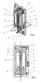
- Fig. 1 shows an apparatus for processing a band- or plate-shaped metal workpiece 1 (in Fig. 3 and Fig. 6 exemplified).
- the device according to the invention is particularly suitable for removing the oxide layer from cut surfaces 1b and / or cut edges 1a of the workpieces 1.
- Both circumferential cut surfaces 1b and cut edges 1a of the workpiece 1 and cut surfaces 1b and cut edges 1a of recesses, holes or the like can be used the workpiece 1 are descaled. In experiments, it has been found that small holes generally do not have to be descaled, since they usually serve as screw holes and therefore painting or galvanizing is not absolutely necessary.
- workpieces 1 can be cleaned so advantageously of oxide layers or of impurities on the two main surfaces 1c or the surface of the workpiece 1 that a reliable and permanent coating or galvanizing is possible without a later spalling of the applied layer must be feared.
- the device according to the invention has two conveyor devices 2, which are each provided with brushes 3.
- the conveyors 2 guide the brushes 3 at least approximately linearly in the area of the workpiece 1 to be machined.
- the workpiece 1 to be machined is carried out or pulled through transversely to the direction of rotation of the conveyors 2 between the two conveyors 2.
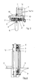
- the inventive Device a guide channel 4, which also off Fig. 3 it is apparent.
- the guide channel 4 can be adjusted by means of an adjusting device 5.
- the device according to the invention has a sheet metal insert 6, through which the workpiece 1 can be introduced into the guide channel 4. After passing through the guide channel 4 or after passing through the two conveyors 2, the workpiece 1 is discharged onto a storage table 7. To push through the workpiece 1, a push plate or the next subsequent workpiece 1 may be provided.
- the delivery table 7 can have a vertical stop, which ensures that the workpiece 1 after delivery from the guide channel 4 in a defined direction can fall or be folded over (see Fig. 4 ).
- the guide channel 4 is also designed to guide the brushes 3 so that they are moved along the workpiece 1 in a defined manner and can not escape.
- the device according to the invention has an independent feed 8, by means of which the depth of engagement of the brushes 3 can be varied. This is particularly advantageous for correcting the wear of the brushes 3 or for increasing the pressure.
- these are moved to adjust the wear of the brush 3 to each other or adjusted.
- this is moved to a fixed wall of the guide channel 4, which serves as a counter-holder or as a replacement for the second conveyor 2 in this case, or adjusted.
- an adjustment of the guide channel 4 may be provided in the direction of the conveyor 2.
- the adjusting device 5 and the delivery 8 are formed with spindles.
- the spindles of the adjusting device 5 and the delivery 8 can be connected via a respective chain and provided with a worm gear.
- the conveyors 2 are arranged slightly offset from one another in the direction of passage of the workpiece 1.
- the offset in the direction of passage may be, for example, 10 to 100 mm, preferably 30 mm.
- the solution according to the invention in a manner not shown, be provided with horizontally arranged conveyors 2, so that the brushes 3 are arranged in the region of the workpiece 1 extending substantially horizontally.
- the direction of rotation of the conveyors 2 is selected such that the brushes 3 of both conveyors 2 in the same direction on the two main surfaces 1c of the workpiece are fed past.
- the direction of rotation of the conveyors 2 is, as out Fig. 2 can be seen, selected such that the brushes 3 from top to bottom or toward a in Fig. 4 shown bottom plate 9 are guided past the workpiece 1.
- This running direction results in a particularly advantageous removal of dirt and high stability Device according to the invention and the workpiece to be machined 1, as this is not uncontrolled moved by the brushes 3, but is pressed firmly and stably on the bottom plate 9.
- the direction of rotation of the conveyors 2 is selected such that the brushes 3 along the workpiece 1 in the direction of a boundary plate, which the workpiece 1 at a Front side leads, are passable. Analogous to the contact pressure of the workpiece 1 on the bottom plate 9 in the stationary embodiment of the conveyors 2, the workpiece 1 is thus pressed stably on the boundary plate.
- the second and third conveying means 2 in the direction of passage of the workpiece 1 consequently run in such a way that they are in contact therewith arranged brush 3 in the region of the workpiece 1 to move in opposite directions to the first and the fourth conveyor.
- This arrangement ensures that the workpiece 1 is pressed by the first conveyor 2 down in the direction of the bottom plate 9, the two next conveyors 2 press the workpiece 1 while upwards, this immediately by the subsequent fourth conveyor 2, which presses the workpiece 1 down again, is corrected.
- the first and the third conveyor as well as the second and the fourth conveyor are arranged on one side of the workpiece 1 or on a main surface 1c.
- Fig. 1 to Fig. 5 illustrated embodiment of the device according to the invention with two conveyors 2, it may be necessary that the workpiece 1 is reversed and pushed through again. This is when looking at the Fig. 6 simply conceivable, since the brush 3 of course facing the direction of rotation Sand side surfaces 1b and side edges 1a better than the side surfaces 1b and side edges 1a, which are oppositely oriented (so to speak, in the "slipstream" lie).
- Fig. 18 illustrated variant of the solution according to the invention with four conveyors 2, in which each two conveyors 2 brush to the right and two to the left, turning over and re-pushing the workpiece 1 is not necessary.
- the workpiece is finished with a single push through.
- an automatic feed for carrying out the workpieces 1 can be provided.
- Fig. 5 shows the device according to the invention with a housing 11.
- Both the sheet metal insert 6 and the storage table 7 can be designed to be height adjustable. It can also be provided that the width of the sheet metal insert 6 and / or the tray table 7 is adjustable.
- the bristles 12 are in a simplified Presentation straight running. In an advantageous embodiment, however, it can be provided that the bristles 12 are corrugated or rotated, so that the bundles 120 formed by the bristles 12 resemble a scrubby brush or a tuft.
- the conveyor 2 is provided with a V-belt 13.
- V-belt 13 may also be a toothed belt, a flat belt with knobs, a chain, a belt or the like may be provided.
- the V-belt 13 is formed in the illustrated embodiment as a "triple" V-belt 13 with two outer V-belts 13b, 13c and a central V-belt 13a.
- the middle V-belt 13 a is provided for receiving the brushes 3.
- the V-belt 13 may be formed of rubber, plastic, synthetic rubber or preferably neoprene. It can generally be provided that the brushes 3 or the bristles 12 are glued, cast, bolted, punched or welded to the V-belt 13. In the exemplary embodiment, it is provided that a PU cover layer (polyurethane) 14 is applied to the V-belt 13.
- a support 15 preferably formed of rubber or plastic (e.g., neoprene) for the brush 3 and the bristles 12, respectively, can be easily welded. The result is an advantageous and reliable connection.
- the PU layer 14 may have a thickness of 1 to 5 mm, preferably 2 mm.
- the V-belt 13 can with several individual brushes 3 ( Fig. 6 ) or with a single V-belt 13 completely covering brush 3 ( Fig. 17 ) be provided.
- the bristles 12 can be shot in bundles 120 in the carrier 15.
- a secure and reliable connection of both the carrier 15 with the V-belt 13 and between the carrier 15 and the shot bundles 120 is ensured.
- a reliable connection is essential due to the high number of revolutions and the forces involved. As a result, high brushing speeds can be used.
- the design of the conveyor 2 as a belt drive with a V-belt 13 is smooth and reliable.
- the bristles 12 may be provided with not shown barbs.
- the V-belt 13 is formed in the embodiment as a so-called power band. It has been found in experiments that the outer two V-belts 13b, 13c sufficient to drive, so that the central V-belt 13a can be easily used to accommodate the bristles 12.
- the carrier 15 is provided transversely to the direction of rotation of the conveyor 2 and the V-belt 13 with slots 16.
- the carrier 15 in a manner not shown, also be formed of individual segments in similar dimensions. It can be provided that 16 portions 15a of the carrier 15 are formed by the slots, which have a length of 10 to 40 mm. In the exemplary embodiment, it is provided that both the length and the width of the sections 15a is 18 mm.
- Each section 15 a takes on a bundle 120 of the Bosten 12. Each form three sections 15a together, a brush 3. Of course, here are other combinations conceivable, for example, two or four sections 15a taken together can form a complete brush 3.
- the number of bristles 12 per bundle 120 is not limited to the illustrated number, but it is intended to combine a plurality of bristles into a bundle 120.
- the carrier 15 is divided by the slots 16 into sections 15a, results in a particularly small bending radius, so that the entire device can be made to save space and cost.
- the length of the bristles 12 is 30 to 90 mm, preferably 60 mm.
- the carrier 15 may be formed of the same material as the V-belt 13. In this case, various embodiments are conceivable which are suitable for shooting in the bristles 12 are and can be reliably welded to the PU cover layer 14.
- FIGS. 10a to 10d Various advantageous embodiments of the V-belt 13 can be seen.
- the V-belts 13 according to Fig. 10a to Fig. 10d in this case have elevations or projections 17 on their upper side to be provided with the carrier 15, which are intended to guide or support the carrier 15.
- Fig. 10a in this case shows a triangular-shaped projection 17 in cross-section, which runs parallel to the central V-belt 13a.
- carrier 15 in this case preferably has a projection 17 corresponding recess, whereby a particularly reliable connection between the carrier 15 and the belt 13 is formed.
- Fig. 10b shows a particularly preferred embodiment of the V-belt 13, which also in Fig. 11 is shown.
- the V-belt 13 according to Fig. 10b in this case has two projections 17, which laterally guide or support the carrier 15.
- the width of the carrier 15 and the distances between the projections 17 are preferably matched to one another.
- Fig. 10c shows one too Fig. 10a alternative embodiment of the projection 17, which also extends parallel to the central V-belt 13a.
- a groove / spring connection between the carrier 15 and the V-belt 13 is provided.
- Fig. 10d shows one too Fig. 10b simplified design of the V-belt 13, in which the carrier 15 only at one Side is guided or stabilized by a projection 17. As has been found in experiments, already sufficient lateral projection to achieve an improvement in the connection between the carrier 15 and the belt 13.
- the projections 17 according to the FIGS. 10a to 10d advantageously prevent rotation or rotational movement of the carrier 15.
- FIGS. 10a to 10d shown V-belt shapes can be easily and inexpensively manufactured and provide an additional positive connection of the carrier 15 with the V-belt 13th
- Fig. 11 shows the V-belt 13 on which a preferably made of rubber or plastic carrier 15 is screwed, riveted, glued, welded or clipped.
- the carrier 15, which serves to receive the brush 3 or the bristles 12, is composed of segments 15b, two of which are exemplified in FIG Fig. 11 are shown.
- the distance between the segments 15b in the exemplary embodiment is 3 to 20 mm, preferably 6 to 10 mm.
- the segments 15b may be arranged without clearance or at a greater distance.
- Fig. 12 shows an advantageous embodiment of the segments 15b.
- the segments 15b each have at one end a groove 18 and at the other end a spring 19, by means of which the segments 15b are connectable to each other. A rotation of the segments 15b is prevented by the groove / spring connection in a simple and advantageous manner.
- the segments 15b are for clarity in 11 and FIG. 12 shown without inserted bristles 12.
- Fig. 13 shows a segment 15b and a portion 15a of a carrier 15 with inserted bristles 12.
- the bristles 12 of the brush 3 are at most up to 45 °, preferably inclined by 15 ° in the direction of rotation. That is, the tips of the bristles 12 are in the direction of rotation in front of the correspondingly opposite end of the bristles, which is connected to the carrier 15.
- an inclination of the bristles beyond 45 ° is also possible, however, this possibly leads to tilting and damage to the bristles 12 when they penetrate into the recesses of the workpiece 1.
- Fig. 14 shows a modification of the in Fig. 13
- the support bristle 20 stabilizes the inclined bristles 12 and thus improves the penetration in recesses of the workpiece 1 or ensures a uniform descaling.
- the support bristle 20 is shorter than the bristles 12.
- a vertical or rectangular arrangement of the support bristle 20 relative to the surface of the support 15 or the surface of the segments 15b is advantageous for stabilizing or supporting the bristles 12 exposed.
- the compound of the support bristle 20 with the Carrier 15 can be carried out analogously to the connection of the bristles 12 to the carrier 15.
- bristles 12 of the brush 3 may be formed in an advantageous manner as roped bristles and / or abrasive bristles. This has been found in experiments to be particularly suitable.
- Fig. 15 shows a segment 15b of the carrier 15 with a bundle 120 of the bristles 12, which is surrounded by a jacket 21 stabilizing or supporting.
- the sheath 21 serves as an alternative to the use of support bristles 20.
- the sheath 21 extends as in Fig. 15 from the lower end of the bristles 12 to approximately the middle of the bristles 12. This has been found to be particularly suitable for stabilization, without the risk that the sheath in contact with the workpiece 1 device.
- Fig. 16 shows a V-belt 13 with an array of segments 15b according to Fig. 11 , wherein the segments 15b with 15 ° inclined bristles 12 according to Fig. 13 are provided. This is a particularly preferred embodiment.
- Fig. 17 shows a section of a conveyor 2 in the direction of rotation after a deflection point 22 before the brush 3 and the bristles 12 come back into contact with the band or plate-shaped metal workpiece 1.
- a resistance element 23 is arranged in this area.
- the deflection point 22 is for clarity in Fig. 2 shown. Under deflection 22 is the place to understand in which the V-belt 13, is deflected due to the rollers, rollers or the like driving the V-belt 13. The direction in which the V-belt 13 moves is opposite before or after the deflection point 22.
- the inventor has found out in a non-obvious way that the bristles 12 buckle in the direction of rotation after the deflection point 22 and later erect again in the intended manner, preferably 15 ° inclined.
- the buckling of the bristles 12 takes place in the region in which the brush 3 or its bristles 12 leave the circular path of the deflection point 22 and move into a linear or straight-line movement.
- the buckling of the bristles 12 results essentially from the fact that the circular path of the deflection point 22 is left, the bristles 12, however, still bring a corresponding momentum, which leads to a bending movement to the front.
- the resistance element 23 may be formed mechanically as a steel roll, which can be introduced into the path of the brush 3 in such a way that the tips of the bristles 12 strike against it and thereby break the momentum causing the buckling of the bristles 12.
- the steel roller 23 can, as in Fig. 17 shown, on a plate 24 may be arranged, which in turn is preferably pivotally mounted on a (not shown) fixed housing part.
- the steel roller can 23 with the plate 24 are easily placed on the tips of the bristles 12, wherein the weight of the steel roller 23 and the plate 24 is sufficient for pressing.
- the necessary contact pressure can be generated in a simple manner, for example via springs, not shown, in a simple manner.
- the resistance element 23 may also be formed as a magnet which is arranged in the region of the deflection point 22 such that buckling of the bristles 12 is prevented by the magnetic force of the magnet.
- Fig. 18 shows a particularly preferred embodiment of the device according to the invention with four conveyors 2.
- the preferred arrangement of the conveyors 2 in terms their direction of circulation has already been dealt with above.
- Fig. 18 shows the device according to the invention only schematically, wherein the representation has been reduced to the parts essential to the invention.
- Fig. 18 shows the device according to the invention in a horizontal state, ie, the workpiece 1 is placed horizontally and pushed through.
- a sheet metal insert 6 is used to output the workpiece 1
- a tray table 7 is provided between the second and the third conveyor 2 there is a bottom plate 9, which serves to stably pass the workpiece 1 through the device.
- the sheet tray 6, the tray table 7 and the bottom plate 9 are in the in Fig. 18 Embodiment shown formed as a table elements whose parallel to the feed direction of the workpiece 1 extending side edges are formed as a perforated plate for receiving rollers 25 and rollers. Because the table elements 6, 7, 9 are provided with a roller system, the workpiece 1 can be pushed through the device in a particularly simple manner transversely to the conveyor devices 2. In contrast to a rubber conveyor belt, the roller system is much more robust and unsusceptible to damage caused by tilting of the workpiece 1.
- the in Fig. 18 illustrated apparatus also three feed rollers 26.
- the feed rollers 26 are made in the embodiment from a metallic base body, which is provided with a rubber coating.
- the rubber coating on a profile or a corrugation for example, a cross pattern on.
- other patterns such as those known from tire profiles, can be used.
- the casing of the main body of the feed roller 26 may be made of rubber or plastic.
- a brush guide 27 is arranged to prevent the brushes 3, due to the feed movement of the workpiece 1, to bend backwards or be moved.
- a brush guide 27 is in a special way a sliding plastic, especially an abrasion-resistant plastic, such as the designated as S green special plastic.
- Fig. 18 For reasons of simplification, is in Fig. 18 neither the belt nor a motor shown. Shown, however, is a carrier 29 for the engine and the belt. By the in Fig. 18 illustrated solution according to the invention with four conveyors 2, it is possible to work the workpiece 1 in one go completely. A re-insertion of the workpiece 1 is not necessary.
- the speed at which the brush 3 or the bristles 12 are guided along the workpiece 1 is preferably 15 to 16 m / sec.
- FIG. 18 The embodiment shown in FIGS. 1 to 5 described standing embodiment of the device according to the invention.
- the solution according to the invention can be produced with different processing lengths or different widths for the import of workpieces 1.
Claims (34)
- Dispositif pour le meulage et/ou le retrait de la couche oxydée de surfaces de coupe et/ou de bords de coupe d'une pièce d'oeuvre métallique en forme de bande ou de plaque, comportant quatre installations d'entraînement continu (2), respectivement équipés d'au moins une brosse (3), dans lequel les installations d'entraînement (2) sont équipées d'au moins une brosse (3) sur toute la longueur utilisable pour le cheminement de la pièce d'oeuvre (1), disposée en biais, respectivement transversalement par rapport à la direction d'avancement de la pièce d'oeuvre (1) à travailler et se déplaçant au moins approximativement de façon linéaire, et dans lequel les installations d'entraînement (2) sont agencées de telle manière qu'à chacune des surfaces principales (1c) de la pièce d'oeuvre (1) sont assorties deux installations d'entraînement continus (2) tournant en sens inverse, dans lequel les installations d'entraînement sont faiblement décalées de telle manière que les brosses respectives des installations d'entraînement ne se gênent pas mutuellement.
- Dispositif selon la revendication 1,
caractérisé en ce que,
les installations d'entraînement (2) sont légèrement décalées entre elles dans le sens de cheminement de la pièce d'oeuvre (1), de préférence entre 10 et 100 mm. - Dispositif selon la revendication 1 ou 2,
caractérisé en ce que,
pour une disposition à quatre installations d'entraînement (2) le sens de cheminement de la première installation d'entraînement (2) dans la direction du déplacement de la pièce d'oeuvre (1) et de la quatrième installation d'entraînement (2) est choisi de telle manière que les brosses (3) peuvent être passées en direction d'une plaque de fond (9), respectivement une plaque de limitation, sur la pièce d'oeuvre (1). - Dispositif selon au moins une des revendications 1 à 3,
caractérisé en ce que,
ladite au moins une installation d'entraînement (2) comporte plusieurs brosses (3) espacées les unes des autres. - Dispositif selon au moins une des revendications 1 à 4,
caractérisé en ce qu'il,
est prévu un canal de guidage (4) réglable en fonction de la taille de la pièce d'oeuvre (1), au moyen duquel la pièce d'oeuvre (1) est coulissante, guidée transversalement par rapport à la direction de cheminement de ladite au moins une installation d'entraînement (2). - Dispositif selon au moins une des revendications 1 à 5,
caractérisé en ce que,
les installations d'entraînement (2) sont déplaçables, respectivement mobiles en position les unes par rapport aux autres, de préférence en vue de la correction de l'usure d'au moins une des brosses (3). - Dispositif selon au moins une des revendications 1 à 6,
caractérisé en ce que,
les poils (12) des brosses (3) sont ondulées et/ou torsadées. - Dispositif selon au moins une des revendications 1 à 7,
caractérisé en ce que,
les poils (12) des brosses (3) sont constitués de poils cordés et/ou de poils de meulage. - Dispositif selon la revendication 1,
caractérisé en ce que,
les poils (12) des brosses (3) sont inclinés d'un angle allant jusqu'à 45°, de préférence de l'ordre de 15° par rapport à la direction de cheminement. - Dispositif selon la revendication 7, 8 ou 9,
caractérisé en ce que,
les brosses (3) comportent des poils de support (20) pour soutenir, respectivement stabiliser les poils (12). - Dispositif selon la revendication 8 ou 9,
caractérisé en ce que,
le cas échéant un faisceau (120) de poils (12) est stabilisé, respectivement supporté et enrobé d'un revêtement (21). - Dispositif selon au moins une des revendications 1 à 11,
caractérisé en ce que,
la brosse (3), respectivement les poils (12) des brosses (3) sont collées, serties ou soudées aux installations d'entraînement (2) correspondantes. - Dispositif selon au moins une des revendications 1 à 12,
caractérisé en ce que,
la vitesse de cheminement de la brosse (3), est de 5 à 30 m/sec., de préférence de 15 à 16 m/sec. - Dispositif selon au moins une des revendications 1 à 13,
caractérisé en ce que,
chaque installation d'entraînement (2) comporte un entraînement indépendant, de préférence un moteur électrique (10). - Dispositif selon au moins une des revendications 1 à 14,
caractérisé en ce que,
l'installation d'entraînement (2) est équipée d'une courroie conique (13), ou d'une courroie crantée, ou d'une courroie plate avec des nervures ou d'une chaîne. - Dispositif selon au moins une des revendications 1 à 15,
caractérisé en ce que,
l'installation d'entraînement (2) est équipée d'une triple courroie conique (13a, 13b, 13c), où la courroie centrale (13a) est destinée à recevoir les brosses (3). - Dispositif selon la revendication 15 ou 16,
caractérisé en ce que,
la courroie conique (13) est réalisée en caoutchouc et/ou en matière synthétique, de préférence en néoprène. - Dispositif selon la revendication 15, 16 ou 17,
caractérisé en ce que,
la courroie conique (13) est revêtue d'une couche de couverture (14) en PU et sur la couche de couverture en PU, un support (15) pour la brosse (3), respectivement les poils (12), en caoutchouc ou en matière synthétique est de préférence formé et fixé par soudure (14). - Dispositif selon la revendication 15, 16 ou 17,
caractérisé en ce que,
la courroie conique (13) comporte un support (15) pour la brosse (3), respectivement les poils (12), en caoutchouc ou en matière synthétique fixé par vissage, rivetage, collage, soudure ou clipage. - Dispositif selon la revendication 19,
caractérisé en ce que,
la courroie conique (13) présente des protubérances, respectivement des creusures (17) à sa face supérieure qui est liée au support (15), destinés au guidage, respectivement au soutien du support. - Dispositif selon la revendication 18, 19 ou 20,
caractérisé en ce que,
les poils (12) sont enchâssés par faisceaux (120) dans le support (15). - Dispositif selon l'une des revendications 18 à 21,
caractérisé en ce que,
le support (15) est constitué de segments individuels (15b), dans lequel les segments ont une longueur de 10 à 40 mm, de préférence de 18 mm. - Dispositif selon la revendication 22,
caractérisé en ce que,
les segments (15b) comportent respectivement une mortaise (18) à une extrémité et un tenon (19) à l'autre extrémité, grâce auxquels, les segments (15b) sont reliés entre eux. - Dispositif selon la revendication 22 ou 23,
caractérisé en ce que,
entre deux et quatre, de préférence trois segments avoisinants (15b), respectivement des éléments partiels (15a) sont équipés de poils (12) et constituent ensemble une brosse (3). - Dispositif selon la revendication 24,
caractérisé en ce que,
un à trois, de préférence deux segments (15b), respectivement des éléments partiels (15a) libres de poils, sont disposés entre les brosses (3) d'une courroie conique (13). - Dispositif selon la revendication 21 ou 22,
caractérisé en ce que,
les éléments partiels (15a), respectivement les segments (15b) sont espacés librement les uns des autres, leur distance étant comprise entre 3 à 20 mm, de préférence entre 6 à 10 mm. - Dispositif selon l'une des revendications 1 à 26
caractérisé en ce que,
dans le sens du déplacement, après une zone de retournement (22) de l'installation d'entraînement (2), un élément résistant (23) est disposé dans un secteur précédent l'emplacement où les brosses (3), respectivement les poils (12) entrent à nouveau en contact avec la pièce d'oeuvre métallique (1). - Dispositif selon la revendication 27,
caractérisé en ce que,
l'élément résistant (23) est disposé dans la zone où les brosses (3), respectivement leurs poils (12) quittent la piste de retournement (22) de l'installation d'entraînement (2) et sont transférés dans une zone linéaire, respectivement rectiligne. - Dispositif selon la revendication 27 ou 28,
caractérisé en ce que,
l'élément résistant (23) empêche mécaniquement, de préférence en tant que rouleau en acier, ou magnétiquement, une pliure des poils (12) dans le sens du déplacement. - Dispositif selon la revendication 29,
caractérisé en ce que,
le rouleau en acier (23) est agencé pour être interposé sur la trajectoire de la brosse (3), respectivement des poils (12) de telle manière que les pointes des poils (12) s'appuient contre lui. - Dispositif selon l'une des revendications 1 à 30
caractérisé en ce que,
une courroie conique (13) qui comporte directement ou par l'intermédiaire d'un support, à sa face supérieure, des poils de brosse (12) collés, moulés, vissés, estampés, dans lequel les poils de brosse (12) sont inclinés dans le sens du cheminement, l'inclinaison allant jusqu'à 45° et étant de préférence de 15°. - Dispositif selon l'une des revendications 1 à 31
caractérisé par
un support (15b) pourvu de poils de brosse (12) assemblés en faisceaux, les poils de brosse (12) étant inclinés dans le sens du cheminement, l'inclinaison allant jusqu'à 45° et étant de préférence de 15°. - Dispositif selon la revendication 32,
caractérisé en ce que,
le support (15b) comporte une mortaise (18) à une extrémité et un tenon (19) à l'autre extrémité, au moyen desquels les supports (15b) peuvent être reliés entre eux. - Procédé pour le meulage et/ou le retrait de la couche oxydée de surfaces de coupe et/ou de bords de coupe d'une pièce d'oeuvre métallique en forme de bande ou de plaque, selon lequel, quatre installations d'entraînement continu (2) respectivement équipées d'au moins une brosse (3), sont entraînées de telle manière qu'à chaque surface principale (1c) de la pièce d'oeuvre (1), sont associées deux installations d'entraînement (2) tournant en sens inverse, qui amènent les brosses (3) sur toute la longueur en biais, respectivement transversalement par rapport à la direction d'avancement de la pièce d'oeuvre (1) à travailler, pour le passage de la pièce d'oeuvre (1) et dans lequel les installations d'entraînement sont faiblement décalées de telle manière que les brosses respectives des installations d'entraînement ne se gênent pas mutuellement.
Applications Claiming Priority (5)
| Application Number | Priority Date | Filing Date | Title |
|---|---|---|---|
| DE10250662 | 2002-10-31 | ||
| DE10250662 | 2002-10-31 | ||
| DE10320295 | 2003-05-07 | ||
| DE10320295A DE10320295A1 (de) | 2002-10-31 | 2003-05-07 | Vorrichtung und Verfahren zum Bearbeiten von Werkstücken |
| PCT/EP2003/011496 WO2004039536A1 (fr) | 2002-10-31 | 2003-10-16 | Dispositif et procede d'usinage de pieces |
Publications (2)
| Publication Number | Publication Date |
|---|---|
| EP1562723A1 EP1562723A1 (fr) | 2005-08-17 |
| EP1562723B1 true EP1562723B1 (fr) | 2014-01-08 |
Family
ID=32231868
Family Applications (1)
| Application Number | Title | Priority Date | Filing Date |
|---|---|---|---|
| EP03769406.4A Expired - Lifetime EP1562723B1 (fr) | 2002-10-31 | 2003-10-16 | Dispositif et procede d'usinage de pieces |
Country Status (5)
| Country | Link |
|---|---|
| US (1) | US20050272353A1 (fr) |
| EP (1) | EP1562723B1 (fr) |
| JP (1) | JP2006504541A (fr) |
| AU (1) | AU2003278095A1 (fr) |
| WO (1) | WO2004039536A1 (fr) |
Families Citing this family (8)
| Publication number | Priority date | Publication date | Assignee | Title |
|---|---|---|---|---|
| DE202005011640U1 (de) * | 2005-07-25 | 2005-10-13 | Lissmac Maschinenbau Und Diamantwerkzeuge Gmbh | Vorrichtung zum Bearbeiten eines metallischen Werkstücks |
| DE202005014430U1 (de) * | 2005-09-12 | 2005-11-24 | Lissmac Maschinenbau Und Diamantwerkzeuge Gmbh | Vorrichtung zum Bearbeiten eines Werkstücks |
| DE102009010372A1 (de) | 2009-02-26 | 2010-09-02 | Schäfer, Dietmar | Bürstanordnung zur Bearbeitung von zu reinigenden Werkstücken |
| PT2792450E (pt) * | 2013-04-19 | 2016-03-02 | Arku Maschb Gmbh | Máquina de rebarbar |
| DE102014115778A1 (de) | 2014-10-30 | 2016-05-04 | Lissmac Maschinenbau Gmbh | Bearbeitungselement zum Bearbeiten eines profilförmigen oder flachen metallischen Werkstücks sowie wandförmige Trägereinrichtung mit einer Vielzahl von darauf montierten Bearbeitungselementen |
| JP5889471B1 (ja) * | 2014-11-16 | 2016-03-22 | 和▲徳▼ 福添 | 表面処理装置 |
| DE102015110115A1 (de) * | 2015-06-24 | 2016-12-29 | Georg Weber | Vorrichtung zum Bearbeiten eines Werkstücks |
| CN115741412A (zh) * | 2023-01-09 | 2023-03-07 | 中国建筑一局(集团)有限公司 | 一种建筑钢管的除锈装置 |
Family Cites Families (33)
| Publication number | Priority date | Publication date | Assignee | Title |
|---|---|---|---|---|
| US582509A (en) * | 1897-05-11 | Can-washing machine | ||
| US559166A (en) * | 1896-04-28 | Finishing-machine | ||
| US971158A (en) * | 1910-01-05 | 1910-09-27 | Louis Soos | Sweeping-machine. |
| US2158694A (en) * | 1936-02-04 | 1939-05-16 | Ray M Fenton | Method of and apparatus for cleaning metallic sheets |
| US2312186A (en) * | 1941-01-27 | 1943-02-23 | Libbey Owens Ford Glass Co | Sheet glass washing apparatus |
| US2767413A (en) * | 1952-03-27 | 1956-10-23 | Fuller Brush Co | Apparatus for removing scale from a metallic surface |
| DE1692780U (de) | 1954-12-01 | 1955-02-10 | Karl Klingspor | Schleifscheibe oder schleifband. |
| US2934863A (en) * | 1957-10-21 | 1960-05-03 | Northwest Nat Bank | Sanding machine |
| US2958882A (en) * | 1958-07-30 | 1960-11-08 | Owens Illinois Glass Co | Apparatus for cleaning corrugated partition strips |
| US2989764A (en) | 1958-09-22 | 1961-06-27 | Osborn Mfg Co | Cleaning and finishing machine employing belt brushes |
| GB892655A (en) * | 1959-04-23 | 1962-03-28 | Erwin Murschel | Portable grinding machine |
| US2973533A (en) * | 1959-06-08 | 1961-03-07 | Western Electric Co | Cleaning apparatus |
| DE1882888U (de) | 1963-03-26 | 1963-11-14 | Siegfried Dipl Ing Knuepfer | Bandschleifmaschine. |
| US3720973A (en) * | 1971-05-11 | 1973-03-20 | Virginia Plastics Co | Braided cable cover removing machine |
| CH569533A5 (fr) * | 1974-05-20 | 1975-11-28 | Leichtmetall Gmbh | |
| US3885356A (en) * | 1974-06-20 | 1975-05-27 | Lipe Rollway Corp | Vibratory conveyor and abrader |
| US4406761A (en) * | 1980-05-01 | 1983-09-27 | Kabushiki Kaisha Kobe Seiko Sho | Method of descaling metal sheets |
| AT404326B (de) * | 1991-06-12 | 1998-10-27 | Lisec Peter | Vorrichtung zum reinigen von profilen |
| US5220754A (en) * | 1992-03-02 | 1993-06-22 | Amad Tayebi | Recovered compact disk and a method and an apparatus for recovery thereof |
| DE4213342A1 (de) | 1992-04-23 | 1993-10-28 | Wandres Micro Cleaning | Vorrichtung zum mechanischen Reinigen von Oberflächen |
| DE4314046C2 (de) * | 1993-04-29 | 1995-02-23 | Claus G Dipl Ing Wandres | Verfahren und Vorrichtung zum Entfernen von an Oberflächen anhaftenden Partikeln durch ein Wischelement |
| US5460083A (en) * | 1994-01-14 | 1995-10-24 | Seymour, Inc. | Egg washer, breaker and separator system |
| JP3976336B2 (ja) * | 1995-04-28 | 2007-09-19 | スリーエム カンパニー | 一体成形研磨ブラシおよびこれを用いる研磨方法 |
| US5679067A (en) * | 1995-04-28 | 1997-10-21 | Minnesota Mining And Manufacturing Company | Molded abrasive brush |
| AT402195B (de) | 1995-05-29 | 1997-02-25 | Lisec Peter | Vorrichtung zum fördern von glastafeln |
| US6352471B1 (en) * | 1995-11-16 | 2002-03-05 | 3M Innovative Properties Company | Abrasive brush with filaments having plastic abrasive particles therein |
| DE19624902C1 (de) * | 1996-06-21 | 1997-08-21 | Wandres Micro Cleaning | Vorrichtung zum Reinigen von Oberflächen mit einem Reinigungstrum |
| DE19739895C2 (de) * | 1997-09-11 | 2001-02-22 | Gerhard Ziemek | Verfahren und Vorrichtung zum Entfernen der Oxidhaut an Metallbändern |
| DE19955066C2 (de) | 1999-11-15 | 2002-01-24 | Wandres Micro Cleaning | Verfahren und Vorrichtung zum Entfernen von Verunreinigungen von Oberflächen |
| DE10011064A1 (de) | 2000-03-07 | 2001-09-13 | Christoph Wolf | Vorrichtung zur Reinigung von Oberflächen |
| FI20000532A0 (fi) * | 2000-03-08 | 2000-03-08 | Process Team Finland Oy | Menetelmä ja laite liikkuvan pinnan käsittelemiseksi |
| ES2231375T3 (es) | 2000-12-16 | 2005-05-16 | Mb Maschinenbau Gmbh | Dispositivo de lijado. |
| DE10329499B3 (de) * | 2003-06-30 | 2004-08-12 | Wandres Gmbh Micro-Cleaning | Vorrichtung zum Reinigen von Flächen mit einem ein Reinigungstrum aufweisenden Reinigungsgerät |
-
2003
- 2003-10-16 EP EP03769406.4A patent/EP1562723B1/fr not_active Expired - Lifetime
- 2003-10-16 JP JP2005501804A patent/JP2006504541A/ja active Pending
- 2003-10-16 AU AU2003278095A patent/AU2003278095A1/en not_active Abandoned
- 2003-10-16 US US10/533,108 patent/US20050272353A1/en not_active Abandoned
- 2003-10-16 WO PCT/EP2003/011496 patent/WO2004039536A1/fr active Application Filing
Also Published As
| Publication number | Publication date |
|---|---|
| JP2006504541A (ja) | 2006-02-09 |
| EP1562723A1 (fr) | 2005-08-17 |
| AU2003278095A1 (en) | 2004-05-25 |
| US20050272353A1 (en) | 2005-12-08 |
| WO2004039536A1 (fr) | 2004-05-13 |
Similar Documents
| Publication | Publication Date | Title |
|---|---|---|
| EP1924403B2 (fr) | Dispositif d'usinage par ebavurage ou meulage d'une piece metallique en forme de bande ou de plaque | |
| EP1910024B2 (fr) | Dispositif pour usiner une pièce métallique en forme de bande ou de plaque | |
| EP2504125B1 (fr) | Station de faconnage et dispositif pour faconner une piece | |
| EP0920954A2 (fr) | Procédé et dispositif pour chanfreiner des découpes de verre | |
| DE2911322C2 (de) | Maschine zum Entgraten und Säubern von flächigen Werkstücken | |
| DE20319366U1 (de) | Durchlaufschleifmaschine zum Bearbeiten einer ebenen Werkstückoberfläche | |
| EP1562723B1 (fr) | Dispositif et procede d'usinage de pieces | |
| DE60304179T2 (de) | Schleifmaschine | |
| DE10320295A1 (de) | Vorrichtung und Verfahren zum Bearbeiten von Werkstücken | |
| EP1024936B1 (fr) | Dispositif de separation a chaine de coupe pour le traitement des panneaux sandwich | |
| DE4425231B4 (de) | Verfahren und Vorrichtung zum Profilieren von Borstenfeldern | |
| DE19627148C1 (de) | Vorrichtung zum beidseitigen Beschleifen von Steinen | |
| EP3099449A1 (fr) | Élément de traitement pour traiter une pièce métallique plate ou profilée et moyen de support en forme de paroi pourvu d'une pluralité d'éléments de traitement montés sur celui-ci | |
| DE19639453B4 (de) | Schleifvorrichtung | |
| DE102006043220A1 (de) | Vorrichtung zum Bearbeiten eines Werkstücks | |
| DE2822771C2 (de) | Vorrichtung zum Herstellen von an den Stirnseiten angefasten Dübeln aus runden Holzstäben | |
| WO2018197045A1 (fr) | Dispositif et procédé permettant de transporter et d'usiner des demi-produits | |
| DE3006832C2 (de) | Maschine zum Entgraten | |
| EP0406224B1 (fr) | Dispositif pour l'usinage de pièces à travailler et utilisation de ce dispositif | |
| DE2105526A1 (de) | Einrichtung zum Abscheren oder Ab schneiden der Haare oder Fasern von Bürsten oder dergleichen | |
| DE19926881A1 (de) | Sägeblatt | |
| DE19909967C1 (de) | Vorrichtung zum Glätten von Oberflächen von durchlaufenden abgebundenen Gips- oder Gipsfaserplatten, sowie Handgerät zum Glätten von Oberflächen | |
| DE3702795A1 (de) | Bandsaegemaschine | |
| DE19601702C2 (de) | Werkzeug zum Entfernen von über die Werkstückoberfläche hinausragenden Bestandteilen | |
| EP4301547A2 (fr) | Unité d'ébavurage et d'arrondi de bords dans une machine de meulage de surface |
Legal Events
| Date | Code | Title | Description |
|---|---|---|---|
| TPAC | Observations filed by third parties |
Free format text: ORIGINAL CODE: EPIDOSNTIPA |
|
| PUAI | Public reference made under article 153(3) epc to a published international application that has entered the european phase |
Free format text: ORIGINAL CODE: 0009012 |
|
| 17P | Request for examination filed |
Effective date: 20050527 |
|
| AK | Designated contracting states |
Kind code of ref document: A1 Designated state(s): AT BE CH CY DE DK EE ES FI FR GB GR IE IT LI LU MC NL PT SE TR |
|
| AX | Request for extension of the european patent |
Extension state: AL LT LV MK |
|
| DAX | Request for extension of the european patent (deleted) | ||
| 17Q | First examination report despatched |
Effective date: 20080707 |
|
| TPAC | Observations filed by third parties |
Free format text: ORIGINAL CODE: EPIDOSNTIPA |
|
| RAP1 | Party data changed (applicant data changed or rights of an application transferred) |
Owner name: LISSMAC MASCHINENBAU GMBH |
|
| TPAC | Observations filed by third parties |
Free format text: ORIGINAL CODE: EPIDOSNTIPA |
|
| TPAC | Observations filed by third parties |
Free format text: ORIGINAL CODE: EPIDOSNTIPA |
|
| GRAP | Despatch of communication of intention to grant a patent |
Free format text: ORIGINAL CODE: EPIDOSNIGR1 |
|
| INTG | Intention to grant announced |
Effective date: 20130912 |
|
| GRAS | Grant fee paid |
Free format text: ORIGINAL CODE: EPIDOSNIGR3 |
|
| GRAA | (expected) grant |
Free format text: ORIGINAL CODE: 0009210 |
|
| AK | Designated contracting states |
Kind code of ref document: B1 Designated state(s): AT BE CH CY DE DK EE ES FI FR GB GR IE IT LI LU MC NL PT SE TR |
|
| REG | Reference to a national code |
Ref country code: GB Ref legal event code: FG4D Free format text: NOT ENGLISH |
|
| REG | Reference to a national code |
Ref country code: CH Ref legal event code: EP |
|
| REG | Reference to a national code |
Ref country code: IE Ref legal event code: FG4D Free format text: LANGUAGE OF EP DOCUMENT: GERMAN |
|
| REG | Reference to a national code |
Ref country code: CH Ref legal event code: NV Representative=s name: CABINET ROLAND NITHARDT CONSEILS EN PROPRIETE , CH |
|
| REG | Reference to a national code |
Ref country code: AT Ref legal event code: REF Ref document number: 648395 Country of ref document: AT Kind code of ref document: T Effective date: 20140215 |
|
| REG | Reference to a national code |
Ref country code: PT Ref legal event code: SC4A Free format text: AVAILABILITY OF NATIONAL TRANSLATION Effective date: 20140210 |
|
| REG | Reference to a national code |
Ref country code: DE Ref legal event code: R096 Ref document number: 50314976 Country of ref document: DE Effective date: 20140220 |
|
| REG | Reference to a national code |
Ref country code: NL Ref legal event code: T3 |
|
| REG | Reference to a national code |
Ref country code: SE Ref legal event code: TRGR |
|
| PG25 | Lapsed in a contracting state [announced via postgrant information from national office to epo] |
Ref country code: CY Free format text: LAPSE BECAUSE OF FAILURE TO SUBMIT A TRANSLATION OF THE DESCRIPTION OR TO PAY THE FEE WITHIN THE PRESCRIBED TIME-LIMIT Effective date: 20140108 Ref country code: FI Free format text: LAPSE BECAUSE OF FAILURE TO SUBMIT A TRANSLATION OF THE DESCRIPTION OR TO PAY THE FEE WITHIN THE PRESCRIBED TIME-LIMIT Effective date: 20140108 Ref country code: ES Free format text: LAPSE BECAUSE OF FAILURE TO SUBMIT A TRANSLATION OF THE DESCRIPTION OR TO PAY THE FEE WITHIN THE PRESCRIBED TIME-LIMIT Effective date: 20140108 |
|
| REG | Reference to a national code |
Ref country code: DE Ref legal event code: R097 Ref document number: 50314976 Country of ref document: DE |
|
| PG25 | Lapsed in a contracting state [announced via postgrant information from national office to epo] |
Ref country code: EE Free format text: LAPSE BECAUSE OF FAILURE TO SUBMIT A TRANSLATION OF THE DESCRIPTION OR TO PAY THE FEE WITHIN THE PRESCRIBED TIME-LIMIT Effective date: 20140108 Ref country code: DK Free format text: LAPSE BECAUSE OF FAILURE TO SUBMIT A TRANSLATION OF THE DESCRIPTION OR TO PAY THE FEE WITHIN THE PRESCRIBED TIME-LIMIT Effective date: 20140108 |
|
| PLBE | No opposition filed within time limit |
Free format text: ORIGINAL CODE: 0009261 |
|
| STAA | Information on the status of an ep patent application or granted ep patent |
Free format text: STATUS: NO OPPOSITION FILED WITHIN TIME LIMIT |
|
| 26N | No opposition filed |
Effective date: 20141009 |
|
| REG | Reference to a national code |
Ref country code: DE Ref legal event code: R097 Ref document number: 50314976 Country of ref document: DE Effective date: 20141009 |
|
| PG25 | Lapsed in a contracting state [announced via postgrant information from national office to epo] |
Ref country code: LU Free format text: LAPSE BECAUSE OF FAILURE TO SUBMIT A TRANSLATION OF THE DESCRIPTION OR TO PAY THE FEE WITHIN THE PRESCRIBED TIME-LIMIT Effective date: 20141016 Ref country code: MC Free format text: LAPSE BECAUSE OF FAILURE TO SUBMIT A TRANSLATION OF THE DESCRIPTION OR TO PAY THE FEE WITHIN THE PRESCRIBED TIME-LIMIT Effective date: 20140108 |
|
| REG | Reference to a national code |
Ref country code: IE Ref legal event code: MM4A |
|
| REG | Reference to a national code |
Ref country code: FR Ref legal event code: PLFP Year of fee payment: 13 |
|
| PG25 | Lapsed in a contracting state [announced via postgrant information from national office to epo] |
Ref country code: IE Free format text: LAPSE BECAUSE OF NON-PAYMENT OF DUE FEES Effective date: 20141016 |
|
| PGFP | Annual fee paid to national office [announced via postgrant information from national office to epo] |
Ref country code: BE Payment date: 20150914 Year of fee payment: 13 |
|
| PGFP | Annual fee paid to national office [announced via postgrant information from national office to epo] |
Ref country code: AT Payment date: 20151015 Year of fee payment: 13 |
|
| PGFP | Annual fee paid to national office [announced via postgrant information from national office to epo] |
Ref country code: CH Payment date: 20160126 Year of fee payment: 13 |
|
| PG25 | Lapsed in a contracting state [announced via postgrant information from national office to epo] |
Ref country code: GR Free format text: LAPSE BECAUSE OF FAILURE TO SUBMIT A TRANSLATION OF THE DESCRIPTION OR TO PAY THE FEE WITHIN THE PRESCRIBED TIME-LIMIT Effective date: 20140409 |
|
| PG25 | Lapsed in a contracting state [announced via postgrant information from national office to epo] |
Ref country code: TR Free format text: LAPSE BECAUSE OF FAILURE TO SUBMIT A TRANSLATION OF THE DESCRIPTION OR TO PAY THE FEE WITHIN THE PRESCRIBED TIME-LIMIT Effective date: 20140108 |
|
| REG | Reference to a national code |
Ref country code: FR Ref legal event code: PLFP Year of fee payment: 14 |
|
| PG25 | Lapsed in a contracting state [announced via postgrant information from national office to epo] |
Ref country code: BE Free format text: LAPSE BECAUSE OF NON-PAYMENT OF DUE FEES Effective date: 20161031 |
|
| REG | Reference to a national code |
Ref country code: CH Ref legal event code: PL |
|
| REG | Reference to a national code |
Ref country code: AT Ref legal event code: MM01 Ref document number: 648395 Country of ref document: AT Kind code of ref document: T Effective date: 20161016 |
|
| PG25 | Lapsed in a contracting state [announced via postgrant information from national office to epo] |
Ref country code: CH Free format text: LAPSE BECAUSE OF NON-PAYMENT OF DUE FEES Effective date: 20161031 Ref country code: LI Free format text: LAPSE BECAUSE OF NON-PAYMENT OF DUE FEES Effective date: 20161031 |
|
| PG25 | Lapsed in a contracting state [announced via postgrant information from national office to epo] |
Ref country code: AT Free format text: LAPSE BECAUSE OF NON-PAYMENT OF DUE FEES Effective date: 20161016 |
|
| REG | Reference to a national code |
Ref country code: FR Ref legal event code: PLFP Year of fee payment: 15 |
|
| PGFP | Annual fee paid to national office [announced via postgrant information from national office to epo] |
Ref country code: IT Payment date: 20170830 Year of fee payment: 15 |
|
| PGFP | Annual fee paid to national office [announced via postgrant information from national office to epo] |
Ref country code: PT Payment date: 20170831 Year of fee payment: 15 |
|
| REG | Reference to a national code |
Ref country code: BE Ref legal event code: MM Effective date: 20161031 |
|
| PGFP | Annual fee paid to national office [announced via postgrant information from national office to epo] |
Ref country code: DE Payment date: 20171026 Year of fee payment: 15 Ref country code: FR Payment date: 20171030 Year of fee payment: 15 |
|
| PGFP | Annual fee paid to national office [announced via postgrant information from national office to epo] |
Ref country code: GB Payment date: 20171031 Year of fee payment: 15 Ref country code: NL Payment date: 20171026 Year of fee payment: 15 Ref country code: SE Payment date: 20171017 Year of fee payment: 15 |
|
| REG | Reference to a national code |
Ref country code: DE Ref legal event code: R119 Ref document number: 50314976 Country of ref document: DE |
|
| REG | Reference to a national code |
Ref country code: SE Ref legal event code: EUG |
|
| REG | Reference to a national code |
Ref country code: NL Ref legal event code: MM Effective date: 20181101 |
|
| GBPC | Gb: european patent ceased through non-payment of renewal fee |
Effective date: 20181016 |
|
| PG25 | Lapsed in a contracting state [announced via postgrant information from national office to epo] |
Ref country code: SE Free format text: LAPSE BECAUSE OF NON-PAYMENT OF DUE FEES Effective date: 20181017 Ref country code: DE Free format text: LAPSE BECAUSE OF NON-PAYMENT OF DUE FEES Effective date: 20190501 Ref country code: NL Free format text: LAPSE BECAUSE OF NON-PAYMENT OF DUE FEES Effective date: 20181101 Ref country code: PT Free format text: LAPSE BECAUSE OF NON-PAYMENT OF DUE FEES Effective date: 20190416 |
|
| PG25 | Lapsed in a contracting state [announced via postgrant information from national office to epo] |
Ref country code: FR Free format text: LAPSE BECAUSE OF NON-PAYMENT OF DUE FEES Effective date: 20181031 |
|
| PG25 | Lapsed in a contracting state [announced via postgrant information from national office to epo] |
Ref country code: IT Free format text: LAPSE BECAUSE OF NON-PAYMENT OF DUE FEES Effective date: 20181016 Ref country code: GB Free format text: LAPSE BECAUSE OF NON-PAYMENT OF DUE FEES Effective date: 20181016 |