EP1562723B1 - Device and method for machining workpieces - Google Patents
Device and method for machining workpieces Download PDFInfo
- Publication number
- EP1562723B1 EP1562723B1 EP03769406.4A EP03769406A EP1562723B1 EP 1562723 B1 EP1562723 B1 EP 1562723B1 EP 03769406 A EP03769406 A EP 03769406A EP 1562723 B1 EP1562723 B1 EP 1562723B1
- Authority
- EP
- European Patent Office
- Prior art keywords
- bristles
- workpiece
- brush
- belt
- conveyor
- Prior art date
- Legal status (The legal status is an assumption and is not a legal conclusion. Google has not performed a legal analysis and makes no representation as to the accuracy of the status listed.)
- Expired - Lifetime
Links
- 238000000034 method Methods 0.000 title claims description 10
- 238000003754 machining Methods 0.000 title description 8
- 239000002184 metal Substances 0.000 claims description 21
- 229910052751 metal Inorganic materials 0.000 claims description 21
- 239000004033 plastic Substances 0.000 claims description 10
- 229920003023 plastic Polymers 0.000 claims description 10
- 229910000831 Steel Inorganic materials 0.000 claims description 8
- 229920001971 elastomer Polymers 0.000 claims description 8
- 239000005060 rubber Substances 0.000 claims description 8
- 239000010959 steel Substances 0.000 claims description 8
- 239000000463 material Substances 0.000 claims description 4
- 229920001084 poly(chloroprene) Polymers 0.000 claims description 3
- 239000000969 carrier Substances 0.000 claims description 2
- 229920003051 synthetic elastomer Polymers 0.000 claims description 2
- 239000005061 synthetic rubber Substances 0.000 claims description 2
- 230000003019 stabilising effect Effects 0.000 claims 2
- 238000000465 moulding Methods 0.000 claims 1
- 238000004080 punching Methods 0.000 claims 1
- 230000003319 supportive effect Effects 0.000 claims 1
- 238000003466 welding Methods 0.000 claims 1
- 238000012545 processing Methods 0.000 description 13
- 238000002474 experimental method Methods 0.000 description 11
- 238000000227 grinding Methods 0.000 description 8
- 238000004140 cleaning Methods 0.000 description 5
- 238000013461 design Methods 0.000 description 5
- 239000004814 polyurethane Substances 0.000 description 4
- 230000000087 stabilizing effect Effects 0.000 description 4
- 230000006378 damage Effects 0.000 description 3
- 238000005246 galvanizing Methods 0.000 description 3
- 238000003780 insertion Methods 0.000 description 3
- 230000035515 penetration Effects 0.000 description 3
- 238000005452 bending Methods 0.000 description 2
- 238000010073 coating (rubber) Methods 0.000 description 2
- 239000011248 coating agent Substances 0.000 description 2
- 238000000576 coating method Methods 0.000 description 2
- 238000005520 cutting process Methods 0.000 description 2
- 230000000694 effects Effects 0.000 description 2
- 230000037431 insertion Effects 0.000 description 2
- 238000012986 modification Methods 0.000 description 2
- 230000004048 modification Effects 0.000 description 2
- 238000010422 painting Methods 0.000 description 2
- 238000003860 storage Methods 0.000 description 2
- 235000013358 Solanum torvum Nutrition 0.000 description 1
- 240000002072 Solanum torvum Species 0.000 description 1
- 208000027418 Wounds and injury Diseases 0.000 description 1
- HCHKCACWOHOZIP-UHFFFAOYSA-N Zinc Chemical compound [Zn] HCHKCACWOHOZIP-UHFFFAOYSA-N 0.000 description 1
- 238000005299 abrasion Methods 0.000 description 1
- 230000001680 brushing effect Effects 0.000 description 1
- 150000001875 compounds Chemical class 0.000 description 1
- 230000001419 dependent effect Effects 0.000 description 1
- 239000000428 dust Substances 0.000 description 1
- 230000008676 import Effects 0.000 description 1
- 239000012535 impurity Substances 0.000 description 1
- 208000014674 injury Diseases 0.000 description 1
- 230000001788 irregular Effects 0.000 description 1
- 238000003698 laser cutting Methods 0.000 description 1
- 238000012423 maintenance Methods 0.000 description 1
- 239000003973 paint Substances 0.000 description 1
- 230000002093 peripheral effect Effects 0.000 description 1
- 229920002635 polyurethane Polymers 0.000 description 1
- 238000003825 pressing Methods 0.000 description 1
- 239000004576 sand Substances 0.000 description 1
- 238000004901 spalling Methods 0.000 description 1
- 230000006641 stabilisation Effects 0.000 description 1
- 238000011105 stabilization Methods 0.000 description 1
- 238000001238 wet grinding Methods 0.000 description 1
- 239000011701 zinc Substances 0.000 description 1
- 229910052725 zinc Inorganic materials 0.000 description 1
Images


Classifications
-
- B—PERFORMING OPERATIONS; TRANSPORTING
- B24—GRINDING; POLISHING
- B24B—MACHINES, DEVICES, OR PROCESSES FOR GRINDING OR POLISHING; DRESSING OR CONDITIONING OF ABRADING SURFACES; FEEDING OF GRINDING, POLISHING, OR LAPPING AGENTS
- B24B29/00—Machines or devices for polishing surfaces on work by means of tools made of soft or flexible material with or without the application of solid or liquid polishing agents
- B24B29/005—Machines or devices for polishing surfaces on work by means of tools made of soft or flexible material with or without the application of solid or liquid polishing agents using brushes
-
- B08B1/20—
-
- B08B1/32—
-
- B—PERFORMING OPERATIONS; TRANSPORTING
- B24—GRINDING; POLISHING
- B24B—MACHINES, DEVICES, OR PROCESSES FOR GRINDING OR POLISHING; DRESSING OR CONDITIONING OF ABRADING SURFACES; FEEDING OF GRINDING, POLISHING, OR LAPPING AGENTS
- B24B21/00—Machines or devices using grinding or polishing belts; Accessories therefor
- B24B21/04—Machines or devices using grinding or polishing belts; Accessories therefor for grinding plane surfaces
-
- B—PERFORMING OPERATIONS; TRANSPORTING
- B24—GRINDING; POLISHING
- B24B—MACHINES, DEVICES, OR PROCESSES FOR GRINDING OR POLISHING; DRESSING OR CONDITIONING OF ABRADING SURFACES; FEEDING OF GRINDING, POLISHING, OR LAPPING AGENTS
- B24B27/00—Other grinding machines or devices
- B24B27/033—Other grinding machines or devices for grinding a surface for cleaning purposes, e.g. for descaling or for grinding off flaws in the surface
Definitions
- the invention relates to a device and a method for processing a band-shaped or plate-shaped metallic workpiece, in particular for removing the oxide layer of cut surfaces and / or cut edges of the workpiece.
- an oxide layer or an oxide skin is formed at the cut edges and at the cut surfaces.
- a disadvantage of the oxide layer is that a paint or zinc coating applied to it bounces off relatively quickly. For this reason, the metallic workpieces are ground off before painting and galvanizing.
- the generic document shows a method and apparatus for removing the oxide skin on metal blanks.
- the metal blank is used to remove the oxide layer passed from the cut surfaces between paired, rotating, machining tools.
- the outer cut surfaces of the oxide layer can be cleaned by this method, it is not possible to remove the oxide layer from inner cut surfaces, for example from recesses or similar openings in the workpiece.
- the metal blank must be fed to a further processing device, if the surface or the main surface of the workpiece to be cleaned or cleaned.
- a disadvantage of the device of the generic document is also the handling, and the cost-intensive design and high space requirements.
- the processing tools use uneven, since it is generally assumed that the metal blanks to be descaled always in the same area, i. in the same place, so that one part of the machining tool never comes into contact with the metal blank, while another part of the machining tool is subject to permanent wear.
- Devices for deburring and fine grinding are also known from the general state of the art.
- both rollers and plate-shaped, rotating brush tools are used.
- the workpiece to be machined is placed on a horizontal working plane or a conveyor belt and performed under the roller or the rotary brush tool by hand or automatically.
- Such machines can for example have a working width of 1 to 2 m, but in practice usually equipped with smaller metal blanks. This has the consequence that a roll with for example 2 m in length is only claimed on the first 50 cm of its length of metal blanks and thus wears only in this area.
- the roller must be replaced as soon as this area is worn out too much, although three quarters of the roller surface is still well preserved and usable. An exchange is therefore unavoidable, since when introducing a large workpiece now no longer grind the first 50 cm of the roller. The uneven wear of the roller and the resulting different pressure on the workpiece result in inferior grinding results. On the quality of deburring or grinding also has a negative effect that the brush or the roller is not infinitely adjustable in their penetration depth. An inherently meaningful, deep penetration of the bristles is prevented by the conveyor belt on which the workpiece lies, as this should not be damaged.
- a disadvantage of the known deburring and grinding machines is also that the workpiece must be inserted twice so that both main surfaces of the workpiece can be edited.
- Another disadvantage of the known machines is the high drive power, the high space requirement and the high acquisition and maintenance costs.
- the basic surfaces of the machines are dimensioned so that even the largest workpieces can be inserted and processed flat.
- the base requires at least such a space requirement. Added to this is the space required for placing and aligning the piece of metal prior to insertion into the machine and for removal.
- each wiping element wipes one side of a plate-shaped workpiece.
- the wiping elements work transversely to the feed direction of the workpiece.
- a device for cleaning surfaces with endless circulating cleaning tapes is known, which is transverse to the passage direction of the cleaned Circulating workpiece. It can be provided that a device acts from above and a device from below on the workpiece.
- the present invention has for its object to solve the above-mentioned disadvantages of the prior art, in particular a fast, simple and inexpensive device and a method for processing strip or plate-shaped metallic workpieces, in particular for removing the oxide layer of cut surfaces and / or cut edges to create the same.
- a method for processing a metallic workpiece results from claim 35.
- the brush does not remain rigidly in one position due to the arrangement on a circulating conveyor, but is guided along the entire length which is present for the passage of the workpiece, a uniform wear of the at least one brush is ensured.
- the workpiece can be carried out in a simple manner obliquely, preferably transversely to the direction of rotation of the brush or pulled through, so that the workpiece is processed uniformly by the brush.
- the brush thus moves obliquely or transversely to the feed direction of the workpiece along the workpiece and, similar to a brush, which is pulled along on a metal piece, penetrates into each recess.
- both the surfaces i. the main surfaces of the band- or plate-shaped metal workpieces machined, as well as the cut surfaces and cut edges descaled. Simultaneous descaling of the cut surfaces and cut edges and cleaning of the surfaces was not possible with the previously known devices.
- both main surfaces of the workpiece are thereby processed with one operation.
- the cut edges and the cut surfaces are processed from both sides, so that a very thorough descaling takes place.
- the use of two conveyors allows a fast and rational machining of the workpiece.
- the conveying devices have a plurality of brushes arranged at a distance from one another.
- the distance between the brushes ensures that the brushes each hit unbelted on the workpiece or advantageously penetrate into recesses or holes.
- the bristles are corrugated and / or formed rotated.
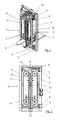
- Fig. 1 shows an apparatus for processing a band- or plate-shaped metal workpiece 1 (in Fig. 3 and Fig. 6 exemplified).
- the device according to the invention is particularly suitable for removing the oxide layer from cut surfaces 1b and / or cut edges 1a of the workpieces 1.
- Both circumferential cut surfaces 1b and cut edges 1a of the workpiece 1 and cut surfaces 1b and cut edges 1a of recesses, holes or the like can be used the workpiece 1 are descaled. In experiments, it has been found that small holes generally do not have to be descaled, since they usually serve as screw holes and therefore painting or galvanizing is not absolutely necessary.
- workpieces 1 can be cleaned so advantageously of oxide layers or of impurities on the two main surfaces 1c or the surface of the workpiece 1 that a reliable and permanent coating or galvanizing is possible without a later spalling of the applied layer must be feared.
- the device according to the invention has two conveyor devices 2, which are each provided with brushes 3.
- the conveyors 2 guide the brushes 3 at least approximately linearly in the area of the workpiece 1 to be machined.
- the workpiece 1 to be machined is carried out or pulled through transversely to the direction of rotation of the conveyors 2 between the two conveyors 2.
- the inventive Device a guide channel 4, which also off Fig. 3 it is apparent.
- the guide channel 4 can be adjusted by means of an adjusting device 5.
- the device according to the invention has a sheet metal insert 6, through which the workpiece 1 can be introduced into the guide channel 4. After passing through the guide channel 4 or after passing through the two conveyors 2, the workpiece 1 is discharged onto a storage table 7. To push through the workpiece 1, a push plate or the next subsequent workpiece 1 may be provided.
- the delivery table 7 can have a vertical stop, which ensures that the workpiece 1 after delivery from the guide channel 4 in a defined direction can fall or be folded over (see Fig. 4 ).
- the guide channel 4 is also designed to guide the brushes 3 so that they are moved along the workpiece 1 in a defined manner and can not escape.
- the device according to the invention has an independent feed 8, by means of which the depth of engagement of the brushes 3 can be varied. This is particularly advantageous for correcting the wear of the brushes 3 or for increasing the pressure.
- these are moved to adjust the wear of the brush 3 to each other or adjusted.
- this is moved to a fixed wall of the guide channel 4, which serves as a counter-holder or as a replacement for the second conveyor 2 in this case, or adjusted.
- an adjustment of the guide channel 4 may be provided in the direction of the conveyor 2.
- the adjusting device 5 and the delivery 8 are formed with spindles.
- the spindles of the adjusting device 5 and the delivery 8 can be connected via a respective chain and provided with a worm gear.
- the conveyors 2 are arranged slightly offset from one another in the direction of passage of the workpiece 1.
- the offset in the direction of passage may be, for example, 10 to 100 mm, preferably 30 mm.
- the solution according to the invention in a manner not shown, be provided with horizontally arranged conveyors 2, so that the brushes 3 are arranged in the region of the workpiece 1 extending substantially horizontally.
- the direction of rotation of the conveyors 2 is selected such that the brushes 3 of both conveyors 2 in the same direction on the two main surfaces 1c of the workpiece are fed past.
- the direction of rotation of the conveyors 2 is, as out Fig. 2 can be seen, selected such that the brushes 3 from top to bottom or toward a in Fig. 4 shown bottom plate 9 are guided past the workpiece 1.
- This running direction results in a particularly advantageous removal of dirt and high stability Device according to the invention and the workpiece to be machined 1, as this is not uncontrolled moved by the brushes 3, but is pressed firmly and stably on the bottom plate 9.
- the direction of rotation of the conveyors 2 is selected such that the brushes 3 along the workpiece 1 in the direction of a boundary plate, which the workpiece 1 at a Front side leads, are passable. Analogous to the contact pressure of the workpiece 1 on the bottom plate 9 in the stationary embodiment of the conveyors 2, the workpiece 1 is thus pressed stably on the boundary plate.
- the second and third conveying means 2 in the direction of passage of the workpiece 1 consequently run in such a way that they are in contact therewith arranged brush 3 in the region of the workpiece 1 to move in opposite directions to the first and the fourth conveyor.
- This arrangement ensures that the workpiece 1 is pressed by the first conveyor 2 down in the direction of the bottom plate 9, the two next conveyors 2 press the workpiece 1 while upwards, this immediately by the subsequent fourth conveyor 2, which presses the workpiece 1 down again, is corrected.
- the first and the third conveyor as well as the second and the fourth conveyor are arranged on one side of the workpiece 1 or on a main surface 1c.
- Fig. 1 to Fig. 5 illustrated embodiment of the device according to the invention with two conveyors 2, it may be necessary that the workpiece 1 is reversed and pushed through again. This is when looking at the Fig. 6 simply conceivable, since the brush 3 of course facing the direction of rotation Sand side surfaces 1b and side edges 1a better than the side surfaces 1b and side edges 1a, which are oppositely oriented (so to speak, in the "slipstream" lie).
- Fig. 18 illustrated variant of the solution according to the invention with four conveyors 2, in which each two conveyors 2 brush to the right and two to the left, turning over and re-pushing the workpiece 1 is not necessary.
- the workpiece is finished with a single push through.
- an automatic feed for carrying out the workpieces 1 can be provided.
- Fig. 5 shows the device according to the invention with a housing 11.
- Both the sheet metal insert 6 and the storage table 7 can be designed to be height adjustable. It can also be provided that the width of the sheet metal insert 6 and / or the tray table 7 is adjustable.
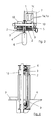
- the bristles 12 are in a simplified Presentation straight running. In an advantageous embodiment, however, it can be provided that the bristles 12 are corrugated or rotated, so that the bundles 120 formed by the bristles 12 resemble a scrubby brush or a tuft.
- the conveyor 2 is provided with a V-belt 13.
- V-belt 13 may also be a toothed belt, a flat belt with knobs, a chain, a belt or the like may be provided.
- the V-belt 13 is formed in the illustrated embodiment as a "triple" V-belt 13 with two outer V-belts 13b, 13c and a central V-belt 13a.
- the middle V-belt 13 a is provided for receiving the brushes 3.
- the V-belt 13 may be formed of rubber, plastic, synthetic rubber or preferably neoprene. It can generally be provided that the brushes 3 or the bristles 12 are glued, cast, bolted, punched or welded to the V-belt 13. In the exemplary embodiment, it is provided that a PU cover layer (polyurethane) 14 is applied to the V-belt 13.
- a support 15 preferably formed of rubber or plastic (e.g., neoprene) for the brush 3 and the bristles 12, respectively, can be easily welded. The result is an advantageous and reliable connection.
- the PU layer 14 may have a thickness of 1 to 5 mm, preferably 2 mm.
- the V-belt 13 can with several individual brushes 3 ( Fig. 6 ) or with a single V-belt 13 completely covering brush 3 ( Fig. 17 ) be provided.
- the bristles 12 can be shot in bundles 120 in the carrier 15.
- a secure and reliable connection of both the carrier 15 with the V-belt 13 and between the carrier 15 and the shot bundles 120 is ensured.
- a reliable connection is essential due to the high number of revolutions and the forces involved. As a result, high brushing speeds can be used.
- the design of the conveyor 2 as a belt drive with a V-belt 13 is smooth and reliable.
- the bristles 12 may be provided with not shown barbs.
- the V-belt 13 is formed in the embodiment as a so-called power band. It has been found in experiments that the outer two V-belts 13b, 13c sufficient to drive, so that the central V-belt 13a can be easily used to accommodate the bristles 12.
- the carrier 15 is provided transversely to the direction of rotation of the conveyor 2 and the V-belt 13 with slots 16.
- the carrier 15 in a manner not shown, also be formed of individual segments in similar dimensions. It can be provided that 16 portions 15a of the carrier 15 are formed by the slots, which have a length of 10 to 40 mm. In the exemplary embodiment, it is provided that both the length and the width of the sections 15a is 18 mm.
- Each section 15 a takes on a bundle 120 of the Bosten 12. Each form three sections 15a together, a brush 3. Of course, here are other combinations conceivable, for example, two or four sections 15a taken together can form a complete brush 3.
- the number of bristles 12 per bundle 120 is not limited to the illustrated number, but it is intended to combine a plurality of bristles into a bundle 120.
- the carrier 15 is divided by the slots 16 into sections 15a, results in a particularly small bending radius, so that the entire device can be made to save space and cost.
- the length of the bristles 12 is 30 to 90 mm, preferably 60 mm.
- the carrier 15 may be formed of the same material as the V-belt 13. In this case, various embodiments are conceivable which are suitable for shooting in the bristles 12 are and can be reliably welded to the PU cover layer 14.
- FIGS. 10a to 10d Various advantageous embodiments of the V-belt 13 can be seen.
- the V-belts 13 according to Fig. 10a to Fig. 10d in this case have elevations or projections 17 on their upper side to be provided with the carrier 15, which are intended to guide or support the carrier 15.
- Fig. 10a in this case shows a triangular-shaped projection 17 in cross-section, which runs parallel to the central V-belt 13a.
- carrier 15 in this case preferably has a projection 17 corresponding recess, whereby a particularly reliable connection between the carrier 15 and the belt 13 is formed.
- Fig. 10b shows a particularly preferred embodiment of the V-belt 13, which also in Fig. 11 is shown.
- the V-belt 13 according to Fig. 10b in this case has two projections 17, which laterally guide or support the carrier 15.
- the width of the carrier 15 and the distances between the projections 17 are preferably matched to one another.
- Fig. 10c shows one too Fig. 10a alternative embodiment of the projection 17, which also extends parallel to the central V-belt 13a.
- a groove / spring connection between the carrier 15 and the V-belt 13 is provided.
- Fig. 10d shows one too Fig. 10b simplified design of the V-belt 13, in which the carrier 15 only at one Side is guided or stabilized by a projection 17. As has been found in experiments, already sufficient lateral projection to achieve an improvement in the connection between the carrier 15 and the belt 13.
- the projections 17 according to the FIGS. 10a to 10d advantageously prevent rotation or rotational movement of the carrier 15.
- FIGS. 10a to 10d shown V-belt shapes can be easily and inexpensively manufactured and provide an additional positive connection of the carrier 15 with the V-belt 13th
- Fig. 11 shows the V-belt 13 on which a preferably made of rubber or plastic carrier 15 is screwed, riveted, glued, welded or clipped.
- the carrier 15, which serves to receive the brush 3 or the bristles 12, is composed of segments 15b, two of which are exemplified in FIG Fig. 11 are shown.
- the distance between the segments 15b in the exemplary embodiment is 3 to 20 mm, preferably 6 to 10 mm.
- the segments 15b may be arranged without clearance or at a greater distance.
- Fig. 12 shows an advantageous embodiment of the segments 15b.
- the segments 15b each have at one end a groove 18 and at the other end a spring 19, by means of which the segments 15b are connectable to each other. A rotation of the segments 15b is prevented by the groove / spring connection in a simple and advantageous manner.
- the segments 15b are for clarity in 11 and FIG. 12 shown without inserted bristles 12.
- Fig. 13 shows a segment 15b and a portion 15a of a carrier 15 with inserted bristles 12.
- the bristles 12 of the brush 3 are at most up to 45 °, preferably inclined by 15 ° in the direction of rotation. That is, the tips of the bristles 12 are in the direction of rotation in front of the correspondingly opposite end of the bristles, which is connected to the carrier 15.
- an inclination of the bristles beyond 45 ° is also possible, however, this possibly leads to tilting and damage to the bristles 12 when they penetrate into the recesses of the workpiece 1.
- Fig. 14 shows a modification of the in Fig. 13
- the support bristle 20 stabilizes the inclined bristles 12 and thus improves the penetration in recesses of the workpiece 1 or ensures a uniform descaling.
- the support bristle 20 is shorter than the bristles 12.
- a vertical or rectangular arrangement of the support bristle 20 relative to the surface of the support 15 or the surface of the segments 15b is advantageous for stabilizing or supporting the bristles 12 exposed.
- the compound of the support bristle 20 with the Carrier 15 can be carried out analogously to the connection of the bristles 12 to the carrier 15.
- bristles 12 of the brush 3 may be formed in an advantageous manner as roped bristles and / or abrasive bristles. This has been found in experiments to be particularly suitable.
- Fig. 15 shows a segment 15b of the carrier 15 with a bundle 120 of the bristles 12, which is surrounded by a jacket 21 stabilizing or supporting.
- the sheath 21 serves as an alternative to the use of support bristles 20.
- the sheath 21 extends as in Fig. 15 from the lower end of the bristles 12 to approximately the middle of the bristles 12. This has been found to be particularly suitable for stabilization, without the risk that the sheath in contact with the workpiece 1 device.
- Fig. 16 shows a V-belt 13 with an array of segments 15b according to Fig. 11 , wherein the segments 15b with 15 ° inclined bristles 12 according to Fig. 13 are provided. This is a particularly preferred embodiment.
- Fig. 17 shows a section of a conveyor 2 in the direction of rotation after a deflection point 22 before the brush 3 and the bristles 12 come back into contact with the band or plate-shaped metal workpiece 1.
- a resistance element 23 is arranged in this area.
- the deflection point 22 is for clarity in Fig. 2 shown. Under deflection 22 is the place to understand in which the V-belt 13, is deflected due to the rollers, rollers or the like driving the V-belt 13. The direction in which the V-belt 13 moves is opposite before or after the deflection point 22.
- the inventor has found out in a non-obvious way that the bristles 12 buckle in the direction of rotation after the deflection point 22 and later erect again in the intended manner, preferably 15 ° inclined.
- the buckling of the bristles 12 takes place in the region in which the brush 3 or its bristles 12 leave the circular path of the deflection point 22 and move into a linear or straight-line movement.
- the buckling of the bristles 12 results essentially from the fact that the circular path of the deflection point 22 is left, the bristles 12, however, still bring a corresponding momentum, which leads to a bending movement to the front.
- the resistance element 23 may be formed mechanically as a steel roll, which can be introduced into the path of the brush 3 in such a way that the tips of the bristles 12 strike against it and thereby break the momentum causing the buckling of the bristles 12.
- the steel roller 23 can, as in Fig. 17 shown, on a plate 24 may be arranged, which in turn is preferably pivotally mounted on a (not shown) fixed housing part.
- the steel roller can 23 with the plate 24 are easily placed on the tips of the bristles 12, wherein the weight of the steel roller 23 and the plate 24 is sufficient for pressing.
- the necessary contact pressure can be generated in a simple manner, for example via springs, not shown, in a simple manner.
- the resistance element 23 may also be formed as a magnet which is arranged in the region of the deflection point 22 such that buckling of the bristles 12 is prevented by the magnetic force of the magnet.
- Fig. 18 shows a particularly preferred embodiment of the device according to the invention with four conveyors 2.
- the preferred arrangement of the conveyors 2 in terms their direction of circulation has already been dealt with above.
- Fig. 18 shows the device according to the invention only schematically, wherein the representation has been reduced to the parts essential to the invention.
- Fig. 18 shows the device according to the invention in a horizontal state, ie, the workpiece 1 is placed horizontally and pushed through.
- a sheet metal insert 6 is used to output the workpiece 1
- a tray table 7 is provided between the second and the third conveyor 2 there is a bottom plate 9, which serves to stably pass the workpiece 1 through the device.
- the sheet tray 6, the tray table 7 and the bottom plate 9 are in the in Fig. 18 Embodiment shown formed as a table elements whose parallel to the feed direction of the workpiece 1 extending side edges are formed as a perforated plate for receiving rollers 25 and rollers. Because the table elements 6, 7, 9 are provided with a roller system, the workpiece 1 can be pushed through the device in a particularly simple manner transversely to the conveyor devices 2. In contrast to a rubber conveyor belt, the roller system is much more robust and unsusceptible to damage caused by tilting of the workpiece 1.
- the in Fig. 18 illustrated apparatus also three feed rollers 26.
- the feed rollers 26 are made in the embodiment from a metallic base body, which is provided with a rubber coating.
- the rubber coating on a profile or a corrugation for example, a cross pattern on.
- other patterns such as those known from tire profiles, can be used.
- the casing of the main body of the feed roller 26 may be made of rubber or plastic.
- a brush guide 27 is arranged to prevent the brushes 3, due to the feed movement of the workpiece 1, to bend backwards or be moved.
- a brush guide 27 is in a special way a sliding plastic, especially an abrasion-resistant plastic, such as the designated as S green special plastic.
- Fig. 18 For reasons of simplification, is in Fig. 18 neither the belt nor a motor shown. Shown, however, is a carrier 29 for the engine and the belt. By the in Fig. 18 illustrated solution according to the invention with four conveyors 2, it is possible to work the workpiece 1 in one go completely. A re-insertion of the workpiece 1 is not necessary.
- the speed at which the brush 3 or the bristles 12 are guided along the workpiece 1 is preferably 15 to 16 m / sec.
- FIG. 18 The embodiment shown in FIGS. 1 to 5 described standing embodiment of the device according to the invention.
- the solution according to the invention can be produced with different processing lengths or different widths for the import of workpieces 1.
Description
Die Erfindung betrifft eine Vorrichtung sowie ein Verfahren zum Bearbeiten eines band- oder plattenförmigen metallischen Werkstückes, insbesondere zum Entfernen der Oxidschicht von Schnittflächen und/oder Schnittkanten des Werkstückes.The invention relates to a device and a method for processing a band-shaped or plate-shaped metallic workpiece, in particular for removing the oxide layer of cut surfaces and / or cut edges of the workpiece.
Eine Vorrichtung und ein Verfahren zum Bearbeiten eines Metallbandes ist aus der
Beim Laserschneiden von metallischen Werkstücken bildet sich an den Schnittkanten sowie an den Schnittflächen eine Oxidschicht bzw. eine Oxidhaut. Von Nachteil bei der Oxidschicht ist, dass eine darauf aufgetragene Lackierung oder Verzinkung relativ schnell wieder abspringt. Aus diesem Grund werden die metallischen Werkstücke vor dem Lackieren und Verzinken abgeschliffen.In the laser cutting of metallic workpieces, an oxide layer or an oxide skin is formed at the cut edges and at the cut surfaces. A disadvantage of the oxide layer is that a paint or zinc coating applied to it bounces off relatively quickly. For this reason, the metallic workpieces are ground off before painting and galvanizing.
Von Nachteil beim Abschleifen der Schnittflächen bzw. Schnittkanten, d.h. beim Entfernen der Oxidschicht von denselben - dieser Vorgang wird auch als Entzundern bezeichnet - ist, dass dadurch die Schnittkanten geschärft werden, woraus eine erhöhte Verletzungsgefahr resultiert. Die Schnittkanten müssen deshalb nach dem Schleifen gegebenenfalls wieder entschärft werden.A disadvantage when grinding the cut surfaces or cut edges, i. When removing the oxide layer of the same - this process is also referred to as descaling - is that this sharpened the cutting edges, resulting in an increased risk of injury results. The cut edges must therefore be defused again after grinding if necessary.
Die gattungsgemäße Schrift zeigt ein Verfahren und eine Vorrichtung zum Entfernen der Oxidhaut an Metallzuschnitten. Der Metallzuschnitt wird dabei zum Abtragen der Oxidschicht von den Schnittflächen zwischen paarig angeordnete, rotierende, spanende Bearbeitungswerkzeuge hindurchgeführt. Durch dieses Verfahren lassen sich zwar die außenliegenden Schnittflächen von der Oxidschicht reinigen, jedoch ist eine Entfernung der Oxidschicht von innenliegenden Schnittflächen, z.B. von Aussparungen oder ähnlichen Durchbrüchen des Werkstückes nicht möglich. Darüber hinaus muss der Metallzuschnitt einer weiteren Bearbeitungsvorrichtung zugeführt werden, falls auch die Oberfläche bzw. die Hauptfläche des Werkstücks gesäubert bzw. gereinigt werden soll.The generic document shows a method and apparatus for removing the oxide skin on metal blanks. The metal blank is used to remove the oxide layer passed from the cut surfaces between paired, rotating, machining tools. Although the outer cut surfaces of the oxide layer can be cleaned by this method, it is not possible to remove the oxide layer from inner cut surfaces, for example from recesses or similar openings in the workpiece. In addition, the metal blank must be fed to a further processing device, if the surface or the main surface of the workpiece to be cleaned or cleaned.
Nachteilig bei der Vorrichtung der gattungsgemäßen Schrift ist außerdem die Handhabung, sowie der kostenintensive Aufbau und der hohe Platzbedarf. Darüber hinaus nutzen sich die Bearbeitungswerkzeuge ungleich ab, da im Regelfall davon auszugehen ist, dass die zu entzundernden Metallzuschnitte immer im selben Bereich, d.h. an derselben Stelle, eingeschoben werden, so dass ein Teil des Bearbeitungswerkzeuges nie in Kontakt mit dem Metallzuschnitt kommt, während ein anderer Teil des Bearbeitungswerkzeugs einer permanenten Abnutzung unterliegt.A disadvantage of the device of the generic document is also the handling, and the cost-intensive design and high space requirements. In addition, the processing tools use uneven, since it is generally assumed that the metal blanks to be descaled always in the same area, i. in the same place, so that one part of the machining tool never comes into contact with the metal blank, while another part of the machining tool is subject to permanent wear.
Aus dem allgemeinen Stand der Technik sind ferner Vorrichtungen zum Entgraten und Feinschleifen bekannt. Hierbei werden sowohl Walzen als auch tellerförmige, rotierende Bürstenwerkzeuge eingesetzt. Bei den bekannten Vorrichtungen wird das zu bearbeitende Werkstück auf einer horizontalen Arbeitsebene oder einem Förderband aufgelegt und unter der Walze oder dem rotierenden Bürstenwerkzeug von Hand oder automatisch durchgeführt. Wie auch bei der in der gattungsgemäßen Schrift beschriebenen Vorrichtung besteht der Nachteil, dass im allgemeinen die Werkstücke immer an derselben Stelle eingeschoben werden, so dass eine ungleiche Abnützung der Walze oder der Bürstenwerkzeuge erfolgt. Derartige Maschinen können beispielsweise eine Arbeitsbreite von 1 bis 2 m aufweisen, werden jedoch in der Praxis zumeist mit kleineren Metallzuschnitten bestückt. Dies hat zur Folge, dass eine Walze mit beispielsweise 2 m Länge lediglich auf den ersten 50 cm ihrer Länge von Metallzuschnitten beansprucht wird und sich somit nur in diesem Bereich abnützt. Die Walze muss, sobald dieser Bereich zu weit abgenutzt ist, ausgetauscht werden, obwohl drei Viertel der Walzenfläche noch gut erhalten und brauchbar ist. Ein Austausch ist schon deshalb nicht zu vermeiden, da beim Einbringen eines großen Werkstückes nunmehr die ersten 50 cm der Walze nicht mehr schleifen. Durch die ungleiche Abnützung der Walze und dem daraus resultierenden unterschiedlichen Druck auf das Werkstück ergeben sich minderwertige Schleifergebnisse. Auf die Qualität der Entgratung bzw. des Schleifens wirkt sich außerdem negativ aus, dass die Bürste bzw. die Walze nicht stufenlos in ihrer Eindringtiefe verstellbar ist. Ein an sich sinnvolles, tiefes Eindringen der Borsten wird durch das Förderband, auf dem das Werkstück liegt, verhindert, da dieses nicht beschädigt werden sollte.Devices for deburring and fine grinding are also known from the general state of the art. Here, both rollers and plate-shaped, rotating brush tools are used. In the known devices, the workpiece to be machined is placed on a horizontal working plane or a conveyor belt and performed under the roller or the rotary brush tool by hand or automatically. As with the device described in the generic document has the disadvantage that in general the workpieces always on the same Place be inserted so that an uneven wear of the roller or the brush tools. Such machines can for example have a working width of 1 to 2 m, but in practice usually equipped with smaller metal blanks. This has the consequence that a roll with for example 2 m in length is only claimed on the first 50 cm of its length of metal blanks and thus wears only in this area. The roller must be replaced as soon as this area is worn out too much, although three quarters of the roller surface is still well preserved and usable. An exchange is therefore unavoidable, since when introducing a large workpiece now no longer grind the first 50 cm of the roller. The uneven wear of the roller and the resulting different pressure on the workpiece result in inferior grinding results. On the quality of deburring or grinding also has a negative effect that the brush or the roller is not infinitely adjustable in their penetration depth. An inherently meaningful, deep penetration of the bristles is prevented by the conveyor belt on which the workpiece lies, as this should not be damaged.
Von Nachteil bei den bekannten Entgrat- und Schleifmaschinen ist außerdem, dass das Werkstück zweimal eingeführt werden muss, damit beide Hauptflächen des Werkstückes bearbeitet werden können. Ein weiterer Nachteil der bekannten Maschinen ist die hohe Antriebsleistung, der hohe Platzbedarf sowie die hohen Anschaffungs- und Instandhaltungskosten. Die Grundflächen der Maschinen sind so dimensioniert, dass auch maximal große Werkstücke flächig eingeschoben und bearbeitet werden können. Dies hat zur Folge, dass, wenn die Maschine für die Bearbeitung von 2 x 2 m großen Metallstücken vorgesehen ist, die Grundfläche mindestens einen derartigen Platzbedarf benötigt. Hinzu kommt der Platz, der zum Auflegen und Ausrichten des Metallstückes vor dem Einschieben in die Maschine sowie zur Entnahme benötigt wird.A disadvantage of the known deburring and grinding machines is also that the workpiece must be inserted twice so that both main surfaces of the workpiece can be edited. Another disadvantage of the known machines is the high drive power, the high space requirement and the high acquisition and maintenance costs. The basic surfaces of the machines are dimensioned so that even the largest workpieces can be inserted and processed flat. As a result, when the machine is intended for the processing of 2 x 2 m large pieces of metal, the base requires at least such a space requirement. Added to this is the space required for placing and aligning the piece of metal prior to insertion into the machine and for removal.
Von Nachteil bei den bekannten Schleifmaschinen ist außerdem, dass diese entweder dazu geeignet sind, die Hauptflächen des Werkstückes zu säubern bzw. fein zu schleifen oder sich, wie die Vorrichtung der gattungsgemäße Schrift, zum Entzundern des umlaufenden Randes des Werkstückes eignen. Darüber hinaus sind, abgesehen von einer Handbearbeitung, keine Lösungen bekannt, die innenliegende Aussparungen, Löcher, Durchbrüche und dergleichen entzundern.Another disadvantage of the known grinding machines is that they are either suitable for cleaning or finely grinding the main surfaces of the workpiece or, like the device of the generic type, for descaling the peripheral edge of the workpiece. Moreover, apart from manual processing, no solutions are known which desalinate internal recesses, holes, apertures and the like.
Aus dem Stand der Technik sind ferner teure und aufwändige Nassschleifverfahren bekannt.Furthermore, expensive and expensive wet grinding methods are known from the prior art.
Aus der
Aus der
Aus der
Der vorliegenden Erfindung liegt die Aufgabe zugrunde, die vorgenannten Nachteile des Standes der Technik zu lösen, insbesondere eine schnelle, einfache und kostengünstige Vorrichtung und ein Verfahren zum Bearbeiten von band- oder plattenförmigen metallischen Werkstücken, insbesondere zum Entfernen der Oxidschicht von Schnittflächen und/oder Schnittkanten derselben zu schaffen.The present invention has for its object to solve the above-mentioned disadvantages of the prior art, in particular a fast, simple and inexpensive device and a method for processing strip or plate-shaped metallic workpieces, in particular for removing the oxide layer of cut surfaces and / or cut edges to create the same.
Diese Aufgabe wird erfindungsgemäß durch Anspruch 1 gelöst.This object is achieved by
Ein Verfahren zum Bearbeiten eines metallischen Werkstücks ergibt sich aus Anspruch 35.A method for processing a metallic workpiece results from claim 35.
Da die Bürste aufgrund der Anordnung an einer umlaufenden Fördereinrichtung nicht starr auf einer Position verharrt, sondern auf der ganzen Länge, die zur Durchführung des Werkstücks vorhanden ist, vorbeigeführt wird, ist eine gleichmäßige Abnutzung der wenigstens einen Bürste gewährleistet. Das Werkstück kann dabei in einfacher Weise schräg, vorzugsweise quer zur Umlaufrichtung der Bürste durchgeführt bzw. durchgezogen werden, so dass das Werkstück gleichmäßig von der Bürste bearbeitet wird.Since the brush does not remain rigidly in one position due to the arrangement on a circulating conveyor, but is guided along the entire length which is present for the passage of the workpiece, a uniform wear of the at least one brush is ensured. The workpiece can be carried out in a simple manner obliquely, preferably transversely to the direction of rotation of the brush or pulled through, so that the workpiece is processed uniformly by the brush.
Aufgrund des linearen Verlaufes der Bürste im Bereich des zu bearbeitenden Werkstücks ist, wie der Erfinder in überraschender Weise festgestellt hat, sichergestellt, dass die Bürste in alle Aussparungen oder Löcher des Werkstückes eindringt und somit die Oxidschicht an allen Schnittflächen und Schnittkanten entfernt. Die Bürste fährt somit schräg bzw. quer zur Vorschubrichtung des Werkstücks auf dem Werkstück entlang und dringt, ähnlich wie ein Pinsel, der auf einem Metallstück entlanggezogen wird, in jede Aussparung ein.Due to the linear course of the brush in the region of the workpiece to be machined, as the inventor has surprisingly found, ensures that the brush penetrates into all recesses or holes of the workpiece and thus the oxide layer at all cutting surfaces and Cut edges removed. The brush thus moves obliquely or transversely to the feed direction of the workpiece along the workpiece and, similar to a brush, which is pulled along on a metal piece, penetrates into each recess.
In vorteilhafter Weise werden mit der erfindungsgemäßen Vorrichtung sowohl die Oberflächen, d.h. die Hauptflächen der band- oder plattenförmigen metallischen Werkstücke bearbeitet, als auch die Schnittflächen und Schnittkanten entzundert. Ein gleichzeitiges Entzundern der Schnittflächen und Schnittkanten sowie eine Reinigung der Oberflächen war mit den bisher bekannten Vorrichtungen nicht möglich.Advantageously, with the device according to the invention both the surfaces, i. the main surfaces of the band- or plate-shaped metal workpieces machined, as well as the cut surfaces and cut edges descaled. Simultaneous descaling of the cut surfaces and cut edges and cleaning of the surfaces was not possible with the previously known devices.
Von Vorteil ist es, wenn zwei Fördereinrichtungen vorgesehen sind, zwischen denen das Werkstück schräg bzw. quer zur Umlaufrichtung derart durchführbar ist, dass jede Fördereinrichtung mit den zugeordneten Bürsten eine der beiden Hauptflächen des Werkstückes bearbeitet.It is advantageous if two conveyors are provided, between which the workpiece obliquely or transversely to the direction of rotation is feasible such that each conveyor with the associated brushes processed one of the two main surfaces of the workpiece.
In besonders vorteilhafter Weise werden dadurch mit einem Arbeitsgang beide Hauptflächen des Werkstückes bearbeitet. Außerdem werden die Schnittkanten sowie die Schnittflächen von beiden Seiten bearbeitet, so dass eine besonders gründliche Entzunderung erfolgt. Der Einsatz von zwei Fördereinrichtungen ermöglicht ein schnelles und rationales Bearbeiten des Werkstückes.In a particularly advantageous manner, both main surfaces of the workpiece are thereby processed with one operation. In addition, the cut edges and the cut surfaces are processed from both sides, so that a very thorough descaling takes place. The use of two conveyors allows a fast and rational machining of the workpiece.
Erfindungsgemäß kann ferner vorgesehen sein, dass die Fördereinrichtungen mehrere auf Abstand zueinander angeordnete Bürsten aufweisen.According to the invention, it can further be provided that the conveying devices have a plurality of brushes arranged at a distance from one another.
Wie der Erfinder in nicht naheliegender Weise festgestellt hat, ergibt sich, wenn die Fördereinrichtung mehrere auf Abstand zueinander angeordnete Bürsten aufweist, eine besonders hochwertige und zuverlässige Bearbeitung der Hauptflächen des Werkstückes sowie der Schnittflächen und Schnittkanten. Dadurch, dass ein Abstand zwischen den Bürsten vorhanden ist, wird vermieden, dass die in Umlaufrichtung vorne liegenden Borsten der Bürsten die nachfolgenden bereits umgebogen haben, bevor diese das Werkstück erreichen. Dies war bei den aus dem Stand der Technik bekannten Bürsten der Fall (beispielsweise bei der rotierenden "Tellerbürste"). Wenn die nachfolgenden Borsten durch die vorauslaufenden Borsten bereits umgebogen sind, können die nachfolgenden Borsten nicht mehr weit genug in Aussparungen und dergleichen eindringen, so dass diese nur unzureichend gereinigt werden.As the inventor has found out in a non-obvious manner, when the conveyor has a plurality of spaced apart brushes, a particularly high-quality and reliable machining of the main surfaces of the workpiece and the cut surfaces and edges. The fact that a distance between the brushes is present, it is avoided that the front lying in the direction of rotation bristles of the brushes have already bent before they reach the workpiece. This was the case with the brushes known from the prior art (for example, in the rotating "plate brush"). If the subsequent bristles are already bent over by the leading bristles, the following bristles can no longer penetrate far enough into recesses and the like, so that they are only insufficiently cleaned.
Durch den Abstand zwischen den Bürsten ist sichergestellt, dass die Bürsten jeweils ungebogen auf das Werkstück treffen bzw. vorteilhaft in Aussparungen oder Löcher eindringen.The distance between the brushes ensures that the brushes each hit unbelted on the workpiece or advantageously penetrate into recesses or holes.
In einer Weiterbildung der Erfindung kann vorgesehen sein, dass die Borsten gewellt und/oder gedreht ausgebildet sind.In one embodiment of the invention can be provided that the bristles are corrugated and / or formed rotated.
Durch eine gewellte Ausbildung der Borsten der Bürsten ist sichergestellt, dass die Borsten nicht gleichmäßig in Reihe, sondern unregelmäßig angeordnet sind, so dass die Borsten zum einen durch in Umlaufrichtung vorne liegende Borsten wenig beeinträchtigt werden und sich zum anderen, wie sich überraschend in Versuchen herausgestellt hat, eine qualitativ besonders hochwertige Reinigung erreichen lässt. Vorteilhafte Ausgestaltungen und Weiterbildungen der Erfindung ergeben sich aus den weiteren Unteransprüchen und aus den nachfolgend anhand der Zeichnung prinzipmäßig dargestellten Ausführungsbeispielen.By a corrugated design of the bristles of the brushes ensures that the bristles are not arranged uniformly in series, but irregular, so that the bristles are on the one hand little affected by lying in the direction of rotation bristles front and on the other, as emerges surprisingly in experiments has achieved a particularly high quality cleaning. Advantageous embodiments and modifications of the invention will become apparent from the other dependent claims and from the embodiments illustrated in principle below with reference to the drawing.
Aus Anspruch 31 ergibt sich ein besonders vorteilhafter Keilriemen und aus Anspruch 32 ein vorteilhafter Träger mit Borsten zum Einsetzen in die erfindungsgemäße Vorrichtung.From claim 31 results in a particularly advantageous V-belt and from claim 32 an advantageous carrier with bristles for insertion into the device according to the invention.
Es zeigt:
- Fig. 1
- eine perspektivische Darstellung der erfindungsgemäßen Vorrichtung mit zwei Fördereinrichtungen;
- Fig. 2
- eine Vorderansicht der erfindungsgemäßen Vorrichtung gemäß
Fig. 1 mit zwei Fördereinrichtungen; - Fig. 3
- eine Draufsicht auf die erfindungsgemäße Vorrichtung gemäß Pfeilrichtung III der
Fig. 2 ; - Fig. 4
- eine Seitenansicht der erfindungsgemäßen Vorrichtung gemäß Pfeilrichtung IV der
Fig. 2 ; - Fig. 5
- eine perspektivische Darstellung der erfindungsgemäßen Vorrichtung mit einem Gehäuse;
- Fig. 6
- eine Prinzipdarstellung eines zu bearbeitenden Werkstücks und einer im wesentlichen vertikal verlaufenden Fördereinrichtung mit mehreren jeweils auf Trägern angeordneten Bürsten;
- Fig. 7
- eine perspektivische Darstellung eines Ausschnitts eines Keilriemens mit einem Träger und eingeschossenen Borsten;
- Fig. 8
- eine Ansicht eines Teiles eines Keilriemens gemäß Pfeilrichtung VIII der
Fig. 7 ; - Fig. 9
- eine Draufsicht auf einen Teil eines Keilriemens gemäß Pfeilrichtung IX der
Fig. 8 ; - Fig. 10a bis 10d
- verschiedene Ausführungsformen des Keilriemens;
- Fig. 11
- eine perspektivische Darstellung eines Ausschnitts eines Keilriemens mit einer Ausbildung des Trägers aus freistehend angeordneten Segmenten;
- Fig. 12
- eine perspektivische Darstellung von einzelnen Segmenten des Trägers, wobei die Segmente mittels einer Nut/Feder-Verbindung zusammensteckbar sind;
- Fig. 13
- eine Seitenansicht eines Segments des Trägers mit schräg gestellten Borsten;
- Fig. 14
- eine Seitenansicht eines Segments des Trägers mit schräg gestellten Borsten und einem stabilisierenden Stützborsten;
- Fig. 15
- eine perspektivische Darstellung eines Segments des Trägers mit einem Bündel von Borsten und einer stabilisierenden Ummantelung;
- Fig. 16
- eine perspektivische Darstellung eines Ausschnitts eines Keilriemens in einer zu
Fig. 7 alternativen Ausführungsform mit freistehend angeordneten Segmenten, die mit schräg stehenden Borsten versehenen sind; - Fig. 17
- ein Ausschnitt der Fördereinrichtung in Umlaufrichtung nach einer Umlenkstelle mit einem als Stahlrolle ausgebildeten Widerstandselement; und
- Fig. 18
- eine Seitenansicht der erfindungsgemäßen Vorrichtung mit vier im wesentlichen horizontal verlaufenden Fördereinrichtungen.
- Fig. 1
- a perspective view of the device according to the invention with two conveyors;
- Fig. 2
- a front view of the device according to the invention according to
Fig. 1 with two conveyors; - Fig. 3
- a plan view of the device according to the invention in the direction of arrow III of
Fig. 2 ; - Fig. 4
- a side view of the device according to the invention in the direction of arrow IV of
Fig. 2 ; - Fig. 5
- a perspective view of the device according to the invention with a housing;
- Fig. 6
- a schematic representation of a workpiece to be machined and a substantially vertically extending conveyor with a plurality of each arranged on carriers brushes;
- Fig. 7
- a perspective view of a section of a V-belt with a carrier and shot bristles;
- Fig. 8
- a view of a part of a V-belt according to arrow VIII of the
Fig. 7 ; - Fig. 9
- a plan view of a part of a V-belt according to the direction of arrow IX of
Fig. 8 ; - Fig. 10a to 10d
- various embodiments of the V-belt;
- Fig. 11
- a perspective view of a section of a V-belt with a design of the carrier of freestanding arranged segments;
- Fig. 12
- a perspective view of individual segments of the carrier, wherein the segments are joined together by means of a tongue and groove connection;
- Fig. 13
- a side view of a segment of the carrier with inclined bristles;
- Fig. 14
- a side view of a segment of the carrier with inclined bristles and a stabilizing support bristles;
- Fig. 15
- a perspective view of a segment of the carrier with a bundle of bristles and a stabilizing sheath;
- Fig. 16
- a perspective view of a section of a V-belt in a to
Fig. 7 alternative embodiment with freestanding segments, which are provided with inclined bristles; - Fig. 17
- a section of the conveyor in the direction of rotation after a deflection with a designed as a steel roller resistance element; and
- Fig. 18
- a side view of the device according to the invention with four substantially horizontally extending conveyors.
Durch die erfindungsgemäße Vorrichtung können Werkstücke 1 so vorteilhaft von Oxidschichten bzw. von Verunreinigungen auf den beiden Hauptflächen 1c bzw. der Oberfläche des Werkstückes 1 gereinigt werden, dass eine zuverlässige und dauerhafte Lackierung bzw. Verzinkung möglich ist, ohne dass ein späteres Abplatzen der aufgetragenen Schicht befürchtet werden muss.By means of the device according to the invention,
Wie aus
In Abhängigkeit der Stärke des zu bearbeitenden Werkstückes 1 kann der Führungskanal 4 mittels einer Verstelleinrichtung 5 angepasst werden. Zum bequemen Durchführen des Werkstückes 1 weist die erfindungsgemäße Vorrichtung einen Blecheinschub 6 auf, durch den das Werkstück 1 in den Führungskanal 4 eingebracht werden kann. Nach Durchlaufen des Führungskanals 4 bzw. nach Durchlaufen der beiden Fördereinrichtungen 2 wird das Werkstück 1 auf einen Ablagetisch 7 ausgegeben. Zum Durchschieben des Werkstücks 1 kann ein Durchschubblech bzw. das nächste nachfolgende Werkstück 1 vorgesehen sein.Depending on the thickness of the
Der Ablagetisch 7 kann über einen vertikal verlaufenden Anschlag verfügen, der sicherstellt, dass das Werkstück 1 nach der Ausgabe aus dem Führungskanal 4 in eine definierte Richtung umfällt bzw. umgelegt werden kann (siehe
Der Führungskanal 4 ist auch zur Führung der Bürsten 3 ausgebildet, damit diese definiert entlang des Werkstücks 1 verfahren und nicht ausweichen können.The
Zusätzlich zu der Verstelleinrichtung 5 verfügt die erfindungsgemäße Vorrichtung über eine unabhängige Zustellung 8, mittels derer die Eingriffstiefe der Bürsten 3 variiert werden kann. Dies ist insbesondere zur Korrektur der Abnutzung der Bürsten 3 bzw. zur Erhöhung des Drucks vorteilhaft. Bei der im Ausführungsbeispiel dargestellten Variante mit zwei Fördereinrichtungen 2 werden diese zur Korrektur der Abnutzung der Bürste 3 zueinander verschoben bzw. verstellt. In einer besonders einfachen Ausgestaltung der erfindungsgemäßen Lösung, mit nur einer Fördereinrichtung 2, wird diese zu einer festen Wandung des Führungskanals 4, der in diesem Fall als Gegenhalter bzw. als Ersatz für die zweite Fördereinrichtung 2 dient, verschoben bzw. verstellt. Selbstverständlich kann in dieser Ausführungsform auch eine Verstellung des Führungskanals 4 in Richtung auf die Fördereinrichtung 2 vorgesehen sein.In addition to the
Im Ausführungsbeispiel ist vorgesehen, dass die Verstelleinrichtung 5 sowie die Zustellung 8 mit Spindeln ausgebildet sind. In nicht näher dargestellter Weise können die Spindeln der Verstelleinrichtung 5 bzw. der Zustellung 8 über jeweils eine Kette verbunden und mit einem Schneckengetriebe versehen sein.In the embodiment, it is provided that the adjusting
Wie aus
In einer nicht dargestellten Ausführungsform, bei der vier Fördereinrichtungen 2 vorgesehen sind, hat es sich ebenfalls als vorteilhaft herausgestellt, diese entsprechend versetzt anzuordnen.In an embodiment not shown, in which four
Bei der dargestellten erfindungsgemäßen Lösung handelt es sich um eine Variante, bei der die Fördereinrichtungen 2 stehend angeordnet sind, so dass die Bürsten 3 der Fördereinrichtung 2 im Bereich des Werkstückes im wesentlichen vertikal verlaufen.In the illustrated solution according to the invention is a variant in which the
Alternativ dazu kann die erfindungsgemäße Lösung, in nicht dargestellter Weise, mit liegend angeordneten Fördereinrichtungen 2 versehen sein, so dass die Bürsten 3 im Bereich des Werkstücks 1 im wesentlichen horizontal verlaufend angeordnet sind. Hierbei ist es zweckmäßig, die Spindeln der Verstelleinrichtung 5 bzw. der Zustellung 8, die das Gewicht der Vorrichtung im liegenden Zustand wenigstens teilweise aufnehmen müssen, durch Gegenrollenlager zu verstärken.Alternatively, the solution according to the invention, in a manner not shown, be provided with horizontally arranged
Im Ausführungsbeispiel gemäß
Die Umlaufrichtung der Fördereinrichtungen 2 ist, wie aus
In einer Variante der erfindungsgemäßen Vorrichtung, bei der die Fördereinrichtungen 2 liegend ausgebildet sind, ist es vorteilhaft, wenn die Umlaufrichtung der Fördereinrichtungen 2 derart gewählt ist, dass die Bürsten 3 entlang dem Werkstück 1 in Richtung auf eine Begrenzungsplatte, welche das Werkstück 1 an einer Stirnseite führt, vorbeiführbar sind. Analog zu der Anpressung des Werkstückes 1 auf die Bodenplatte 9 in der stehenden Ausgestaltung der Fördereinrichtungen 2 wird das Werkstück 1 somit stabil auf die Begrenzungsplatte gedrückt.In a variant of the device according to the invention, in which the
In Versuchen hat sich herausgestellt, dass es bei einer Ausgestaltung der erfindungsgemäßen Vorrichtung mit vier Fördereinrichtungen 2 vorteilhaft ist, wenn jede der beiden Hauptflächen 1c des Werkstücks 1 von jeweils zwei gegenläufig umlaufende Fördereinrichtungen 2 bearbeitet wird. Dabei ist es, um das Werkstück 1 besonders stabil und sicher durchführen zu können, vorteilhaft, wenn die Fördereinrichtungen 2, wie bereits beschrieben, in Durchlaufrichtung des Werkstückes 1 leicht versetzt zueinander angeordnet sind. Von Vorteil ist es dabei außerdem, wenn die Umlaufrichtungen derart gewählt werden, dass die Bürsten 3 der in Durchlaufrichtung des Werkstückes 1 ersten Fördereinrichtung 2 sowie der vierten Fördereinrichtung 2 in Richtung auf die Bodenplatte 9 an dem Werkstück 1 vorbeiführbar sind. Die in Durchlaufrichtung des Werkstücks 1 zweite und dritte Fördereinrichtung 2 verläuft folglich so, dass sich die darauf angeordneten Bürsten 3 im Bereich des Werkstückes 1 gegenläufig zu der ersten und der vierten Fördereinrichtung bewegen. Diese Anordnung stellt sicher, dass das Werkstück 1 durch die erste Fördereinrichtung 2 nach unten in Richtung auf die Bodenplatte 9 gedrückt wird, die beiden nächsten Fördereinrichtungen 2 drücken das Werkstück 1 zwar nach oben, wobei dies sofort wieder durch die sich anschließende vierte Fördereinrichtung 2, die das Werkstück 1 wieder nach unten drückt, korrigiert wird. Dabei sind jeweils die erste und die dritte Fördereinrichtung sowie die zweite und die vierte Fördereinrichtung auf einer Seite des Werkstückes 1 bzw. an einer Hauptfläche 1c angeordnet.In experiments it has been found that it is advantageous in an embodiment of the device according to the invention with four
Bei der liegenden Anordnung von vier Fördereinrichtungen 2 erfolgt die Auswahl der vorteilhaften Umlaufrichtungen der Fördereinrichtungen 2 analog, wobei die Bodenplatte 9 durch eine Begrenzungsplatte ersetzt ist.In the horizontal arrangement of four
In Versuchen hat sich herausgestellt, dass eine Umlaufgeschwindigkeit der Bürsten 3 von 5 bis 30 m/sek, vorzugsweise 15 bis 16 m/sek, besonders vorteilhaft ist. Diese Geschwindigkeit gewährleistet zum einen eine schnelle Bearbeitung der Werkstücke 1 und hat sich zum anderen hinsichtlich der Zuverlässigkeit der Bearbeitung und der Belastung der beteiligten Bauteile als geeignet herausgestellt.In experiments, it has been found that a circulation speed of the
Bei der gemäß
Bei der gemäß
In einer weiteren Variante der erfindungsgemäßen Lösung, die ebenfalls nicht dargestellt ist, kann ein automatischer Vorschub zur Durchführung der Werkstücke 1 vorgesehen sein.In a further variant of the solution according to the invention, which is likewise not shown, an automatic feed for carrying out the
In Versuchen hat sich herausgestellt, dass ein unabhängiger Antrieb für jede Fördereinrichtung 2 besonders zweckmäßig ist und darüber hinaus einfach und kostengünstig realisiert werden kann. Im Ausführungsbeispiel werden zum Antreiben der Fördereinrichtungen 2 Elektromotoren 10 verwendet.In experiments it has been found that an independent drive for each
Aus den
In dem Ausführungsbeispiel gemäß
Der Keilriemen 13 kann aus Gummi, Kunststoff, Kunstkautschuk oder vorzugsweise aus Neopren gebildet sein. Allgemein kann vorgesehen sein, dass die Bürsten 3 bzw. die Borsten 12 mit dem Keilriemen 13 verklebt, vergossen, verschraubt, verstanzt oder verschweißt sind. Im Ausführungsbeispiel ist vorgesehen, dass auf den Keilriemen 13 eine PU-Deckschicht (Polyurethan) 14 aufgebracht ist. Somit lässt sich ein vorzugsweise aus Gummi oder Kunststoff (z.B. Neopren) gebildeter Träger 15 für die Bürste 3 bzw. die Borsten 12 in einfacher Weise aufschweißen. Es entsteht eine vorteilhafte und zuverlässige Verbindung. Die PU-Schicht 14 kann eine Stärke von 1 bis 5 mm, vorzugsweise 2 mm, aufweisen.The V-
Der Keilriemen 13 kann mit mehreren einzelnen Bürsten 3 (
Die Borsten 12 können in Bündeln 120 in den Träger 15 eingeschossen werden. Eine sichere und zuverlässige Verbindung sowohl des Trägers 15 mit dem Keilriemen 13 als auch zwischen dem Träger 15 und den eingeschossenen Bündeln 120 ist sichergestellt. Eine zuverlässige Verbindung ist aufgrund der hohen Umdrehungszahl und der auftretenden Kräfte wesentlich. Resultierend daraus können hohe Bürstgeschwindigkeiten gefahren werden. Die Ausgestaltung der Fördereinrichtung 2 als Riemenantrieb mit einem Keilriemen 13 ist laufruhig und zuverlässig.The
Zum vorteilhaften Einschießen der Borsten 12 bzw. der Bündel 120 können die Borsten 12 mit nicht näher dargestellten Widerhaken versehen sein. Der Keilriemen 13 ist im Ausführungsbeispiel als sogenanntes Powerband ausgebildet. Dabei hat sich in Versuchen herausgestellt, dass die äußeren beiden Keilriemen 13b, 13c zum Antrieb ausreichen, so dass der mittlere Keilriemen 13a problemlos zur Aufnahme der Borsten 12 verwendet werden kann.For advantageous shooting of the
Wie sich aus den
Wie sich ebenfalls aus den
Dadurch, dass der Träger 15 durch die Schlitze 16 in Teilstücke 15a geteilt ist, ergibt sich ein besonders kleiner Biegeradius, so dass die gesamte Vorrichtung platzsparend und kostengünstig hergestellt werden kann.The fact that the
Erfindungsgemäß kann vorgesehen sein, dass die Länge der Borsten 12 30 bis 90 mm, vorzugsweise 60 mm, beträgt.According to the invention, it can be provided that the length of the
Der Träger 15 kann aus demselben Material wie der Keilriemen 13 gebildet sein. Hierbei sind verschiedene Ausführungsformen denkbar, die zum Einschießen der Borsten 12 geeignet sind und sich mit der PU-Deckschicht 14 zuverlässig verschweißen lassen.The
Aus den
Die Auskragungen 17 gemäß den
Die in den
Die Segmente 15b sind aus Übersichtsgründen in
Die in
Der Erfinder hat dabei erkannt, dass dieses Einknicken nach vorne durch ein Widerstandselement 23 verhindert werden kann. Vorzugsweise kann das Widerstandselement 23 dabei mechanisch als Stahlrolle ausgebildet sein, die derart in die Bahn der Bürste 3 einbringbar ist, dass sich die Spitzen der Borsten 12 daran anschlagen und dadurch der das Einknicken der Borsten 12 bewirkende Schwung abgebaut wird. Die Stahlrolle 23 kann, wie in
In einer liegenden Ausführungsform der erfindungsgemäßen Vorrichtung, bei der die Borsten 12 im Bereich des zu bearbeitenden Werkstücks 1 nach oben ragen, kann die Stahlrolle 23 mit der Platte 24 in einfacher Weise auf die Spitzen der Borsten 12 aufgelegt werden, wobei die Gewichtskraft der Stahlrolle 23 und der Platte 24 zum Anpressen ausreichend ist. In anderen Anordnungen bzw. wenn die Borsten 12 in Richtung auf das zu bearbeitende Werkstück 1 nach unten ragen, kann die notwendige Anpresskraft in einfacher Weise anderweitig, beispielsweise über nicht dargestellte Federn, erzeugt werden.In a horizontal embodiment of the device according to the invention, in which the
Dadurch, dass durch das Widerstandselement 23 ein Einknicken der Bürsten 3 bzw. deren Borsten 12 verhindert wird, ist eine gleichmäßige und exakte Bearbeitung des Werkstücks 1 möglich. Anstelle einer Stahlrolle 23 kann auch ein beliebiges anderes Widerstandselement in die Bahn der umlaufenden Borsten 12 eingebracht werden, so dass sich die Borsten 12 entsprechend anschlagen und der Schwung abgebaut wird. In einer alternativen und nicht dargestellten Ausführungsform kann das Widerstandselement 23 auch als Magnet ausgebildet sein, der derart im Bereich der Umlenkstelle 22 angeordnet ist, dass ein Einknicken der Borsten 12 durch die Magnetkraft des Magnetes verhindert wird. Vorteilhaft ist dabei eine Anordnung des Magnetes in dem Bereich, in dem die Borsten 12 nach dem Verlassen der Kreisbahn einknicken. Vorteilhaft kann es dabei sein, wenn der Magnet kurz vor diesem Bereich, d.h. in Umlaufrichtung dahinter, angeordnet ist, damit die Magnetkraft bereits zu einem frühen Zeitpunkt auf die Borsten 12 einwirkt und diese zurückzieht und somit der Einknickung entgegenwirkt.Because a buckling of the
Zum Auflegen des Werkstücks 1 dient, wie bereits beschrieben, ein Blecheinschub 6. Zur Ausgabe des Werkstückes 1 ist ein Ablagetisch 7 vorgesehen. Zwischen der zweiten und der dritten Fördereinrichtung 2 befindet sich eine Bodenplatte 9, die zum stabilen Durchführen des Werkstückes 1 durch die Vorrichtung dient. Der Blecheinschub 6, der Ablagetisch 7 sowie die Bodenplatte 9 sind in dem in
Zum Durchführen des Werkstückes 1 weist die in
In Vorschubrichtung des Werkstückes 1 hinter den Borsten 12 ist, wie aus
Somit wird in einfacher Weise verhindert, dass die Bürsten 3 bzw. deren Borsten 12 nach hinten, d.h. in Durchschubrichtung des Werkstücks 1, weggleiten.Thus, it is easily prevented that the
In Versuchen hat sich herausgestellt, dass sich eine besonders vorteilhafte Führung des Keilriemens 13 dadurch ergibt, dass im Abstand von vorzugsweise 100 mm Stützrollen 28 angeordnet sind. Die Stützrollen 28 verhindern, dass der Keilriemen 13 von dem zu bearbeitenden Werkstück 1 weggedrückt wird. Hierfür hat sich ein Abstand der Stützrollen 28 zueinander von 100 mm als ausreichend herausgestellt.In experiments, it has been found that a particularly advantageous guidance of the V-
Aus Vereinfachungsgründen ist in
Nicht näher beschriebene technische Details hinsichtlich der in
Die erfindungsgemäße Lösung kann mit unterschiedlichen Bearbeitungslängen bzw. unterschiedlichen Breiten zur Einfuhr von Werkstücken 1 hergestellt werden.The solution according to the invention can be produced with different processing lengths or different widths for the import of
Claims (34)
- A device for abrading and/or removing the oxide layer from cut surfaces and/or cut edges of a metal workpiece in strip or plate form, wherein four rotating conveyor devices (2) are provided, each equipped with at least one brush (3), wherein the conveyor devices (2) guide the at least one brush (3) approximately linearly in the region of the workpiece (1) to be machined along the entire length available for feeding-through the workpiece (1), at an angle or transversely to the feed direction of the workpiece (1), and wherein the conveyor devices (2) are arranged in such a way that two counter-rotating conveyor devices (2) are associated with each of the main surfaces (1 c) of the workpiece (1), wherein the conveyor devices are arranged slightly offset in the throughput direction so that the respective brushes of the conveyor devices do not impede one another.
- A device according to Claim 1,
characterised in that the conveyor devices (2) are arranged slightly offset from one another, preferably by 10 to 100 mm, in the throughput direction of the workpiece (1). - A device according to Claim 1 or 2,
characterised in that, with an arrangement of four conveyor devices (2), the direction of rotation of the first conveyor device (2) and the fourth conveyor device (2) as seen in the throughput direction of the workpiece (1) is selected such that the brushes (3) can be guided past the workpiece (1) in the direction of a base plate (9) or a limit plate. - A device according to one of Claims 1 to 3,
characterised in that the at least one conveyor device (2) has a plurality of brushes (3) arranged at a mutual spacing. - A device according to one of Claims 1 to 4,
characterised in that a guide channel (4) is provided, which can be adjusted to the size of the workpiece (1) and by means of which the workpiece (1) can be displaced such that it is guided transversely to the direction of rotation of the at least one guide device (2). - A device according to one of Claims 1 to 5,
characterised in that the conveyor devices (2) are mutually displaceable or adjustable, preferably for correcting wear on the at least one brush (3). - A device according to one of Claims 1 to 6,
characterised in that the bristles (12) of the brush (3) extend in wavy and/or twisted manner. - A device according to one of Claims 1 to 7,
characterised in that the bristles (12) of the brush (3) are designed as intertwined bristles and/or abrasive bristles. - A device according to Claim 1,
characterised in that the bristles (12) of the brush (3) are angled up to 45°, preferably through 15°, in the direction of rotation. - A device according to Claims 7, 8 or 9,
characterised in that the brush (3) is provided with supporting bristles (20) for supporting or stabilising the bristles (12). - A device according to Claim 8 or 9,
characterised in that a bundle (120) of the bristles (12) is surrounded in stabilising or supportive manner in each case by a sheath (21). - A device according to one of Claims 1 to 11,
characterised in that the brush (3) or the bristles (12) of the brush (3) are glued, moulded, screwed, punched or welded to the respective conveyor device (2). - A device according to one of Claims 1 to 12,
characterised in that the rotational speed of the brush (3) is 5 to 30 m/sec, preferably 15 to 16 m/sec. - A device according to one of Claims 1 to 13,
characterised in that each conveyor device (2) has an independent drive, preferably an electric motor (10). - A device according to one of Claims 1 to 14,
characterised in that the conveyor device (2) is provided with a V-belt (13) or a toothed belt or a flat belt with nubs or a chain. - A device according to one of Claims 1 to 15,
characterised in that the conveyor device (2) is constructed with a triple V-belt (13a, 13b, 13c), wherein the central V-belt (13a) is provided for receiving the brushes (3). - A device according to Claim 15 or 16,
characterised in that the V-belt (13) is made from rubber and/or plastic material or synthetic rubber, preferably neoprene. - A device according to Claim 15, 16 or 17,
characterised in that a PU cover layer (14) is applied to the V-belt (13) and a carrier (15) for the brush (3) or the bristles (12), which is preferably made from rubber or plastic material, is welded to the PU cover layer (14). - A device according to Claim 15, 16 or 17,
characterised in that a carrier (15) for the brush (3) or the bristles (12), which is preferably made from rubber or plastic material, is screwed, riveted, glued, welded or clipped onto the V-belt (13). - A device according to Claim 19,
characterised in that the V-belt (13) has raised portions or projections on its upper side, which is provided for connection to the carrier (15), which raised portions (17) or projections guide or support the carrier. - A device according to Claim 18, 19 or 20,
characterised in that the bristles (12) are injected into the carrier (15) in bundles (120). - A device according to one of Claims 18 to 21,
characterised in that the carrier (15) is formed by individual segments (15b), wherein the segments (15b) have a length of 10 to 40 mm, preferably 18 mm. - A device according to Claim 22,
characterised in that the segments (15b) each have a groove (18) at one end and a tongue (19) at the other end, by means of which the segments (15b) can be connected to one another. - A device according to Claim 23 or 24,
characterised in that two to four, preferably three, mutually adjoining segments (15b) or portions (15a) are each provided with bristles (12) and together form a brush (3). - A device according to Claim 24,
characterised in that one to three, preferably two, bristle-free segments (15b) or portions (15a) are arranged between the brushes (3) of a V-belt (13). - A device according to Claim 21 or 22,
characterised in that the portions (15a) or the segments (15b) are arranged at a spacing or separately from one another, wherein the spacing is 3 to 20 mm, preferably 6 to 10 mm. - A device according to one of Claims 1 to 26,
characterised in that, in the direction of rotation, a resistance element (23) is arranged after a deflection point (22) of the conveyor device (2), before the brush (3) or the bristles (12) come back into contact with the strip- or plate-shaped metal workpiece (1). - A device according to Claim 27,
characterised in that the resistance element (23) is arranged in the region in which the brush (3) or its bristles (12) leave the circular path specified by the deflection point (22) of the conveyor device (2) and pass over into a linear or straight movement. - A device according to Claim 27 or 28,
characterised in that the resistance element (23) prevents a buckling of the bristles (12) in the direction of rotation mechanically, preferably as a steel roller, or magnetically. - A device according to Claim 29,
characterised in that the steel roller (23) can be moved into the path of the brush (3) or the bristles (12) in such a way that the tips of the bristles (12) strike against it. - A device according to one of Claims 1 to 30,
characterised by a V-belt (13), which has bristles (12) arranged directly on an upper side or by way of a carrier through adhesion, moulding, screwing, punching or welding, wherein the bristles (12) are angled in the direction of rotation and the angle is up to 45°, preferably 15°. - A device according to one of Claims 1 to 31,
characterised by a carrier (15b) which is provided with bristles (12) arranged in bundles, and the bristles (12) are angled in the direction of rotation, wherein the angle is up to 45°, preferably 15°. - A device according to Claim 32,
characterised in that the carrier (15b) has a groove (18) at one end and a tongue (19) at the other end, by means of which the carriers (15b) can be connected to one another. - A process for abrading and/or removing the oxide layer of cut surfaces and/or cut edges of a metal workpiece in strip or plate form, according to which four rotating conveyor devices (2), each provided with at least one brush (3), are driven in such a way that each main surface (1 c) of the workpiece (1) has two counter-rotating conveyor devices (2) associated therewith which guide the brushes (3) past the workpiece (1) along the entire length available for feeding-through the workpiece (1), at an angle or transversely to the feed direction of the workpiece (1), wherein the conveyor devices are arranged slightly offset in the throughput direction so that the respective brushes of the conveyor devices do not impede one another.
Applications Claiming Priority (5)
| Application Number | Priority Date | Filing Date | Title |
|---|---|---|---|
| DE10250662 | 2002-10-31 | ||
| DE10250662 | 2002-10-31 | ||
| DE10320295 | 2003-05-07 | ||
| DE10320295A DE10320295A1 (en) | 2002-10-31 | 2003-05-07 | Device and method for machining workpieces |
| PCT/EP2003/011496 WO2004039536A1 (en) | 2002-10-31 | 2003-10-16 | Device and method for machining workpieces |
Publications (2)
| Publication Number | Publication Date |
|---|---|
| EP1562723A1 EP1562723A1 (en) | 2005-08-17 |
| EP1562723B1 true EP1562723B1 (en) | 2014-01-08 |
Family
ID=32231868
Family Applications (1)
| Application Number | Title | Priority Date | Filing Date |
|---|---|---|---|
| EP03769406.4A Expired - Lifetime EP1562723B1 (en) | 2002-10-31 | 2003-10-16 | Device and method for machining workpieces |
Country Status (5)
| Country | Link |
|---|---|
| US (1) | US20050272353A1 (en) |
| EP (1) | EP1562723B1 (en) |
| JP (1) | JP2006504541A (en) |
| AU (1) | AU2003278095A1 (en) |
| WO (1) | WO2004039536A1 (en) |
Families Citing this family (8)
| Publication number | Priority date | Publication date | Assignee | Title |
|---|---|---|---|---|
| DE202005011640U1 (en) * | 2005-07-25 | 2005-10-13 | Lissmac Maschinenbau Und Diamantwerkzeuge Gmbh | Emery cloth assembly for removal of oxide surface layer from laser cut work pieces |
| DE202005014430U1 (en) | 2005-09-12 | 2005-11-24 | Lissmac Maschinenbau Und Diamantwerkzeuge Gmbh | Device for machining strip or plate like metal workpieces has grinding belt which in region of workpiece is in active connection with drive device which then drives the belt |
| DE102009010372A1 (en) | 2009-02-26 | 2010-09-02 | Schäfer, Dietmar | Brushing arrangement for processing work pieces, has conveyer system and adjusting device for adjusting distance of brushing arrangement |
| EP2792450B1 (en) * | 2013-04-19 | 2015-12-30 | Arku Maschinenbau Gmbh | Machine for deburring |
| DE102014115778A1 (en) | 2014-10-30 | 2016-05-04 | Lissmac Maschinenbau Gmbh | Machining element for machining a profile-shaped or flat metallic workpiece and wall-shaped support device with a plurality of processing elements mounted thereon |
| JP5889471B1 (en) * | 2014-11-16 | 2016-03-22 | 和▲徳▼ 福添 | Surface treatment equipment |
| DE102015110115A1 (en) * | 2015-06-24 | 2016-12-29 | Georg Weber | Device for processing a workpiece |
| CN115741412A (en) * | 2023-01-09 | 2023-03-07 | 中国建筑一局(集团)有限公司 | Rust removal device for building steel pipes |
Family Cites Families (33)
| Publication number | Priority date | Publication date | Assignee | Title |
|---|---|---|---|---|
| US559166A (en) * | 1896-04-28 | Finishing-machine | ||
| US582509A (en) * | 1897-05-11 | Can-washing machine | ||
| US971158A (en) * | 1910-01-05 | 1910-09-27 | Louis Soos | Sweeping-machine. |
| US2158694A (en) * | 1936-02-04 | 1939-05-16 | Ray M Fenton | Method of and apparatus for cleaning metallic sheets |
| US2312186A (en) * | 1941-01-27 | 1943-02-23 | Libbey Owens Ford Glass Co | Sheet glass washing apparatus |
| US2767413A (en) * | 1952-03-27 | 1956-10-23 | Fuller Brush Co | Apparatus for removing scale from a metallic surface |
| DE1692780U (en) | 1954-12-01 | 1955-02-10 | Karl Klingspor | SANDING DISC OR SANDING TAPE. |
| US2934863A (en) * | 1957-10-21 | 1960-05-03 | Northwest Nat Bank | Sanding machine |
| US2958882A (en) * | 1958-07-30 | 1960-11-08 | Owens Illinois Glass Co | Apparatus for cleaning corrugated partition strips |
| US2989764A (en) * | 1958-09-22 | 1961-06-27 | Osborn Mfg Co | Cleaning and finishing machine employing belt brushes |
| GB892655A (en) * | 1959-04-23 | 1962-03-28 | Erwin Murschel | Portable grinding machine |
| US2973533A (en) * | 1959-06-08 | 1961-03-07 | Western Electric Co | Cleaning apparatus |
| DE1882888U (en) | 1963-03-26 | 1963-11-14 | Siegfried Dipl Ing Knuepfer | BELT SANDING MACHINE. |
| US3720973A (en) * | 1971-05-11 | 1973-03-20 | Virginia Plastics Co | Braided cable cover removing machine |
| CH569533A5 (en) * | 1974-05-20 | 1975-11-28 | Leichtmetall Gmbh | |
| US3885356A (en) * | 1974-06-20 | 1975-05-27 | Lipe Rollway Corp | Vibratory conveyor and abrader |
| US4406761A (en) * | 1980-05-01 | 1983-09-27 | Kabushiki Kaisha Kobe Seiko Sho | Method of descaling metal sheets |
| AT404326B (en) * | 1991-06-12 | 1998-10-27 | Lisec Peter | DEVICE FOR CLEANING PROFILES |
| US5220754A (en) * | 1992-03-02 | 1993-06-22 | Amad Tayebi | Recovered compact disk and a method and an apparatus for recovery thereof |
| DE4213342A1 (en) | 1992-04-23 | 1993-10-28 | Wandres Micro Cleaning | Device for mechanical cleaning of surfaces |
| DE4314046C2 (en) * | 1993-04-29 | 1995-02-23 | Claus G Dipl Ing Wandres | Method and device for removing particles adhering to surfaces by means of a wiping element |
| US5460083A (en) * | 1994-01-14 | 1995-10-24 | Seymour, Inc. | Egg washer, breaker and separator system |
| US5679067A (en) * | 1995-04-28 | 1997-10-21 | Minnesota Mining And Manufacturing Company | Molded abrasive brush |
| JP3976336B2 (en) * | 1995-04-28 | 2007-09-19 | スリーエム カンパニー | Integrally molded polishing brush and polishing method using the same |
| AT402195B (en) | 1995-05-29 | 1997-02-25 | Lisec Peter | DEVICE FOR CONVEYING GLASS PANELS |
| US6352471B1 (en) * | 1995-11-16 | 2002-03-05 | 3M Innovative Properties Company | Abrasive brush with filaments having plastic abrasive particles therein |
| DE19624902C1 (en) * | 1996-06-21 | 1997-08-21 | Wandres Micro Cleaning | Cleaner for cleaning flat materials e.g. plastics sheet, foil or laminate |
| DE19739895C2 (en) * | 1997-09-11 | 2001-02-22 | Gerhard Ziemek | Method and device for removing the oxide skin from metal strips |
| DE19955066C2 (en) | 1999-11-15 | 2002-01-24 | Wandres Micro Cleaning | Method and device for removing contaminants from surfaces |
| DE10011064A1 (en) | 2000-03-07 | 2001-09-13 | Christoph Wolf | Machine for cleaning workpiece surfaces has cleaning band tensioned around guide rollers with axis extending perpendicularly to cleaning plane, and sections of cleaning band between guide rollers reach into region of cleaning plane |
| FI20000532A0 (en) * | 2000-03-08 | 2000-03-08 | Process Team Finland Oy | Method and apparatus for treating a moving surface |
| ATE285872T1 (en) | 2000-12-16 | 2005-01-15 | Mb Maschb Gmbh | GRINDING DEVICE |
| DE10329499B3 (en) * | 2003-06-30 | 2004-08-12 | Wandres Gmbh Micro-Cleaning | Surface cleaning device for curved or corrugated surfaces e.g. for automobile body parts, metal bands or uneven plates, has pressure device with cushions or pads for matching cleaned surface contour |
-
2003
- 2003-10-16 WO PCT/EP2003/011496 patent/WO2004039536A1/en active Application Filing
- 2003-10-16 US US10/533,108 patent/US20050272353A1/en not_active Abandoned
- 2003-10-16 AU AU2003278095A patent/AU2003278095A1/en not_active Abandoned
- 2003-10-16 JP JP2005501804A patent/JP2006504541A/en active Pending
- 2003-10-16 EP EP03769406.4A patent/EP1562723B1/en not_active Expired - Lifetime
Also Published As
| Publication number | Publication date |
|---|---|
| EP1562723A1 (en) | 2005-08-17 |
| WO2004039536A1 (en) | 2004-05-13 |
| JP2006504541A (en) | 2006-02-09 |
| US20050272353A1 (en) | 2005-12-08 |
| AU2003278095A1 (en) | 2004-05-25 |
Similar Documents
| Publication | Publication Date | Title |
|---|---|---|
| EP1910024B2 (en) | Device for machining a strip or plate-shaped metal workpiece | |
| EP1924403A1 (en) | Device for the machining, by deburring or grinding, of a belt-shaped or plate-shaped metallic workpiece | |
| EP2504125B1 (en) | Machining station and device for machining a workpiece | |
| EP0920954A2 (en) | Method and apparatus for bevelling pieces of cut glass | |
| DE2911322C2 (en) | Machine for deburring and cleaning flat workpieces | |
| EP1562723B1 (en) | Device and method for machining workpieces | |
| DE60304179T2 (en) | grinding machine | |
| DE10320295A1 (en) | Device and method for machining workpieces | |
| EP1024936B1 (en) | Separating device with cutting chain for processing sandwich panels | |
| DE4425231B4 (en) | Method and device for profiling bristle fields | |
| DE19627148C1 (en) | Device for grinding stones on both sides | |
| DE102017004318B3 (en) | Device and method for transporting and processing semi-finished products | |
| WO2016066670A1 (en) | Processing element for processing a profile-shaped or flat metallic workpiece and wall-shaped supporting device having a plurality of processing elements mounted thereupon | |
| DE19639453B4 (en) | grinder | |
| DE102006043220A1 (en) | Device for machining strip or plate like metal workpieces has grinding belt which in region of workpiece is in active connection with drive device which then drives the belt | |
| DE2822771C2 (en) | Device for producing dowels with chamfered end faces from round wooden rods | |
| EP1066907A2 (en) | Saw blade | |
| DE3006832C2 (en) | Deburring machine | |
| EP0406224B1 (en) | Device for the machining of workpieces and mode of application of the device | |
| DE2105526A1 (en) | Device for shearing or cutting off the hair or fibers of brushes or the like | |
| CH632954A5 (en) | Machine for machining surfaces | |
| DE19909967C1 (en) | Plaster or plaster-fiberboard surface smoothing device, with tool shaft fitted with several material application elements | |
| DE3702795A1 (en) | BAND SAWING MACHINE | |
| DE19601702C2 (en) | Tool for removing components that protrude beyond the workpiece surface | |
| EP4301547A2 (en) | Unit for deburring and rounding edges in a surface grinding machine |
Legal Events
| Date | Code | Title | Description |
|---|---|---|---|
| TPAC | Observations filed by third parties |
Free format text: ORIGINAL CODE: EPIDOSNTIPA |
|
| PUAI | Public reference made under article 153(3) epc to a published international application that has entered the european phase |
Free format text: ORIGINAL CODE: 0009012 |
|
| 17P | Request for examination filed |
Effective date: 20050527 |
|
| AK | Designated contracting states |
Kind code of ref document: A1 Designated state(s): AT BE CH CY DE DK EE ES FI FR GB GR IE IT LI LU MC NL PT SE TR |
|
| AX | Request for extension of the european patent |
Extension state: AL LT LV MK |
|
| DAX | Request for extension of the european patent (deleted) | ||
| 17Q | First examination report despatched |
Effective date: 20080707 |
|
| TPAC | Observations filed by third parties |
Free format text: ORIGINAL CODE: EPIDOSNTIPA |
|
| RAP1 | Party data changed (applicant data changed or rights of an application transferred) |
Owner name: LISSMAC MASCHINENBAU GMBH |
|
| TPAC | Observations filed by third parties |
Free format text: ORIGINAL CODE: EPIDOSNTIPA |
|
| TPAC | Observations filed by third parties |
Free format text: ORIGINAL CODE: EPIDOSNTIPA |
|
| GRAP | Despatch of communication of intention to grant a patent |
Free format text: ORIGINAL CODE: EPIDOSNIGR1 |
|
| INTG | Intention to grant announced |
Effective date: 20130912 |
|
| GRAS | Grant fee paid |
Free format text: ORIGINAL CODE: EPIDOSNIGR3 |
|
| GRAA | (expected) grant |
Free format text: ORIGINAL CODE: 0009210 |
|
| AK | Designated contracting states |
Kind code of ref document: B1 Designated state(s): AT BE CH CY DE DK EE ES FI FR GB GR IE IT LI LU MC NL PT SE TR |
|
| REG | Reference to a national code |
Ref country code: GB Ref legal event code: FG4D Free format text: NOT ENGLISH |
|
| REG | Reference to a national code |
Ref country code: CH Ref legal event code: EP |
|
| REG | Reference to a national code |
Ref country code: IE Ref legal event code: FG4D Free format text: LANGUAGE OF EP DOCUMENT: GERMAN |
|
| REG | Reference to a national code |
Ref country code: CH Ref legal event code: NV Representative=s name: CABINET ROLAND NITHARDT CONSEILS EN PROPRIETE , CH |
|
| REG | Reference to a national code |
Ref country code: AT Ref legal event code: REF Ref document number: 648395 Country of ref document: AT Kind code of ref document: T Effective date: 20140215 |
|
| REG | Reference to a national code |
Ref country code: PT Ref legal event code: SC4A Free format text: AVAILABILITY OF NATIONAL TRANSLATION Effective date: 20140210 |
|
| REG | Reference to a national code |
Ref country code: DE Ref legal event code: R096 Ref document number: 50314976 Country of ref document: DE Effective date: 20140220 |
|
| REG | Reference to a national code |
Ref country code: NL Ref legal event code: T3 |
|
| REG | Reference to a national code |
Ref country code: SE Ref legal event code: TRGR |
|
| PG25 | Lapsed in a contracting state [announced via postgrant information from national office to epo] |
Ref country code: CY Free format text: LAPSE BECAUSE OF FAILURE TO SUBMIT A TRANSLATION OF THE DESCRIPTION OR TO PAY THE FEE WITHIN THE PRESCRIBED TIME-LIMIT Effective date: 20140108 Ref country code: FI Free format text: LAPSE BECAUSE OF FAILURE TO SUBMIT A TRANSLATION OF THE DESCRIPTION OR TO PAY THE FEE WITHIN THE PRESCRIBED TIME-LIMIT Effective date: 20140108 Ref country code: ES Free format text: LAPSE BECAUSE OF FAILURE TO SUBMIT A TRANSLATION OF THE DESCRIPTION OR TO PAY THE FEE WITHIN THE PRESCRIBED TIME-LIMIT Effective date: 20140108 |
|
| REG | Reference to a national code |
Ref country code: DE Ref legal event code: R097 Ref document number: 50314976 Country of ref document: DE |
|
| PG25 | Lapsed in a contracting state [announced via postgrant information from national office to epo] |
Ref country code: EE Free format text: LAPSE BECAUSE OF FAILURE TO SUBMIT A TRANSLATION OF THE DESCRIPTION OR TO PAY THE FEE WITHIN THE PRESCRIBED TIME-LIMIT Effective date: 20140108 Ref country code: DK Free format text: LAPSE BECAUSE OF FAILURE TO SUBMIT A TRANSLATION OF THE DESCRIPTION OR TO PAY THE FEE WITHIN THE PRESCRIBED TIME-LIMIT Effective date: 20140108 |
|
| PLBE | No opposition filed within time limit |
Free format text: ORIGINAL CODE: 0009261 |
|
| STAA | Information on the status of an ep patent application or granted ep patent |
Free format text: STATUS: NO OPPOSITION FILED WITHIN TIME LIMIT |
|
| 26N | No opposition filed |
Effective date: 20141009 |
|
| REG | Reference to a national code |
Ref country code: DE Ref legal event code: R097 Ref document number: 50314976 Country of ref document: DE Effective date: 20141009 |
|
| PG25 | Lapsed in a contracting state [announced via postgrant information from national office to epo] |
Ref country code: LU Free format text: LAPSE BECAUSE OF FAILURE TO SUBMIT A TRANSLATION OF THE DESCRIPTION OR TO PAY THE FEE WITHIN THE PRESCRIBED TIME-LIMIT Effective date: 20141016 Ref country code: MC Free format text: LAPSE BECAUSE OF FAILURE TO SUBMIT A TRANSLATION OF THE DESCRIPTION OR TO PAY THE FEE WITHIN THE PRESCRIBED TIME-LIMIT Effective date: 20140108 |
|
| REG | Reference to a national code |
Ref country code: IE Ref legal event code: MM4A |
|
| REG | Reference to a national code |
Ref country code: FR Ref legal event code: PLFP Year of fee payment: 13 |
|
| PG25 | Lapsed in a contracting state [announced via postgrant information from national office to epo] |
Ref country code: IE Free format text: LAPSE BECAUSE OF NON-PAYMENT OF DUE FEES Effective date: 20141016 |
|
| PGFP | Annual fee paid to national office [announced via postgrant information from national office to epo] |
Ref country code: BE Payment date: 20150914 Year of fee payment: 13 |
|
| PGFP | Annual fee paid to national office [announced via postgrant information from national office to epo] |
Ref country code: AT Payment date: 20151015 Year of fee payment: 13 |
|
| PGFP | Annual fee paid to national office [announced via postgrant information from national office to epo] |
Ref country code: CH Payment date: 20160126 Year of fee payment: 13 |
|
| PG25 | Lapsed in a contracting state [announced via postgrant information from national office to epo] |
Ref country code: GR Free format text: LAPSE BECAUSE OF FAILURE TO SUBMIT A TRANSLATION OF THE DESCRIPTION OR TO PAY THE FEE WITHIN THE PRESCRIBED TIME-LIMIT Effective date: 20140409 |
|
| PG25 | Lapsed in a contracting state [announced via postgrant information from national office to epo] |
Ref country code: TR Free format text: LAPSE BECAUSE OF FAILURE TO SUBMIT A TRANSLATION OF THE DESCRIPTION OR TO PAY THE FEE WITHIN THE PRESCRIBED TIME-LIMIT Effective date: 20140108 |
|
| REG | Reference to a national code |
Ref country code: FR Ref legal event code: PLFP Year of fee payment: 14 |
|
| PG25 | Lapsed in a contracting state [announced via postgrant information from national office to epo] |
Ref country code: BE Free format text: LAPSE BECAUSE OF NON-PAYMENT OF DUE FEES Effective date: 20161031 |
|
| REG | Reference to a national code |
Ref country code: CH Ref legal event code: PL |
|
| REG | Reference to a national code |
Ref country code: AT Ref legal event code: MM01 Ref document number: 648395 Country of ref document: AT Kind code of ref document: T Effective date: 20161016 |
|
| PG25 | Lapsed in a contracting state [announced via postgrant information from national office to epo] |
Ref country code: CH Free format text: LAPSE BECAUSE OF NON-PAYMENT OF DUE FEES Effective date: 20161031 Ref country code: LI Free format text: LAPSE BECAUSE OF NON-PAYMENT OF DUE FEES Effective date: 20161031 |
|
| PG25 | Lapsed in a contracting state [announced via postgrant information from national office to epo] |
Ref country code: AT Free format text: LAPSE BECAUSE OF NON-PAYMENT OF DUE FEES Effective date: 20161016 |
|
| REG | Reference to a national code |
Ref country code: FR Ref legal event code: PLFP Year of fee payment: 15 |
|
| PGFP | Annual fee paid to national office [announced via postgrant information from national office to epo] |
Ref country code: IT Payment date: 20170830 Year of fee payment: 15 |
|
| PGFP | Annual fee paid to national office [announced via postgrant information from national office to epo] |
Ref country code: PT Payment date: 20170831 Year of fee payment: 15 |
|
| REG | Reference to a national code |
Ref country code: BE Ref legal event code: MM Effective date: 20161031 |
|
| PGFP | Annual fee paid to national office [announced via postgrant information from national office to epo] |
Ref country code: DE Payment date: 20171026 Year of fee payment: 15 Ref country code: FR Payment date: 20171030 Year of fee payment: 15 |
|
| PGFP | Annual fee paid to national office [announced via postgrant information from national office to epo] |
Ref country code: GB Payment date: 20171031 Year of fee payment: 15 Ref country code: NL Payment date: 20171026 Year of fee payment: 15 Ref country code: SE Payment date: 20171017 Year of fee payment: 15 |
|
| REG | Reference to a national code |
Ref country code: DE Ref legal event code: R119 Ref document number: 50314976 Country of ref document: DE |
|
| REG | Reference to a national code |
Ref country code: SE Ref legal event code: EUG |
|
| REG | Reference to a national code |
Ref country code: NL Ref legal event code: MM Effective date: 20181101 |
|
| GBPC | Gb: european patent ceased through non-payment of renewal fee |
Effective date: 20181016 |
|
| PG25 | Lapsed in a contracting state [announced via postgrant information from national office to epo] |
Ref country code: SE Free format text: LAPSE BECAUSE OF NON-PAYMENT OF DUE FEES Effective date: 20181017 Ref country code: DE Free format text: LAPSE BECAUSE OF NON-PAYMENT OF DUE FEES Effective date: 20190501 Ref country code: NL Free format text: LAPSE BECAUSE OF NON-PAYMENT OF DUE FEES Effective date: 20181101 Ref country code: PT Free format text: LAPSE BECAUSE OF NON-PAYMENT OF DUE FEES Effective date: 20190416 |
|
| PG25 | Lapsed in a contracting state [announced via postgrant information from national office to epo] |
Ref country code: FR Free format text: LAPSE BECAUSE OF NON-PAYMENT OF DUE FEES Effective date: 20181031 |
|
| PG25 | Lapsed in a contracting state [announced via postgrant information from national office to epo] |
Ref country code: IT Free format text: LAPSE BECAUSE OF NON-PAYMENT OF DUE FEES Effective date: 20181016 Ref country code: GB Free format text: LAPSE BECAUSE OF NON-PAYMENT OF DUE FEES Effective date: 20181016 |