EP1560637B1 - Verfahren und vorrichtung zum entsalzen von wasser mit druckabfallüberbrückung - Google Patents
Verfahren und vorrichtung zum entsalzen von wasser mit druckabfallüberbrückung Download PDFInfo
- Publication number
- EP1560637B1 EP1560637B1 EP03810387A EP03810387A EP1560637B1 EP 1560637 B1 EP1560637 B1 EP 1560637B1 EP 03810387 A EP03810387 A EP 03810387A EP 03810387 A EP03810387 A EP 03810387A EP 1560637 B1 EP1560637 B1 EP 1560637B1
- Authority
- EP
- European Patent Office
- Prior art keywords
- pressure
- piston
- salt water
- reservoir
- water
- Prior art date
- Legal status (The legal status is an assumption and is not a legal conclusion. Google has not performed a legal analysis and makes no representation as to the accuracy of the status listed.)
- Expired - Lifetime
Links
Images

Classifications
-
- F—MECHANICAL ENGINEERING; LIGHTING; HEATING; WEAPONS; BLASTING
- F04—POSITIVE - DISPLACEMENT MACHINES FOR LIQUIDS; PUMPS FOR LIQUIDS OR ELASTIC FLUIDS
- F04F—PUMPING OF FLUID BY DIRECT CONTACT OF ANOTHER FLUID OR BY USING INERTIA OF FLUID TO BE PUMPED; SIPHONS
- F04F13/00—Pressure exchangers
-
- B—PERFORMING OPERATIONS; TRANSPORTING
- B01—PHYSICAL OR CHEMICAL PROCESSES OR APPARATUS IN GENERAL
- B01D—SEPARATION
- B01D61/00—Processes of separation using semi-permeable membranes, e.g. dialysis, osmosis or ultrafiltration; Apparatus, accessories or auxiliary operations specially adapted therefor
- B01D61/02—Reverse osmosis; Hyperfiltration ; Nanofiltration
- B01D61/06—Energy recovery
-
- B—PERFORMING OPERATIONS; TRANSPORTING
- B01—PHYSICAL OR CHEMICAL PROCESSES OR APPARATUS IN GENERAL
- B01D—SEPARATION
- B01D61/00—Processes of separation using semi-permeable membranes, e.g. dialysis, osmosis or ultrafiltration; Apparatus, accessories or auxiliary operations specially adapted therefor
- B01D61/02—Reverse osmosis; Hyperfiltration ; Nanofiltration
- B01D61/10—Accessories; Auxiliary operations
-
- C—CHEMISTRY; METALLURGY
- C02—TREATMENT OF WATER, WASTE WATER, SEWAGE, OR SLUDGE
- C02F—TREATMENT OF WATER, WASTE WATER, SEWAGE, OR SLUDGE
- C02F1/00—Treatment of water, waste water, or sewage
- C02F1/46—Treatment of water, waste water, or sewage by electrochemical methods
- C02F1/4604—Treatment of water, waste water, or sewage by electrochemical methods for desalination of seawater or brackish water
-
- F—MECHANICAL ENGINEERING; LIGHTING; HEATING; WEAPONS; BLASTING
- F04—POSITIVE - DISPLACEMENT MACHINES FOR LIQUIDS; PUMPS FOR LIQUIDS OR ELASTIC FLUIDS
- F04B—POSITIVE-DISPLACEMENT MACHINES FOR LIQUIDS; PUMPS
- F04B11/00—Equalisation of pulses, e.g. by use of air vessels; Counteracting cavitation
-
- F—MECHANICAL ENGINEERING; LIGHTING; HEATING; WEAPONS; BLASTING
- F04—POSITIVE - DISPLACEMENT MACHINES FOR LIQUIDS; PUMPS FOR LIQUIDS OR ELASTIC FLUIDS
- F04B—POSITIVE-DISPLACEMENT MACHINES FOR LIQUIDS; PUMPS
- F04B11/00—Equalisation of pulses, e.g. by use of air vessels; Counteracting cavitation
- F04B11/005—Equalisation of pulses, e.g. by use of air vessels; Counteracting cavitation using two or more pumping pistons
-
- F—MECHANICAL ENGINEERING; LIGHTING; HEATING; WEAPONS; BLASTING
- F04—POSITIVE - DISPLACEMENT MACHINES FOR LIQUIDS; PUMPS FOR LIQUIDS OR ELASTIC FLUIDS
- F04B—POSITIVE-DISPLACEMENT MACHINES FOR LIQUIDS; PUMPS
- F04B9/00—Piston machines or pumps characterised by the driving or driven means to or from their working members
- F04B9/08—Piston machines or pumps characterised by the driving or driven means to or from their working members the means being fluid
- F04B9/10—Piston machines or pumps characterised by the driving or driven means to or from their working members the means being fluid the fluid being liquid
- F04B9/109—Piston machines or pumps characterised by the driving or driven means to or from their working members the means being fluid the fluid being liquid having plural pumping chambers
- F04B9/111—Piston machines or pumps characterised by the driving or driven means to or from their working members the means being fluid the fluid being liquid having plural pumping chambers with two mechanically connected pumping members
- F04B9/115—Piston machines or pumps characterised by the driving or driven means to or from their working members the means being fluid the fluid being liquid having plural pumping chambers with two mechanically connected pumping members reciprocating movement of the pumping members being obtained by two single-acting liquid motors, each acting in one direction
-
- C—CHEMISTRY; METALLURGY
- C02—TREATMENT OF WATER, WASTE WATER, SEWAGE, OR SLUDGE
- C02F—TREATMENT OF WATER, WASTE WATER, SEWAGE, OR SLUDGE
- C02F1/00—Treatment of water, waste water, or sewage
- C02F1/44—Treatment of water, waste water, or sewage by dialysis, osmosis or reverse osmosis
- C02F1/441—Treatment of water, waste water, or sewage by dialysis, osmosis or reverse osmosis by reverse osmosis
-
- C—CHEMISTRY; METALLURGY
- C02—TREATMENT OF WATER, WASTE WATER, SEWAGE, OR SLUDGE
- C02F—TREATMENT OF WATER, WASTE WATER, SEWAGE, OR SLUDGE
- C02F2103/00—Nature of the water, waste water, sewage or sludge to be treated
- C02F2103/08—Seawater, e.g. for desalination
-
- C—CHEMISTRY; METALLURGY
- C02—TREATMENT OF WATER, WASTE WATER, SEWAGE, OR SLUDGE
- C02F—TREATMENT OF WATER, WASTE WATER, SEWAGE, OR SLUDGE
- C02F2209/00—Controlling or monitoring parameters in water treatment
- C02F2209/03—Pressure
-
- Y—GENERAL TAGGING OF NEW TECHNOLOGICAL DEVELOPMENTS; GENERAL TAGGING OF CROSS-SECTIONAL TECHNOLOGIES SPANNING OVER SEVERAL SECTIONS OF THE IPC; TECHNICAL SUBJECTS COVERED BY FORMER USPC CROSS-REFERENCE ART COLLECTIONS [XRACs] AND DIGESTS
- Y02—TECHNOLOGIES OR APPLICATIONS FOR MITIGATION OR ADAPTATION AGAINST CLIMATE CHANGE
- Y02A—TECHNOLOGIES FOR ADAPTATION TO CLIMATE CHANGE
- Y02A20/00—Water conservation; Efficient water supply; Efficient water use
- Y02A20/124—Water desalination
- Y02A20/131—Reverse-osmosis
Definitions
- the invention relates to a method and a corresponding device for the continuous desalination of water by reverse osmosis, in particular for the desalination of seawater.
- Such a device is for example in the WO 02/41979 A1 described.
- the salt water is introduced under a first pressure in a pressure compensation device and passed from there under a second, higher pressure in a membrane module.
- the separation into desalinated water and concentrated salt water takes place.
- the discharged concentrated salt water which still has approximately the second pressure, is again introduced into the pressure compensation device continuously and used there for applying the salt water introduced into the pressure compensation device at about the second pressure and for introducing the salt water into the membrane module.
- the pressure compensation device described therein has two counter-phase piston / cylinder devices whose pistons are firmly connected by an additionally driven piston rod.
- the separation into concentrated salt water and desalted water takes place at a so-called "crossflow" membrane located in the membrane module.
- the introduced salt water flows along the surface of the membrane while a part thereof passes through the membrane as desalted water (drinking water) in a direction perpendicular thereto.
- desalted water drinking water
- These intersecting flows of water are also referred to as "crossflow”.
- the flow on the membrane surface flushes away even unwanted foreign matter on the membrane surface and thus thus causes a continuous cleaning of the membrane.
- the invention is therefore based on the object to provide in the known methods and apparatus for the continuous desalination of water by reverse osmosis, which work with a membrane module described, measures to avoid the problems described.
- the invention is based on the finding that the described problems, in particular a business interruption due to contamination of the membrane surface or even damage to the membrane can be avoided by the flow through the membrane is continuously maintained by suitable means.
- a memory is provided according to the invention, which acts on the introduced into the membrane module salt water and to maintain the flow through the membrane additionally introduces water, in particular salt water, in the membrane module.
- a piston / cylinder device which has a piston which divides the cylinder interior into three chambers, wherein in an inlet chamber the effluent from the pressure compensation device salt water, in an output chamber from the membrane device effluent concentrated salt water and in a pressure chamber a stored in a pressure storage medium, eg also water or a hydraulic fluid, is present under a high pressure.
- a pressure storage medium eg also water or a hydraulic fluid
- a pressure drop or flow drop is bridged in order to maintain the continuous flow across the membrane.
- corresponding sensors for measuring a reduction of the flow across the membrane may be provided.
- two counter-phase working piston / cylinder devices are provided, as they are known from WO 02/41979 A1 are known.
- the memory then causes, when changing the direction of movement of the piston, ie in particular at the moment of the stop of the piston, a support pressure is exerted on the salt water.
- a possible pressure drop is compensated and maintained the flow through the membrane.
- the pressure required for discharging the water from the reservoir is generated on the one hand from the pressure of the concentrated salt water discharged from the membrane module and additionally from a pressure stored in a pressure accumulator, whereby the total resulting pressure must, of course, be greater than the pressure, if necessary having the effluent from the pressure equalization device salt water.
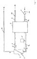
- the block diagram in Fig. 1 shows a feed pump 1 for introducing salt water 10 in a pressure compensating device 2 at a first pressure p1.
- the same salt water 11 which is, however, now subjected to a high working pressure p2, fed to the membrane module 3.
- the membrane 6 which is preferably configured as a so-called "crossflow" membrane, for example, 25% of the salt water 11, is desalted and discharged as desalinated water 12.
- the remaining part of the salt water 11, for example 75% can not pass through the membrane 6, but flows along the surface of the membrane 6 into the connecting line 5, via which it is discharged from the membrane module 3 as concentrated salt water 13.
- the concentrated salt water 13 which still has a high pressure, which is about the pressure p2, but is slightly lower, is then returned to the pressure compensation device 2. There, this high pressure p2 is exploited in an even closer manner to pressurize the salt water introduced into the pressure compensation device 2 and to supply the membrane module 3 to its inlet. At the same time, this pressure is used in the pressure compensation device to finally dissipate therein concentrated salt water 14 via the discharge line 4 and the pressure compensation device 2 supply unconcentrated salt water 10. All operations described are carried out simultaneously and continuously, so that the high working pressure nacharrinde high-pressure pump is not required and desalinated water 12 is continuously available.
- a memory 15 is provided according to the invention, which in such a case conducts additional water into the membrane module 3 and thus ensures that the high working pressure p2 is maintained and the flow across the membrane surface is not reduced.
- Fig. 2 shows a specific embodiment of a device according to the invention.
- This has two identical piston / cylinder devices 401, 402 with two cylinders arranged in alignment, each having an inlet chamber 201, 202 for receiving the salt water and each having an output chamber 101, 102 for receiving the concentrated salt water 13.
- Within the piston / cylinder devices 401, 402 is in each case a special piston 301, 302 arranged, which divides the piston interior in said chambers and in the image in the horizontal direction within the piston / cylinder device is movable.
- a supply line with a (passive) check valve 7 to the input chambers 201, 202.
- the check valves 7 are designed such that they open and allow a flow when the pressure in the supply line is greater than in the Input chambers 201, 202. Comparable check valves 8, but having a different flow direction can be found in the supply lines from the input chambers 201, 202 to the membrane module. 3
- the pistons 301, 302 are firmly connected to each other by means of a piston rod 30.
- Pinion 40, the z. B. can be driven by electric gear motors and engage in a mounted on the piston rod 30 teeth, the piston rod 30 and above the piston 301, 302 drive to compensate for pressure losses.
- the pistons are arranged so that they work in antiphase.
- the other piston connected via the piston rod 30 is in a position in which the volume of the input chamber 201 is minimal and the volume of the output chamber 101 is maximum (see. FIG. 2 ).
- the input chamber 202 is filled with water and the output chamber 101 is filled with concentrated salt water.
- the valves V1, V3, V4 and V6, shown here as switches, are controlled so that now V3 and V4 are closed while V1 and V6 are opened.
- Opening a valve in this context means making a flow connection to allow a flow to which the valve is opened purely mechanically.
- the closing of a valve means the interruption of a flow connection in order to prevent a flow, for which purely mechanically the valve is closed.
- the main valve V1 By opening the main valve V1 first escapes the pressure of the concentrated salt water in the output chamber 101. By opening the main valve V6, the output chamber 102 with pressure (for example, about 65 bar) is applied and the concentrated salt water flows into this chamber. At the same time, the salt water present in the inlet chamber 202 is pressed by the pressure-loaded piston to the membrane module 3.
- pressure for example, about 65 bar
- the introduction of the pressurized (for example, 65 bar) concentrate in the output chamber 102 through the piston rod 30 causes a movement of the other piston 301, thereby emptying the unpressurized output chamber 101.
- a negative pressure is created in the inlet chamber 201, which sucks in salt water and fills this chamber.
- concentrate concentrate 5 of the membrane module 3 are at least still the above about 65 bar pressure of concentrated salt water available.
- piston accumulator In order to maintain the flow of water along the membrane surface of the membrane 6 during the switching of the direction of movement of the pistons 301, 302, in particular at the moment of stoppage of the pistons 301, 302, according to the invention an additional piston / cylinder device 403, hereinafter referred to as piston accumulator , intended.
- This has three chambers, namely a feedwater chamber (input chamber) 203, which is connected to the supply line for the fed salt water 11, a concentrate chamber connected to the concentrate 5 (Output chamber) 103 and a pressure chamber 503.
- the pressure chamber 503 is connected on the one hand via an active valve V7 to the supply line 11 and on the other hand directly to a pressure accumulator 20, preferably a bladder accumulator.
- the valve V7 is always closed, it only serves to fill the existing from the pressure chamber 503 and the accumulator 20 circuit after an interruption again with the hydraulic fluid, such as a hydraulic fluid to fill and the required high pressure in the accumulator 20th restore.
- a pressure of approximately 70 bar acts on the piston 303 from the feed water chamber 203.
- the pressure in the reservoir 20 amounts to only 160 bar. Then acts from here because of the smaller piston area in the pressure chamber 503, a pressure of about 160/4, ie about 40 bar.
- the pressure in the concentrate circuit, ie the pressure of the discharged from the membrane module 3 concentrated salt water 13 is about 68 bar. This pressure acts on an area that covers three quarters of the piston surface. Consequently, a pressure of about 51 bar acts here.
- These two pressures act in the same direction and add up to a total of about 91 bar. Only about 70 bar in the feedwater chamber 203 counteract this resulting pressure. Thus, there is a sufficiently high pressure to press the piston 303, downwardly in the position shown, and thus to maintain the flow across the diaphragm 6.
- the piston accumulator 403 can be controlled so that only in the case of a pressure drop in the connecting line between the input chambers 201, 202 and the membrane module 3 or a reduction in the flow over the diaphragm 6, an additional pressure is exerted on said connecting line.
- suitable sensors can be provided which detect such a pressure drop or a flow reduction and trigger the corresponding pressure control.
- suitably controlled valves may be provided in the concentrate line 5 between the membrane module 3 and the piston / cylinder device 403, which are opened as needed to cause the described movement of the piston 303 downwardly by introducing a pressure into the concentrate chamber 103 , If such a pressure support is not needed, however, such a valve can also be closed again, so that due to the greater pressure in the feedwater chamber 203 relative to the pressure chamber 503 of the piston 303 is moved back up there and quasi remains in readiness attitude.
- ancillary or bypass valves may also be provided in parallel to the described main valves V1, V3, V4, V6 in order to reduce the load on the main valves and thus increase their service life.
- one or more flow restrictors may be provided to prevent abrupt pressure equalization by limiting the maximum flow rate and thus contributing to gradual pressure equalization and slow pressure changes rather than abrupt pressure fluctuations.
- the invention may also be applied to differently designed devices for the desalting of water by reverse osmosis, which, for example, instead of the two piston / cylinder devices shown a different number of such devices, e.g. having one or three piston / cylinder devices. These can basically be designed differently.
Landscapes
- Engineering & Computer Science (AREA)
- Chemical & Material Sciences (AREA)
- Water Supply & Treatment (AREA)
- Mechanical Engineering (AREA)
- General Engineering & Computer Science (AREA)
- Chemical Kinetics & Catalysis (AREA)
- Nanotechnology (AREA)
- Life Sciences & Earth Sciences (AREA)
- Hydrology & Water Resources (AREA)
- Environmental & Geological Engineering (AREA)
- Organic Chemistry (AREA)
- Electrochemistry (AREA)
- General Chemical & Material Sciences (AREA)
- Separation Using Semi-Permeable Membranes (AREA)
- Testing And Monitoring For Control Systems (AREA)
Priority Applications (2)
| Application Number | Priority Date | Filing Date | Title |
|---|---|---|---|
| SI200331167T SI1560637T1 (sl) | 2002-11-05 | 2003-07-21 | Postopek in naprava za razsoljevanje vode s pomočjo obratne osmoze |
| CY20081100578T CY1108111T1 (el) | 2002-11-05 | 2008-06-03 | Μια μεθοδος και μια διαταξη για την αφαλατωση νερου με γεφυρωση της πτωσης πιεσης |
Applications Claiming Priority (3)
| Application Number | Priority Date | Filing Date | Title |
|---|---|---|---|
| DE10251342 | 2002-11-05 | ||
| DE10251342A DE10251342B4 (de) | 2002-11-05 | 2002-11-05 | Verfahren und Vorrichtung zum Entsalzen von Wasser mit Druckabfallüberbrückung |
| PCT/EP2003/007916 WO2004041418A1 (de) | 2002-11-05 | 2003-07-21 | Verfahren und vorrichtung zum entsalzen von wasser mit druckabfallüberbrückung |
Publications (2)
| Publication Number | Publication Date |
|---|---|
| EP1560637A1 EP1560637A1 (de) | 2005-08-10 |
| EP1560637B1 true EP1560637B1 (de) | 2008-04-09 |
Family
ID=32115203
Family Applications (1)
| Application Number | Title | Priority Date | Filing Date |
|---|---|---|---|
| EP03810387A Expired - Lifetime EP1560637B1 (de) | 2002-11-05 | 2003-07-21 | Verfahren und vorrichtung zum entsalzen von wasser mit druckabfallüberbrückung |
Country Status (18)
| Country | Link |
|---|---|
| US (1) | US7550088B2 (pl) |
| EP (1) | EP1560637B1 (pl) |
| JP (1) | JP3926367B2 (pl) |
| KR (1) | KR100670760B1 (pl) |
| CN (1) | CN100409925C (pl) |
| AR (1) | AR041890A1 (pl) |
| AT (1) | ATE391549T1 (pl) |
| AU (1) | AU2003254549B2 (pl) |
| BR (1) | BR0315852B1 (pl) |
| CA (1) | CA2502736C (pl) |
| CY (1) | CY1108111T1 (pl) |
| DE (2) | DE10251342B4 (pl) |
| DK (1) | DK1560637T3 (pl) |
| ES (1) | ES2301883T3 (pl) |
| IL (1) | IL168159A (pl) |
| PL (1) | PL211959B1 (pl) |
| PT (1) | PT1560637E (pl) |
| WO (1) | WO2004041418A1 (pl) |
Families Citing this family (19)
| Publication number | Priority date | Publication date | Assignee | Title |
|---|---|---|---|---|
| DE102004061813A1 (de) | 2004-12-22 | 2006-07-06 | Robert Bosch Gmbh | Kolbenpumpe mit wenigstens einem Kolbenelement |
| WO2007134226A1 (en) * | 2006-05-12 | 2007-11-22 | Energy Recovery, Inc. | Hybrid ro/pro system |
| WO2010124170A2 (en) * | 2009-04-23 | 2010-10-28 | John Scialdone | Deep water desalination system and method |
| DE102009020932A1 (de) * | 2009-05-12 | 2010-11-18 | Fraunhofer-Gesellschaft zur Förderung der angewandten Forschung e.V. | Druckaustauscher mit Linearantrieb |
| JP2011056439A (ja) * | 2009-09-11 | 2011-03-24 | Toshiba Corp | 動力回収装置 |
| US20140042102A1 (en) * | 2012-08-07 | 2014-02-13 | World Wide Water Solutions | Front Flush Systems and Methods |
| CN106369015B (zh) * | 2016-09-07 | 2018-05-29 | 上海空间推进研究所 | 压差式能量回收泵 |
| IL251499B (en) * | 2017-04-02 | 2019-02-28 | Efraty Avi | Reverse osmosis installation in a closed circuit with a hydraulic arm for desalination with low energy consumption and a high recovery ratio |
| NL2019357B1 (en) * | 2017-07-27 | 2019-02-18 | Weir Minerals Netherlands Bv | Pump system for handling a slurry medium |
| GB201813792D0 (en) * | 2018-08-23 | 2018-10-10 | Davies Philip Andrew | Desalination system and method |
| US11072542B2 (en) | 2019-01-17 | 2021-07-27 | A. O. Smith Corporation | High water efficiency TDS creep solution |
| GB202017512D0 (en) | 2020-11-05 | 2020-12-23 | Univ Birmingham | Desalination system and method |
| US11502323B1 (en) | 2022-05-09 | 2022-11-15 | Rahul S Nana | Reverse electrodialysis cell and methods of use thereof |
| US11502322B1 (en) | 2022-05-09 | 2022-11-15 | Rahul S Nana | Reverse electrodialysis cell with heat pump |
| US12040517B2 (en) | 2022-11-15 | 2024-07-16 | Rahul S. Nana | Reverse electrodialysis or pressure-retarded osmosis cell and methods of use thereof |
| US11855324B1 (en) | 2022-11-15 | 2023-12-26 | Rahul S. Nana | Reverse electrodialysis or pressure-retarded osmosis cell with heat pump |
| JP2025538227A (ja) | 2022-11-15 | 2025-11-26 | エス ナナ,ラフル | 逆電気透析または圧力遅延浸透セルおよびその使用方法 |
| WO2025019455A2 (en) * | 2023-07-17 | 2025-01-23 | Purdue Research Foundation | Batch and semi-batch low salt rejection reverse osmosis desalination |
| CN118026409B (zh) * | 2024-04-11 | 2024-06-14 | 四川发展环境科学技术研究院有限公司 | 一种厌氧氨氧化耦合硫自养反硝化的废水脱氮系统 |
Family Cites Families (24)
| Publication number | Priority date | Publication date | Assignee | Title |
|---|---|---|---|---|
| US3498910A (en) * | 1968-09-03 | 1970-03-03 | Morris Mendelson | Apparatus and process for the controlled osmotic separation of water from sea water |
| FR1585376A (pl) * | 1968-10-11 | 1970-01-16 | ||
| IL51522A0 (en) * | 1976-02-27 | 1977-04-29 | Ocean Water Ltd | Improvements in or relating to water purification by reverse osmosis |
| US4178240A (en) * | 1976-05-17 | 1979-12-11 | Pinkerton Harry E | Fluid handling system |
| US4187173A (en) * | 1977-03-28 | 1980-02-05 | Keefer Bowie | Reverse osmosis method and apparatus |
| US4288326A (en) * | 1978-03-14 | 1981-09-08 | Keefer Bowie | Rotary shaft driven reverse osmosis method and apparatus |
| US4434056A (en) * | 1979-04-06 | 1984-02-28 | Keefer Bowie | Multi-cylinder reverse osmosis apparatus and method |
| US4367140A (en) * | 1979-11-05 | 1983-01-04 | Sykes Ocean Water Ltd. | Reverse osmosis liquid purification apparatus |
| US4637783A (en) | 1980-10-20 | 1987-01-20 | Sri International | Fluid motor-pumping apparatus and method for energy recovery |
| GR75052B (pl) * | 1981-01-05 | 1984-07-13 | Mesple Jose L R | |
| NL8304260A (nl) * | 1982-12-10 | 1984-07-02 | Uop Inc | Concentratie van alkoholische dranken. |
| HU197953B (en) * | 1984-07-30 | 1989-06-28 | Eszakdunantuli Regionalis Vizm | Method for utilizing the static gain of head of liquid medium |
| JPS6181584A (ja) | 1984-09-28 | 1986-04-25 | Shimadzu Corp | 送液ポンプ |
| JPH07102305B2 (ja) * | 1988-06-29 | 1995-11-08 | 株式会社ササクラ | 逆浸透膜濃縮装置 |
| DE3923722C2 (de) * | 1989-07-18 | 1997-07-10 | Uraca Pumpen | Kombination von Verdrängerpumpe, insbesondere Kolbenpumpe, und Verdrängermotor, insbesondere Kolbenmotor |
| US5531887A (en) * | 1995-05-24 | 1996-07-02 | Howell Laboratories, Inc. | Manually operated reverse osmosis desalinization system |
| US5628198A (en) * | 1996-05-13 | 1997-05-13 | Permar; Clark | Liquid treatment apparatus for filtering liquid under pressure |
| US6017200A (en) * | 1997-08-12 | 2000-01-25 | Science Applications International Corporation | Integrated pumping and/or energy recovery system |
| US6558537B1 (en) * | 1999-05-25 | 2003-05-06 | Miox Corporation | Portable hydration system |
| NO309398B1 (no) * | 1999-06-16 | 2001-01-22 | Bjoern Lyng | Fremgangsmåte og anlegg for produksjon av ferskvann fra saltholdig vann |
| DE19933147C2 (de) * | 1999-07-20 | 2002-04-18 | Aloys Wobben | Verfahren und Vorrichtung zum Entsalzen von Wasser |
| DE10066033B4 (de) * | 2000-11-21 | 2007-01-11 | Wobben, Aloys, Dipl.-Ing. | Verfahren und Vorrichtung zum Entsalzen von Wasser |
| CN2461915Y (zh) * | 2000-12-29 | 2001-11-28 | 刘博渊 | 带活塞式能量回收器的反渗透装置 |
| CN1156334C (zh) * | 2001-08-15 | 2004-07-07 | 天津大学 | 反渗透淡化系统阀控余压回收装置 |
-
2002
- 2002-11-05 DE DE10251342A patent/DE10251342B4/de not_active Expired - Fee Related
-
2003
- 2003-07-21 CA CA002502736A patent/CA2502736C/en not_active Expired - Fee Related
- 2003-07-21 ES ES03810387T patent/ES2301883T3/es not_active Expired - Lifetime
- 2003-07-21 WO PCT/EP2003/007916 patent/WO2004041418A1/de not_active Ceased
- 2003-07-21 PL PL375761A patent/PL211959B1/pl unknown
- 2003-07-21 AT AT03810387T patent/ATE391549T1/de active
- 2003-07-21 CN CNB038248344A patent/CN100409925C/zh not_active Expired - Fee Related
- 2003-07-21 DE DE50309593T patent/DE50309593D1/de not_active Expired - Lifetime
- 2003-07-21 BR BRPI0315852-7A patent/BR0315852B1/pt not_active IP Right Cessation
- 2003-07-21 US US10/533,851 patent/US7550088B2/en not_active Expired - Fee Related
- 2003-07-21 DK DK03810387T patent/DK1560637T3/da active
- 2003-07-21 AU AU2003254549A patent/AU2003254549B2/en not_active Ceased
- 2003-07-21 EP EP03810387A patent/EP1560637B1/de not_active Expired - Lifetime
- 2003-07-21 KR KR1020057007943A patent/KR100670760B1/ko not_active Expired - Fee Related
- 2003-07-21 PT PT03810387T patent/PT1560637E/pt unknown
- 2003-07-21 JP JP2004548709A patent/JP3926367B2/ja not_active Expired - Fee Related
- 2003-11-05 AR ARP030104046A patent/AR041890A1/es not_active Application Discontinuation
-
2005
- 2005-04-20 IL IL168159A patent/IL168159A/en unknown
-
2008
- 2008-06-03 CY CY20081100578T patent/CY1108111T1/el unknown
Also Published As
| Publication number | Publication date |
|---|---|
| DE10251342B4 (de) | 2013-03-14 |
| AU2003254549B2 (en) | 2005-12-15 |
| CA2502736C (en) | 2008-07-15 |
| CY1108111T1 (el) | 2014-02-12 |
| WO2004041418A1 (de) | 2004-05-21 |
| PL375761A1 (pl) | 2005-12-12 |
| KR20050084667A (ko) | 2005-08-26 |
| CA2502736A1 (en) | 2004-05-21 |
| BR0315852A (pt) | 2005-09-20 |
| DE10251342A1 (de) | 2004-05-19 |
| PT1560637E (pt) | 2008-05-29 |
| EP1560637A1 (de) | 2005-08-10 |
| AR041890A1 (es) | 2005-06-01 |
| DE50309593D1 (de) | 2008-05-21 |
| AU2003254549A1 (en) | 2004-06-07 |
| PL211959B1 (pl) | 2012-07-31 |
| KR100670760B1 (ko) | 2007-01-17 |
| CN1852758A (zh) | 2006-10-25 |
| JP2006504521A (ja) | 2006-02-09 |
| DK1560637T3 (da) | 2008-05-19 |
| US20060124546A1 (en) | 2006-06-15 |
| CN100409925C (zh) | 2008-08-13 |
| BR0315852B1 (pt) | 2012-06-26 |
| ATE391549T1 (de) | 2008-04-15 |
| ES2301883T3 (es) | 2008-07-01 |
| US7550088B2 (en) | 2009-06-23 |
| IL168159A (en) | 2009-07-20 |
| JP3926367B2 (ja) | 2007-06-06 |
Similar Documents
| Publication | Publication Date | Title |
|---|---|---|
| EP1560637B1 (de) | Verfahren und vorrichtung zum entsalzen von wasser mit druckabfallüberbrückung | |
| DE19933147C2 (de) | Verfahren und Vorrichtung zum Entsalzen von Wasser | |
| DE10066033B4 (de) | Verfahren und Vorrichtung zum Entsalzen von Wasser | |
| EP2855945B2 (de) | Verfahren zum betrieb eines hydrauliksystems | |
| DE3141033A1 (de) | Fluessigkeitsfoerdersystem mit energierueckgewinnungseinrichtung | |
| DE102009053618A1 (de) | Hydraulikantrieb mit Energierückgewinnung | |
| WO2006089688A1 (de) | Hydraulikantrieb, insbesondere für zweizylinder-dickstoffpumpen | |
| DE19962124A1 (de) | Hydraulisches Zweikreis-Lenksystem | |
| DE102006015675A1 (de) | Kleinmengen-Umkehrosmose-Anlage mit Doppelmembran-Permeatpumpe | |
| DE102020125547B4 (de) | Prozess-Wasseranalyse-Probennahmeanordnung | |
| EP2062719B1 (de) | Siebwechsler | |
| DE4213714C1 (pl) | ||
| DE10302580A1 (de) | Wasser-Reinigungsvorrichtung | |
| EP0029223B1 (de) | Hydraulisches Versorgungssystem einer Pulsationspresse | |
| DE10057613C2 (de) | Verfahren und Vorrichtung zum Entsalzen von Wasser | |
| EP0874682B1 (de) | Verfahren zum entsalzen von wasser und vorrichtung zur durchführung des verfahrens | |
| WO1998048174A1 (de) | Antrieb für einen hydraulischen differentialzylinder | |
| WO2007057012A1 (de) | Flüssigkeitsbehandlungsanordnung, insbondere wasserbehandlungsanordnung | |
| WO2002064510A1 (de) | Vorrichtung zum entsalzen von wasser mit der umkehrosmose | |
| DE102021004616A1 (de) | Filtervorrichtung | |
| DE102006060335B3 (de) | Hydraulische Ventilanordnung | |
| DE202022104124U1 (de) | Wasseranlage zur Reinigung einer Betonpumpe | |
| DE2845922A1 (de) | Vorgesteuertes wegeventil mit verteilerfunktion | |
| DE2951578C2 (de) | Steuerung für hydraulische Zylinder-Kolben-Aggregate von Schreitausbaugestellen | |
| DE2818989A1 (de) | Filterpresse |
Legal Events
| Date | Code | Title | Description |
|---|---|---|---|
| PUAI | Public reference made under article 153(3) epc to a published international application that has entered the european phase |
Free format text: ORIGINAL CODE: 0009012 |
|
| 17P | Request for examination filed |
Effective date: 20050606 |
|
| AK | Designated contracting states |
Kind code of ref document: A1 Designated state(s): AT BE BG CH CY CZ DE DK EE ES FI FR GB GR HU IE IT LI LU MC NL PT RO SE SI SK TR |
|
| AX | Request for extension of the european patent |
Extension state: AL LT LV MK |
|
| DAX | Request for extension of the european patent (deleted) | ||
| GRAP | Despatch of communication of intention to grant a patent |
Free format text: ORIGINAL CODE: EPIDOSNIGR1 |
|
| GRAS | Grant fee paid |
Free format text: ORIGINAL CODE: EPIDOSNIGR3 |
|
| GRAA | (expected) grant |
Free format text: ORIGINAL CODE: 0009210 |
|
| AK | Designated contracting states |
Kind code of ref document: B1 Designated state(s): AT BE BG CH CY CZ DE DK EE ES FI FR GB GR HU IE IT LI LU MC NL PT RO SE SI SK TR |
|
| REG | Reference to a national code |
Ref country code: GB Ref legal event code: FG4D Free format text: NOT ENGLISH |
|
| REG | Reference to a national code |
Ref country code: CH Ref legal event code: EP |
|
| REG | Reference to a national code |
Ref country code: IE Ref legal event code: FG4D Free format text: LANGUAGE OF EP DOCUMENT: GERMAN |
|
| REG | Reference to a national code |
Ref country code: DK Ref legal event code: T3 Ref country code: RO Ref legal event code: EPE |
|
| REF | Corresponds to: |
Ref document number: 50309593 Country of ref document: DE Date of ref document: 20080521 Kind code of ref document: P |
|
| REG | Reference to a national code |
Ref country code: PT Ref legal event code: SC4A Free format text: AVAILABILITY OF NATIONAL TRANSLATION Effective date: 20080516 |
|
| REG | Reference to a national code |
Ref country code: ES Ref legal event code: FG2A Ref document number: 2301883 Country of ref document: ES Kind code of ref document: T3 |
|
| REG | Reference to a national code |
Ref country code: GR Ref legal event code: EP Ref document number: 20080401536 Country of ref document: GR |
|
| REG | Reference to a national code |
Ref country code: SE Ref legal event code: TRGR |
|
| REG | Reference to a national code |
Ref country code: CH Ref legal event code: NV Representative=s name: ZIMMERLI, WAGNER & PARTNER AG |
|
| PG25 | Lapsed in a contracting state [announced via postgrant information from national office to epo] |
Ref country code: FI Free format text: LAPSE BECAUSE OF FAILURE TO SUBMIT A TRANSLATION OF THE DESCRIPTION OR TO PAY THE FEE WITHIN THE PRESCRIBED TIME-LIMIT Effective date: 20080409 |
|
| ET | Fr: translation filed | ||
| PLBE | No opposition filed within time limit |
Free format text: ORIGINAL CODE: 0009261 |
|
| STAA | Information on the status of an ep patent application or granted ep patent |
Free format text: STATUS: NO OPPOSITION FILED WITHIN TIME LIMIT |
|
| 26N | No opposition filed |
Effective date: 20090112 |
|
| PG25 | Lapsed in a contracting state [announced via postgrant information from national office to epo] |
Ref country code: MC Free format text: LAPSE BECAUSE OF NON-PAYMENT OF DUE FEES Effective date: 20080731 |
|
| REG | Reference to a national code |
Ref country code: HU Ref legal event code: AG4A Ref document number: E005387 Country of ref document: HU |
|
| REG | Reference to a national code |
Ref country code: CH Ref legal event code: PFA Owner name: WOBBEN, ALOYS Free format text: WOBBEN, ALOYS#ARGESTRASSE 19#26607 AURICH (DE) -TRANSFER TO- WOBBEN, ALOYS#ARGESTRASSE 19#26607 AURICH (DE) |
|
| PG25 | Lapsed in a contracting state [announced via postgrant information from national office to epo] |
Ref country code: LU Free format text: LAPSE BECAUSE OF NON-PAYMENT OF DUE FEES Effective date: 20080721 |
|
| REG | Reference to a national code |
Ref country code: CH Ref legal event code: NV Representative=s name: WAGNER PATENT AG, CH |
|
| REG | Reference to a national code |
Ref country code: FR Ref legal event code: PLFP Year of fee payment: 14 |
|
| REG | Reference to a national code |
Ref country code: FR Ref legal event code: PLFP Year of fee payment: 15 |
|
| REG | Reference to a national code |
Ref country code: FR Ref legal event code: PLFP Year of fee payment: 16 |
|
| PGFP | Annual fee paid to national office [announced via postgrant information from national office to epo] |
Ref country code: IT Payment date: 20180720 Year of fee payment: 16 Ref country code: IE Payment date: 20180720 Year of fee payment: 16 Ref country code: NL Payment date: 20180723 Year of fee payment: 16 Ref country code: FR Payment date: 20180723 Year of fee payment: 16 Ref country code: EE Payment date: 20180720 Year of fee payment: 16 Ref country code: DE Payment date: 20180802 Year of fee payment: 16 Ref country code: ES Payment date: 20180829 Year of fee payment: 16 Ref country code: RO Payment date: 20180709 Year of fee payment: 16 |
|
| PGFP | Annual fee paid to national office [announced via postgrant information from national office to epo] |
Ref country code: AT Payment date: 20180719 Year of fee payment: 16 Ref country code: HU Payment date: 20180705 Year of fee payment: 16 Ref country code: BE Payment date: 20180723 Year of fee payment: 16 Ref country code: SI Payment date: 20180705 Year of fee payment: 16 Ref country code: SK Payment date: 20180711 Year of fee payment: 16 Ref country code: BG Payment date: 20180723 Year of fee payment: 16 Ref country code: TR Payment date: 20180706 Year of fee payment: 16 Ref country code: DK Payment date: 20180725 Year of fee payment: 16 Ref country code: CH Payment date: 20180725 Year of fee payment: 16 Ref country code: GR Payment date: 20180724 Year of fee payment: 16 Ref country code: CZ Payment date: 20180711 Year of fee payment: 16 Ref country code: SE Payment date: 20180725 Year of fee payment: 16 Ref country code: GB Payment date: 20180725 Year of fee payment: 16 |
|
| PGFP | Annual fee paid to national office [announced via postgrant information from national office to epo] |
Ref country code: PT Payment date: 20180705 Year of fee payment: 16 |
|
| PGFP | Annual fee paid to national office [announced via postgrant information from national office to epo] |
Ref country code: CY Payment date: 20180717 Year of fee payment: 16 |
|
| REG | Reference to a national code |
Ref country code: DE Ref legal event code: R119 Ref document number: 50309593 Country of ref document: DE |
|
| REG | Reference to a national code |
Ref country code: EE Ref legal event code: MM4A Ref document number: E002106 Country of ref document: EE Effective date: 20190731 |
|
| REG | Reference to a national code |
Ref country code: DK Ref legal event code: EBP Effective date: 20190731 |
|
| REG | Reference to a national code |
Ref country code: CH Ref legal event code: PL |
|
| REG | Reference to a national code |
Ref country code: SE Ref legal event code: EUG |
|
| REG | Reference to a national code |
Ref country code: AT Ref legal event code: MM01 Ref document number: 391549 Country of ref document: AT Kind code of ref document: T Effective date: 20190721 |
|
| GBPC | Gb: european patent ceased through non-payment of renewal fee |
Effective date: 20190721 |
|
| REG | Reference to a national code |
Ref country code: SK Ref legal event code: MM4A Ref document number: E 3372 Country of ref document: SK Effective date: 20190721 |
|
| REG | Reference to a national code |
Ref country code: BE Ref legal event code: MM Effective date: 20190731 |
|
| REG | Reference to a national code |
Ref country code: SI Ref legal event code: KO00 Effective date: 20200311 |
|
| PG25 | Lapsed in a contracting state [announced via postgrant information from national office to epo] |
Ref country code: EE Free format text: LAPSE BECAUSE OF NON-PAYMENT OF DUE FEES Effective date: 20190731 Ref country code: AT Free format text: LAPSE BECAUSE OF NON-PAYMENT OF DUE FEES Effective date: 20190721 Ref country code: GB Free format text: LAPSE BECAUSE OF NON-PAYMENT OF DUE FEES Effective date: 20190721 Ref country code: RO Free format text: LAPSE BECAUSE OF NON-PAYMENT OF DUE FEES Effective date: 20190721 Ref country code: HU Free format text: LAPSE BECAUSE OF NON-PAYMENT OF DUE FEES Effective date: 20190722 Ref country code: BG Free format text: LAPSE BECAUSE OF NON-PAYMENT OF DUE FEES Effective date: 20200131 Ref country code: GR Free format text: LAPSE BECAUSE OF NON-PAYMENT OF DUE FEES Effective date: 20200206 Ref country code: SE Free format text: LAPSE BECAUSE OF NON-PAYMENT OF DUE FEES Effective date: 20190722 Ref country code: DE Free format text: LAPSE BECAUSE OF NON-PAYMENT OF DUE FEES Effective date: 20200201 Ref country code: NL Free format text: LAPSE BECAUSE OF NON-PAYMENT OF DUE FEES Effective date: 20190801 Ref country code: PT Free format text: LAPSE BECAUSE OF NON-PAYMENT OF DUE FEES Effective date: 20200121 |
|
| REG | Reference to a national code |
Ref country code: NL Ref legal event code: MM Effective date: 20190801 |
|
| PG25 | Lapsed in a contracting state [announced via postgrant information from national office to epo] |
Ref country code: LI Free format text: LAPSE BECAUSE OF NON-PAYMENT OF DUE FEES Effective date: 20190731 Ref country code: CY Free format text: LAPSE BECAUSE OF NON-PAYMENT OF DUE FEES Effective date: 20190721 Ref country code: CZ Free format text: LAPSE BECAUSE OF NON-PAYMENT OF DUE FEES Effective date: 20190721 Ref country code: SI Free format text: LAPSE BECAUSE OF NON-PAYMENT OF DUE FEES Effective date: 20190722 Ref country code: BE Free format text: LAPSE BECAUSE OF NON-PAYMENT OF DUE FEES Effective date: 20190731 Ref country code: SK Free format text: LAPSE BECAUSE OF NON-PAYMENT OF DUE FEES Effective date: 20190721 Ref country code: CH Free format text: LAPSE BECAUSE OF NON-PAYMENT OF DUE FEES Effective date: 20190731 |
|
| PG25 | Lapsed in a contracting state [announced via postgrant information from national office to epo] |
Ref country code: FR Free format text: LAPSE BECAUSE OF NON-PAYMENT OF DUE FEES Effective date: 20190731 |
|
| PG25 | Lapsed in a contracting state [announced via postgrant information from national office to epo] |
Ref country code: DK Free format text: LAPSE BECAUSE OF NON-PAYMENT OF DUE FEES Effective date: 20190731 Ref country code: IE Free format text: LAPSE BECAUSE OF NON-PAYMENT OF DUE FEES Effective date: 20190721 |
|
| PG25 | Lapsed in a contracting state [announced via postgrant information from national office to epo] |
Ref country code: IT Free format text: LAPSE BECAUSE OF NON-PAYMENT OF DUE FEES Effective date: 20190721 |
|
| REG | Reference to a national code |
Ref country code: ES Ref legal event code: FD2A Effective date: 20201130 |
|
| PG25 | Lapsed in a contracting state [announced via postgrant information from national office to epo] |
Ref country code: ES Free format text: LAPSE BECAUSE OF NON-PAYMENT OF DUE FEES Effective date: 20190722 |
|
| PG25 | Lapsed in a contracting state [announced via postgrant information from national office to epo] |
Ref country code: TR Free format text: LAPSE BECAUSE OF NON-PAYMENT OF DUE FEES Effective date: 20190721 |