EP1560544B1 - Geflochtener stent und verfahren zu dessen herstellung - Google Patents
Geflochtener stent und verfahren zu dessen herstellung Download PDFInfo
- Publication number
- EP1560544B1 EP1560544B1 EP03779154A EP03779154A EP1560544B1 EP 1560544 B1 EP1560544 B1 EP 1560544B1 EP 03779154 A EP03779154 A EP 03779154A EP 03779154 A EP03779154 A EP 03779154A EP 1560544 B1 EP1560544 B1 EP 1560544B1
- Authority
- EP
- European Patent Office
- Prior art keywords
- stent
- filaments
- braiding
- region
- mandrel
- Prior art date
- Legal status (The legal status is an assumption and is not a legal conclusion. Google has not performed a legal analysis and makes no representation as to the accuracy of the status listed.)
- Expired - Lifetime
Links
Images


Classifications
-
- A—HUMAN NECESSITIES
- A61—MEDICAL OR VETERINARY SCIENCE; HYGIENE
- A61F—FILTERS IMPLANTABLE INTO BLOOD VESSELS; PROSTHESES; DEVICES PROVIDING PATENCY TO, OR PREVENTING COLLAPSING OF, TUBULAR STRUCTURES OF THE BODY, e.g. STENTS; ORTHOPAEDIC, NURSING OR CONTRACEPTIVE DEVICES; FOMENTATION; TREATMENT OR PROTECTION OF EYES OR EARS; BANDAGES, DRESSINGS OR ABSORBENT PADS; FIRST-AID KITS
- A61F2/00—Filters implantable into blood vessels; Prostheses, i.e. artificial substitutes or replacements for parts of the body; Appliances for connecting them with the body; Devices providing patency to, or preventing collapsing of, tubular structures of the body, e.g. stents
- A61F2/82—Devices providing patency to, or preventing collapsing of, tubular structures of the body, e.g. stents
- A61F2/86—Stents in a form characterised by the wire-like elements; Stents in the form characterised by a net-like or mesh-like structure
- A61F2/90—Stents in a form characterised by the wire-like elements; Stents in the form characterised by a net-like or mesh-like structure characterised by a net-like or mesh-like structure
-
- D—TEXTILES; PAPER
- D04—BRAIDING; LACE-MAKING; KNITTING; TRIMMINGS; NON-WOVEN FABRICS
- D04C—BRAIDING OR MANUFACTURE OF LACE, INCLUDING BOBBIN-NET OR CARBONISED LACE; BRAIDING MACHINES; BRAID; LACE
- D04C1/00—Braid or lace, e.g. pillow-lace; Processes for the manufacture thereof
- D04C1/06—Braid or lace serving particular purposes
-
- D—TEXTILES; PAPER
- D04—BRAIDING; LACE-MAKING; KNITTING; TRIMMINGS; NON-WOVEN FABRICS
- D04C—BRAIDING OR MANUFACTURE OF LACE, INCLUDING BOBBIN-NET OR CARBONISED LACE; BRAIDING MACHINES; BRAID; LACE
- D04C3/00—Braiding or lacing machines
- D04C3/48—Auxiliary devices
-
- A—HUMAN NECESSITIES
- A61—MEDICAL OR VETERINARY SCIENCE; HYGIENE
- A61F—FILTERS IMPLANTABLE INTO BLOOD VESSELS; PROSTHESES; DEVICES PROVIDING PATENCY TO, OR PREVENTING COLLAPSING OF, TUBULAR STRUCTURES OF THE BODY, e.g. STENTS; ORTHOPAEDIC, NURSING OR CONTRACEPTIVE DEVICES; FOMENTATION; TREATMENT OR PROTECTION OF EYES OR EARS; BANDAGES, DRESSINGS OR ABSORBENT PADS; FIRST-AID KITS
- A61F2230/00—Geometry of prostheses classified in groups A61F2/00 - A61F2/26 or A61F2/82 or A61F9/00 or A61F11/00 or subgroups thereof
- A61F2230/0002—Two-dimensional shapes, e.g. cross-sections
- A61F2230/0028—Shapes in the form of latin or greek characters
- A61F2230/0054—V-shaped
-
- A—HUMAN NECESSITIES
- A61—MEDICAL OR VETERINARY SCIENCE; HYGIENE
- A61F—FILTERS IMPLANTABLE INTO BLOOD VESSELS; PROSTHESES; DEVICES PROVIDING PATENCY TO, OR PREVENTING COLLAPSING OF, TUBULAR STRUCTURES OF THE BODY, e.g. STENTS; ORTHOPAEDIC, NURSING OR CONTRACEPTIVE DEVICES; FOMENTATION; TREATMENT OR PROTECTION OF EYES OR EARS; BANDAGES, DRESSINGS OR ABSORBENT PADS; FIRST-AID KITS
- A61F2230/00—Geometry of prostheses classified in groups A61F2/00 - A61F2/26 or A61F2/82 or A61F9/00 or A61F11/00 or subgroups thereof
- A61F2230/0063—Three-dimensional shapes
- A61F2230/0067—Three-dimensional shapes conical
-
- A—HUMAN NECESSITIES
- A61—MEDICAL OR VETERINARY SCIENCE; HYGIENE
- A61F—FILTERS IMPLANTABLE INTO BLOOD VESSELS; PROSTHESES; DEVICES PROVIDING PATENCY TO, OR PREVENTING COLLAPSING OF, TUBULAR STRUCTURES OF THE BODY, e.g. STENTS; ORTHOPAEDIC, NURSING OR CONTRACEPTIVE DEVICES; FOMENTATION; TREATMENT OR PROTECTION OF EYES OR EARS; BANDAGES, DRESSINGS OR ABSORBENT PADS; FIRST-AID KITS
- A61F2250/00—Special features of prostheses classified in groups A61F2/00 - A61F2/26 or A61F2/82 or A61F9/00 or A61F11/00 or subgroups thereof
- A61F2250/0014—Special features of prostheses classified in groups A61F2/00 - A61F2/26 or A61F2/82 or A61F9/00 or A61F11/00 or subgroups thereof having different values of a given property or geometrical feature, e.g. mechanical property or material property, at different locations within the same prosthesis
- A61F2250/0018—Special features of prostheses classified in groups A61F2/00 - A61F2/26 or A61F2/82 or A61F9/00 or A61F11/00 or subgroups thereof having different values of a given property or geometrical feature, e.g. mechanical property or material property, at different locations within the same prosthesis differing in elasticity, stiffness or compressibility
-
- A—HUMAN NECESSITIES
- A61—MEDICAL OR VETERINARY SCIENCE; HYGIENE
- A61F—FILTERS IMPLANTABLE INTO BLOOD VESSELS; PROSTHESES; DEVICES PROVIDING PATENCY TO, OR PREVENTING COLLAPSING OF, TUBULAR STRUCTURES OF THE BODY, e.g. STENTS; ORTHOPAEDIC, NURSING OR CONTRACEPTIVE DEVICES; FOMENTATION; TREATMENT OR PROTECTION OF EYES OR EARS; BANDAGES, DRESSINGS OR ABSORBENT PADS; FIRST-AID KITS
- A61F2250/00—Special features of prostheses classified in groups A61F2/00 - A61F2/26 or A61F2/82 or A61F9/00 or A61F11/00 or subgroups thereof
- A61F2250/0014—Special features of prostheses classified in groups A61F2/00 - A61F2/26 or A61F2/82 or A61F9/00 or A61F11/00 or subgroups thereof having different values of a given property or geometrical feature, e.g. mechanical property or material property, at different locations within the same prosthesis
- A61F2250/0039—Special features of prostheses classified in groups A61F2/00 - A61F2/26 or A61F2/82 or A61F9/00 or A61F11/00 or subgroups thereof having different values of a given property or geometrical feature, e.g. mechanical property or material property, at different locations within the same prosthesis differing in diameter
-
- D—TEXTILES; PAPER
- D10—INDEXING SCHEME ASSOCIATED WITH SUBLASSES OF SECTION D, RELATING TO TEXTILES
- D10B—INDEXING SCHEME ASSOCIATED WITH SUBLASSES OF SECTION D, RELATING TO TEXTILES
- D10B2403/00—Details of fabric structure established in the fabric forming process
- D10B2403/03—Shape features
- D10B2403/033—Three dimensional fabric, e.g. forming or comprising cavities in or protrusions from the basic planar configuration, or deviations from the cylindrical shape as generally imposed by the fabric forming process
- D10B2403/0333—Three dimensional fabric, e.g. forming or comprising cavities in or protrusions from the basic planar configuration, or deviations from the cylindrical shape as generally imposed by the fabric forming process with tubular portions of variable diameter or distinct axial orientation
-
- D—TEXTILES; PAPER
- D10—INDEXING SCHEME ASSOCIATED WITH SUBLASSES OF SECTION D, RELATING TO TEXTILES
- D10B—INDEXING SCHEME ASSOCIATED WITH SUBLASSES OF SECTION D, RELATING TO TEXTILES
- D10B2509/00—Medical; Hygiene
- D10B2509/06—Vascular grafts; stents
Definitions
- This invention relates generally to stents and stent-grafts, and more specifically, to braided stents and stent-grafts having segments of different strength and rigidity along the length, and/or different diameters of varying or constant strength and rigidity along the length.
- a stent is an elongated device used to support a luminal wall.
- a stent, along with a graft cover or liner, together provide an unobstructed conduit for fluid flow in the area of a stenosis.
- Such a stent-graft would typically have a tubular graft layer covering, or lining, the inside or outside of the stent (or both), thus providing a fluid conduit to bypass a stenosis or otherwise diseased body passageway.
- stent architectures are known in the art, including many designs comprising a filament or number of filaments, such as a wire or wires, wound or braided into a particular configuration. Included among these wire stent configurations are braided stents, such as is described in U.S. Patent No. 4,655,771 to Hans I. Wallsten .
- the Wallsten patent is only one example of the many variations of braided stents known in the art and thus is not intended to be a limitation of the invention described herein later.
- Braided stents tend to be very flexible, having the ' ability to be placed in tortuous anatomy and still maintain patency. The flexibility of braided stents make them particularly well-suited for use in Intraluminal delivery where the lumen of the vessel becomes contorted and irregular both before and after placement of the stent.
- stents and stent-grafts having a first small diameter compressed configuration may be introduced into a body lumen at a point remote from a site in that lumen in need of repair and then transported through that lumen, typically through a catheter, to that site. Once the site In need of repair is reached, the stent or stent-graft is either expanded or allowed to expand to a second, expanded configuration to provide an open passageway through that site.
- WO 03/057079 A1 that forms part of the art under Article 54(3) EPC describes a body insertable tubular stent 16 comprising discrete tubular segments in an alternating sequence of segments having high axial stiffness 22 and segments having low axial stiffness 24.
- the stent 16 can be formed either by simply winding and interbraiding multiple elastic biocompatible strands 28, thereby altering a pitch at least once during winding to form sections with different axial stiffness, or by placing the wound strand 28 onto a heat-set mandrel 34 having a plurality of mandrel segments 38, 40 with different diameters.
- a predetermined diameter i.e.
- the diameter of the deployed stent 16 is constant. This can best bee seen by comparing Figures 5 and 6, where the same stent 34 is shown in a shape prior to implantation ( Figure 5) showing sections of different diameter and in the implanted situation ( Figure 6), where the diameter of stent 34 is the same over its entire length.
- a stent as defined in the preamble of claim 1 is disclosed in EPO897 698 A2 .
- the stent of this document has different mesh patterns
- the stent generally has a tubular shape and functions to support a part of a body lumen from inside thereof. When being delivered the stent may have the form of a football, thus avoiding harming the wall of the lumen it has to be transported through and deployed in. Once deployed, the stent will have the same diameter throughout the entire length.
- the present invention provides a stent having segments of different diameters of varying or constant properties along its length.
- the diameter along the length of the stent is constant, but the rigidity of the stent changes along the longitudinal axis.
- the rigidity of the stent stays the same along the longitudinal length, but the diameter changes.
- both rigidity and diameter change along the length of the stent. This variance in diameter and radial strength or rigidity is achieved through the use of different numbers of filaments braided into the stent at different locations. Generally, where more rigidity, or the same rigidity with a larger diameter, is desired, more filaments are added.
- the invention comprises a stent having a narrow region and a broader region with the broader region comprising more filaments than the narrow region such that increased radial strength is exhibited in the broader region.
- the stent of the present invention has a first plurality of filaments extending throughout the narrow region and the broader region, and a second plurality of filaments extending along only the broader region. The second plurality of filaments is braided into the first plurality of filaments.
- the stent further comprises a transition region between the narrow region and the broader region. The transition region is comprised of the first plurality of filaments whose braiding increases in diameter from the narrow region to the broader region.
- Also included in the invention is a method of braiding a stent having a region of relatively greater flexibility and a region of relatively higher radial strength.
- the method includes the steps of first braiding a first plurality of filaments to form the more flexible region, and then adding a second plurality of filaments to the first plurality and together braiding the combination to form the more rigid region of the stent.
- the method preferably includes the steps of first braiding a first plurality of filaments to form a narrow region, then combining a second plurality of filaments to the first portion, and braiding the second plurality of filaments with the first plurality of filaments to form a broader region from the combination of the first and second plurality of filaments.
- the method preferably includes braiding the stent around a mandrel having a mandrel body comprised of a first portion and a second portion, wherein the first step comprises braiding the first plurality of filaments about the first mandrel portion, and the last step comprises braiding the second plurality of filaments combined with the first plurality of filaments about the second mandrel portion.
- the second plurality of filaments are present only in the more rigid region.
- the second mandrel portion preferably has a larger diameter than the first mandrel portion.
- An optional, but preferred feature of the invention is the provision of atraumatic termination to the braided stent structure, both at the stent ends and at the mid-stent locations where one plurality of braided filaments ends.
- a braided stent is one formed by at least two sets of parallel continuous filaments, the two sets traversing the circumference of the stent in lengthwise but angularly intersecting directions.
- the two sets of filaments are interlaced or Interwoven to form a supportive structure.
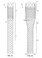
- the stent shown in Fig. 1A comprises a relatively flexible region 11 and a relatively rigid region 12 (having greater radial strength than flexible region 11).
- Rigid region 12 comprises more filaments than flexible region 11 and therefore exhibits greater radial strength.
- the number of filaments in rigid region 12 is twice that of flexible region 11.
- a stent as shown In Fig. 1A can be braided on a mandrel (not shown) using the method described in detail below.
- the stent comprises a narrow (or smaller diameter) region 110 defining a first lumen comprised of a first plurality of filaments, and a broader (or larger diameter) region 120 defining a larger lumen than said first lumen.
- Broader region 120 is comprised of the plurality of filaments from narrow region 110, plus a second plurality of filaments braided into the first plurality of filaments.
- Narrow region 110 has greater flexibility than broader region 120, and, likewise, broader region 120 exhibits greater radial strength than narrow region 110.
- Fig. 1B also shows transition region 130.
- Transition region is formed between narrow region 110 and broader region 120 and is comprised of the filaments which make up narrow region 110.
- Transition region 130 is formed during braiding on a mandrel of changing diameter, as described in more detail below.
- the stents shown in Figs. 1A and 1B are unitary stents. That is, the stent is one piece, unlike modular stent designs in which two or more stent segments are assembled together to form the various parts of the overall device (e.g., a trunk section and two legs).
- a unitary stent contemplates a stent whose entire length is made as a single unit, without the need to attach additional stent segments upon deployment.
- the stent as shown In Fig. 1B for example, although unitary, exhibits different radial strengths along its longitudinal axis. This Is because of the introduction of additional filaments in broader region 120.
- unitary stent 100 as shown in Fig. 1B is merely an exemplary embodiment, and that this invention is applicable to "modular" braided stents as well.
- module means a stent having at least two discrete portions adapted for assembly in situ.
- one type of exemplary modular stent may Include a modular bifurcated stent comprising a trunk section with a bifurcated region that terminates in two short sockets into which two discrete leg members are adapted to be inserted.
- such general configurations are well-known in the art.
- Braiding of the filaments which form the stent of the present invention may be performed on a braiding machine having a predetermined plurality of bobbin carriers adapted to revolve in a pattern about a longitudinal axis.
- a first set of bobbin carriers may be adapted to revolve in a first circumferential direction and a second set of bobbin carriers may be adapted to revolve in a second circumferential direction, each bobbin carrier adapted to carry at least one bobbin.
- Each bobbin is adapted to provide one or more filaments for braiding the stent.
- braiding of the narrow, or flexible, region comprises using filaments from a first portion of the predetermined plurality of bobbins to braid the narrow portion about the first, narrow portion of the detachable mandrel leg positioned substantially along the longitudinal axis in a braiding zone.
- the braiding zone is defined as a conical zone defined by the filaments extending from the bobbins to the stent on the mandrel.
- the preferred number of filaments used to braid the narrow region is 12, although any suitable number may be used to achieve the desired balance between compressibility and radial strength of this region.
- the filaments used with the present invention may be any known to those skilled in the art, and preferably may be wire, such as nitinol or stainless steel, or may comprise a polymer.
- the process comprises adding filaments from a second portion of the predetermined plurality of bobbins to increase the number of filaments used to braid the broader region about the second portion of the detachable mandrel leg positioned in the braiding zone.
- the additional filaments added are used in conjunction with the filaments already in place from braiding the narrow region of the stent.
- this second step comprises using filaments from both portions of the predetermined plurality of bobbins to braid the body about the second, larger diameter, mandrel body positioned in the braiding zone.
- the second plurality of filaments are only used in the broader region, and nowhere else in the stent.
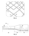
- Fig. 2 shows a flattened, partial view of the lower part of broader region 120 shown in Fig. 1.
- This part of the stent according to the present invention is discussed in more detail below.
- one filament is positioned radially outward relative to the other filament.
- that filament may, for example be in the radial inward position in one overlap and in the radial outward position in a next overlap, or may in the inward position for two overlaps and in the outward position for the next two, and so on.
- exemplary braided stents are disclosed In U.S. Patent No. 4,655,771 to Hans I. Wallsten .
- a typical braided stent is formed on a mandrel by a braiding or plaiting machine, such as a standard braiding machine known In the art and manufactured by Rotek of Ormond Beach, Florida. Any such braiding or plaiting machine may be used, however, and the use of terminology specific to components of the machine manufactured by Rotek is not intended as a limitation to the use of that machine design. To the extent that the terminology used herein is specific to the components of any one or several machines, it should be understood such components specifically referred to herein generally have corresponding functionally equivalent components with respect to other machines. Thus, the scope of the method described and claimed herein for braiding the stent of the present invention is not intended to be limited to the specific machine embodiment described herein, but extends to functionally equivalent machines as well.
- Braiding machines can be used for manufacturing the stent of the present invention about an exemplary modular mandrel as shown In Fig. 3.
- mandrel 300 comprises lower region 310 and upper region 320, with transition region 330 disposed therebetween. These regions correspond with the narrow region, broader region, and transition region, respectively, as shown In Fig. 1B.
- Pins 340 are also shown. Pins 340 are used to anchor filaments during braiding, an aspect known to those skilled in the art and discussed in more detail below.
- braiding machine 70 is shown schematically as typically comprising a number of notch gears 72 arranged in a circle.
- Machine 70 shown in Figs. 4 and 5 has twenty such notch gears 72, each notch gear adapted to rotate in the opposite direction as its neighboring notch gears, as illustrated by arrows A and B.
- This counter-rotation passes bobbin carriers 71, and the bobbins 74 mounted thereon, in a sinusoidal fashion from gear to gear, thus causing the bobbins to revolve about a longitudinal axis on which the circle is centered.
- the configuration of the notch gears, bobbin carriers, and bobbins to achieve this movement are well-known in the art, and an example of such a configuration is found in the braiding machine manufactured by Rotek.
- Each bobbin comprises filament 75 wound thereon.
- the bobbin carrier and bobbin typically interface in a way that helps keep the wire unraveling from the bobbin under proper tension, as is known in the art.
- the motion of the bobbins is described herein, it should be understood that the bobbins 74 are moved by virtue of being mounted on bobbin carriers 71.
- empty bobbin carriers 71 are shown in Fig. 4 (as darkened circles having no filament extending therefrom)
- each bobbin 74 also is mounted upon a bobbin carrier, creating a "loaded" bobbin carrier.
- the underlying bobbin carrier is not shown for carriers loaded with bobbins 74.
- the mandrel around which braided stent 100 is formed such as mandrel 300 as shown in Fig. 3, is moved in a controlled manner substantially along a longitudinal axis about which the circle of notch gears 72 is centered and about which the bobbin carriers 71 revolve.
- Fig. 6 illustrates, from the side, such a configuration.
- wires 75 extend from braiding machine 70 to mandrel 300 in a conical configuration, as shown in Fig. 6.
- Fig. 6 As can be seen from Fig. 6, as two bobbins cross one another, their respective filaments form an overlap such that the filament from the bobbin on the outer radius 76 is disposed radially outward (with respect to the axis of the stent being assembled) relative to the filament from the bobbin on the inner radius 78.
- the space contained within the cone formed by the wires extending between the bobbins and the mandrel and including the space occupied by the mandrel is referred to herein as the "braiding zone" 90.
- angles ⁇ 1 and ⁇ 2 of the wire to the mandrel may be varied as desired, ⁇ 1 and ⁇ 2 preferably each comprise an angle of approximately 55° when the braiding angle of a braided stent ⁇ is approximately 110°. This angle may vary dependent upon the exact radial position of the bobbin relative to the mandrel and whether the wire is on the inside radial position or outside radial position on an overlap.
- the phrase "substantially along the longitudinal axis" as used with respect to the alignment of the moving mandrel means that the mandrel does not have to be perfectly centered in the braiding zone, but merely needs to be aligned close enough to the longitudinal axis that the angles of the filaments between the mandrel and the bobbins allows the braiding operation to create a functional braid without tangling the filaments.
- wires 75 extending from bobbins 74 can be secured to the end of the mandrel in almost any manner, such as by taping them or tying them, and specifically do not have to be kept in any particular orientation.
- all the wires may all be taped or tied to a single point on one side of the mandrel.
- the portion between the proper configuration and the end can either be cut away as scrap or unbraided and then manipulated to form a non-braided end winding, as is discussed herein below.
- the ends of wires 75 may be wound around pins (not shown) or otherwise secured to the mandrel in a spaced circumferential configuration similar to the configuration of bobbins 74 in braiding machine 70.
- each filament has each of its two halves wound around a separate bobbin so that the filament is wound on to two bobbins, each half of the filament on a separate bobbin.
- a first end of the filament is wound on a first respective bobbin and a second end of the filament is wound on a second respective bobbin, with the filament midpoint exposed between the two bobbins.
- the midpoint of the filament is withdrawn and positioned on the mandrel to form an apex at a point where each filament is added to the stent. It is not required that the exact midpoint be exposed between the two bobbins, only that the filament is wound generally equivalently on to each bobbin such that enough of the filament exists on each bobbin to allow braiding of the stent.
- a stent such as that shown in Fig. 1B
- six pairs of bobbins are prepared and disposed on a braiding machine as described in more detail below.
- Each apex 140 for a total of 6 apices, is formed by attaching the approximate midpoint of each filament to the mandrel.
- 12 bobbins thus disposed to provide 12 wires to braid (one "wire" extending in opposing directions from each of six apices 140)
- narrow region 110 is braided.
- the narrow region is effectively braided with 12 wires because each filament bends at apex 140.
- broader region 120 is effectively braided of 24 wires.
- the apices described above are preferably formed by winding each filament about a respective pin on the mandrel as is well known in the art. Each such pin is the point where an apex is formed.
- the first and second bobbins should be positioned on bobbin carriers in positions consistent with the helical angle of the stent and the distance of the mandrel from the bobbin carriers.
- the first and second bobbins may be positioned at opposite ends of a radius of the circle of notch gears, or at opposite ends of some chord through the circle, depending on the exact configuration of the machine and desired helical angle of the stent.
- An exemplary process for providing a stent with such ends is described in publication WO 99/25271 to Burlakov et al .
- the braiding machine is first loaded as shown in Fig. 4 with a first portion 73 of a predetermined number of bobbins 74.
- the predetermined number of bobbins may comprise the maximum capacity of the machine. In such a case, a different machine, with at least twice the number of bobbin carriers, would have to be used for braiding the broader region.
- the first portion 73 may comprise half of the bobbin capacity of the machine. This latter embodiment is that which is shown in Fig. 4, in which 10 of the 20 available bobbin carriers are loaded and ready for braiding.
- the braiding operation is then performed as described above to form the narrow region of the braided stent around lower region 310 of mandrel 300.
- the stent is ready to have the additional filaments added so that the additional filaments can join the existing filaments and together form broader region 120 around upper region 320 of the mandrel.
- the existing filaments which are going to be used to finish braiding the stent must be secured to prevent backlashing or loosening of that part of the stent already braided. This can be done either by tying each off on a pin on the mandrel, or simply tying or clamping all of the filaments against the mandrel at a point where the additional filaments are going to be added to form the broader region of the stent.
- the method for adding filaments in preparation of braiding the broader region may include moving the bobbins used in the braiding of the narrow region.
- This movement may be accomplished by any of a number of ways.
- certain bobbin carriers may comprise closed eyelets through which the wire is threaded, in which case the entire bobbin carrier may be removed.
- Other bobbin carriers such as those manufactured, for example, by the Wardwell Braiding Machine Company of Central Falls, RI, comprise open, curled guides resembling a "pigtail" such that the bobbins may be simply unlocked and lifted off of their respective bobbin carriers and the filament readily removed from the guide.
- removing or replacing "the bobbins" on and off of the machine may comprise removing or replacing the bobbins only or the bobbins as still attached to the bobbin carriers.
- the bobbin carrier may be removed by simply removing any fasteners holding it in place, or to facilitate quicker removal and replacement, a quick-connect fitting can be used.
- the quick-connect fitting may comprise any number of means well-known in the art for providing an interlocking engagement of one element with another, such as a magnetic connection, a twist-and-lock connection, a spring-loaded ball in channel connection, a lever-controlled cam connection, or any connection known in the art.
- the filament addition process can be essentially understood by comparing Figs. 4 and 5.
- the bobbins Prior to filament addition, the bobbins are configured as shown in Fig. 5, with pairs of bobbins positioned relative to one another shown with empty bobbin holders between each pair.
- additional bobbin pairs are added between each bobbin pair used to braid the narrow region.
- the system of bobbin pairs and mandrel used to braid the narrow region and transition region can be moved to a machine which has at least twice the number of bobbin carriers.
- Bobbin carriers 71 can be said to form a first set of bobbin carriers that traverse the circle of notch gears 72 in the counter-clockwise direction, whereas bobbin carriers 71 form a second set of bobbin carriers that traverse the circle in the clockwise direction.
- the bobbin carrier can be replaced in a position where it travels in the same direction as it traveled prior to removal.
- the bobbins be arranged, either by movement to a different machine, or addition of extra bobbins, so that the desired overlap between filaments be obtained.
- the general pattern is under/over/under/over through the length of the filament.
- Certain regions, however, such as for filament 210 in transition region 130, will have the filament, such as filament 210, disposed under to consecutive parallel filaments 211 and 212.
- the preferred arrangement of the braiding can vary, and is generally known by those skilled in the art. So long as a desired pattern is known, the bobbins can be arranged when the filaments are added for the broader region so as to achieve that desired pattern.
- each notch gear 72 having a clockwise-rotating bobbin 74 on outer radius 76 has neighboring notch gears on either side with the clockwise-rotating bobbin on inner radius 78.
- bobbin carriers 71 (and therefore bobbins 74) may travel clockwise instead of counter-clockwise, with carriers 71 and bobbins 74 travelling counter-clockwise. It may be preferable, however, for the tangent of the wire to the bobbin to be on the same side of the bobbin as on the mandrel so that the wire is wound on the same helical direction on the mandrel as it was on the bobbin.
- the wire originating from bobbin 74 is tangent to the right side of both the bobbin and mandrel 300, and likewise the wire originating from bobbin 74 is tangent to the left side of both the bobbin and mandrel.
- the ends may be flared as is well known in the art, or the ends may comprise a non-braided stent architecture such as is shown in Fig. 7.
- the structure and method for making a hexagonal non-braided architecture 700 with an overlapping end winding 710 shown in Fig. 7 can be accomplished through known winding and welding techniques. In the embodiment shown in Fig. 7, each filament end 710 is welded to an adjacent piece of filament near its end 710.
- Apices 720 are formed to make the end of the stent "atraumatic.” Shorter filament segments terminating below apices 720 may be otherwise-terminated, such as by clipping them at otherwise-terminated free ends 730.
- the end architecture as shown in Fig. 7 can be described as "atraumatic" in the sense that there are no loose or sharp wire ends that may puncture or irritate (or otherwise cause trauma to) the lumen wall after implantation. Other methods of providing atraumatic ends may also be used as are known in the art.
- the end architecture is not limited to the architecture shown and described above, but may comprise any number of configurations known in the art.
- Atraumatic ends of the braided stent structure may also be provided by making adjacent filament pairs of filaments from each of the angularly disposed sets of parallel filaments, continuous with one another. Such atraumatic ends may be located at an end of the stent, as seen at 140 in Fig. 1B, or at the mid-stent end of a stent region as seen at 150 in Fig. 1B, where an additional plurality of braided filaments are continuous with one another.
- one end of the stent has atraumatic, continuous-wire apices 140 such as are shown in Fig. 1B at the end of the narrow region 110.
- the filaments on the opposite end are preferably also atraumatically disposed ends in a non-braided architecture, such as for example apices 720 shown in Fig. 7. These are only examples, however, as the free ends may terminate in any way known in the art.
- one end of a stent may have some combination of continuous-wire apices 720 and otherwise-terminated free ends 730, the preferred embodiment comprises one end of the stent having only continuous-wire apices 720.
- the stent is typically compressed into a radially compressed state into an introducer as is well-known in the art.
- the stent is then introduced to the lumen into which it is to be deployed, navigated through the lumen to a deployment location, typically a diseased artery such as the aorta, and then expanded to a radially expanded state in the deployment location as is known in the art.
- the deployment of a unitary stent of the present invention is thus accomplished by a method similar to that used for any stent known in the art. Expansion is also achieved through known methods (e.g. the stent is expandable between the radially compressed configuration and the radially expanded configuration by one of: balloon expansion, self-expansion via spring elasticity, or self-expansion via a thermally or stress-induced return of a pre-conditioned memory material).
- the method of the present invention may be used for creating stent segments which are combined to form bifurcated systems or any number of multiple lumen systems.
- the stent of the present invention can also be used with any biocompatible graft connected thereto as one of: an outer covering, an inner liner, or a combination thereof.
- biocompatible graft connected thereto as one of: an outer covering, an inner liner, or a combination thereof.
- grafts are known to those skilled in the art.
- the term, "stent” is intended to generally refer to a wire support frame alone, or a wire support frame in conjunction with a graft material connected thereto as one of: an outer covering, an inner liner, or a combination thereof. This later stent is sometimes referred to as a "stent-graft" or "prosthesis comprised of a stent and graft.”
- stents or stent-grafts with three or more regions of differential properties are also envisioned and may also be made by duplicating the teaching above for introducing and terminating a separate plurality of filaments at a mid-stent location.
- differential properties provided by varying the number of filaments in a braided stent structure are not limited to dimensional or rigidity/flexibility/strength characteristics, but may also include other properties, such as magnetizability, imagability, space density (the proportion of stent circumference occupied or not occupied by filaments), etc.
Landscapes
- Engineering & Computer Science (AREA)
- Health & Medical Sciences (AREA)
- Biomedical Technology (AREA)
- Textile Engineering (AREA)
- Life Sciences & Earth Sciences (AREA)
- Public Health (AREA)
- Heart & Thoracic Surgery (AREA)
- Vascular Medicine (AREA)
- Oral & Maxillofacial Surgery (AREA)
- Animal Behavior & Ethology (AREA)
- General Health & Medical Sciences (AREA)
- Transplantation (AREA)
- Veterinary Medicine (AREA)
- Cardiology (AREA)
- Manufacturing & Machinery (AREA)
- Media Introduction/Drainage Providing Device (AREA)
- Prostheses (AREA)
- Materials For Medical Uses (AREA)
Claims (26)
- Röhrenförmiger Stent, der wenigstens einen Bereich (11; 110) in Längsrichtung enthält, der sich von einem zweiten Bereich (12; 120) des Stents in Bezug auf den Durchmesser und/oder mechanische Eigenschaften unterscheidet, wobei der Stent gekennzeichnet ist durch:eine erste Mehrzahl geflochtener Filamente (211, 212), die sich durch den Stent erstrecken und einen nicht verzweigten röhrenförmigen Stent mit einer einzigen Längsachse definieren, wobei die Mehrzahl zwei Gruppen paralleler Filamente umfasst, die relativ zueinander angewinkelt angeordnet sind und den Umfang des Stents auf dessen gesamter longitudinaler Länge definieren und in dessen Längsrichtung verlaufen; undeine zweite Mehrzahl geflochtener Filamente (200), die sich nur über einen zweiten Bereich (12, 120) in Längsrichtung erstrecken, wobei die zweite Mehrzahl von Filamenten (200) in die erste Mehrzahl geflochtener Filamente (11; 110) nur längs des zweiten Bereichs (12; 120) geflochten ist, wobei der eine Längsbereich (11; 110) einen Durchmesser besitzt, der kleiner ist als der Durchmesser des zweiten Längsbereichs (12; 120).
- Stent nach Anspruch 1, der ferner einen Übergangsbereich (130) zwischen dem einen Längsbereich (11; 110) und dem zweiten Bereich (12; 120) umfasst, wobei der Übergangsbereich (130) die erste Mehrzahl von Filamenten (211, 212) enthält.
- Stent nach Anspruch 1, der mit einem biokompatiblen röhrenförmigen Transplantat kombiniert ist, wobei das Transplantat eines der folgende Elemente umfasst: eine äußere Abdeckung, eine innere Verkleidung oder eine Kombination hiervon wenigstens für einen Abschnitt (11; 110, 12; 120, 130) des Stents.
- Stent nach Anspruch 1, wobei die Filamente Draht umfassen.
- Stent nach Anspruch 4, wobei der Draht entweder Nitinol oder Edelstahl ist.
- Stent nach Anspruch 1, wobei sich der Stent zwischen zwei Enden erstreckt und jedes Ende eine atraumatische Abschlussstruktur (710, 720, 730) aufweist.
- Stent nach Anspruch 1, wobei der Stent eine radial komprimierte Konfiguration für die Einführung in den Hohlraum und ein radial expandierte Konfiguration für die Entfaltung in dem Hohlraum besitzt.
- Stent nach Anspruch 7, wobei der Stent zwischen der radial komprimierten Konfiguration und der radial expandierten Konfiguration durch eines der folgenden Elemente expandierbar ist: Ballonexpansion, Selbstexpansion durch Federelastizität oder Selbstexpansion durch wärme- oder beanspruchungsbedingte Rückkehr eines vorkonditionierten Formerinnerungsmaterials.
- Stent nach Anspruch 1, der einen schmalen Bereich und einen breiteren Bereich umfasst, wobei
die zweite Mehrzahl geflochtener Filamente (200) sich nur längs des breiteren Bereichs (120) erstreckt. - Stent nach Anspruch 9, wobei der Übergangsbereich (130) die erste Mehrzahl geflochtener Filamente (211, 212) umfasst, deren Durchmesser von dem schmalen Bereich (110) zu dem breiteren Bereich (120) zunimmt.
- Stent nach Anspruch 9, der mit einem biokompatiblen röhrenförmigen Transplantat kombiniert ist, wobei das Transplantat eines der folgenden Elemente umfasst: eine äußere Abdeckung, eine innere Verkleidung oder eine Kombination hiervon wenigstens auf einem Abschnitt des Stents.
- Stent nach Anspruch 9, wobei die Filamente Draht umfassen.
- Stent nach Anspruch 12, wobei der Draht entweder Nitinol oder Edelstahl ist.
- Stent nach Anspruch 9, wobei sich der Stent zwischen einem schmalen Ende und einem breiteren Ende erstreckt und jedes Filament am breiteren Ende in einer atraumatischen Abschlussstruktur (710, 720, 730) endet.
- Stent nach Anspruch 9, wobei sich der Stent zwischen einem schmalen Ende und einem breiteren Ende erstreckt und jedes Filament an beiden Enden in einer atraumatischen Abschlussstruktur (710, 720, 730) endet.
- Stent nach Anspruch 9, wobei der Stent eine radial komprimierte Konfiguration für die Einführung in den Hohlraum und eine radial expandierte Konfiguration für die Entfaltung in dem Hohlraum aufweist.
- Stent nach Anspruch 16, wobei der Stent zwischen der radial komprimierten Konfiguration und der radial expandierten Konfiguration durch eines der folgenden Elemente expandierbar ist: Ballonexpansion, Selbstexpansion durch Federelastizität oder Selbstexpansion durch wärme- oder beanspruchungsbedingte Rückkehr eines vorkonditionierten Formerinnerungsmaterials.
- Verfahren zum Konstruieren eines geflochtenen Stents nach Anspruch 1, der einen ersten und einen zweiten Bereich (11, 12) in Längsrichtung mit unterschiedlichen Eigenschaften besitzt, wobei das Verfahren die folgenden Schritte umfasst:(a) Flechten einer ersten Mehrzahl von Filamenten (211, 212), die zwei Gruppen paralleler Filamente umfasst, um den ersten Längsbereich (11, 12) zu bilden; und(b) Zusammenflechten der zweiten Mehrzahl von Filamenten (200) mit der ersten Mehrzahl von Filamenten (211, 212), um den zweiten Längsabschnitt (12) zu bilden;wobei die zweite Mehrzahl von Filamenten (200) nur in dem zweiten Abschnitt (12) geflochten ist und die erste Mehrzahl von Filamenten (211, 212) sich in Längsrichtung über die gesamte Länge (110, 120) des Stents erstreckt.
- Verfahren nach Anspruch 18, das das Ausführen des Flechtens auf einer Flechtmaschine (70), die eine vorgegebene Mehrzahl von Haspeln (74) besitzt, die ausgelegt sind, um sich um eine erste Längsachse zu drehen, umfasst, wobei eine erste Gruppe von Haspeln (74) ausgelegt ist, um sich in einer ersten Umfangsrichtung zu drehen, und eine zweite Gruppe von Haspeln (74) ausgelegt ist, um sich in einer zweiten Umfangsrichtung zu drehen, wobei jede Haspel (74) an einem Haspelträger (71) angebracht ist, der ausgelegt ist, um wenigstens eine Haspel (74) zu tragen, wobei jede Haspel (74) ausgelegt ist, um ein oder mehrere Filamente zum Flechten zu dem Stent bereitzustellen;
wobei der Schritt (a) die Verwendung von Filamenten von einem ersten Anteil der vorgegebenen Mehrzahl von Haspeln (74) zum Flechten des einen Längsbereichs (11, 12) um den ersten Dornabschnitt, der im Wesentlichen entlang der Längsachse in einer Flechtzone angeordnet ist, umfasst, wobei die Flechtzone eine konische Zone ist, die durch die Filamente (211, 212) definiert ist, die sich von den Haspeln (74) zu dem Stent auf dem Dorn (300) erstrecken, und
wobei der Schritt (b) die Verwendung von Filamenten von beiden Anteilen (11, 12) der vorgegebenen Mehrzahl von Haspeln (74) zum Flechten des zweiten Längsabschnitts (12) um den zweiten Dornabschnitt, der in der Flechtzone positioniert ist, umfasst. - Verfahren nach Anspruch 19, das ferner die folgenden Schritte umfasst:(A) zunächst Ausführen des Schrittes (a);(B) dann Entfernen des ersten Anteils der vorgegebenen Mehrzahl von Haspeln (74) aus der Flechtmaschine (70) und Entfernen des Dorns (300) aus der Flechtzone;(C) dann Ausführen des Schrittes (b);(D) dann Zurückführen des ersten Anteils der vorgegebenen Mehrzahl von Haspeln (74) in die Flechtmaschine (70), Befestigen des Dorns (300) an dem Dornkörper und Positionieren des Dorns (300) in der Flechtzone; und(E) dann Ausführen des Schrittes (c).
- Verfahren nach Anspruch 20, das ferner die folgenden Schritte umfasst:vor dem Schritt (a) Wickeln jedes Filaments (211, 212) zwischen zwei Haspeln (74), derart, dass ein erstes Ende jedes Filaments (211, 212) auf eine entsprechende Haspel (74) gewickelt wird und ein zweites Endes jedes Filaments (211, 212) auf eine zweite entsprechende Haspel (74) gewickelt wird, und Positionieren eines Punkts jedes Filaments (211, 212) auf dem Dorn (300), um eine Spitze an einer Stelle zu bilden, an der jedes Filament (211, 212) zu dem Stent hinzugefügt wird.
- Verfahren nach Anspruch 19 zum Konstruieren eines geflochtenen Stents, der einen schmalen Bereich (110) und einen breiteren Bereich (120), der einen größeren Durchmesser als der schmale Bereich (110) besitzt, aufweist, wobei das Verfahren die folgenden Schritte umfasst:(a) Flechten einer ersten Mehrzahl von Filamenten (211, 212), um den schmalen Bereich zu bilden;(b) Kombinieren der zweiten Mehrzahl von Filamenten (200) mit dem im Schritt (a) gebildeten schmalen Bereich (110); und(c) Zusammenflechten der zweiten Mehrzahl von Filamenten (200) mit der ersten Mehrzahl von Filamenten (211, 212), um den breiteren Bereich (120) aus der Kombination der ersten und der zweiten Mehrzahl von Filamenten (200; 211, 212) zu bilden;wobei die zweite Mehrzahl von Filamenten (200) nur in dem breiteren Bereich (120) geflochten wird.
- Verfahren nach Anspruch 22, das das Flechten des Stents um einen Dorn (300) umfasst, der einen Dornkörper besitzt, der einen ersten Abschnitt und einen zweiten Abschnitt umfasst, wobei der Schritt (a) das Flechten der ersten Mehrzahl von Filamenten (211, 212) um den ersten Dornabschnitt umfasst und der Schritt (c) das Flechten der zweiten Mehrzahl von Filamenten (200), die mit der ersten Mehrzahl von Filamenten (211, 212) kombiniert ist, um den zweiten Dornabschnitt umfasst.
- Verfahren nach Anspruch 22, das das Ausführen des Flechtens auf einer Flechtmaschine (70) umfasst, die eine vorgegebene Mehrzahl von Haspeln (74) besitzt, die ausgelegt sind, um sich um eine Längsachse zu drehen, wobei eine erste Gruppe von Haspeln (74) ausgelegt ist, um sich in einer ersten Umfangsrichtung zu drehen, und eine zweite Gruppe von Haspeln (74) ausgelegt ist, um sich in einer zweiten Umfangsrichtung zu drehen, wobei jede Haspel (74) an einem Haspelträger (71) angebracht ist, der ausgelegt ist, um wenigstens eine Haspel (74) zu tragen, wobei jede Haspel (74) ausgelegt ist, um ein oder mehrere Filamente zu schaffen, um sie zu einem Stent zu flechten,
wobei der Schritt (a) die Verwendung von Filamenten von einem ersten Anteil der vorgegebenen Mehrzahl von Haspeln (74) zum Flechten des schmalen Bereichs (110) um den ersten Dornabschnitt, der im Wesentlichen entlang der Längsachse in einer Flechtzone positioniert ist, umfasst, wobei die Flechtzone eine konische Zone ist, die durch die Filamente definiert ist, die sich von den Haspeln (74) zu dem Stent auf dem Dorn erstrecken, und
wobei der Schritt (b) die Verwendung von Filamenten von beiden Anteilen der vorgegebenen Mehrzahl von Haspeln (74) zum Flechten des breiteren Bereichs (120) um den in der Flechtzone positionierten zweiten Dornabschnitt umfasst. - Verfahren nach Anspruch 22, das ferner die folgenden Schritte umfasst:(A) zunächst Ausführen des Schrittes (a);(B) dann Entfernen des ersten Anteils der vorgegebenen Mehrzahl von Haspeln (74) aus der Flechtmaschine (70) und Entfernen des Dorns (300) aus der Flechtzone;(C) dann Ausführen des Schrittes (b);(D) dann Zurückführen des ersten Anteils der vorgegebenen Mehrzahl von Haspeln (74) in die Flechtmaschine (70), Befestigen des Dorns (300) an dem Dornkörper und Positionieren des Dorns (300) in der Flechtzone; und(E) dann Ausführen des Schrittes (c).
- Verfahren nach Anspruch 22, das ferner die folgenden Schritte umfasst:vor dem Schritt (a) Wickeln jedes Filaments zwischen zwei Haspeln (74), derart, dass ein erstes Ende jedes Filaments auf eine erste entsprechende Haspel (74) gewickelt ist und ein zweites Ende jedes Filaments auf eine zweite entsprechende Haspel (74) gewickelt ist, undPositionieren eines Punkts jedes Filaments auf dem Dorn (300), um eine Spitze an einer Stelle zu bilden, wo jedes Filament zu dem Stent hinzugefügt wird.
Applications Claiming Priority (3)
| Application Number | Priority Date | Filing Date | Title |
|---|---|---|---|
| US295454 | 1989-01-10 | ||
| US10/295,454 US7001425B2 (en) | 2002-11-15 | 2002-11-15 | Braided stent method for its manufacture |
| PCT/US2003/033409 WO2004045461A1 (en) | 2002-11-15 | 2003-10-22 | Braided stent and method for its manufacture |
Publications (2)
| Publication Number | Publication Date |
|---|---|
| EP1560544A1 EP1560544A1 (de) | 2005-08-10 |
| EP1560544B1 true EP1560544B1 (de) | 2008-01-23 |
Family
ID=32297205
Family Applications (1)
| Application Number | Title | Priority Date | Filing Date |
|---|---|---|---|
| EP03779154A Expired - Lifetime EP1560544B1 (de) | 2002-11-15 | 2003-10-22 | Geflochtener stent und verfahren zu dessen herstellung |
Country Status (9)
| Country | Link |
|---|---|
| US (4) | US7001425B2 (de) |
| EP (1) | EP1560544B1 (de) |
| JP (2) | JP4669699B2 (de) |
| AT (1) | ATE384506T1 (de) |
| AU (1) | AU2003285923A1 (de) |
| CA (1) | CA2506995C (de) |
| DE (1) | DE60318885T2 (de) |
| ES (1) | ES2300631T3 (de) |
| WO (1) | WO2004045461A1 (de) |
Cited By (5)
| Publication number | Priority date | Publication date | Assignee | Title |
|---|---|---|---|---|
| US8137376B2 (en) | 2003-01-30 | 2012-03-20 | Tyco Healthcare Group Lp | Embolic filters having multiple layers and controlled pore size |
| US8409242B2 (en) | 2003-01-30 | 2013-04-02 | Covidien Lp | Embolic filters with controlled pore size |
| US10888444B2 (en) | 2017-11-01 | 2021-01-12 | Boston Scientific Scimed, Inc. | Esophageal stent including a valve member |
| US11304795B2 (en) | 2017-10-25 | 2022-04-19 | Boston Scientific Scimed, Inc. | Stent with atraumatic spacer |
| US12508012B2 (en) | 2017-03-22 | 2025-12-30 | Boston Scientific Medical Device Limited | Retrievable access valve |
Families Citing this family (304)
| Publication number | Priority date | Publication date | Assignee | Title |
|---|---|---|---|---|
| US7018401B1 (en) | 1999-02-01 | 2006-03-28 | Board Of Regents, The University Of Texas System | Woven intravascular devices and methods for making the same and apparatus for delivery of the same |
| US6585758B1 (en) * | 1999-11-16 | 2003-07-01 | Scimed Life Systems, Inc. | Multi-section filamentary endoluminal stent |
| CA2419811A1 (en) | 2000-08-18 | 2002-02-28 | Atritech, Inc. | Expandable implant devices for filtering blood flow from atrial appendages |
| US20030135265A1 (en) * | 2002-01-04 | 2003-07-17 | Stinson Jonathan S. | Prostheses implantable in enteral vessels |
| ATE504272T1 (de) * | 2003-05-23 | 2011-04-15 | Boston Scient Ltd | Stents mit angebrachten schlaufen |
| DE10335649A1 (de) * | 2003-07-30 | 2005-02-24 | Jotec Gmbh | Flechtstent zur Implantation in ein Blutgefäß |
| DE10342757A1 (de) * | 2003-09-16 | 2005-04-07 | Campus Gmbh & Co. Kg | Stent mit endständigen Verankerungselemeneten |
| US7763011B2 (en) | 2003-12-22 | 2010-07-27 | Boston Scientific Scimed, Inc. | Variable density braid stent |
| US7824443B2 (en) * | 2003-12-23 | 2010-11-02 | Sadra Medical, Inc. | Medical implant delivery and deployment tool |
| US7748389B2 (en) | 2003-12-23 | 2010-07-06 | Sadra Medical, Inc. | Leaflet engagement elements and methods for use thereof |
| US9005273B2 (en) | 2003-12-23 | 2015-04-14 | Sadra Medical, Inc. | Assessing the location and performance of replacement heart valves |
| US7445631B2 (en) | 2003-12-23 | 2008-11-04 | Sadra Medical, Inc. | Methods and apparatus for endovascularly replacing a patient's heart valve |
| US20050137686A1 (en) * | 2003-12-23 | 2005-06-23 | Sadra Medical, A Delaware Corporation | Externally expandable heart valve anchor and method |
| US7824442B2 (en) * | 2003-12-23 | 2010-11-02 | Sadra Medical, Inc. | Methods and apparatus for endovascularly replacing a heart valve |
| US8603160B2 (en) | 2003-12-23 | 2013-12-10 | Sadra Medical, Inc. | Method of using a retrievable heart valve anchor with a sheath |
| US8343213B2 (en) | 2003-12-23 | 2013-01-01 | Sadra Medical, Inc. | Leaflet engagement elements and methods for use thereof |
| US7780725B2 (en) | 2004-06-16 | 2010-08-24 | Sadra Medical, Inc. | Everting heart valve |
| US11278398B2 (en) | 2003-12-23 | 2022-03-22 | Boston Scientific Scimed, Inc. | Methods and apparatus for endovascular heart valve replacement comprising tissue grasping elements |
| US7381219B2 (en) | 2003-12-23 | 2008-06-03 | Sadra Medical, Inc. | Low profile heart valve and delivery system |
| US20120041550A1 (en) | 2003-12-23 | 2012-02-16 | Sadra Medical, Inc. | Methods and Apparatus for Endovascular Heart Valve Replacement Comprising Tissue Grasping Elements |
| US7959666B2 (en) | 2003-12-23 | 2011-06-14 | Sadra Medical, Inc. | Methods and apparatus for endovascularly replacing a heart valve |
| US7329279B2 (en) | 2003-12-23 | 2008-02-12 | Sadra Medical, Inc. | Methods and apparatus for endovascularly replacing a patient's heart valve |
| US20050137694A1 (en) | 2003-12-23 | 2005-06-23 | Haug Ulrich R. | Methods and apparatus for endovascularly replacing a patient's heart valve |
| US8840663B2 (en) | 2003-12-23 | 2014-09-23 | Sadra Medical, Inc. | Repositionable heart valve method |
| US8828078B2 (en) | 2003-12-23 | 2014-09-09 | Sadra Medical, Inc. | Methods and apparatus for endovascular heart valve replacement comprising tissue grasping elements |
| US8579962B2 (en) | 2003-12-23 | 2013-11-12 | Sadra Medical, Inc. | Methods and apparatus for performing valvuloplasty |
| EP2526899B1 (de) | 2003-12-23 | 2014-01-29 | Sadra Medical, Inc. | Umpositionierbare Herzklappe |
| US8182528B2 (en) | 2003-12-23 | 2012-05-22 | Sadra Medical, Inc. | Locking heart valve anchor |
| US8287584B2 (en) | 2005-11-14 | 2012-10-16 | Sadra Medical, Inc. | Medical implant deployment tool |
| US9526609B2 (en) | 2003-12-23 | 2016-12-27 | Boston Scientific Scimed, Inc. | Methods and apparatus for endovascularly replacing a patient's heart valve |
| US20050137687A1 (en) | 2003-12-23 | 2005-06-23 | Sadra Medical | Heart valve anchor and method |
| DE102004012351A1 (de) * | 2004-03-11 | 2005-09-29 | pfm Produkte für die Medizin AG | Vorrichtung zur Rekanalisierung eines Hohlraums, Organwegs oder Gefäßes |
| US7993387B2 (en) * | 2004-05-14 | 2011-08-09 | Boston Scientific Scimed, Inc. | Stent with reduced weld profiles and a closed-end wire configuration |
| EP1750619B1 (de) | 2004-05-25 | 2013-07-24 | Covidien LP | Flexible gefässverschlussvorrichtung |
| AU2010236494B2 (en) | 2004-05-25 | 2013-05-30 | Covidien Lp | Vascular stenting for aneurysms |
| US20060206200A1 (en) | 2004-05-25 | 2006-09-14 | Chestnut Medical Technologies, Inc. | Flexible vascular occluding device |
| US8628564B2 (en) | 2004-05-25 | 2014-01-14 | Covidien Lp | Methods and apparatus for luminal stenting |
| AU2011213729B2 (en) * | 2004-05-25 | 2013-01-10 | Covidien Lp | Flexible vascular occluding device |
| US8267985B2 (en) | 2005-05-25 | 2012-09-18 | Tyco Healthcare Group Lp | System and method for delivering and deploying an occluding device within a vessel |
| US8617234B2 (en) | 2004-05-25 | 2013-12-31 | Covidien Lp | Flexible vascular occluding device |
| US7364587B2 (en) * | 2004-09-10 | 2008-04-29 | Scimed Life Systems, Inc. | High stretch, low dilation knit prosthetic device and method for making the same |
| US7909851B2 (en) | 2006-02-03 | 2011-03-22 | Biomet Sports Medicine, Llc | Soft tissue repair device and associated methods |
| US8118836B2 (en) | 2004-11-05 | 2012-02-21 | Biomet Sports Medicine, Llc | Method and apparatus for coupling soft tissue to a bone |
| US8128658B2 (en) | 2004-11-05 | 2012-03-06 | Biomet Sports Medicine, Llc | Method and apparatus for coupling soft tissue to bone |
| US7749250B2 (en) | 2006-02-03 | 2010-07-06 | Biomet Sports Medicine, Llc | Soft tissue repair assembly and associated method |
| US8298262B2 (en) | 2006-02-03 | 2012-10-30 | Biomet Sports Medicine, Llc | Method for tissue fixation |
| US8303604B2 (en) | 2004-11-05 | 2012-11-06 | Biomet Sports Medicine, Llc | Soft tissue repair device and method |
| US8137382B2 (en) | 2004-11-05 | 2012-03-20 | Biomet Sports Medicine, Llc | Method and apparatus for coupling anatomical features |
| US9017381B2 (en) | 2007-04-10 | 2015-04-28 | Biomet Sports Medicine, Llc | Adjustable knotless loops |
| US7905904B2 (en) | 2006-02-03 | 2011-03-15 | Biomet Sports Medicine, Llc | Soft tissue repair device and associated methods |
| US8088130B2 (en) | 2006-02-03 | 2012-01-03 | Biomet Sports Medicine, Llc | Method and apparatus for coupling soft tissue to a bone |
| US8361113B2 (en) | 2006-02-03 | 2013-01-29 | Biomet Sports Medicine, Llc | Method and apparatus for coupling soft tissue to a bone |
| US7601165B2 (en) | 2006-09-29 | 2009-10-13 | Biomet Sports Medicine, Llc | Method and apparatus for forming a self-locking adjustable suture loop |
| EP2407127B1 (de) * | 2004-11-10 | 2014-04-23 | Boston Scientific Scimed, Inc. | Atraumatischer Stent mit reduzierter Einsetzkraft |
| DE102005003632A1 (de) | 2005-01-20 | 2006-08-17 | Fraunhofer-Gesellschaft zur Förderung der angewandten Forschung e.V. | Katheter für die transvaskuläre Implantation von Herzklappenprothesen |
| WO2006089178A2 (en) * | 2005-02-18 | 2006-08-24 | Ev3 Inc. | Rapid exchange catheters and embolic protection devices |
| US7962208B2 (en) | 2005-04-25 | 2011-06-14 | Cardiac Pacemakers, Inc. | Method and apparatus for pacing during revascularization |
| EP2666508B1 (de) | 2005-05-13 | 2019-07-24 | Boston Scientific Limited | Integrierte stent-repositionierungs- und rückholschleife |
| US8273101B2 (en) | 2005-05-25 | 2012-09-25 | Tyco Healthcare Group Lp | System and method for delivering and deploying an occluding device within a vessel |
| CN101180006B (zh) | 2005-05-25 | 2010-09-22 | 切斯纳特医药技术公司 | 用于在血管内输送和展开封堵器的系统 |
| AU2006251938B2 (en) | 2005-05-27 | 2011-09-29 | Hlt, Inc. | Stentless support structure |
| DE102005031039A1 (de) * | 2005-07-02 | 2007-01-25 | Bayerische Motoren Werke Ag | Flechtverfahren und -vorrichtung |
| US7712606B2 (en) | 2005-09-13 | 2010-05-11 | Sadra Medical, Inc. | Two-part package for medical implant |
| US20070213813A1 (en) | 2005-12-22 | 2007-09-13 | Symetis Sa | Stent-valves for valve replacement and associated methods and systems for surgery |
| US20070179590A1 (en) * | 2005-12-29 | 2007-08-02 | Wenfeng Lu | Hybrid intraluminal device with varying expansion force |
| US11311287B2 (en) | 2006-02-03 | 2022-04-26 | Biomet Sports Medicine, Llc | Method for tissue fixation |
| US8801783B2 (en) | 2006-09-29 | 2014-08-12 | Biomet Sports Medicine, Llc | Prosthetic ligament system for knee joint |
| US8968364B2 (en) | 2006-02-03 | 2015-03-03 | Biomet Sports Medicine, Llc | Method and apparatus for fixation of an ACL graft |
| US8597327B2 (en) | 2006-02-03 | 2013-12-03 | Biomet Manufacturing, Llc | Method and apparatus for sternal closure |
| US9078644B2 (en) | 2006-09-29 | 2015-07-14 | Biomet Sports Medicine, Llc | Fracture fixation device |
| US10517587B2 (en) | 2006-02-03 | 2019-12-31 | Biomet Sports Medicine, Llc | Method and apparatus for forming a self-locking adjustable loop |
| US8562647B2 (en) | 2006-09-29 | 2013-10-22 | Biomet Sports Medicine, Llc | Method and apparatus for securing soft tissue to bone |
| US8562645B2 (en) | 2006-09-29 | 2013-10-22 | Biomet Sports Medicine, Llc | Method and apparatus for forming a self-locking adjustable loop |
| US11259792B2 (en) | 2006-02-03 | 2022-03-01 | Biomet Sports Medicine, Llc | Method and apparatus for coupling anatomical features |
| US8652171B2 (en) | 2006-02-03 | 2014-02-18 | Biomet Sports Medicine, Llc | Method and apparatus for soft tissue fixation |
| US9468433B2 (en) | 2006-02-03 | 2016-10-18 | Biomet Sports Medicine, Llc | Method and apparatus for forming a self-locking adjustable loop |
| CN101415379B (zh) | 2006-02-14 | 2012-06-20 | 萨德拉医学公司 | 用于输送医疗植入物的系统 |
| US8152833B2 (en) | 2006-02-22 | 2012-04-10 | Tyco Healthcare Group Lp | Embolic protection systems having radiopaque filter mesh |
| DE102006013770A1 (de) * | 2006-03-24 | 2007-09-27 | Occlutech Gmbh | Occlusionsinstrument und Verfahren zu dessen Herstellung |
| KR100776686B1 (ko) * | 2006-05-11 | 2007-11-28 | 재단법인서울대학교산학협력재단 | 편조 스텐트 및 그 제조방법 |
| US20070282418A1 (en) * | 2006-05-30 | 2007-12-06 | Boston Scientific Scimed, Inc. | Anti-obesity flow controller |
| US8672969B2 (en) | 2006-09-29 | 2014-03-18 | Biomet Sports Medicine, Llc | Fracture fixation device |
| US11259794B2 (en) | 2006-09-29 | 2022-03-01 | Biomet Sports Medicine, Llc | Method for implanting soft tissue |
| WO2008051935A1 (en) | 2006-10-22 | 2008-05-02 | Idev Technologies, Inc. | Methods for securing strand ends and the resulting devices |
| US8177798B2 (en) * | 2006-12-05 | 2012-05-15 | Tyco Healthcare Group Lp | Adhesive coated stent and insertion instrument |
| WO2008076992A2 (en) * | 2006-12-18 | 2008-06-26 | C.R. Bard Inc. | Balloon with dividing fabric layers and method for braiding over three-dimensional forms |
| US12502169B2 (en) | 2007-01-16 | 2025-12-23 | Biomet Sports Medicine, Llc | Soft tissue repair device and associated methods |
| US7896915B2 (en) | 2007-04-13 | 2011-03-01 | Jenavalve Technology, Inc. | Medical device for treating a heart valve insufficiency |
| DE102007019058A1 (de) * | 2007-04-23 | 2008-10-30 | Stengel, Max, Dr.Dr. | Gefäßimplantat zur Behandlung eines Aneurysmas |
| DE102007025921A1 (de) | 2007-06-02 | 2008-12-04 | Biotronik Vi Patent Ag | Medizinisches Implantat, insbesondere Stent |
| EP2162101B1 (de) | 2007-06-25 | 2019-02-20 | MicroVention, Inc. | Selbstexpandierende prothese |
| JP5322934B2 (ja) | 2007-07-06 | 2013-10-23 | 河邊 大輔 | ステント、マイクロカテーテル、連続ホース状体編上装置及びステント製造方法 |
| US9034007B2 (en) | 2007-09-21 | 2015-05-19 | Insera Therapeutics, Inc. | Distal embolic protection devices with a variable thickness microguidewire and methods for their use |
| US8303650B2 (en) | 2008-01-10 | 2012-11-06 | Telesis Research, Llc | Biodegradable self-expanding drug-eluting prosthesis |
| US8317857B2 (en) * | 2008-01-10 | 2012-11-27 | Telesis Research, Llc | Biodegradable self-expanding prosthesis |
| WO2011104269A1 (en) | 2008-02-26 | 2011-09-01 | Jenavalve Technology Inc. | Stent for the positioning and anchoring of a valvular prosthesis in an implantation site in the heart of a patient |
| US9044318B2 (en) | 2008-02-26 | 2015-06-02 | Jenavalve Technology Gmbh | Stent for the positioning and anchoring of a valvular prosthesis |
| WO2009140437A1 (en) | 2008-05-13 | 2009-11-19 | Nfocus Neuromedical, Inc. | Braid implant delivery systems |
| US12419632B2 (en) | 2008-08-22 | 2025-09-23 | Biomet Sports Medicine, Llc | Method and apparatus for coupling anatomical features |
| US12245759B2 (en) | 2008-08-22 | 2025-03-11 | Biomet Sports Medicine, Llc | Method and apparatus for coupling soft tissue to bone |
| JP5607639B2 (ja) | 2008-10-10 | 2014-10-15 | サドラ メディカル インコーポレイテッド | 医療用デバイス・システム |
| KR100891563B1 (ko) | 2008-11-05 | 2009-04-06 | 나정통상 주식회사 | 직물 제조방법과 및 그 제조방법을 수행하는 토션 레이스 제조장치. |
| DE102009003890A1 (de) * | 2009-01-02 | 2010-07-08 | Bioregeneration Gmbh | Vorrichtung mit einer in ein Gefäß des Körpers eines Patienten implantierbaren Einrichtung und einer Auskleidung sowie Verfahren zum Herstellen derselben |
| GB2466793B (en) * | 2009-01-07 | 2011-11-09 | Ge Aviat Systems Ltd | Composite spars |
| US8151682B2 (en) * | 2009-01-26 | 2012-04-10 | Boston Scientific Scimed, Inc. | Atraumatic stent and method and apparatus for making the same |
| KR101006972B1 (ko) * | 2009-02-19 | 2011-01-12 | 신경민 | 음식물 역류방지와 체내 분해가 가능한 스텐트 |
| US12096928B2 (en) | 2009-05-29 | 2024-09-24 | Biomet Sports Medicine, Llc | Method and apparatus for coupling soft tissue to a bone |
| US12551209B2 (en) | 2009-06-22 | 2026-02-17 | Biomet Sports Medicine, Llc | Method and apparatus for coupling soft tissue to a bone |
| CA2767035C (en) * | 2009-07-02 | 2015-07-21 | The Cleveland Clinic Foundation | Apparatus and method for replacing a diseased cardiac valve |
| CA2773315A1 (en) | 2009-09-21 | 2011-03-24 | Boston Scientific Scimed, Inc. | Integrated stent retrieval loop adapted for snare removal and/or optimized purse stringing |
| US12616462B2 (en) | 2009-09-30 | 2026-05-05 | Biomet Sports Medicine, Llc | Soft tissue repair device and method |
| US10052220B2 (en) | 2009-10-09 | 2018-08-21 | Boston Scientific Scimed, Inc. | Stomach bypass for the treatment of obesity |
| FR2952653B1 (fr) | 2009-11-18 | 2011-12-09 | Commissariat Energie Atomique | Architecture fibreuse tubulaire fermee et procede de fabrication |
| EP2563289B1 (de) * | 2010-04-30 | 2017-08-09 | Boston Scientific Scimed, Inc. | Metabolischer duodenum-stent |
| EP2563290B1 (de) | 2010-04-30 | 2020-09-02 | Boston Scientific Scimed, Inc. | Vorrichtung und verfahren zur herstellung eines einzeldrahtstents |
| JP5827991B2 (ja) | 2010-05-10 | 2015-12-02 | エイチエルティー, インコーポレイテッド | ステントレス支持構造 |
| KR101160646B1 (ko) * | 2010-05-14 | 2012-06-29 | 신경민 | 위 절제 후 음식물 의한 부작용 방지 전용 스텐트 |
| US10856978B2 (en) | 2010-05-20 | 2020-12-08 | Jenavalve Technology, Inc. | Catheter system |
| CA2799459A1 (en) | 2010-05-25 | 2011-12-01 | Jenavalve Technology Inc. | Prosthetic heart valve and transcatheter delivered endoprosthesis comprising a prosthetic heart valve and a stent |
| JP5801037B2 (ja) * | 2010-05-25 | 2015-10-28 | アクセスポイント テクノロジーズ有限会社 | ステント |
| DE102010027123A1 (de) * | 2010-07-14 | 2012-01-19 | Acandis Gmbh & Co. Kg | Medizinische Vorrichtung |
| US8696737B2 (en) * | 2010-08-11 | 2014-04-15 | Hlt, Inc. | Reinforced commissural support structure |
| AU2011300644B2 (en) | 2010-09-10 | 2015-08-20 | Symetis Sa | Valve replacement devices and a system comprising the valve replacement device and a delivery device therefor |
| WO2012044453A1 (en) * | 2010-09-30 | 2012-04-05 | Cook Medical Technologies Llc | Soft crowns |
| EP2564818B1 (de) * | 2010-10-29 | 2015-05-13 | Olympus Medical Systems Corp. | Medizinischer stent |
| US10166128B2 (en) | 2011-01-14 | 2019-01-01 | W. L. Gore & Associates. Inc. | Lattice |
| US9839540B2 (en) | 2011-01-14 | 2017-12-12 | W. L. Gore & Associates, Inc. | Stent |
| KR101330825B1 (ko) * | 2011-01-14 | 2013-11-15 | 신경민 | 굽힘 특성이 양호한 스텐트의 제조방법과 그 스텐트 |
| WO2012127309A1 (en) | 2011-03-21 | 2012-09-27 | Ontorfano Matteo | Disk-based valve apparatus and method for the treatment of valve dysfunction |
| US12329373B2 (en) | 2011-05-02 | 2025-06-17 | Biomet Sports Medicine, Llc | Method and apparatus for soft tissue fixation |
| EP2520251A1 (de) | 2011-05-05 | 2012-11-07 | Symetis SA | Verfahren und Vorrichtung zum Zusammendrücken von Stentklappen |
| DE102011102939B4 (de) * | 2011-05-31 | 2013-07-04 | Acandis Gmbh & Co. Kg | Medizinische Vorrichtung zur Einfuhr in ein Hohlorgan |
| JP2013019347A (ja) * | 2011-07-12 | 2013-01-31 | Nihon Glassfiber Industrial Co Ltd | 金属線圧縮体 |
| JP2014527425A (ja) | 2011-07-12 | 2014-10-16 | ボストン サイエンティフィック サイムド,インコーポレイテッドBoston Scientific Scimed,Inc. | 医療機器用の連結システム |
| US8826791B2 (en) | 2011-10-17 | 2014-09-09 | Sequent Medical, Inc. | Braiding mechanism and methods of use |
| US8261648B1 (en) | 2011-10-17 | 2012-09-11 | Sequent Medical Inc. | Braiding mechanism and methods of use |
| US12582395B2 (en) | 2011-11-03 | 2026-03-24 | Biomet Sports Medicine, Llc | Method and apparatus for forming a self-locking adjustable loop |
| US9357991B2 (en) | 2011-11-03 | 2016-06-07 | Biomet Sports Medicine, Llc | Method and apparatus for stitching tendons |
| US9357992B2 (en) | 2011-11-10 | 2016-06-07 | Biomet Sports Medicine, Llc | Method for coupling soft tissue to a bone |
| US9381013B2 (en) | 2011-11-10 | 2016-07-05 | Biomet Sports Medicine, Llc | Method for coupling soft tissue to a bone |
| US9131926B2 (en) | 2011-11-10 | 2015-09-15 | Boston Scientific Scimed, Inc. | Direct connect flush system |
| US8940014B2 (en) | 2011-11-15 | 2015-01-27 | Boston Scientific Scimed, Inc. | Bond between components of a medical device |
| US8951243B2 (en) | 2011-12-03 | 2015-02-10 | Boston Scientific Scimed, Inc. | Medical device handle |
| US9510945B2 (en) | 2011-12-20 | 2016-12-06 | Boston Scientific Scimed Inc. | Medical device handle |
| US9277993B2 (en) | 2011-12-20 | 2016-03-08 | Boston Scientific Scimed, Inc. | Medical device delivery systems |
| US10172708B2 (en) | 2012-01-25 | 2019-01-08 | Boston Scientific Scimed, Inc. | Valve assembly with a bioabsorbable gasket and a replaceable valve implant |
| US9107770B2 (en) * | 2012-02-14 | 2015-08-18 | W. L. Gore & Associates, Inc. | Endoprosthesis with varying compressibility and methods of use |
| CZ2012134A3 (cs) * | 2012-02-27 | 2013-01-02 | Ella-Cs, S.R.O. | Zpusob výroby stentu a stent vyrobený tímto zpusobem |
| CN104507419A (zh) | 2012-06-07 | 2015-04-08 | 波士顿科学国际有限公司 | 用于置换原生心脏瓣膜的装置 |
| US9883941B2 (en) | 2012-06-19 | 2018-02-06 | Boston Scientific Scimed, Inc. | Replacement heart valve |
| US9155647B2 (en) | 2012-07-18 | 2015-10-13 | Covidien Lp | Methods and apparatus for luminal stenting |
| US9283072B2 (en) | 2012-07-25 | 2016-03-15 | W. L. Gore & Associates, Inc. | Everting transcatheter valve and methods |
| US10376360B2 (en) | 2012-07-27 | 2019-08-13 | W. L. Gore & Associates, Inc. | Multi-frame prosthetic valve apparatus and methods |
| US9301831B2 (en) | 2012-10-30 | 2016-04-05 | Covidien Lp | Methods for attaining a predetermined porosity of a vascular device |
| US9452070B2 (en) | 2012-10-31 | 2016-09-27 | Covidien Lp | Methods and systems for increasing a density of a region of a vascular device |
| US9943427B2 (en) | 2012-11-06 | 2018-04-17 | Covidien Lp | Shaped occluding devices and methods of using the same |
| CN102973341B (zh) * | 2012-11-08 | 2015-06-17 | 先健科技(深圳)有限公司 | 一种编织的自膨式管腔支架及其制作方法 |
| US9931193B2 (en) | 2012-11-13 | 2018-04-03 | W. L. Gore & Associates, Inc. | Elastic stent graft |
| US9101469B2 (en) | 2012-12-19 | 2015-08-11 | W. L. Gore & Associates, Inc. | Prosthetic heart valve with leaflet shelving |
| US10966820B2 (en) | 2012-12-19 | 2021-04-06 | W. L. Gore & Associates, Inc. | Geometric control of bending character in prosthetic heart valve leaflets |
| US9737398B2 (en) | 2012-12-19 | 2017-08-22 | W. L. Gore & Associates, Inc. | Prosthetic valves, frames and leaflets and methods thereof |
| US10321986B2 (en) | 2012-12-19 | 2019-06-18 | W. L. Gore & Associates, Inc. | Multi-frame prosthetic heart valve |
| US9968443B2 (en) | 2012-12-19 | 2018-05-15 | W. L. Gore & Associates, Inc. | Vertical coaptation zone in a planar portion of prosthetic heart valve leaflet |
| US9144492B2 (en) | 2012-12-19 | 2015-09-29 | W. L. Gore & Associates, Inc. | Truncated leaflet for prosthetic heart valves, preformed valve |
| DE102012112730B4 (de) | 2012-12-20 | 2018-07-26 | Acandis Gmbh | Medizinische Vorrichtung, insbesondere Stent, medizinisches System mit einer derartigen Vorrichtung und Herstellungsverfahren |
| US9157174B2 (en) | 2013-02-05 | 2015-10-13 | Covidien Lp | Vascular device for aneurysm treatment and providing blood flow into a perforator vessel |
| US9610179B2 (en) * | 2013-03-12 | 2017-04-04 | Cook Medical Technologies Llc | Atraumatic stent crowns |
| US9918827B2 (en) | 2013-03-14 | 2018-03-20 | Biomet Sports Medicine, Llc | Scaffold for spring ligament repair |
| JP6437517B2 (ja) | 2013-03-15 | 2018-12-12 | インセラ セラピューティクス,インク. | 血管治療装置及び方法 |
| US8715314B1 (en) | 2013-03-15 | 2014-05-06 | Insera Therapeutics, Inc. | Vascular treatment measurement methods |
| US8679150B1 (en) | 2013-03-15 | 2014-03-25 | Insera Therapeutics, Inc. | Shape-set textile structure based mechanical thrombectomy methods |
| US8690907B1 (en) | 2013-03-15 | 2014-04-08 | Insera Therapeutics, Inc. | Vascular treatment methods |
| WO2014150130A1 (en) * | 2013-03-15 | 2014-09-25 | Merit Medical Systems, Inc. | Esophageal stent |
| US9486314B2 (en) | 2013-03-15 | 2016-11-08 | Hlt, Inc. | Low-profile prosthetic valve structure |
| KR101498584B1 (ko) * | 2013-05-15 | 2015-03-04 | 주식회사 스텐다드싸이텍 | 이동방지용 스텐트 |
| US10863794B2 (en) | 2013-06-25 | 2020-12-15 | Nike, Inc. | Article of footwear having multiple braided structures |
| AU2014303042B2 (en) | 2013-06-25 | 2017-06-15 | Nike Innovate C.V. | Article of footwear with braided upper |
| US8870948B1 (en) | 2013-07-17 | 2014-10-28 | Cephea Valve Technologies, Inc. | System and method for cardiac valve repair and replacement |
| CN105491978A (zh) | 2013-08-30 | 2016-04-13 | 耶拿阀门科技股份有限公司 | 用于假体瓣膜的径向可折叠框架及其制造方法 |
| DE102013111593A1 (de) * | 2013-10-21 | 2015-04-23 | Jotec Gmbh | Gefäßimplantat mit Bereichen unterschiedicher Radialkraft |
| CN110063825B (zh) * | 2013-11-08 | 2021-09-14 | 波士顿科学国际有限公司 | 腔内装置 |
| US10842918B2 (en) | 2013-12-05 | 2020-11-24 | W.L. Gore & Associates, Inc. | Length extensible implantable device and methods for making such devices |
| US8956394B1 (en) | 2014-08-05 | 2015-02-17 | Woven Orthopedic Technologies, Llc | Woven retention devices, systems and methods |
| US9907593B2 (en) | 2014-08-05 | 2018-03-06 | Woven Orthopedic Technologies, Llc | Woven retention devices, systems and methods |
| US9827094B2 (en) | 2014-09-15 | 2017-11-28 | W. L. Gore & Associates, Inc. | Prosthetic heart valve with retention elements |
| US9943351B2 (en) | 2014-09-16 | 2018-04-17 | Woven Orthopedic Technologies, Llc | Woven retention devices, systems, packaging, and related methods |
| US9901445B2 (en) | 2014-11-21 | 2018-02-27 | Boston Scientific Scimed, Inc. | Valve locking mechanism |
| EP4306080A3 (de) | 2014-12-09 | 2024-04-10 | Cephea Valve Technologies, Inc. | Ersatzherzklappen und herstellungsverfahren |
| US9839253B2 (en) | 2014-12-10 | 2017-12-12 | Nike, Inc. | Last system for braiding footwear |
| US10674791B2 (en) | 2014-12-10 | 2020-06-09 | Nike, Inc. | Braided article with internal midsole structure |
| US9668544B2 (en) | 2014-12-10 | 2017-06-06 | Nike, Inc. | Last system for articles with braided components |
| US20160168769A1 (en) * | 2014-12-12 | 2016-06-16 | Woven Orthopedic Technologies, Llc | Methods and systems for manufacturing woven retention devices |
| JP6549717B2 (ja) | 2015-01-12 | 2019-07-24 | マイクロベンション インコーポレイテッドMicrovention, Inc. | ステント |
| ES2577288B8 (es) | 2015-01-13 | 2019-01-10 | Anaconda Biomed S L | Dispositivo para trombectomía |
| WO2016115375A1 (en) | 2015-01-16 | 2016-07-21 | Boston Scientific Scimed, Inc. | Displacement based lock and release mechanism |
| US9861477B2 (en) | 2015-01-26 | 2018-01-09 | Boston Scientific Scimed Inc. | Prosthetic heart valve square leaflet-leaflet stitch |
| US9788942B2 (en) | 2015-02-03 | 2017-10-17 | Boston Scientific Scimed Inc. | Prosthetic heart valve having tubular seal |
| WO2016126524A1 (en) | 2015-02-03 | 2016-08-11 | Boston Scientific Scimed, Inc. | Prosthetic heart valve having tubular seal |
| KR101696810B1 (ko) * | 2015-02-04 | 2017-02-01 | 주식회사 엠아이텍 | 연결용 스텐트 및 그의 제조방법 |
| US10426617B2 (en) | 2015-03-06 | 2019-10-01 | Boston Scientific Scimed, Inc. | Low profile valve locking mechanism and commissure assembly |
| US10285809B2 (en) | 2015-03-06 | 2019-05-14 | Boston Scientific Scimed Inc. | TAVI anchoring assist device |
| US10080652B2 (en) | 2015-03-13 | 2018-09-25 | Boston Scientific Scimed, Inc. | Prosthetic heart valve having an improved tubular seal |
| EP3270825B1 (de) | 2015-03-20 | 2020-04-22 | JenaValve Technology, Inc. | Herzklappenprothesenzuführsystem |
| EP3632378B1 (de) | 2015-05-01 | 2024-05-29 | JenaValve Technology, Inc. | Vorrichtung mit reduzierter herzschrittmacherrate bei herzklappenersatz |
| WO2016183523A1 (en) | 2015-05-14 | 2016-11-17 | Cephea Valve Technologies, Inc. | Cardiac valve delivery devices and systems |
| EP3294221B1 (de) | 2015-05-14 | 2024-03-06 | Cephea Valve Technologies, Inc. | Ersatz von mitralklappen |
| US10280538B2 (en) | 2015-05-26 | 2019-05-07 | Nike, Inc. | Braiding machine and method of forming an article incorporating a moving object |
| US10238176B2 (en) | 2015-05-26 | 2019-03-26 | Nike, Inc. | Braiding machine and method of forming a braided article using such braiding machine |
| US10060057B2 (en) | 2015-05-26 | 2018-08-28 | Nike, Inc. | Braiding machine with non-circular geometry |
| US10555581B2 (en) | 2015-05-26 | 2020-02-11 | Nike, Inc. | Braided upper with multiple materials |
| US20160345675A1 (en) | 2015-05-26 | 2016-12-01 | Nike, Inc. | Hybrid Braided Article |
| US10335277B2 (en) | 2015-07-02 | 2019-07-02 | Boston Scientific Scimed Inc. | Adjustable nosecone |
| US10195392B2 (en) | 2015-07-02 | 2019-02-05 | Boston Scientific Scimed, Inc. | Clip-on catheter |
| WO2017024277A1 (en) | 2015-08-05 | 2017-02-09 | Woven Orthopedic Technologies, Llc | Tapping devices, systems and methods for use in bone tissue |
| US11103028B2 (en) | 2015-08-07 | 2021-08-31 | Nike, Inc. | Multi-layered braided article and method of making |
| US9920462B2 (en) | 2015-08-07 | 2018-03-20 | Nike, Inc. | Braiding machine with multiple rings of spools |
| US10136991B2 (en) | 2015-08-12 | 2018-11-27 | Boston Scientific Scimed Inc. | Replacement heart valve implant |
| US10179041B2 (en) | 2015-08-12 | 2019-01-15 | Boston Scientific Scimed Icn. | Pinless release mechanism |
| US10779940B2 (en) | 2015-09-03 | 2020-09-22 | Boston Scientific Scimed, Inc. | Medical device handle |
| US10441447B2 (en) | 2015-09-11 | 2019-10-15 | Cook Medical Technologies Llc | Variable radial stiffness and variable diameter intraluminal device |
| US10208410B2 (en) * | 2015-11-13 | 2019-02-19 | Federal-Mogul Powertrain Llc | Braided textile sleeve with axially collapsible, anti-kinking feature and method of construction thereof |
| US11771446B2 (en) | 2020-10-19 | 2023-10-03 | Anaconda Biomed, S.L. | Thrombectomy system and method of use |
| US12575845B2 (en) | 2015-12-11 | 2026-03-17 | Anaconda Biomed, S.L. | Thrombectomy device, system and method for extraction of vascular thrombi from a blood vessel |
| US10342660B2 (en) | 2016-02-02 | 2019-07-09 | Boston Scientific Inc. | Tensioned sheathing aids |
| CN108697423A (zh) | 2016-02-16 | 2018-10-23 | 伊瑟拉医疗公司 | 抽吸装置和锚定的分流装置 |
| US10213290B2 (en) | 2016-02-17 | 2019-02-26 | Boston Scientific Scimed, Inc. | Braided stent and method of manufacturing a braided stent |
| JP6937327B2 (ja) | 2016-03-17 | 2021-09-22 | スワミナサン ジャヤラマン | 解剖学的構造の閉塞 |
| US12232737B2 (en) | 2016-03-17 | 2025-02-25 | Eclipse Medical Limited | Occluding anatomical structures |
| US10390944B2 (en) * | 2016-04-13 | 2019-08-27 | Hlt, Inc. | Braided support structure |
| EP4652972A3 (de) | 2016-04-21 | 2026-01-14 | W. L. Gore & Associates, Inc. | Diametral einstellbare endoprothesen |
| WO2017185529A1 (zh) | 2016-04-27 | 2017-11-02 | 苏州天鸿盛捷医疗器械有限公司 | 一种血管支架、其制备方法及应用 |
| CN106176003B (zh) * | 2016-07-06 | 2018-12-28 | 苏州天鸿盛捷医疗器械有限公司 | 一种血管支架、其制备方法及应用 |
| CN105726178B (zh) * | 2016-04-27 | 2017-12-22 | 苏州天鸿盛捷医疗器械有限公司 | 一种血管支架、其制备方法及应用 |
| US11471309B2 (en) | 2016-04-27 | 2022-10-18 | Suzhou Venmed Technology Co., Ltd. | Intravascular stent, preparation method and use thereof |
| CN105796219B (zh) * | 2016-04-27 | 2017-12-19 | 苏州天鸿盛捷医疗器械有限公司 | 一种血管支架、其制备方法及应用 |
| CN105796220A (zh) * | 2016-04-27 | 2016-07-27 | 苏州天鸿盛捷医疗器械有限公司 | 一种血管支架、其制备方法及应用 |
| US11065138B2 (en) | 2016-05-13 | 2021-07-20 | Jenavalve Technology, Inc. | Heart valve prosthesis delivery system and method for delivery of heart valve prosthesis with introducer sheath and loading system |
| US10245136B2 (en) | 2016-05-13 | 2019-04-02 | Boston Scientific Scimed Inc. | Containment vessel with implant sheathing guide |
| US10583005B2 (en) | 2016-05-13 | 2020-03-10 | Boston Scientific Scimed, Inc. | Medical device handle |
| US10201416B2 (en) | 2016-05-16 | 2019-02-12 | Boston Scientific Scimed, Inc. | Replacement heart valve implant with invertible leaflets |
| EP3471665B1 (de) | 2016-06-17 | 2023-10-11 | Cephea Valve Technologies, Inc. | Vorrichtungen zur herzklappenfreisetzung |
| US11400263B1 (en) | 2016-09-19 | 2022-08-02 | Trisalus Life Sciences, Inc. | System and method for selective pressure-controlled therapeutic delivery |
| JP6072973B1 (ja) * | 2016-10-21 | 2017-02-01 | 株式会社北村製作所 | テンポラリーステントの製造方法 |
| CN109890323B (zh) * | 2016-10-27 | 2023-09-12 | 急速医疗有限公司 | 编织丝线管腔内装置 |
| US11395681B2 (en) | 2016-12-09 | 2022-07-26 | Woven Orthopedic Technologies, Llc | Retention devices, lattices and related systems and methods |
| AU2018203053B2 (en) | 2017-01-23 | 2020-03-05 | Cephea Valve Technologies, Inc. | Replacement mitral valves |
| CA3051272C (en) | 2017-01-23 | 2023-08-22 | Cephea Valve Technologies, Inc. | Replacement mitral valves |
| CN110392557A (zh) | 2017-01-27 | 2019-10-29 | 耶拿阀门科技股份有限公司 | 心脏瓣膜模拟 |
| CA3052839C (en) | 2017-03-02 | 2023-09-19 | Boston Scientific Scimed, Inc. | Esophageal stent including an inner liner |
| EP3600149B1 (de) | 2017-03-28 | 2023-09-13 | Boston Scientific Scimed, Inc. | Rückholbares stentsystem |
| US11051573B2 (en) | 2017-05-31 | 2021-07-06 | Nike, Inc. | Braided articles and methods for their manufacture |
| US11202483B2 (en) | 2017-05-31 | 2021-12-21 | Nike, Inc. | Braided articles and methods for their manufacture |
| US10806210B2 (en) | 2017-05-31 | 2020-10-20 | Nike, Inc. | Braided articles and methods for their manufacture |
| US10828154B2 (en) | 2017-06-08 | 2020-11-10 | Boston Scientific Scimed, Inc. | Heart valve implant commissure support structure |
| CN114712044B (zh) * | 2017-07-27 | 2025-08-12 | 波士顿科学国际有限公司 | 用于形成具有抗迁移特征的支架的可调节芯轴 |
| CN111163729B (zh) | 2017-08-01 | 2022-03-29 | 波士顿科学国际有限公司 | 医疗植入物锁定机构 |
| US10939996B2 (en) | 2017-08-16 | 2021-03-09 | Boston Scientific Scimed, Inc. | Replacement heart valve commissure assembly |
| CN115568980A (zh) | 2017-09-12 | 2023-01-06 | W.L.戈尔及同仁股份有限公司 | 用于假体瓣膜的瓣叶框架附连件 |
| EP3687452A1 (de) | 2017-09-27 | 2020-08-05 | W. L. Gore & Associates, Inc. | Prothesenklappen mit mechanisch gekoppelten segeln |
| JP7068444B2 (ja) | 2017-09-27 | 2022-05-16 | ダブリュ.エル.ゴア アンド アソシエイツ,インコーポレイティド | 拡張可能なフレームを備えた人工弁、並びに関連するシステム及び方法 |
| JP7136901B2 (ja) | 2017-10-09 | 2022-09-13 | ダブリュ.エル.ゴア アンド アソシエイツ,インコーポレイティド | 調和されたステントカバー |
| WO2019074607A1 (en) | 2017-10-13 | 2019-04-18 | W. L. Gore & Associates, Inc. | TELESCOPIC PROSTHETIC VALVE AND INSTALLATION SYSTEM |
| US10893931B2 (en) * | 2017-10-16 | 2021-01-19 | Amrita Vishwa Vidyapeetham | Strong, flexible, and thrombus-free woven nanotextile based vascular grafts, and method of production thereof |
| WO2019089136A1 (en) | 2017-10-31 | 2019-05-09 | W. L. Gore & Associates, Inc. | Medical valve and leaflet promoting tissue ingrowth |
| ES2988847T3 (es) | 2017-10-31 | 2024-11-21 | Gore & Ass | Sistemas de despliegue por catéter y métodos asociados |
| AU2018362081B2 (en) | 2017-10-31 | 2021-05-06 | Edwards Lifesciences Corporation | Prosthetic heart valve |
| US11033411B2 (en) | 2017-12-14 | 2021-06-15 | Boston Scientific Scimed, Inc. | Stent including an expandable member |
| US11246625B2 (en) | 2018-01-19 | 2022-02-15 | Boston Scientific Scimed, Inc. | Medical device delivery system with feedback loop |
| WO2019144069A2 (en) | 2018-01-19 | 2019-07-25 | Boston Scientific Scimed, Inc. | Inductance mode deployment sensors for transcatheter valve system |
| US11147668B2 (en) | 2018-02-07 | 2021-10-19 | Boston Scientific Scimed, Inc. | Medical device delivery system with alignment feature |
| WO2019165394A1 (en) | 2018-02-26 | 2019-08-29 | Boston Scientific Scimed, Inc. | Embedded radiopaque marker in adaptive seal |
| CN112399836B (zh) | 2018-05-15 | 2024-10-15 | 波士顿科学国际有限公司 | 置换心脏瓣膜连合组件 |
| US11241310B2 (en) | 2018-06-13 | 2022-02-08 | Boston Scientific Scimed, Inc. | Replacement heart valve delivery device |
| US11338117B2 (en) | 2018-10-08 | 2022-05-24 | Trisalus Life Sciences, Inc. | Implantable dual pathway therapeutic agent delivery port |
| EP3639768A1 (de) | 2018-10-16 | 2020-04-22 | Anaconda Biomed, S.L. | Vorrichtung zur extraktion von thromben aus einem blutgefäss und einer thrombectomievorrichtung |
| US12569264B2 (en) | 2018-10-16 | 2026-03-10 | Anaconda Biomed, S.L. | Device and a thrombectomy apparatus for extraction of thrombus from a blood vessel |
| WO2020117756A1 (en) | 2018-12-04 | 2020-06-11 | Boston Scientific Scimed, Inc. | Device for anastomotic bypass |
| US11241312B2 (en) | 2018-12-10 | 2022-02-08 | Boston Scientific Scimed, Inc. | Medical device delivery system including a resistance member |
| CN109464212B (zh) * | 2018-12-14 | 2022-04-05 | 深圳市先健畅通医疗有限公司 | 覆膜支架 |
| WO2020144071A1 (en) | 2019-01-11 | 2020-07-16 | Anaconda Biomed, Sl | Loading device for loading a medical device into a catheter |
| EP3917450A4 (de) | 2019-01-31 | 2022-10-26 | Becton, Dickinson and Company | Intraluminale prothese mit gemischtem rahmen und verfahren dafür |
| US11497601B2 (en) | 2019-03-01 | 2022-11-15 | W. L. Gore & Associates, Inc. | Telescoping prosthetic valve with retention element |
| US12447014B2 (en) | 2019-04-12 | 2025-10-21 | Edwards Lifesciences Corporation | Valve with multi-part frame and associated resilient bridging features |
| US20220202601A1 (en) * | 2019-05-08 | 2022-06-30 | DP Holding (U.K) Limited | Methods and devices for treating iliocaval compression, occlusion, reduction of venous caliber, and syndromes and disease states resulting from occlusion |
| CN112569027B (zh) * | 2019-05-10 | 2023-09-19 | 上海蓝脉医疗科技有限公司 | 一种静脉血管支架 |
| US11439504B2 (en) | 2019-05-10 | 2022-09-13 | Boston Scientific Scimed, Inc. | Replacement heart valve with improved cusp washout and reduced loading |
| WO2020257155A1 (en) | 2019-06-17 | 2020-12-24 | Boston Scientific Scimed, Inc. | Covered endoprosthesis with improved branch access |
| CA3139283A1 (en) | 2019-07-17 | 2021-01-21 | Boston Scientific Scimed, Inc. | Stents, systems, and methods for gastrointestinal tract treatment |
| US11408176B2 (en) | 2019-08-19 | 2022-08-09 | Raymond Alan Low | Multi-axially braided reinforcement sleeve for concrete columns and method for constructing concrete columns |
| JP7541078B2 (ja) | 2019-10-15 | 2024-08-27 | ボストン サイエンティフィック サイムド,インコーポレイテッド | ステントを固定するためのシステムおよび装置 |
| EP4707443A3 (de) * | 2019-11-12 | 2026-05-13 | Microvention, Inc. | Stentanbringungssystem |
| CN110863300B (zh) * | 2019-11-15 | 2025-07-04 | 杭州维力医疗器械有限公司 | 支架编织工装、支架编织成型方法及支架 |
| KR102724251B1 (ko) | 2019-11-18 | 2024-10-30 | 보스톤 싸이엔티픽 싸이메드 인코포레이티드 | 이동 방지 특성이 개선된 스텐트 |
| CN111118729B (zh) * | 2020-01-10 | 2021-06-01 | 江苏唯德康医疗科技有限公司 | 一种支架编织方法及使用该方法制成的支架 |
| CN116194627A (zh) * | 2020-08-24 | 2023-05-30 | 株式会社可乐丽 | 横截面积变化的编织绳及其制造方法 |
| US11918496B2 (en) | 2020-12-02 | 2024-03-05 | Boston Scientific Scimed, Inc. | Stent with improved deployment characteristics |
| DE202020107453U1 (de) * | 2020-12-22 | 2022-03-25 | Acandis Gmbh | Stent, insbesondere zur Behandlung von Erkrankungen der Halsschlagader |
| CN114948362B (zh) * | 2021-02-16 | 2025-12-26 | 奥林巴斯株式会社 | 支架 |
| WO2022217036A1 (en) | 2021-04-09 | 2022-10-13 | Boston Scientific Scimed, Inc. | Rotational alignment of medical implant |
| US12171658B2 (en) | 2022-11-09 | 2024-12-24 | Jenavalve Technology, Inc. | Catheter system for sequential deployment of an expandable implant |
| EP4393450A1 (de) * | 2022-12-29 | 2024-07-03 | OCCLUTECH GmbH | Herstellungsverfahren für eine medizinische implantierbare vorrichtung und medizinische implantierbare vorrichtung und grundkörper für eine derartige implantierbare vorrichtung |
| WO2024239341A1 (zh) * | 2023-05-22 | 2024-11-28 | 上海腾复医疗科技有限公司 | 静脉血管支架 |
| DE102023116579A1 (de) * | 2023-06-23 | 2024-12-24 | Acandis Gmbh | Medizinisches Implantat |
| DE102023119308A1 (de) * | 2023-07-21 | 2025-01-23 | Acandis Gmbh | Medizinisches Implantat |
Citations (2)
| Publication number | Priority date | Publication date | Assignee | Title |
|---|---|---|---|---|
| EP0897698A2 (de) * | 1997-08-22 | 1999-02-24 | Nozomu Kanesaka | Stent mit verschiedenen Maschenmustern |
| WO2003057079A1 (en) * | 2002-01-04 | 2003-07-17 | Scimed Life Systems, Inc. | Prosthesis implantable in enteral vessels |
Family Cites Families (18)
| Publication number | Priority date | Publication date | Assignee | Title |
|---|---|---|---|---|
| US2093838A (en) * | 1936-02-17 | 1937-09-21 | Kellems Products Inc | Gripping device |
| RU2089131C1 (ru) | 1993-12-28 | 1997-09-10 | Сергей Апполонович Пульнев | Стент |
| US5575818A (en) | 1995-02-14 | 1996-11-19 | Corvita Corporation | Endovascular stent with locking ring |
| DE69526857T2 (de) * | 1995-11-27 | 2003-01-02 | Schneider (Europe) Gmbh, Buelach | Stent zur Anwendung in einem körperlichen Durchgang |
| US6592617B2 (en) * | 1996-04-30 | 2003-07-15 | Boston Scientific Scimed, Inc. | Three-dimensional braided covered stent |
| US6241757B1 (en) * | 1997-02-04 | 2001-06-05 | Solco Surgical Instrument Co., Ltd. | Stent for expanding body's lumen |
| CA2424551A1 (en) * | 1997-05-27 | 1998-11-27 | Schneider (Usa) Inc. | Stent and stent-graft for treating branched vessels |
| US6245103B1 (en) * | 1997-08-01 | 2001-06-12 | Schneider (Usa) Inc | Bioabsorbable self-expanding stent |
| US6161399A (en) * | 1997-10-24 | 2000-12-19 | Iowa-India Investments Company Limited | Process for manufacturing a wire reinforced monolayer fabric stent |
| DE19803656C2 (de) * | 1998-01-30 | 2000-02-17 | Milliken Europ Nv | Bandförmiges Textilerzeugnis und Verfahren zur Herstellung eines mit dem Textilerzeugnis verstärkten Körpers |
| US5938697A (en) | 1998-03-04 | 1999-08-17 | Scimed Life Systems, Inc. | Stent having variable properties |
| ES2313882T3 (es) | 1999-02-01 | 2009-03-16 | Board Of Regents, The University Of Texas System | Protesis endovasculares tejidas bifurcadas y trifurcadas y procedimiento para fabricar las mismas. |
| US6368346B1 (en) * | 1999-06-03 | 2002-04-09 | American Medical Systems, Inc. | Bioresorbable stent |
| US6585758B1 (en) | 1999-11-16 | 2003-07-01 | Scimed Life Systems, Inc. | Multi-section filamentary endoluminal stent |
| US6622604B1 (en) | 2000-01-31 | 2003-09-23 | Scimed Life Systems, Inc. | Process for manufacturing a braided bifurcated stent |
| US6325822B1 (en) | 2000-01-31 | 2001-12-04 | Scimed Life Systems, Inc. | Braided stent having tapered filaments |
| US6398807B1 (en) * | 2000-01-31 | 2002-06-04 | Scimed Life Systems, Inc. | Braided branching stent, method for treating a lumen therewith, and process for manufacture therefor |
| US7029494B2 (en) * | 2002-02-08 | 2006-04-18 | Scimed Life Systems, Inc. | Braided modular stent with hourglass-shaped interfaces |
-
2002
- 2002-11-15 US US10/295,454 patent/US7001425B2/en not_active Expired - Lifetime
-
2003
- 2003-10-22 CA CA2506995A patent/CA2506995C/en not_active Expired - Lifetime
- 2003-10-22 JP JP2004553461A patent/JP4669699B2/ja not_active Expired - Fee Related
- 2003-10-22 DE DE60318885T patent/DE60318885T2/de not_active Expired - Lifetime
- 2003-10-22 AU AU2003285923A patent/AU2003285923A1/en not_active Abandoned
- 2003-10-22 EP EP03779154A patent/EP1560544B1/de not_active Expired - Lifetime
- 2003-10-22 WO PCT/US2003/033409 patent/WO2004045461A1/en not_active Ceased
- 2003-10-22 AT AT03779154T patent/ATE384506T1/de not_active IP Right Cessation
- 2003-10-22 ES ES03779154T patent/ES2300631T3/es not_active Expired - Lifetime
-
2005
- 2005-12-05 US US11/294,287 patent/US7213495B2/en not_active Expired - Lifetime
-
2007
- 2007-01-25 US US11/657,864 patent/US7311031B2/en not_active Expired - Lifetime
- 2007-11-26 US US11/986,759 patent/US20090306762A1/en not_active Abandoned
-
2010
- 2010-09-24 JP JP2010214584A patent/JP2010279809A/ja not_active Withdrawn
Patent Citations (2)
| Publication number | Priority date | Publication date | Assignee | Title |
|---|---|---|---|---|
| EP0897698A2 (de) * | 1997-08-22 | 1999-02-24 | Nozomu Kanesaka | Stent mit verschiedenen Maschenmustern |
| WO2003057079A1 (en) * | 2002-01-04 | 2003-07-17 | Scimed Life Systems, Inc. | Prosthesis implantable in enteral vessels |
Cited By (7)
| Publication number | Priority date | Publication date | Assignee | Title |
|---|---|---|---|---|
| US8137376B2 (en) | 2003-01-30 | 2012-03-20 | Tyco Healthcare Group Lp | Embolic filters having multiple layers and controlled pore size |
| US8409242B2 (en) | 2003-01-30 | 2013-04-02 | Covidien Lp | Embolic filters with controlled pore size |
| US12508012B2 (en) | 2017-03-22 | 2025-12-30 | Boston Scientific Medical Device Limited | Retrievable access valve |
| US11304795B2 (en) | 2017-10-25 | 2022-04-19 | Boston Scientific Scimed, Inc. | Stent with atraumatic spacer |
| US12064333B2 (en) | 2017-10-25 | 2024-08-20 | Boston Scientific Scimed, Inc. | Stent with atraumatic spacer |
| US10888444B2 (en) | 2017-11-01 | 2021-01-12 | Boston Scientific Scimed, Inc. | Esophageal stent including a valve member |
| US11771574B2 (en) | 2017-11-01 | 2023-10-03 | Boston Scientific Scimed, Inc. | Esophageal stent including a valve member |
Also Published As
| Publication number | Publication date |
|---|---|
| CA2506995C (en) | 2011-06-21 |
| US20060070516A1 (en) | 2006-04-06 |
| CA2506995A1 (en) | 2004-06-03 |
| JP2006506168A (ja) | 2006-02-23 |
| AU2003285923A8 (en) | 2004-06-15 |
| WO2004045461A8 (en) | 2005-07-14 |
| US7001425B2 (en) | 2006-02-21 |
| JP4669699B2 (ja) | 2011-04-13 |
| US20070119295A1 (en) | 2007-05-31 |
| US7213495B2 (en) | 2007-05-08 |
| WO2004045461A1 (en) | 2004-06-03 |
| DE60318885D1 (de) | 2008-03-13 |
| US7311031B2 (en) | 2007-12-25 |
| US20040098099A1 (en) | 2004-05-20 |
| ES2300631T3 (es) | 2008-06-16 |
| EP1560544A1 (de) | 2005-08-10 |
| AU2003285923A1 (en) | 2004-06-15 |
| DE60318885T2 (de) | 2009-01-22 |
| JP2010279809A (ja) | 2010-12-16 |
| US20090306762A1 (en) | 2009-12-10 |
| ATE384506T1 (de) | 2008-02-15 |
Similar Documents
| Publication | Publication Date | Title |
|---|---|---|
| CA2506995C (en) | Braided stent and method for its manufacture | |
| US6942693B2 (en) | Braided branching stent, method for treating a lumen therewith, and process for manufacture thereof | |
| AU776127B2 (en) | Braided stent having tapered filaments | |
| US6622604B1 (en) | Process for manufacturing a braided bifurcated stent | |
| US6652571B1 (en) | Braided, branched, implantable device and processes for manufacture thereof | |
| JP2006506168A5 (de) |
Legal Events
| Date | Code | Title | Description |
|---|---|---|---|
| PUAI | Public reference made under article 153(3) epc to a published international application that has entered the european phase |
Free format text: ORIGINAL CODE: 0009012 |
|
| 17P | Request for examination filed |
Effective date: 20050523 |
|
| AK | Designated contracting states |
Kind code of ref document: A1 Designated state(s): AT BE BG CH CY CZ DE DK EE ES FI FR GB GR HU IE IT LI LU MC NL PT RO SE SI SK TR |
|
| AX | Request for extension of the european patent |
Extension state: AL LT LV MK |
|
| DAX | Request for extension of the european patent (deleted) | ||
| 17Q | First examination report despatched |
Effective date: 20050928 |
|
| RIC1 | Information provided on ipc code assigned before grant |
Ipc: A61F 2/90 20060101AFI20070507BHEP |
|
| GRAP | Despatch of communication of intention to grant a patent |
Free format text: ORIGINAL CODE: EPIDOSNIGR1 |
|
| GRAS | Grant fee paid |
Free format text: ORIGINAL CODE: EPIDOSNIGR3 |
|
| GRAA | (expected) grant |
Free format text: ORIGINAL CODE: 0009210 |
|
| AK | Designated contracting states |
Kind code of ref document: B1 Designated state(s): AT BE BG CH CY CZ DE DK EE ES FI FR GB GR HU IE IT LI LU MC NL PT RO SE SI SK TR |
|
| REG | Reference to a national code |
Ref country code: GB Ref legal event code: FG4D |
|
| REG | Reference to a national code |
Ref country code: CH Ref legal event code: EP |
|
| REG | Reference to a national code |
Ref country code: IE Ref legal event code: FG4D |
|
| REF | Corresponds to: |
Ref document number: 60318885 Country of ref document: DE Date of ref document: 20080313 Kind code of ref document: P |
|
| REG | Reference to a national code |
Ref country code: ES Ref legal event code: FG2A Ref document number: 2300631 Country of ref document: ES Kind code of ref document: T3 |
|
| PG25 | Lapsed in a contracting state [announced via postgrant information from national office to epo] |
Ref country code: CH Free format text: LAPSE BECAUSE OF FAILURE TO SUBMIT A TRANSLATION OF THE DESCRIPTION OR TO PAY THE FEE WITHIN THE PRESCRIBED TIME-LIMIT Effective date: 20080123 Ref country code: FI Free format text: LAPSE BECAUSE OF FAILURE TO SUBMIT A TRANSLATION OF THE DESCRIPTION OR TO PAY THE FEE WITHIN THE PRESCRIBED TIME-LIMIT Effective date: 20080123 Ref country code: LI Free format text: LAPSE BECAUSE OF FAILURE TO SUBMIT A TRANSLATION OF THE DESCRIPTION OR TO PAY THE FEE WITHIN THE PRESCRIBED TIME-LIMIT Effective date: 20080123 |
|
| REG | Reference to a national code |
Ref country code: CH Ref legal event code: PL |
|
| PG25 | Lapsed in a contracting state [announced via postgrant information from national office to epo] |
Ref country code: BG Free format text: LAPSE BECAUSE OF FAILURE TO SUBMIT A TRANSLATION OF THE DESCRIPTION OR TO PAY THE FEE WITHIN THE PRESCRIBED TIME-LIMIT Effective date: 20080423 Ref country code: AT Free format text: LAPSE BECAUSE OF FAILURE TO SUBMIT A TRANSLATION OF THE DESCRIPTION OR TO PAY THE FEE WITHIN THE PRESCRIBED TIME-LIMIT Effective date: 20080123 |
|
| ET | Fr: translation filed | ||
| PG25 | Lapsed in a contracting state [announced via postgrant information from national office to epo] |
Ref country code: PT Free format text: LAPSE BECAUSE OF FAILURE TO SUBMIT A TRANSLATION OF THE DESCRIPTION OR TO PAY THE FEE WITHIN THE PRESCRIBED TIME-LIMIT Effective date: 20080623 Ref country code: SI Free format text: LAPSE BECAUSE OF FAILURE TO SUBMIT A TRANSLATION OF THE DESCRIPTION OR TO PAY THE FEE WITHIN THE PRESCRIBED TIME-LIMIT Effective date: 20080123 |
|
| PG25 | Lapsed in a contracting state [announced via postgrant information from national office to epo] |
Ref country code: SK Free format text: LAPSE BECAUSE OF FAILURE TO SUBMIT A TRANSLATION OF THE DESCRIPTION OR TO PAY THE FEE WITHIN THE PRESCRIBED TIME-LIMIT Effective date: 20080123 Ref country code: DK Free format text: LAPSE BECAUSE OF FAILURE TO SUBMIT A TRANSLATION OF THE DESCRIPTION OR TO PAY THE FEE WITHIN THE PRESCRIBED TIME-LIMIT Effective date: 20080123 Ref country code: SE Free format text: LAPSE BECAUSE OF FAILURE TO SUBMIT A TRANSLATION OF THE DESCRIPTION OR TO PAY THE FEE WITHIN THE PRESCRIBED TIME-LIMIT Effective date: 20080423 Ref country code: CZ Free format text: LAPSE BECAUSE OF FAILURE TO SUBMIT A TRANSLATION OF THE DESCRIPTION OR TO PAY THE FEE WITHIN THE PRESCRIBED TIME-LIMIT Effective date: 20080123 |
|
| PG25 | Lapsed in a contracting state [announced via postgrant information from national office to epo] |
Ref country code: RO Free format text: LAPSE BECAUSE OF FAILURE TO SUBMIT A TRANSLATION OF THE DESCRIPTION OR TO PAY THE FEE WITHIN THE PRESCRIBED TIME-LIMIT Effective date: 20080123 |
|
| PLBE | No opposition filed within time limit |
Free format text: ORIGINAL CODE: 0009261 |
|
| STAA | Information on the status of an ep patent application or granted ep patent |
Free format text: STATUS: NO OPPOSITION FILED WITHIN TIME LIMIT |
|
| 26N | No opposition filed |
Effective date: 20081024 |
|
| PG25 | Lapsed in a contracting state [announced via postgrant information from national office to epo] |
Ref country code: EE Free format text: LAPSE BECAUSE OF FAILURE TO SUBMIT A TRANSLATION OF THE DESCRIPTION OR TO PAY THE FEE WITHIN THE PRESCRIBED TIME-LIMIT Effective date: 20080123 |
|
| PG25 | Lapsed in a contracting state [announced via postgrant information from national office to epo] |
Ref country code: MC Free format text: LAPSE BECAUSE OF NON-PAYMENT OF DUE FEES Effective date: 20081031 |
|
| PG25 | Lapsed in a contracting state [announced via postgrant information from national office to epo] |
Ref country code: CY Free format text: LAPSE BECAUSE OF FAILURE TO SUBMIT A TRANSLATION OF THE DESCRIPTION OR TO PAY THE FEE WITHIN THE PRESCRIBED TIME-LIMIT Effective date: 20080123 |
|
| PG25 | Lapsed in a contracting state [announced via postgrant information from national office to epo] |
Ref country code: LU Free format text: LAPSE BECAUSE OF NON-PAYMENT OF DUE FEES Effective date: 20081022 Ref country code: HU Free format text: LAPSE BECAUSE OF FAILURE TO SUBMIT A TRANSLATION OF THE DESCRIPTION OR TO PAY THE FEE WITHIN THE PRESCRIBED TIME-LIMIT Effective date: 20080724 |
|
| PG25 | Lapsed in a contracting state [announced via postgrant information from national office to epo] |
Ref country code: TR Free format text: LAPSE BECAUSE OF FAILURE TO SUBMIT A TRANSLATION OF THE DESCRIPTION OR TO PAY THE FEE WITHIN THE PRESCRIBED TIME-LIMIT Effective date: 20080123 |
|
| PG25 | Lapsed in a contracting state [announced via postgrant information from national office to epo] |
Ref country code: GR Free format text: LAPSE BECAUSE OF FAILURE TO SUBMIT A TRANSLATION OF THE DESCRIPTION OR TO PAY THE FEE WITHIN THE PRESCRIBED TIME-LIMIT Effective date: 20080424 |
|
| REG | Reference to a national code |
Ref country code: FR Ref legal event code: CA Effective date: 20140513 |
|
| REG | Reference to a national code |
Ref country code: DE Ref legal event code: R082 Ref document number: 60318885 Country of ref document: DE Representative=s name: VOSSIUS & PARTNER PATENTANWAELTE RECHTSANWAELT, DE Ref country code: DE Ref legal event code: R082 Ref document number: 60318885 Country of ref document: DE |
|
| REG | Reference to a national code |
Ref country code: DE Ref legal event code: R082 Ref document number: 60318885 Country of ref document: DE Representative=s name: VOSSIUS & PARTNER PATENTANWAELTE RECHTSANWAELT, DE |
|
| REG | Reference to a national code |
Ref country code: DE Ref legal event code: R082 Ref document number: 60318885 Country of ref document: DE Representative=s name: VOSSIUS & PARTNER PATENTANWAELTE RECHTSANWAELT, DE Effective date: 20150203 Ref country code: DE Ref legal event code: R081 Ref document number: 60318885 Country of ref document: DE Owner name: BOSTON SCIENTIFIC LIMITED, BM Free format text: FORMER OWNER: BOSTON SCIENTIFIC LTD., ST. MICHAEL, BARBADOS, BB Effective date: 20150203 Ref country code: DE Ref legal event code: R082 Ref document number: 60318885 Country of ref document: DE Representative=s name: VOSSIUS & PARTNER PATENTANWAELTE RECHTSANWAELT, DE Effective date: 20140623 |
|
| REG | Reference to a national code |
Ref country code: FR Ref legal event code: PLFP Year of fee payment: 14 |
|
| REG | Reference to a national code |
Ref country code: FR Ref legal event code: PLFP Year of fee payment: 15 |
|
| PGFP | Annual fee paid to national office [announced via postgrant information from national office to epo] |
Ref country code: IT Payment date: 20171024 Year of fee payment: 15 Ref country code: ES Payment date: 20171102 Year of fee payment: 15 |
|
| REG | Reference to a national code |
Ref country code: FR Ref legal event code: PLFP Year of fee payment: 16 |
|
| PGFP | Annual fee paid to national office [announced via postgrant information from national office to epo] |
Ref country code: FR Payment date: 20180913 Year of fee payment: 16 |
|
| PGFP | Annual fee paid to national office [announced via postgrant information from national office to epo] |
Ref country code: BE Payment date: 20180914 Year of fee payment: 16 |
|
| PGFP | Annual fee paid to national office [announced via postgrant information from national office to epo] |
Ref country code: NL Payment date: 20181017 Year of fee payment: 16 |
|
| PG25 | Lapsed in a contracting state [announced via postgrant information from national office to epo] |
Ref country code: IT Free format text: LAPSE BECAUSE OF NON-PAYMENT OF DUE FEES Effective date: 20181022 |
|
| REG | Reference to a national code |
Ref country code: ES Ref legal event code: FD2A Effective date: 20191202 |
|
| PG25 | Lapsed in a contracting state [announced via postgrant information from national office to epo] |
Ref country code: ES Free format text: LAPSE BECAUSE OF NON-PAYMENT OF DUE FEES Effective date: 20181023 |
|
| REG | Reference to a national code |
Ref country code: NL Ref legal event code: MM Effective date: 20191101 |
|
| REG | Reference to a national code |
Ref country code: BE Ref legal event code: MM Effective date: 20191031 |
|
| PG25 | Lapsed in a contracting state [announced via postgrant information from national office to epo] |
Ref country code: NL Free format text: LAPSE BECAUSE OF NON-PAYMENT OF DUE FEES Effective date: 20191101 Ref country code: BE Free format text: LAPSE BECAUSE OF NON-PAYMENT OF DUE FEES Effective date: 20191031 |
|
| PG25 | Lapsed in a contracting state [announced via postgrant information from national office to epo] |
Ref country code: FR Free format text: LAPSE BECAUSE OF NON-PAYMENT OF DUE FEES Effective date: 20191031 |
|
| REG | Reference to a national code |
Ref country code: DE Ref legal event code: R081 Ref document number: 60318885 Country of ref document: DE Owner name: BOSTON SCIENTIFIC MEDICAL DEVICE LIMITED, IE Free format text: FORMER OWNER: BOSTON SCIENTIFIC LIMITED, HAMILTON, BM |
|
| PGFP | Annual fee paid to national office [announced via postgrant information from national office to epo] |
Ref country code: IE Payment date: 20210923 Year of fee payment: 19 |
|
| PGFP | Annual fee paid to national office [announced via postgrant information from national office to epo] |
Ref country code: GB Payment date: 20210914 Year of fee payment: 19 |
|
| PGFP | Annual fee paid to national office [announced via postgrant information from national office to epo] |
Ref country code: DE Payment date: 20210914 Year of fee payment: 19 |
|
| REG | Reference to a national code |
Ref country code: DE Ref legal event code: R119 Ref document number: 60318885 Country of ref document: DE |
|
| GBPC | Gb: european patent ceased through non-payment of renewal fee |
Effective date: 20221022 |
|
| PG25 | Lapsed in a contracting state [announced via postgrant information from national office to epo] |
Ref country code: DE Free format text: LAPSE BECAUSE OF NON-PAYMENT OF DUE FEES Effective date: 20230503 |
|
| PG25 | Lapsed in a contracting state [announced via postgrant information from national office to epo] |
Ref country code: IE Free format text: LAPSE BECAUSE OF NON-PAYMENT OF DUE FEES Effective date: 20221022 Ref country code: GB Free format text: LAPSE BECAUSE OF NON-PAYMENT OF DUE FEES Effective date: 20221022 |