US9907593B2 - Woven retention devices, systems and methods - Google Patents
Woven retention devices, systems and methods Download PDFInfo
- Publication number
- US9907593B2 US9907593B2 US14/569,542 US201414569542A US9907593B2 US 9907593 B2 US9907593 B2 US 9907593B2 US 201414569542 A US201414569542 A US 201414569542A US 9907593 B2 US9907593 B2 US 9907593B2
- Authority
- US
- United States
- Prior art keywords
- retention device
- monofilaments
- bone
- fastener
- filaments
- Prior art date
- Legal status (The legal status is an assumption and is not a legal conclusion. Google has not performed a legal analysis and makes no representation as to the accuracy of the status listed.)
- Active, expires
Links
Images


Classifications
-
- A—HUMAN NECESSITIES
- A61—MEDICAL OR VETERINARY SCIENCE; HYGIENE
- A61B—DIAGNOSIS; SURGERY; IDENTIFICATION
- A61B17/00—Surgical instruments, devices or methods, e.g. tourniquets
- A61B17/56—Surgical instruments or methods for treatment of bones or joints; Devices specially adapted therefor
- A61B17/58—Surgical instruments or methods for treatment of bones or joints; Devices specially adapted therefor for osteosynthesis, e.g. bone plates, screws, setting implements or the like
- A61B17/68—Internal fixation devices, including fasteners and spinal fixators, even if a part thereof projects from the skin
- A61B17/84—Fasteners therefor or fasteners being internal fixation devices
- A61B17/86—Pins or screws or threaded wires; nuts therefor
- A61B17/869—Pins or screws or threaded wires; nuts therefor characterised by an open form, e.g. wire helix
-
- A—HUMAN NECESSITIES
- A61—MEDICAL OR VETERINARY SCIENCE; HYGIENE
- A61B—DIAGNOSIS; SURGERY; IDENTIFICATION
- A61B17/00—Surgical instruments, devices or methods, e.g. tourniquets
- A61B17/56—Surgical instruments or methods for treatment of bones or joints; Devices specially adapted therefor
- A61B17/58—Surgical instruments or methods for treatment of bones or joints; Devices specially adapted therefor for osteosynthesis, e.g. bone plates, screws, setting implements or the like
- A61B17/68—Internal fixation devices, including fasteners and spinal fixators, even if a part thereof projects from the skin
- A61B17/686—Plugs, i.e. elements forming interface between bone hole and implant or fastener, e.g. screw
-
- A—HUMAN NECESSITIES
- A61—MEDICAL OR VETERINARY SCIENCE; HYGIENE
- A61B—DIAGNOSIS; SURGERY; IDENTIFICATION
- A61B17/00—Surgical instruments, devices or methods, e.g. tourniquets
- A61B17/56—Surgical instruments or methods for treatment of bones or joints; Devices specially adapted therefor
- A61B17/58—Surgical instruments or methods for treatment of bones or joints; Devices specially adapted therefor for osteosynthesis, e.g. bone plates, screws, setting implements or the like
- A61B17/68—Internal fixation devices, including fasteners and spinal fixators, even if a part thereof projects from the skin
- A61B17/84—Fasteners therefor or fasteners being internal fixation devices
- A61B17/86—Pins or screws or threaded wires; nuts therefor
- A61B17/8625—Shanks, i.e. parts contacting bone tissue
-
- A—HUMAN NECESSITIES
- A61—MEDICAL OR VETERINARY SCIENCE; HYGIENE
- A61B—DIAGNOSIS; SURGERY; IDENTIFICATION
- A61B17/00—Surgical instruments, devices or methods, e.g. tourniquets
- A61B17/56—Surgical instruments or methods for treatment of bones or joints; Devices specially adapted therefor
- A61B17/58—Surgical instruments or methods for treatment of bones or joints; Devices specially adapted therefor for osteosynthesis, e.g. bone plates, screws, setting implements or the like
- A61B17/68—Internal fixation devices, including fasteners and spinal fixators, even if a part thereof projects from the skin
- A61B17/84—Fasteners therefor or fasteners being internal fixation devices
- A61B17/86—Pins or screws or threaded wires; nuts therefor
- A61B17/8685—Pins or screws or threaded wires; nuts therefor comprising multiple separate parts
-
- D—TEXTILES; PAPER
- D04—BRAIDING; LACE-MAKING; KNITTING; TRIMMINGS; NON-WOVEN FABRICS
- D04C—BRAIDING OR MANUFACTURE OF LACE, INCLUDING BOBBIN-NET OR CARBONISED LACE; BRAIDING MACHINES; BRAID; LACE
- D04C1/00—Braid or lace, e.g. pillow-lace; Processes for the manufacture thereof
- D04C1/06—Braid or lace serving particular purposes
-
- A—HUMAN NECESSITIES
- A61—MEDICAL OR VETERINARY SCIENCE; HYGIENE
- A61B—DIAGNOSIS; SURGERY; IDENTIFICATION
- A61B17/00—Surgical instruments, devices or methods, e.g. tourniquets
- A61B17/56—Surgical instruments or methods for treatment of bones or joints; Devices specially adapted therefor
- A61B17/58—Surgical instruments or methods for treatment of bones or joints; Devices specially adapted therefor for osteosynthesis, e.g. bone plates, screws, setting implements or the like
- A61B17/68—Internal fixation devices, including fasteners and spinal fixators, even if a part thereof projects from the skin
- A61B17/84—Fasteners therefor or fasteners being internal fixation devices
- A61B17/86—Pins or screws or threaded wires; nuts therefor
- A61B2017/8655—Pins or screws or threaded wires; nuts therefor with special features for locking in the bone
-
- D—TEXTILES; PAPER
- D10—INDEXING SCHEME ASSOCIATED WITH SUBLASSES OF SECTION D, RELATING TO TEXTILES
- D10B—INDEXING SCHEME ASSOCIATED WITH SUBLASSES OF SECTION D, RELATING TO TEXTILES
- D10B2509/00—Medical; Hygiene
Definitions
- the present invention relates to devices, systems and methods for use in fixing fasteners to bone tissue.
- Bone fracture repair is surgery to fix a broken bone using plates, nails, screws, or pins. It is common in the treatment of fractures to attach a plate to the bone utilizing bone screws. The resulting construct prevents motion of the fractured bone so that the bone can heal. Alternatively, one or more screws may be inserted across the break to hold it place.
- pedicle screws are inserted into the patient's vertebrae to serve as anchor points that can then be connected with a rod. This construct prevents motion of the vertebral segments that are to be fused.
- screw-like tissue anchors are inserted into the patient's bone to serve as an anchor for the reattachment of the tendon.
- bone screws One complication with the use of bone screws is the loss of fixation or grip between the bone screw and the patient's bone. Another complication with the use of bone screws is the stripping of the hole in the bone when the bone screw is inserted. This results in the loss of purchase and holding strength of the bone screw.
- osteoporotic bone can increase the likelihood of complications by reducing the purchase or grip of the bone screw to the patient's bone, resulting in a loss of holding strength and loosening of the bone screw or pullout of the bone screw.
- a woven retention device for interfacing with a bone surface.
- the retention device may include a sleeve body having a plurality of sets of interwoven monofilaments that form a substantially tubular lattice, and the sleeve body may be able surround at least a portion of a fastener.
- a plurality of protuberances is distributed on an interior surface and an exterior surface of the tubular lattice at a predetermined spatial relationship.
- the plurality of sets of interwoven monofilaments may have a plurality of different diameters.
- the retention device also includes a proximal end that is proximal to the sleeve body and that may receive at least a portion of the fastener.
- the retention device also includes a distal end that is distal to the sleeve body.
- the sleeve body has a plurality of combinations of filament cross-section geometries at the intersection points, the plurality of combinations of filament cross-section geometries may form a plurality of protuberance thicknesses, where a thickness of each protuberance may be measured in a radial direction of the sleeve body.
- pressure from the fastener is transmitted to the tubular lattice such that the spatial relationship of the protuberances changes according to a function of bone density and according to a function of an interfacing surface shape of the fastener.
- the plurality of sets of interwoven monofilaments can include a first plurality of monofilaments that runs in a first helical direction and a second plurality of monofilaments that runs in a direction intersecting the first plurality of monofilaments.
- first and second plurality of monofilaments there can be a substantially same arrangement of cross-section geometries at every other intersection along that set, the substantially same arrangement being different from an arrangement of cross-section geometries at remaining intersections along that set.
- the retention device may further include a first plurality of multifilaments that runs in the first helical direction and a second plurality of multifilaments that runs in the second direction.
- the first plurality of monofilaments and the first plurality of multifilaments may form a first plurality of sets of filaments and the second plurality of monofilaments and the second plurality of multifilaments may form a second plurality of sets of filaments.
- each of the first plurality of sets of filaments comprises a first outer filament and a first inner filament
- each of the second plurality of sets of filaments comprises a second outer filament and a second inner filament.
- the distal end has a distal tip with a first diameter
- the receiving portion has a second diameter that is greater than the first diameter.
- Each of the first plurality of sets of filaments may include a first outer filament and a first inner filament
- each of the second plurality of sets of filaments may include a second outer filament and a second inner filament.
- the first plurality of monofilaments can be thinner in diameter than the second plurality of monofilaments.
- the plurality of interwoven filaments can follow a two-under/two-over configuration, where at each intersection, the second plurality of monofilaments either overlies both of the intersecting monofilaments or is overlain by both of the intersecting monofilaments and the second plurality of monofilaments overlies one of the intersecting filaments and is overlain by the other of the intersecting filaments.
- the plurality of interwoven filaments can be arranged in a one-under/one-over configuration.
- the plurality of interwoven filaments can be arranged in a two-over/one-under configuration.
- the plurality of interwoven filaments can be arranged in a three-under/three-over configuration.
- the first plurality of monofilaments can have a diameter in a range of about 0.1 mm-0.4 mm. In a further aspect, the first plurality of monofilaments can have a diameter of 0.2 mm.
- the plurality of interwoven filaments can include a plurality of flat multifilaments.
- the interwoven filaments can outline interstices that allow for bone ingrowth, and the interstices formed by the intersecting filaments can include differently shaped and differently sized interstices.
- the distal end of the retention device can be closed.
- the interwoven filaments in the relaxed state, extend around the tubular lattice at an angle of about 45 degrees with respect to a longitudinal direction of the woven retention device.
- the distributed protuberances can be arranged in a diamond-shaped pattern grid.
- the tubular lattice can have an outer radius spanning from a furthest outwardly extending protuberance in the radial direction on the exterior surface of the tubular lattice to a center point of the tubular lattice, the tubular lattice having an inner radius spanning from a furthest inwardly protruding protuberance in the axial direction on the interior surface of the tubular lattice to the center point of the tubular lattice, and the tubular lattice having an average radius that is an average between the outer radius and the inner radius.
- the outer radius of the tubular lattice can be greatest at the intersection point of two of the thick monofilaments.
- the tubular lattice can have an average diameter that is in a range of about 1.5 mm to 9.0 mm.
- the woven retention device may have a length in a range from about 30 mm to 40 mm, according to some embodiments.
- the fastener can be a screw having a screw thread and the interior surface is configured to interact with the screw.
- the fastener can apply pressure to the inner surface, and the pressure can be transmitted to protuberances on the outer surface adjacent to the protuberance on the outer surface that inner surface and exerting pressure on bone material.
- the retention device includes the fastener.
- the fastener in the second state when the sleeve body distributes pressure from the fastener on the interior surface to the exterior surface, the fastener may require at least 10% more pullout force to pull the fastener out of the bone with the retention device than the pullout force required for a fastener in the bone hole without the retention device
- a retention device for interfacing with a bone surface.
- the retention device includes a substantially tubular lattice of intersecting fibers that can be inserted into a bone tunnel.
- the tubular lattice includes a proximal end and a distal end, and the proximal end has a receiving portion that can receive a fastener along a longitudinal axis of the retention device.
- the tubular lattice may include an inner surface that has a distributed interface with protruding and recessed portions that can interact with an outer surface of the fastener,
- the tubular lattice may further include an outer surface that has protruding and recessed multiple points of contact configured to interact with an interior bone surface.
- the tubular lattice can have a degree of stability that maintains a three-dimensional structure of the tubular lattice and have a degree of flexibility.
- the degree of stability and flexibility may allow for the distributed interface of the inner surface to distribute applied pressure to the protruding and recessed multiple points of contact of the outer surface.
- the plurality of intersecting fibers includes sets of a first plurality of monofilaments that runs in a first helical direction and a second plurality of monofilaments that runs in a direction intersecting the first plurality of monofilaments.
- first and second plurality of monofilaments there can be a substantially same arrangement of cross-section geometries at every other intersection along that set, the substantially same arrangement being different from an arrangement of cross-section geometries at remaining intersections along that set.
- the first plurality of monofilaments may be thinner in diameter than the second plurality of monofilaments.
- the first plurality of monofilaments may have a diameter in a range of about 0.1 mm-0.4 mm.
- the distal end can have a distal tip with a first diameter, and the receiving portion has a second diameter that is greater than the first diameter.
- the intersecting fibers follow a two-under/two-over configuration, where at each intersection, the second plurality of monofilaments either overlies both of the intersecting monofilaments or is overlain by both of the intersecting monofilaments and the second plurality of monofilaments overlies one of the intersecting filaments and is overlain by the other of the intersecting filaments.
- the intersecting fibers can outline interstices that allow for bone ingrowth, and the interstices formed by the intersecting fibers can include differently shaped and differently sized interstices.
- the intersecting fibers can extend around the tubular lattice at an angle of about 45 degrees with respect to a longitudinal direction of the woven retention device.
- the tubular lattice can have an outer radius spanning from a furthest outwardly extending protuberance in the radial direction on the exterior surface of the tubular lattice to a center point of the tubular lattice, and the tubular lattice can have an inner radius spanning from a furthest inwardly protruding protuberance in the axial direction on the interior surface of the tubular lattice to the center point of the tubular lattice.
- the tubular lattice can have an average radius that is an average between the outer radius and the inner radius, and the outer radius of the tubular lattice may be greatest at the intersection point of two of the thick monofilaments.
- the fastener applies pressure to the inner surface, the pressure can be transmitted to protuberances on the outer surface adjacent to the protuberance on the outer surface that inner surface and exerting pressure on bone material.
- the fastener may require at least 10% more pullout force to pull the fastener out of the bone with the retention device than the pullout force required for a fastener in the bone hole without the retention device.
- a method of inserting a woven retention device includes inserting the woven retention device into a bone hole, and distributing pressure from a fastener being inserted into the woven retention device from an interior surface of the woven retention device to an exterior surface of the woven retention device for transmission of pressure to bone surface of the bone hole according to a function of bone density and according to a function of an interfacing surface shape of the fastener.
- the pressure from the fastener may change the spatial relationship of protuberances on the interior surface of the woven retention device, and the pressure from the interior surface may change the spatial relationship of protuberances of the exterior surface of the woven retention device.
- the fastener can be inserted into the woven retention device after the woven retention device has been inserted into the bone hole.
- the fastener can be inserted into the woven retention device before the woven retention device has been inserted into the bone hole.
- the pressure transmitted to the bone surface can be adapted to change shape of the bone surface of the bone hole in some embodiments.
- the distributing of pressure can include dynamic micro-loading of the woven retention device based on differences in loading patterns of the woven retention device and the interfacing surface shape of the fastener
- the method may further include providing a woven retention device according to any of the embodiments discussed herein.
- the method may further include elongating or constricting the woven retention device for fitting the woven retention device inside the bone hole, and expanding the woven retention device upon entering the bone hole
- FIG. 1A shows a perspective view of a screw, a woven retention device and a bone, according to an embodiment of the present invention.
- FIG. 1B shows a screw and a woven retention device fixed inside a bone hole, according to an embodiment of the present invention.
- FIG. 2A shows a schematic cross-section view of a bone hole with a woven retention device to be inserted, according to an embodiment of the present invention.
- FIG. 2B shows a schematic cross-section side view of a woven retention device inside a bone hole and a fastener outside the bone hole to be inserted, according to an embodiment of the present invention.
- FIGS. 2C and 2D show schematic side cross-section views of a fastener inserted into a bone hole and within a woven retention device where the bone has a different density in each of FIGS. 2C and 2D , according to an embodiment of the present invention.
- FIG. 3A shows a schematic longitudinal cross-section view of a woven retention device in a bone hole, according to an embodiment of the present invention.
- FIG. 3B shows the schematic longitudinal cross-section view of a woven retention device in a bone hole along with an inserted screw, according to an embodiment of the present invention.
- FIG. 3C shows interaction forces between a screw, a woven retention device and a bone, according to an embodiment of the present invention.
- FIG. 3D shows a schematic axial view of a fastener in a woven retention device along with resulting pressures, according to an embodiment of the present invention.
- FIG. 4 shows forces in a longitudinal direction of a woven retention device, according to an embodiment of the present invention.
- FIG. 5A shows an illustration of a woven retention device, according to an embodiment of the present invention.
- FIG. 5B shows a slanted sectional slice of FIG. 5A .
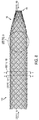
- FIG. 6 shows an illustration of a woven retention device having a tapered end, according to an embodiment of the present invention.
- FIG. 7 shows a two-over/two-under monofilament/monofilament weave of a woven retention device, according to an embodiment of the present invention.
- FIG. 8 shows a woven retention device with a tapered end along its longitudinal axis, according to an embodiment of the present invention.
- FIG. 9 shows a close-up view of a portion of the woven retention device shown in FIG. 8 .
- FIG. 10A shows a cross-sectional view along line A-A in FIG. 8 of the woven retention device.
- FIG. 10B shows a cross-sectional view along line B-B in FIG. 8 of the woven retention device.
- FIG. 11A shows an end view of the woven retention device of FIG. 8 as seen from a non-tapered end view.
- FIG. 11B shows an axial view of the woven retention device of FIG. 8 as seen from a tapered end view.
- FIG. 12A shows a tapered end of a woven retention device having a closed end, according to an embodiment of the present invention.
- FIG. 12B shows a distal end view of the closed end of the woven retention device shown in FIG. 12A .
- FIG. 13 shows a section of a woven retention device, illustrating a representative fiber angle, according to an embodiment of the present invention.
- FIG. 14 shows a section of a woven retention device, illustrating another representative fiber angle, according to an embodiment of the present invention.
- FIG. 15 shows a section of a woven retention device illustrating multiple locations and/or points of contact on an exterior surface of the woven retention device, according to an embodiment of the present invention.
- FIG. 16A shows a representation of a woven retention device with a force or pressure applied to a location and/or point on an inside of the retention device, according to an embodiment of the present invention.
- FIG. 16B shows a view of a region of an interior surface of the woven retention device at the point shown in FIG. 16A .
- FIG. 16C shows a view of a region of an exterior surface of the woven retention surface at the point shown on FIG. 16A .
- FIGS. 17A and 17B show perspective views of two woven retention devices each having different lengths, according to embodiments of the present invention.
- FIGS. 17C and 17D show two woven retention devices each having different lengths, according to embodiments of the present invention.
- FIGS. 17E, 17F and 17G show a woven retention device in a relaxed state, in a stretched state, and in an implanted state, respectively, according to embodiments of the present invention.
- FIG. 18 shows an exploded view of a screw, a woven retention device and a pedicle hole, according to an embodiment of the present invention.
- FIG. 19 shows a close-up perspective view of an exterior surface of the woven retention device according to an embodiment of the present invention.
- FIG. 20 shows a perspective view of a section of a woven retention device having differently-shaped diameters of monofilaments according to an embodiment of the present invention.
- FIG. 21 shows a woven retention device having differently-shaped diameters of monofilaments according to an embodiment of the present invention.
- FIG. 22 shows a flow diagram of a method of utilizing a woven retention device in an embodiment, in accordance with the principles of the present invention.
- FIG. 23 shows a pullout strength comparison for a screw, a screw in a stripped bone hole, and a woven retention device with screw in a stripped bone hole, according to an example of an embodiment of the present invention.
- FIG. 24 shows a pullout force versus hole diameter for a screw and a screw with a woven retention device, in accordance with the principles of the present invention.
- FIG. 25 shows another pullout force versus hole diameter for a screw and a screw with a woven retention device, in accordance with the principles of the present invention.
- FIG. 26 shows another pullout force versus hole diameter for a screw and a screw with a woven retention device, in accordance with the principles of the present invention.
- FIG. 27 shows pullout forces measured for woven retention devices of varying construction pulled from a first material, according to examples of embodiments of the present invention.
- FIG. 28 shows pullout forces measured for woven retention devices of varying construction pulled from a second material, according to examples of embodiments of the present invention.
- the devices, systems and methods described herein may be used in the area of orthopedics and, in particular, orthopedic repairs. These include various devices, systems and methods directed to fixing and/or retaining fasteners in orthopedic applications. Fixing or retaining fasteners to bone tissue is complicated by the underlining bone tissue. Understanding that an underlying cause of failure with internal fixation in bone tissue is the bone, the devices, systems and methods described herein provide for solutions that address the implant site. At the implant site, the hole and the bone benefit from an enhanced interface.
- fixation and/or retention devices, systems and methods described herein maximize fixation and/or retention in the bone tissue, including, osteoporotic bone, bone of a poor quality, and mechanically poor bone in addition to healthy bone tissue.
- the fixation and/or retention devices, systems and methods described herein may be used with any type of fixation including, any types of screws.
- the devices, systems and methods described herein enhance the interaction of a bone anchor to a bone hole to provide enhanced fixation. Additionally, the devices, systems and methods may repair the surface of the bone hole following damage to the bone hole as in the case of stripping of the hole in the bone when a bone screw is over-tightened. Also, the devices, systems and methods provide for an enhanced bone hole surface for the reattachment of tendons in, for example, anterior/posterior cruciate ligament repair procedures, rotator cuff repair procedures, etc. The devices enhance the surface of a bone hole to enhance fixation of a bone anchor to bone and permits bone ingrowth into its structure. The devices enhance the interaction between the surface of a bone hole and the fixation device.
- the devices interdigitate with the bony structure and interact with the fixation device.
- the device alone, as a single device, enhances the surface of a bone hole to enhance fixation of a bone anchor to bone and accommodates variations in the diameter and depth of the bone hole.
- the devices, systems and methods can enhance fixation without requiring the use of cement and/or adhesives.
- FIGS. 1A and 1B show a woven retention device 100 for interfacing with a bone surface 104 , according to an example of an embodiment.
- the retention device 100 may have a general configuration or construction in the form of a hollow tubular shape shown as a sleeve body 106 including a plurality of interwoven filaments that may form a substantially tubular lattice.
- the general configuration of the hollow tubular shape can be selected to accommodate a typical shape of a pilot hole in bone, for example.
- Various configurations of the sleeve body 106 can be contemplated in accordance with the principles of the invention.
- the lattice may include a plurality of protuberances distributed on an interior surface 110 and an exterior surface 108 of the lattice at a predetermined spatial relationship.
- Each of the plurality of protuberances may be formed by an intersection of filaments. More particularly, each of the plurality of protuberances may be formed by an intersection point of two or more of the plurality of interwoven filaments. The intersection can be referred to as a location and/or point. Additionally, the interwoven filaments may outline interstices that allow for bone ingrowth.
- the woven retention device can also have a proximal end 114 that is proximal to the sleeve body 106 and that is configured to receive at least a portion of a fastener 102 such that the sleeve body 106 may surround at least a portion of the fastener 102 when inserted therein.
- the woven retention device 100 can also have a distal end 116 that is distal to the sleeve body 106 .
- the distal end 116 is formed to ease insertion of the woven retention device 100 into the bone hole 101 .
- the distal end 116 in FIG. 1A is tapered.
- the lattice can be a tubular lattice.
- the woven retention device 100 can be inserted into a hole in a bone and interact with both the bone and a screw. While the woven retention device 100 can achieve an interference fit functionality by providing additional interference in between the fastener and the bone, in some embodiments, the woven retention device can instead of and/or in addition to function as a woven retention device in accordance with the configurations, functions and advantages that are discussed herein.
- the woven retention device can have a dual interface between a radial screw surface on one side and multiple points of contact on a bone surface on the other side.
- the dual interfaces on the retention device are configured to be adapted to the bony structure on the outside and the screw on the inside, as described herein in accordance with the principles of the invention.
- the woven retention device can be particularly beneficial for osteoporotic or weakened bone that has more space gaps than normal bone to allow additional points of contact for the interface to contact.
- FIG. 1A shows the woven retention device 100 in an exploded state with the fastener 102 outside of the retention device, and both the fastener 102 and the retention device 100 are outside of the bone hole.
- FIG. 1B shows the fastener 102 inside the woven retention device 100 , which is inside the bone.
- FIGS. 1A and 1B also illustrate an example of a porous interior structure of the bone.
- embodiments of the invention are not limited to being used with the exact porous structure shown, as the structure and porosity of bone can vary.
- the bone illustrated in FIGS. 1A and 1B resembles a human femur, embodiments of the invention are not limited to a particular bone.
- An advantage of some embodiments of the invention is that a woven retention device can be provided for use in a variety of bones and bones exhibiting varying levels of porosity.
- FIG. 2A shows a sleeve body 106 to be inserted into a bone hole 101 in a bone 103 .
- the distal end 116 tapers to a distal tip 115 that has a smaller diameter than the sleeve body 106 .
- the tapering at the distal tip 115 can ease insertion of the woven retention device 100 into the bone hole 101 .
- the diameter of the sleeve body 106 may be equal to or larger than a diameter of the bone hole 101 , and the tapering at the distal tip 115 can allow the distal end 116 to find its way into the bone hole 101 .
- a remainder of the woven retention device 100 can more easily be inserted into the bone hole 101 , and, in a case where the diameter of the sleeve body 106 is larger than the diameter of the bone hole 101 , the woven retention device 100 can compress radially as the sleeve body 106 is inserted into the bone hole 101 .
- the tapering of the distal end 116 and smaller diameter of the distal tip 115 can provide a surface on the interior of the woven retention device 100 for pushing against with a push rod to insert the woven retention device 100 into the bone hole 101 , according to some embodiments.
- the woven retention device 100 may be in a first, relaxed state at the position shown in FIG. 2A . During or after insertion into the bone hole 101 , however, the woven retention device 100 may also assume a radially contracted or radially expanded state.
- the plurality of interwoven filaments are visible in FIG. 2A .
- these filaments may include one or more varieties of filament shapes and sizes such that the sleeve body 106 can have a plurality of combinations of filament cross-section geometries at the intersection of the filaments, which can also be referred to as intersection points of the filaments.
- the plurality of combinations of filament cross-section geometries may form a plurality of protuberance thicknesses, each thickness being measured in a radial direction of the sleeve body 106 .
- a cross-section geometry can include a shape of the cross-section and/or a size of the cross-section.
- the combination of the filament cross-section geometries can include the cross-section geometries of both filaments at the intersection.
- FIG. 2B shows a simplified schematic cross-section of the bone hole 101 and the woven retention device 100 inserted therein.
- the undulating lines representing the sides of the woven retention device 100 in FIG. 2B may represent the plurality of protuberances 150 o , 150 i on the exterior and interior, respectively, of the woven retention device 100 by the series of peaks formed on the respective walls of the woven retention device 100 .
- the woven retention device 100 is adapted to receive the fastener 102 .
- the fastener 102 can be a screw having a winding protrusion 118 , such as a thread of a screw.
- the woven retention device 100 can be configured such that when the protrusion 118 applies pressure to a protuberance on the interior surface, the pressure is transmitted to protrusions on the exterior surface extending around the protrusion on the interior surface and exerting pressure on bone material.
- Embodiments of the invention are not limited to being used with a screw-type fastener.
- the fastener may be a nail, rod, prosthetic, or other device for implanting at least partially in a bone.
- a biological material or structure, such as a ligament may be inserted into the woven retention device.
- FIGS. 2C and 2D show that in a second state, when surrounding at least a portion of the fastener 102 , the sleeve body 106 is configured to engage the bone 103 surrounding the bone hole 101 , and may distribute pressure from the fastener 102 to multiple points of contact on the exterior surface of the woven retention device 100 such that the spatial relationship of the plurality of protuberances may change.
- the spatial relationship of the plurality of protuberances may change as a function of bone density of the bone surface 104 .
- FIG. 2C shows a bone 103 that is more dense than the bone 103 ′ of FIG. 2D .
- the woven retention device 100 is displaced more prominently in the less dense surface of FIG. 2D than the denser bone surface of FIG. 2C .
- This displacement of the woven retention device 100 corresponds to a change in the spatial relationship of the plurality of protuberances (the protuberances themselves are not shown in the simplified schematic view of FIGS. 2C and 2D ) on the exterior surface, which can allow for greater interdigitation of the woven retention device 100 with the bone surface.
- the force from the protuberances on the exterior surface changes the shape of the bone. It is noted that the illustration of the bones 103 and 103 ′ in FIGS. 2C and 2D are simplified schematic representations.
- the surfaces of the bones 103 and 103 ′ that are engaged by the woven retention device 100 may be irregular, including a series of voids and projections, for example. Accordingly, the variation in displacement of the sides of the woven retention device 100 when the fastener 102 is inserted can accomplish improved engagement between the woven retention device 100 and the bone 103 (and correspondingly provide the fastener 102 with greater purchase in the bone).
- the spatial relationship of the plurality of protuberances can also change as a function of loading and/or the fastener.
- the spatial relationship of the plurality of protuberances can change as a function of an interfacing surface shape of the fastener 102 .
- the fastener 102 can be a screw.
- the screw can be a cancellous screw.
- the screw can be a cortical screw.
- the screw can have crests 124 that are the most outwardly protruding portions of the thread of the screw and can have valleys 136 , which are the innermost portions of the screws.
- the screw can have various levels of coarseness of the threads, representing larger pitch (fewer threads per axial distance).
- the retention device when interfacing with the screw can change to accommodate the coarse threads.
- the retention device can adapt to follow the crests 124 and the valleys 136 to create a general wave pattern.
- the retention device in the case of a smaller diameter screw, or a finer thread with smaller pitch, the retention device can deform or bend over the peaks of the threads less.
- the absolute value of pullout resistance can be greater with a larger screw but the delta between the differential can be smaller with the larger diameter screw because of additional interwinding of the intermediary point of contact.
- the protuberances on the exterior surface do not interface as much with the bone because of some of the protuberances folding inward because of the coarseness of the thread.
- the woven retention device can move more uniformly, which can allow for greater interdigitation. Thus, because there can be less chance for those interdigitation points to reach into the valleys of the threads, there is more interaction with the bony surface.
- the spatial relationship of the plurality of protuberances can also change as a function of an interfacing surface shape based on the length of the surface.
- the surface of the fastener 102 can also be various lengths.
- the change in pullout resistance can be greater with large screws than small screws in total pullout resistance
- the small screw can have greater pullout resistance as a measure of percent change.
- One factor that affects the small screw having a greater pullout resistance in percent change is that more interaction with the woven retention device 100 can be possible with a smaller fastener as a percentage of the fastener's percentage of coverage. This can result in a larger differential in pull out resistance in the smaller sizes than there is in the larger sizes because of the increased interaction.
- the mechanical properties of the woven retention device can compensate for differences in the fastener surface. For example, to increase bone surface interaction with a fastener 102 that has a coarse thread, a woven retention device with a greater level of stability can be used to prevent the filaments from retreating too far into the valleys 136 and instead interacting with the bone surface.
- the woven retention device 100 may be specifically configured for a bone of a particular density or range of densities.
- the structural configuration, material properties, or other aspects of the woven retention device may be adjusted to provide desired engagement with the bone surface of a particular density or range of densities.
- a particular woven retention device may be suitable for use in bones of varying densities.
- FIG. 3A shows an alternative schematic representation of a cross-section of the woven retention device 100 , according to an embodiment.
- the cross-section of the woven retention device in FIG. 3A reveals an example of the constituent filament cross-section geometries 121 A, 121 B, 121 C that contribute to the protuberances 150 A o , 150 B o , 150 C o , 150 A i , 150 B i , 150 C i of the woven retention device 100 .
- At least one filament 112 C can be seen weaving over and under adjacent filaments 112 A, 112 B with substantially circular cross-sections.
- Outer diameter OD 1 can be a distance from an outermost protuberance on the exterior surface of one side to a protuberance on the exterior surface on the opposing side.
- inner diameter ID 1 can be a distance from an innermost protuberance on the interior surface of one side to an innermost protuberance on the interior surface of an opposing side. The relationship between the outer diameter OD 1 and the inner diameter ID 1 can be based on the thickness or diameter of the filaments.
- FIG. 3B shows an alternative fastener 202 that interfaces with the woven retention device 100 .
- the fastener 202 changes the spatial relationship of the protuberances (e.g., protuberances 150 o ) from the spatial relationship in FIG. 3A .
- outer diameter OD 2 can still be a distance from an outermost protuberance on the exterior surface of one side to a protuberance on the exterior surface on the opposing side
- inner diameter ID 2 can still be a distance from an innermost protuberance on the interior surface of one side to an innermost protuberance on the interior surface of an opposing side
- a change in the spatial relationship can result in a larger inner diameter ID 2 and outer diameter OD 2 .
- the OD 2 distance can be a distance larger than outer diameter OD 1 .
- the distance ID 2 can be larger than the distance ID 1 .
- the amount of change of the spatial relationship of the protuberances may change based on the alternative constructions of the fasteners 102 and 202 in FIGS. 2C and 3B , respectively.
- bone screws are provided in various size and types, which may have different minor diameters, major diameters, thread pitches, pitch diameters, and lengths.
- the change in the spatial relationship of the protuberances between FIGS. 3A and 3B can be, in one embodiment, understood as a radial expansion of the woven retention device 100 upon insertion of a fastener therein.
- This radial expansion can be substantially uniform, as indicated by the uniform displacement of the woven retention device 100 from ID 1 , OD 1 in FIG. 3A to ID 2 , OD 2 in FIG. 3B .
- the spatial relationship between the protuberances on the surface of the woven retention device changes (i.e., the protuberances may spread apart from one another like points on the surface of an inflating balloon).
- the woven retention device 100 may not expand uniformly when in the bone hole 101 .
- the change in spatial relationship of the protuberances may not be uniform, and may instead include localized changes in the protuberance dispositions.
- Such localized changes may occur in multiple areas of the woven retention device and may include varying degrees of disposition changes between different areas of the retention device. This capability and/or flexibility provided by some embodiments of the present invention may provide for better bone engagement and fastener retention.
- FIG. 3C shows the different radial pressures that can be applied when the fastener 202 is inserted into the woven retention device 100 , which is disposed in the bone 103 .
- the outward radial pressure supplied by the fastener alters the disposition of the woven retention device 100 , as discussed above.
- pressure P 1 is exerted between the retention device 100 and fastener 202 .
- corresponding pressure P 2 is exerted between the retention device 100 and the bone 103 from the pressure transferred by the retention device 100 from the fastener 202 .
- the woven retention device 100 is a dual-interface.
- the dual interface includes an inner, fastener-retention device interface and an outer, retention device-bone interface. These two interfaces work in conjunction to provide improved fastener retention and holding power in the bone.
- FIG. 3D shows a schematic axial view of the retention device 100 and fastener 202 that are shown in FIG. 3C .
- FIG. 3D shows space between the fastener 202 and an inside of the woven retention device 100 , and thus FIG. 3D is not to scale. From the perspective in FIG. 3D , it can be appreciated that the pressures P 1 and P 2 can radiate in all directions with respect to a center of the woven retention device 100 .
- a pressure P 1 exerted between the fastener 202 and an interior protuberance 150 i can be transferred through the woven retention device 100 to multiple exterior protuberances 150 A o and 150 B o to exert pressure P 2 at multiple points of contact with the bone.
- FIG. 4 shows a side view of a fastener 102 inside of a retention device 100 and inside a bone hole 101 , according to an embodiment of the present invention.
- Longitudinal forces F L can act between interdigitated portions of the retention device (e.g., the protuberances 150 i , 150 o ) and the bone surface 151 , and between the retention device 100 and the fastener 102 .
- These longitudinal forces can act to prevent pullout of the fastener 102 , which can add to the resiliency of the fastener 102 in the longitudinal direction.
- FIG. 4 also shows a gap 113 between the exterior surface 108 of the woven retention device 100 and the bone surface 151 .
- the gap 113 may be smaller or larger depending on the porosity of the bone 103 , the configuration of the woven retention device 100 , and the characteristics of the fastener 102 .
- FIG. 5A shows a woven retention device 1005 according to an embodiment of the invention.
- the interwoven filaments of the woven retention device 100 can include a first plurality 123 of sets of filaments 120 ( FIG. 6 ) that runs in a first helical direction and a second plurality 125 of sets of filaments 122 ( FIG. 6 ) that runs in a direction intersecting the first plurality 123 of sets of filaments.
- each intersection of the first plurality 123 of sets of filaments with the second plurality 125 of sets of filaments may result in an arrangement of one or more cross-section geometries.
- the arrangement of the one or more cross-section geometries has a substantially same arrangement of cross-section geometries, and at other intersections along that set of either one of the first or second plurality 123 , 125 of sets of filaments, there is a substantially different arrangement of cross-section geometries.
- the sets of filaments have a degree of stability and rigidity to form a tubular lattice in the relaxed state.
- the flexibility and stability of the tubular lattice may be such that the woven retention device 100 is able to return to an initial state from a deformed state.
- the deformed state may be the result of the woven retention device being in compression or tension either radially or longitudinally, and the deformation may be elastic deformation.
- FIG. 5B shows one embodiment of the plurality of combinations of filament cross-section geometries forming a plurality of protuberance geometries of the retention device shown in FIG. 5A .
- the geometries may include, for example, shape, configuration, arrangement, and/or thickness of the filament(s) and/or the protuberance(s).
- a first thickness 302 represents the thickness of an intersection of two filaments 310 , 312 , each having a relatively small thickness. In some embodiments, this intersection maybe formed by monofilament 310 overlapping another monofilament 312 .
- monofilament 310 can have a same diameter as monofilament 312 . However, in another embodiment, the monofilament 310 can have a different diameter than monofilament 312 .
- a second thickness 304 represents the thickness of an intersection of two filaments 310 , 314 , the filament 310 having a relatively small thickness and the filament 314 having a relatively large thickness.
- this intersection may be formed by a multifilament ( 310 ) overlapping a monofilament ( 314 ).
- filament 310 can be a monofilament having a smaller diameter than monofilament 314 .
- intersection 304 can be formed by a monofilament 310 overlapping a monofilament 314 .
- a third thickness 306 represents the thickness of an intersection of two filaments 312 , 316 .
- this intersection may be formed by a multifilament ( 312 ) over a monofilament ( 316 ).
- filament 312 can be a monofilament having a thinner diameter than monofilament 316 .
- the third thickness 306 can be formed by an intersection of monofilament 312 overlapping monofilament 316 .
- the thicknesses 304 and 306 may have a same thickness if the filaments 310 and 312 have a same thickness, and the filaments 314 and 316 have a same thickness.
- the thicknesses of filaments 310 and 312 may be different, and the thickness of filaments 310 and 312 may be different, while the thicknesses 304 and 306 may be the same or different.
- a fourth thickness 308 represents the thickness between two relatively thick filaments 314 , 316 .
- this intersection may be formed by a monofilament 314 overlapping a monofilament 316 .
- each of the protuberance geometries and/or thicknesses 302 , 304 , 306 , 308 allow for interfacing with the fastener on one side and the bone on the other side, and distributing pressure outwardly from the fastener to the bone in a distributed manner.
- monofilament 314 can have a same diameter as monofilament 316 .
- the monofilaments 314 , 316 can have different thicknesses.
- the tubular lattice of the woven retention device 100 may have an outer radius spanning from a furthest outwardly extending protuberance in the radial direction on the exterior surface of the tubular lattice to a center point and/or central axis of the tubular lattice, the tubular lattice having an inner radius spanning from a furthest inwardly protruding protuberance in the radial direction on the interior surface of the tubular lattice to the center point of the tubular lattice.
- the tubular lattice may have an average radius that is an average between the outer radius and the inner radius.
- the outer radius of the woven retention device 100 is greatest at the cross-section geometries that have the greatest protuberance thicknesses.
- the inner radius of the woven retention device 100 may be the smallest at the cross-section geometries that have the largest protuberance thicknesses.
- distributed protuberances on the outer surface can have more than two different heights in relation to the distance from a center point of the cross-section of the tubular lattice to peaks of the distributed protuberances on the exterior surface. Further, the distributed protuberances on the exterior surface can have more than two different angles of protrusions, or amplitudes, where the amplitude of a monofilament overlying a monofilament has a higher amplitude than where the monofilament overlies a multifilament.
- the angle, protrusion, and/or curvature of the multifilament overlying a monofilament is greater than that of a multifilament overlying a multifilament because the variance or the steepness of the curve of the multi-filament is greater.
- the filaments, density, and/or pick count can contribute to the difference in the sharpness, angle and/or amplitude of the protrusions. The more pronounced the protrusion, the sharper the protrusion can be considered.
- Various relationships between the diameter of the retention device, the thickness of the first filament(s) and, the thickness of the overlying filament(s), and the weave pattern contribute to the resulting protuberances and protuberance geometries.
- Varying the protuberances and protuberance geometries can provide for woven retention devices having predetermined protuberances that accommodate various bony structures.
- the different heights and angles of distributed protuberances on the exterior surface can allow for interdigitation with bone surfaces, especially if the bone surface is irregularly shaped.
- pressure from the fastener can be transmitted to the tubular lattice such that at least one of (i) the heights of the protuberances on the exterior surface, (ii) the amplitudes of the protuberances on the exterior surface, and (iii) the ratio of the height to the average radius, can change to accommodate deviations in the bone surface.
- FIG. 6 shows a woven retention device according to an embodiment where a distal end 116 of the woven retention device 100 has a distal tip 115 with a first diameter D 1 , and the receiving portion has a second diameter D 2 that is greater than the first diameter D 1 .
- a diameter D 2 of the proximal end 114 is substantially same as a diameter of the sleeve body 106 .
- the embodiment shown in FIG. 6 may have the distal end 116 tapered.
- a set 120 of the first plurality 123 of sets of filaments includes a monofilament 126 and a monofilament 128 (as shown in FIG. 7 ).
- a set 122 of the second plurality 125 of sets of filaments includes a monofilament 132 and a monofilament 130 (as shown in FIG. 7 ).
- the woven retention device 100 can include up to ten sets of filaments in each of the first and second plurality 123 , 125 of sets of filaments.
- the woven retention device 100 can include at least two sets of filaments.
- each of the sets of filaments may have a degree of flexibility that allows for expandability of the woven retention device 100 .
- the filament properties and characteristics can be varied, and the number of filaments used in the weave contributes to the stability and/or rigidity of the woven retention device.
- a small-sized woven retention device may include a half set of filaments such as 12 filament in one direction and 12 in the other direction.
- a larger size may weave 24 filaments and 24 filaments.
- a range of the quantity of filaments can vary from 2/2 to 36/36.
- the quantity of filaments can be 8/8, 10/10, 12/12, 24/24 and/or 36/36, according to some embodiments.
- other filament quantities are also possible.
- An even number of filaments and bobbins are contemplated, resulting in a symmetrical pattern. But an odd number of filaments can be utilized as well and would result in a non-symmetrical pattern.
- FIG. 7 shows a close-up of the woven retention device 1007 according to an embodiment having a combination of different filaments.
- the filaments can be of different shapes and diameters.
- the filaments can be a combination of round filaments and flat filaments, or all flat filaments, or all round filaments.
- the shapes of the filaments are not limited to flat and round, however, and may also include rectangular, triangular, and elliptical shapes, or other cross-section shapes.
- the woven retention device has flat multifilaments 142 and round monofilaments 140 .
- filament 142 can be a monofilament having a different or the same diameter as monofilament 140 .
- the flat multifilaments 142 have a larger width than height.
- the round monofilaments 140 can have a substantially circular cross-section.
- the round monofilaments 142 can have a substantially circular cross-section.
- the thickness of the monofilaments 140 is greater than the thickness of the multifilaments 142 .
- different types of filament intersections can be provided. For example, each of intersections 144 , 145 , 146 , and 147 can comprise a different arrangement and/or combination of filaments, as discussed further below.
- a set 120 of the first plurality 123 of sets of filaments includes a set 120 including a monofilament 126 and a monofilament 128 having different or the same diameters.
- the set 120 of the first plurality 123 of sets of filaments can include a monofilament and a multifilament.
- a set 122 of the second plurality 125 of sets of filaments includes a monofilament 132 and a monofilament 130 having the same or different diameters.
- the set 122 of the second plurality 125 of sets of filaments can include a monofilament and a multifilament.
- FIG. 8 shows the woven retention device 1008 with a tapered distal end 116 along its longitudinal axis.
- FIG. 9 shows a close-up view of the woven retention device 1008 of FIG. 8 , according to one embodiment.
- a set of filaments can include one or more filaments.
- a set of filaments can include filaments that are side by side and the filaments including an inner filament and an outer filament.
- the inner filament in one embodiment can be disposed on the left of the outer filament, as viewed facing the receiving portion in a longitudinal direction.
- FIG. 9 shows one embodiment of a woven retention device 1008 , wherein each of the first plurality 123 ( FIG. 5A ) of sets of filaments 120 includes a first inner filament 126 and a first outer filament 128 , and each of the second plurality 125 ( FIG.
- the woven retention device 1008 is configured such that the plurality of interwoven filaments are comprised of alternating round monofilaments and flat multifilaments.
- each of the sets of filaments can have a consistent and uniform order of filaments, which allows for a uniform arrangement of protuberances.
- the plurality of interwoven filaments are comprised of alternating round monofilaments of a first diameter and round filaments of a second diameter that is greater than or less than the first diameter.
- the first inner filament 126 can be a flat multifilament 142
- the first outer filament 128 can be a round monofilament 140
- the second inner filament 132 can be a flat multifilament 142
- the second outer filament 130 can be a round monofilament 140
- the first inner filament 126 can be a round monofilament 140
- the first outer filament 128 can be a flat multifilament 142
- the second outer filament 130 can be a flat multifilament 142
- the second inner filament 132 can be a round monofilament 140 .
- first inner filament 126 can be a flat multifilament 142 and the first outer filament 128 can be a flat multifilament 142 while the second outer filament 130 can be a round monofilament 140 and the second inner filament 132 can be a round monofilament 140 .
- the first inner filament 126 can be a round monofilament 142
- the first outer filament 128 can be a round monofilament 140 having the same or different diameter as monofilament 142
- the second inner filament 132 can be a round monofilament 142
- the second outer filament 130 can be a round monofilament 140 having a same or different diameter as round monofilament 142 .
- the protuberances form a diamond arrangement shown by the shape defined by intersection points 144 ′, 145 ′, 146 ′, and 147 ′.
- the first inner filament 126 and the second outer filament 130 being monofilaments results in a pronounced protuberance (e.g., a protuberance having the thickness 308 in FIG. 5B ) to occur at a top intersection point 144 of a diamond arrangement of the combination of intersections, the diamond arrangement being defined by the shape outlined by intersection points 144 , 145 , 146 , and 147 .
- the woven retention device 1008 can be configured so that the plurality of interwoven filaments follow a two-under/two-over configuration, where each of the filaments overlie two intersecting filaments and underlie two intersecting filaments.
- a round monofilament either overlies both of the intersecting filaments or is overlain by both of the intersecting filaments and the flat multifilament overlies one of the intersecting filaments and is overlain by the other of the intersecting filaments.
- other contemplated embodiments include a one-over-one weave provided that there is sufficient rigidity and flexibility of the filaments to generate the protuberances.
- a one-over/one-under configuration is contemplated where each filament alternatingly overlies and underlies an intersecting filament.
- a three-over/three-under weave pattern is contemplated where each filament overlies three intersecting filaments before underlying three intersecting filaments.
- a two-over/one-under is contemplated where each filament overlies two intersecting filaments and then underlies one intersecting filament.
- a one-over/two-under arrangement is also possible where a filament overlies one intersecting filament before underlying two intersecting filaments.
- a three-over/one-under is contemplated where each filament overlies three intersecting filaments and then underlies one intersecting filament.
- a one-over/three-under arrangement is also possible where a filament overlies one intersecting filament before underlying three intersecting filaments.
- FIGS. 10A and 10B show cross sections showing the intersecting filaments of the woven retention device 1008 , representing various cross-sectional geometries 149 at the sections A-A and B-B indicated in FIG. 8 .
- the woven device 1008 can be configured as shown such that the intersecting sets of filaments form a plurality of cross-sectional geometries and/or thicknesses.
- section A-A of FIG. 8 the large round over round grouping represents the intersection of a relatively large round monofilament 142 over another relatively large round monofilament 142 .
- the cross-sections of these relatively large round monofilaments 142 , 142 can be the same or have different thicknesses from each other.
- the smaller round-over-round grouping represent a relatively small round monofilament 140 over another relatively small round monofilament 140 intersection where the round monofilaments 140 , 140 can have the same or different thicknesses from each other.
- the large circle over the small circle grouping represents a round monofilament 142 over a round monofilament 140 where the diameter of round monofilament 142 is greater than round monofilament 140 .
- a small circle over large circle cross-section geometry represents a round monofilament 140 over a round monofilament 142 where the diameter of the round monofilament 140 is smaller than round monofilament 142 .
- the round monofilaments of the woven retention device can have differing diameters.
- the round monofilaments can have a diameter in a range of about 0.1 mm-0.4 mm. In one embodiment, the round monofilament of the woven retention device is 0.2 mm.
- the multifilaments of the woven retention device can have various thicknesses and widths.
- a multifilament may have a thickness of less than 0.1 mm.
- the cross-sectional shape, e.g., flat or round, and the texture, for example, of the multifilaments can also be relevant.
- the number of filaments and pattern can also be relevant.
- various filament linear mass densities can be contemplated.
- the multifilaments can have a linear mass density in a range of about 150-250 denier. In one embodiment, the multifilaments can have a linear mass density of about 200 denier.
- the woven retention device can be configured such that the intersecting sets of filaments form a plurality of differently shaped and differently sized interstices.
- the first inner and outer filaments of one set of first filaments can be grouped closer to each other than the other sets of first filaments.
- the second inner and outer filaments of one set of second filaments can be grouped closer to each other than the other sets of second filaments.
- a more conducive environment for non-uniform bony surface can allow for ingrowth of bone to occur. Additionally, improved interdigitation with the bony structure can be achieved with a combination of the interstices and protuberances.
- the tapering end portion can be seen from FIGS. 11A and 11B a front and rear axial direction of the woven retention device 1008 , as indicated in FIG. 8 .
- An edge of the distal tip 115 can be seen in FIGS. 11A and 11B from inner and outer sides, respectively, the distal end 116 (see FIG. 8 ).
- the tapered end can be used to facilitate inserting the woven retention device 1008 into a bone hole.
- the tapered end can have at least a portion of the end be closed. As shown in FIGS.
- a distal end 116 ′ of a woven retention device has a distal tip 115 ′ that can be closed to further allow for a push rod to push the woven retention device 100 into the hole.
- the closure of the end can be made (i.e., tip can be made) via knitting, energy (heat stake, laser, optical, ultrasound energy to melt fibers), and chemical (glue, or superglue).
- the interwoven filaments of a woven retention device 10013 extend around the tubular lattice in an angle range of ⁇ .
- ⁇ can represent a range from about 40-60 degrees with respect to a longitudinal direction of the woven retention device.
- ⁇ can represent a range from about 15-75 degrees with respect to a longitudinal direction of the body sleeve.
- ⁇ represents 45 degrees.
- the retention device can, in the relaxed state, have the interwoven filaments that extend around the tubular lattice at about a 45 degree angle with respect to a longitudinal direction of the woven retention device.
- the configuration and angle ⁇ shown in FIG. 13 can correspond to a relaxed state of the woven retention device 100 according to some embodiments.
- FIG. 14 shows that the braid angle ⁇ for a woven retention device 10014 , according to another embodiment.
- the braid angle ⁇ can be smaller than 45 degrees.
- the configuration and braid angle ⁇ in FIG. 14 can also represent the woven retention device 10013 of FIG. 13 in a constricted state or if the woven retention device 10014 has a predetermined diameter lower than a predetermined value and the filaments exceed a predetermined thickness. For example, when the woven retention device has an average diameter of 2 mm, the braid angle ⁇ can be about 35 degrees.
- FIG. 15 shows the distributed protuberances 150 on the exterior surface of the woven retention device 10015 according to an embodiment.
- the woven retention device 10015 can allow for a different loading pattern (dynamic load) than the screw because of uniform radial pressure. Instead of pushing or cutting bone, the screw can push on and deform the woven structure of the woven retention device 10015 , which allows for a distributed force.
- the woven structures can be of a strength to not be cut or broken by the screw.
- the interface can be in random or patterned contacts on the exterior surface and the interior surface.
- FIG. 15 shows that the protuberances 150 are in a substantially diamond-shaped pattern grid distributed across the tubular lattice.
- FIG. 16A is a cross-sectional schematic of the retention device (in the shape of a general circle) having an arrow representing a point of pressure contact on the interior surface 110 of the woven retention device 100 .
- FIG. 16B represents a portion of the interior surface 110 covering the bracketed portion of FIG. 16A as viewed from inside the woven retention device 100 .
- FIG. 16C represents a reverse view from that of FIG. 16B , and thus shows an outer surface as evidenced by bracket in FIG. 16A as viewed from outside of the woven retention device 100 looking in to the radial center.
- Intersections points Xi 1 , Xi 2 , Xi 3 , and Xi 4 on the interior surface 110 in FIG. 16B respectively correspond to intersection points Xo 1 , Xo 2 , Xo 3 , and Xo 4 on the exterior surface 108 in FIG. 16C .
- each portion can appear the same. That is, while an over/under weave on a left side of the interior surface can correspond to a under/over weave on a right side of the exterior surface, the left portion in a similar position as the left portion of the interior surface can resemble a similar configuration of the over/under weave.
- Each of the four Xi regions in FIG. 16B corresponds to a protuberance on the interior surface, and the filaments F 1 and F 2 can correspond to intersecting multifilaments. When viewed from the exterior surface, this same portion shows that the pressure is located on the right side of the portion.
- filament F 1 overlies filament F 2 at intersection Xi 1
- filament F 2 overlies filament F 2 at intersection Xo 1
- the left portion of the exterior surface it resembles the left portion of the interior portion.
- the woven retention device In a relaxed state, the woven retention device can be of various lengths and diameters.
- FIGS. 17A and 17B show that two differing lengths of embodiments of woven retention devices 10017 A and 10017 B, respectively.
- the woven retention device can have a length in a range of about 30 mm to 40 mm.
- the length of the woven retention device can come in dynamically cuttable; and/or predetermined length, such as small—30 mm; medium—40 mm, large—40 mm, and other sizes (or ranges) are also possible.
- FIGS. 17C and 17D show two embodiments of woven retention devices 10017 C and 10017 D with differing lengths and each with a diameter that is different from FIGS. 17A and 17B .
- the woven retention device can have a diameter of about 1.5 mm to 9.0 mm.
- the diameter of the woven retention device can come in predetermined sizes, such as (i) small: 2.0 mm fine (can accommodate 1.3 mm to a little over 2.0 mm pilot hole diameter and can fit 2.0 mm-2.7 mm screws); (ii) medium: 3.5 mm-6.0 mm course (can accommodate 2.4 mm to a little over 3.2 mm pilot hole diameters and can fit 3.5-6 mm screws); and (iii) large: 6.5 mm-9 mm very course (can accommodate 4.1 mm to a little over 5.9 mm pilot hole diameters and can fit 6.5-9.0 mm screws).
- FIG. 17E shows a woven retention device 100 in a relaxed state.
- FIG. 17F shows that applying pressure in a longitudinal direction stretches the woven retention device 100 such that the diameter of the woven retention device 100 decreases. In this manner, the woven retention device 100 can be easily inserted into a bone hole 101 .
- FIG. 17G shows that once inside the bone hole 101 , the woven retention device 100 can have longitudinal forces applied to return the woven retention device 100 to a less constricted shape. In this manner, it allows for the woven retention device to snugly fit into the bone hole 101 .
- the braid angles of the interwoven filaments can be larger than the braid angle in a construed or elongated state.
- the retention device allows for a maximum distribution of protuberances based on the braid angle.
- the retention device 100 in the elongated state of FIG. 17F can have less distributed protuberances than the retention device 100 in the less constricted state of FIG. 178G .
- a screw can be inserted into the woven retention device 10018 , which can then be inserted into a hole in a vertebra.
- Embodiments of the invention are not limited to being used in any particular bone, and may be configured for use in any bone.
- FIG. 19 shows a perspective view of a portion of a woven retention device 100 ′ according to an embodiment of the present invention.
- the profile of protuberances 150 ′ are shown.
- the woven retention device 100 ′ comprises a pair of monofilaments 126 ′ and 132 ′, and a pair of multifilaments 128 ′ and 130 ′.
- each of the multifilaments 128 ′ and 130 ′ has a different width or linear mass thickness.
- each of the monofilaments 126 ′ and 132 ′ have a different thickness.
- multifilament 128 ′ is wider than multifilament 130 ′
- monofilament 132 ′ is thicker than monofilament form 126 ′.
- the specific arrangement and relative thicknesses of the filaments in FIG. 19 are just examples of an embodiment. It should be understood that the monofilaments 126 ′ and 132 ′ may have the same or different relative thicknesses, and likewise for the widths or linear mass densities of multifilaments 128 ′ and 130 ′.
- FIG. 20 shows another view of the embodiment shown in FIG. 19 .
- the intersections of filaments 126 ′, 128 ′, 130 ′, and 132 ′ are shown to provide examples of the different types of intersections which can provide a plurality of combinations of filament cross-section geometries according to this embodiment.
- intersection 145 ′ represents the intersection of a monofilament 126 ′ and multifilament 130 ′.
- Intersection 146 ′ is the intersection of monofilament 126 ′ and monofilament 132 ′, which would represent the thickest protuberance according to this embodiment.
- Intersection 147 ′ is the intersection of monofilament 132 ′ and multifilament 128 ′.
- intersection 148 ′ is the intersection of multifilament 130 ′ and multifilament 128 ′, which would form the smallest intersection thickness according to this embodiment.
- the plurality of plurality of filaments include thicker monofilaments (e.g., 132 ′) wound in a first spiral direction of the woven retention device, and smaller monofilaments (e.g., 126 ′) wound in a second spiral direction of the woven retention device.
- FIG. 21 is a view of an embodiment of the woven retention device 100 ′ shown in FIGS. 19 and 20 .
- the first plurality of filaments 123 ′ including monofilament 314 ′ and multifilament 312 ′, are wound in the first direction
- the second plurality of filaments 125 ′ including monofilament 310 ′ and multifilament 316 ′, are wound in the second direction.
- FIG. 22 details steps that can be performed in conjunction with the woven retention device.
- the woven retention device may be inserted into a bone hole alone and then a fastener can be inserted.
- the woven retention device and screw can we combined prior to insertion and the combination inserted into the bone hole.
- the invention is not limited to the steps described in FIG. 22 , is not limited to the order of the steps disclosed, and does not require that certain of the disclosed steps be performed.
- a bone in step S 400 , can be drilled to form a bone hole.
- the woven retention device can be elongated or constricted in step S 402 , after which in step S 404 the woven retention device can be inserted into the bone hole.
- step S 406 the woven retention device upon entering the bone hole can be expanded.
- the fastener can be inserted into the woven retention device either before or after insertion into the bone hole.
- the fastener can exert pressure on an interior of the woven retention device in step S 410 .
- the fastener can optionally change the shape of the interior of the woven retention device.
- pressure from an interior of the woven retention device can be distributed to an exterior surface of the woven retention device.
- the shape of the exterior surface of the woven retention device can optionally change shape.
- pressure from an exterior surface of the woven retention device can transmit to bone surface.
- the pressure transmission to the bone surface can optionally change the shape of the bone surface.
- the steps can be performed in different orders or steps can be optionally omitted.
- a fastener can be inserted into the woven retention device before the woven retention device has been inserted into the bone hole, after which in step S 403 the fastener with woven retention device can be inserted into the bone hole.
- the fastener can optionally change the shape of the interior of the woven retention device.
- step S 412 pressure from an interior of the woven retention device can be distributed to an exterior surface of the woven retention device.
- the shape of the exterior surface of the woven retention device can optionally change shape.
- pressure from an exterior surface of the woven retention device can transmit to bone surface.
- the pressure transmission to the bone surface can optionally change the shape of the bone surface.
- the distributing pressure step comprises dynamic micro-loading of the woven retention device based on differences in loading patterns of the woven retention device and the interfacing surface shape of the fastener. Based on a uniform radial distribution of the woven retention device, a different loading pattern, or in other words, a dynamic load, is possible. That is, instead of solely pushing or cutting bone, the fastener can deform the woven structure. Further, based on the flexibility of the weave, the woven retention device can facilitate an even distribution of load on uneven bone structure.
- a fastener can be inserted into the woven retention device either before or after the woven retention device is inserted into the bone hole.
- the fastener can exert a pressure on an interior surface of the woven retention device, which can optionally change the shape of the interior surface.
- the pressure exerted on the interior surface of the woven retention device can distribute pressure to an exterior surface of the woven retention device, which can optionally change the shape of the exterior surface.
- the change in the exterior surface can allow for better interfacing with the bone surface based on the changes to the exterior surface.
- the bone surface can optionally change shape based on the pressure that is applied by the woven retention device.
- FIG. 23 shows a graph of examples of pullout strengths of a screw in control bone hole, a screw in a stripped bone hole, and, according to an example of an embodiment of the invention, a screw in a woven retention device in a stripped bone hole.
- a stripped bone hole is one in which a screw, for one reason or another, has lost purchase or fit.
- the bone may degrade or break to the point that the fit between the bone and the screw is lost, or part of the structure of the bone may be stripped or sheared by the screw itself, for example.
- a screw in a stripped bone hole can cause a decrease ⁇ S in the pullout strength of the screw as compared to a control screw that is in a bone hole that is not stripped.
- the woven retention device in accordance with the principles of the invention can cause an increase ⁇ W in the force required to pullout the screw as compared to the screw by itself in a stripped hole.
- the woven retention device can increase the pullout strength of the screw beyond that of a screw in a non-stripped hole, such as the control screw, including in cases where the woven retention device is used in conjunction with a screw in a non-stripped hole.
- FIG. 24 shows a graph showing examples of different pullout forces between small screws in various different pilot holes.
- the combination of the screw and woven fixation device in accordance with the principles of the invention, has more pullout force in each of the tested sizes.
- FIG. 25 shows a graph showing examples of different pullout forces between medium screws in various different pilot holes.
- the combination of the screw and woven fixation device in accordance with the principles of the invention, has more pullout force in each of the tested sizes.
- FIG. 26 shows a graph showing examples of different pullout forces between large screws in various different pilot holes.
- the combination of the screw and woven fixation device in accordance with the principles of the invention, has more pullout force in each of the tested sizes.
- the woven retention device can enhance pullout force percentage compared with a screw alone for a range of hole diameters.
- the woven retention device used with a small screw may allow for a higher percentage increase of pullout force than with medium and large screws.
- the woven retention device according to an embodiment has been shown to add at least a 10% increase in pullout strength compared with the pullout force of a screw without a woven retention device.
- the increase has been shown to be 33% to 77%, according to an example of one embodiment.
- the increase has been shown to be 10% to 72%, according to another example of an embodiment.
- the increase has been shown to be 12% to 30% according to another example of an embodiment.
- Examples of woven retention devices according to embodiments were fabricated using different combinations of filaments. Table 1 shows details of the four versions of these examples. Each version includes two types of counter clockwise filaments, and two types of clockwise filaments. “Type” refers to whether the filament is mono-filament or multi-filament. “Size” indicates the diameter (measured in millimeters) of the monofilaments, and the linear mass density (measured in decitex, or dtex, which is grams per 10,000 meters) for the multifilament. “# of Carriers” refers to the number of each filament. Version 1 is a combination of mono- and multifilaments. Version 2 is only monofilaments, where the monofilaments are all the same size.
- Version 3 is a combination of two different sizes of monofilaments.
- Version 4 is a combination of three different sizes of monofilaments.
- the woven retention devices in Versions 1-4 each had a braid angle of about 40° to 45°, and were sized to accommodate screw with an inner core diameter of about 6.5 mm (corresponding to the “large” size discussed above).
- the filaments were made of polyethylene terephthalate (PET).
- FIGS. 27 and 28 show the results of axial pullout strength using Versions 1-4 of the woven retention device in Table 1 as compared to the pullout strength of a screw without a woven retention device. Both tests used pilot holes with a diameter of 4.1 mm in polyurethane foam, and a screw with an inner core diameter of 6.5 mm and length of 40 mm. In the tests of FIG. 27 , 15 pcf rigid polyurethane foam was used. In the tests of FIG. 28 , 10 pcf rigid polyurethane foam was used. For all tests, the axial pullout strength was greater when a woven retention device was used, compared to when a screw was used without a woven retention device. Furthermore, FIGS.
- the woven retention device can be beneficial for use with low bone mineral density, which is the amount of mineral matter per square centimeter of bone that is between 1 and 2.5 standard deviations away from young normal adult.
- Low bone mineral density can include osteoporosis, osteopenia, hyperparathyroidism and/or osteomalacia.
- a notable part of the woven retention device's inner surface is its ability to engage with the screw without having a matching threaded surface on the interior in a preferred embodiment.
- the material of the woven retention device can be made of any plastic or fiber. Other materials can also be used, including metallic and natural or biological materials.
- the dual interface can be achieved through having a tube-shaped, braided retention device with sufficient rigidity, stability (returning to the woven retention device's original shape or configuration after deformation), and tensile strength when a screw can be inserted to provide sufficient sheer strength to a screw on the one side and a uniform and distributed pressure to the bone on the other side.
- the woven retention device can have a multi-filament comprising a one-under/one-over arrangement of 45 degree angle intersections and a mono filament that runs adjacent to each of the braids such that each filament goes over two other filaments before going under two filaments (2-over/2-under, twill or herringbone).
- a three-under/three-over arrangement can also be possible.
- Other types of weaves are possible (including only a monofilament) as long as there can be sufficient stability, rigidity, compressibility, sheer strength, and/or tensile strength.
- the Young's modulus can also be used to quantify the woven retention device according to some embodiments.
- the amount of stretching performed on the sample is typically an amount of stretching that the sample can be expected to experience in use because all samples will exhibit non-linear response eventually.
- the sample can be “non-linear”.
- the Young's modulus of the woven retention device can be substantially linear over the load range of the fastener. In another embodiment, the Young's modulus of the woven retention device can be non-linear over the load range.
- One configuration of the interlaced filaments can be at a 45 degree braid angle in relation to the axis of the retention device in the position after the woven retention device can be inserted into the hole.
- Such a braid angle allows for maximum distribution of the protuberances on the exterior surface of the tubular lattice.
- Other angles are also preferably contemplated to be between 40-50 degree braid angles relative to the retention device longitudinal axis.
- the woven retention device diameter can be dynamically determined depending on the size of pilot hole diameter such that braid angles are 45 degrees when in hole (which can be less critical for larger screws).
- a retention device for interfacing with a bone surface can include a sleeve body comprising a plurality of intersecting filaments forming a substantially tubular wall, the tubular wall having an interior surface and an exterior surface, the sleeve body being configured to surround at least a portion of a fastener on an interior surface-side of the tubular wall.
- the retention device can also include a proximal end and a distal end, the sleeve body extending between the proximal and distal ends.
- the retention device can also include a plurality of protuberances distributed on the tubular wall, each of the plurality of protuberances being formed by intersecting two or more of the plurality of intersecting filaments.
- the plurality of intersecting filaments can include a plurality of filament cross-section geometries.
- the plurality of protuberances can have a plurality of protuberance thicknesses based on a plurality of combinations of the filament cross-section geometries, where a thickness of each of the plurality of protuberances can be based on a particular combination of the plurality of filament cross-section geometries at the intersection point, and the thickness being measured in a radial direction of the sleeve body.
- the sleeve body when surrounding at least a portion of the fastener, can be configured to distribute pressure from the fastener on the interior surface-side of a protuberance to an exterior surface-side of two or more protuberances, and the plurality of protuberance thicknesses accommodate deviations in the bone surface.
- the sleeve body can be configured to distribute pressure from the fastener on the interior surface side of a protuberance to an exterior surface-side of one protuberance having more than one force.
- a retention device can include a substantially tubular lattice of intersecting fibers that can be configured to be inserted into a bone tunnel, the tubular lattice including a proximal end and a distal end, the proximal end having a receiving portion that can be configured to receive a fastener along a longitudinal axis of the retention device, wherein: the tubular lattice includes an inner surface that has a distributed interface with protruding and recessed portions that are configured to interact with an outer surface of the fastener, the tubular lattice includes an outer surface that has protruding and recessed multiple points of contact configured to interact with an interior bone surface, and the tubular lattice has a degree of stability that maintains a three-dimensional structure of the tubular lattice and has a degree of flexibility, the degree of stability and flexibility allowing for the distributed interface of the inner surface to distribute applied pressure to the protruding and recessed multiple points of contact of the outer surface, the pressure resulting from the fastener being
- the woven retention device can have the alternative or additional use of insulating surrounding biological tissue from the implanted device within the woven retention device.
- Some implantable devices such as fasteners or screws, for example, can impinge on sensitive tissues or nerves.
- the woven retention device can ask as a barrier or cushion between the fastener, screw, or other device and the sensitive tissue.
- the woven retention device can shield the tissue or nerves from traumatic features of the fastener, such as sharp edges (e.g., screw threads) or pointed ends (e.g., the distal end of screws, nails, or other implantable devices).
- the woven retention device can provide other types of insulation for the biological tissue, including thermal insulation, for example.
- Certain materials, such as metal can become heated when exposed to certain field or radiation, including those present in magnetic resonance imaging (MRI). If a patient undergoing MRI has implanted devices, those devices may become hot during the imaging, and pain or harm to the patient may result. Therefore, it is desirable to prevent pain and/or harm from such devices during these procedures. Accordingly, in a case where an implanted device may become heated, the woven retention device may insulate the tissue from that heat according to the physical structure and/or materials used in the woven retention device.
- the filaments may be made of a material having low thermal conductance.
- embodiments of the present invention may be used in human subjects, embodiments are not limited to use in human bone and could be used in veterinary applications.
Abstract
A woven retention device for interfacing with a bone surface is provided that includes a sleeve body that can surround a fastener, a proximal end for receiving the fastener, and a distal end. The sleeve body includes interwoven monofilaments of different diameters forming a substantially tubular lattice with protuberances distributed on interior and exterior surfaces of the lattice at a predetermined spatial relationship. In a first state, the sleeve body has a plurality of combinations of filament cross-section geometries at the intersection points, forming a plurality of protuberance thicknesses as measured in a radial direction of the sleeve body. In a second state when a fastener is inserted into the tubular lattice, pressure from the fastener is transmitted to the tubular lattice such that the spatial relationship of the protuberances changes according to a function of bone density and an interfacing surface shape of the fastener.
Description
This application claims priority to U.S. Provisional Application No. 62/033,455, filed Aug. 5, 2014, the disclosure of which is incorporated herein by reference in its entirety.
The present invention relates to devices, systems and methods for use in fixing fasteners to bone tissue.
In orthopedic surgery it is common to secure a bone screw to a patient's bone. Bone fracture repair is surgery to fix a broken bone using plates, nails, screws, or pins. It is common in the treatment of fractures to attach a plate to the bone utilizing bone screws. The resulting construct prevents motion of the fractured bone so that the bone can heal. Alternatively, one or more screws may be inserted across the break to hold it place.
In the treatment of spinal disorders, pedicle screws are inserted into the patient's vertebrae to serve as anchor points that can then be connected with a rod. This construct prevents motion of the vertebral segments that are to be fused.
In the treatment of detached tendons, screw-like tissue anchors are inserted into the patient's bone to serve as an anchor for the reattachment of the tendon.
One complication with the use of bone screws is the loss of fixation or grip between the bone screw and the patient's bone. Another complication with the use of bone screws is the stripping of the hole in the bone when the bone screw is inserted. This results in the loss of purchase and holding strength of the bone screw.
The presence of osteoporotic bone can increase the likelihood of complications by reducing the purchase or grip of the bone screw to the patient's bone, resulting in a loss of holding strength and loosening of the bone screw or pullout of the bone screw.
Current solutions to secure bone screws have not adequately addressed screw failure and the underlying causes of screw failure.
There is a need for devices, systems and methods that enhance the surface of a bone hole to provide enhanced fixation of a bone anchor to the bone. Additionally, there is a need for devices, systems and methods for repairing the surface of the bone hole following damage to the bone hole as in the case of stripping of the hole in the bone when a bone screw is over-tightened. Also, there is a need for devices, systems and methods for providing an enhanced bone hole surface for the reattachment of tendons in, for example anterior/posterior cruciate ligament repair procedures, rotator cuff repair procedures, etc. There is a need for a device that enhances the surface of a bone hole to enhance fixation of a bone anchor to bone and permits bone ingrowth into its structure. There is a need for a single device that enhances the surface of a bone hole to enhance fixation of a bone anchor to bone and accommodates variations in the diameter and depth of the bone hole.
According to an embodiment of the invention, a woven retention device for interfacing with a bone surface is provided. The retention device may include a sleeve body having a plurality of sets of interwoven monofilaments that form a substantially tubular lattice, and the sleeve body may be able surround at least a portion of a fastener. A plurality of protuberances is distributed on an interior surface and an exterior surface of the tubular lattice at a predetermined spatial relationship. The plurality of sets of interwoven monofilaments may have a plurality of different diameters. The retention device also includes a proximal end that is proximal to the sleeve body and that may receive at least a portion of the fastener. The retention device also includes a distal end that is distal to the sleeve body. In a first state, the sleeve body has a plurality of combinations of filament cross-section geometries at the intersection points, the plurality of combinations of filament cross-section geometries may form a plurality of protuberance thicknesses, where a thickness of each protuberance may be measured in a radial direction of the sleeve body. In a second state when a fastener is inserted into the tubular lattice, pressure from the fastener is transmitted to the tubular lattice such that the spatial relationship of the protuberances changes according to a function of bone density and according to a function of an interfacing surface shape of the fastener.
In an aspect of an embodiment, the plurality of sets of interwoven monofilaments can include a first plurality of monofilaments that runs in a first helical direction and a second plurality of monofilaments that runs in a direction intersecting the first plurality of monofilaments. For each set of the first and second plurality of monofilaments, there can be a substantially same arrangement of cross-section geometries at every other intersection along that set, the substantially same arrangement being different from an arrangement of cross-section geometries at remaining intersections along that set. The retention device may further include a first plurality of multifilaments that runs in the first helical direction and a second plurality of multifilaments that runs in the second direction. The first plurality of monofilaments and the first plurality of multifilaments may form a first plurality of sets of filaments and the second plurality of monofilaments and the second plurality of multifilaments may form a second plurality of sets of filaments.
In an aspect of an embodiment, each of the first plurality of sets of filaments comprises a first outer filament and a first inner filament, and each of the second plurality of sets of filaments comprises a second outer filament and a second inner filament. In another aspect of an embodiment, the distal end has a distal tip with a first diameter, and the receiving portion has a second diameter that is greater than the first diameter.
Each of the first plurality of sets of filaments may include a first outer filament and a first inner filament, and each of the second plurality of sets of filaments may include a second outer filament and a second inner filament. The first plurality of monofilaments can be thinner in diameter than the second plurality of monofilaments.
The plurality of interwoven filaments can follow a two-under/two-over configuration, where at each intersection, the second plurality of monofilaments either overlies both of the intersecting monofilaments or is overlain by both of the intersecting monofilaments and the second plurality of monofilaments overlies one of the intersecting filaments and is overlain by the other of the intersecting filaments. In another aspect, the plurality of interwoven filaments can be arranged in a one-under/one-over configuration. In a further aspect, the plurality of interwoven filaments can be arranged in a two-over/one-under configuration. In another aspect of an embodiment, the plurality of interwoven filaments can be arranged in a three-under/three-over configuration.
In an aspect of an embodiment, the first plurality of monofilaments can have a diameter in a range of about 0.1 mm-0.4 mm. In a further aspect, the first plurality of monofilaments can have a diameter of 0.2 mm. The plurality of interwoven filaments can include a plurality of flat multifilaments.
According to an aspect of an embodiment, the interwoven filaments can outline interstices that allow for bone ingrowth, and the interstices formed by the intersecting filaments can include differently shaped and differently sized interstices. The distal end of the retention device can be closed.
In an aspect of an embodiment, in the relaxed state, the interwoven filaments extend around the tubular lattice at an angle of about 45 degrees with respect to a longitudinal direction of the woven retention device. According to another aspect, the distributed protuberances can be arranged in a diamond-shaped pattern grid.
According to an aspect of an embodiment, the tubular lattice can have an outer radius spanning from a furthest outwardly extending protuberance in the radial direction on the exterior surface of the tubular lattice to a center point of the tubular lattice, the tubular lattice having an inner radius spanning from a furthest inwardly protruding protuberance in the axial direction on the interior surface of the tubular lattice to the center point of the tubular lattice, and the tubular lattice having an average radius that is an average between the outer radius and the inner radius. The outer radius of the tubular lattice can be greatest at the intersection point of two of the thick monofilaments. In some embodiments, the tubular lattice can have an average diameter that is in a range of about 1.5 mm to 9.0 mm. The woven retention device may have a length in a range from about 30 mm to 40 mm, according to some embodiments.
According to some embodiments, the fastener can be a screw having a screw thread and the interior surface is configured to interact with the screw. The fastener can apply pressure to the inner surface, and the pressure can be transmitted to protuberances on the outer surface adjacent to the protuberance on the outer surface that inner surface and exerting pressure on bone material. In an aspect of an embodiment, the retention device includes the fastener.
In a further aspect of an embodiment, in the second state when the sleeve body distributes pressure from the fastener on the interior surface to the exterior surface, the fastener may require at least 10% more pullout force to pull the fastener out of the bone with the retention device than the pullout force required for a fastener in the bone hole without the retention device
According to an embodiment of the present invention, a retention device for interfacing with a bone surface is provided. The retention device includes a substantially tubular lattice of intersecting fibers that can be inserted into a bone tunnel. The tubular lattice includes a proximal end and a distal end, and the proximal end has a receiving portion that can receive a fastener along a longitudinal axis of the retention device. The tubular lattice may include an inner surface that has a distributed interface with protruding and recessed portions that can interact with an outer surface of the fastener, The tubular lattice may further include an outer surface that has protruding and recessed multiple points of contact configured to interact with an interior bone surface. The tubular lattice can have a degree of stability that maintains a three-dimensional structure of the tubular lattice and have a degree of flexibility. The degree of stability and flexibility may allow for the distributed interface of the inner surface to distribute applied pressure to the protruding and recessed multiple points of contact of the outer surface.
In an aspect of an embodiment, the plurality of intersecting fibers includes sets of a first plurality of monofilaments that runs in a first helical direction and a second plurality of monofilaments that runs in a direction intersecting the first plurality of monofilaments. For each set of the first and second plurality of monofilaments, there can be a substantially same arrangement of cross-section geometries at every other intersection along that set, the substantially same arrangement being different from an arrangement of cross-section geometries at remaining intersections along that set. The first plurality of monofilaments may be thinner in diameter than the second plurality of monofilaments. In some embodiments, the first plurality of monofilaments may have a diameter in a range of about 0.1 mm-0.4 mm. The distal end can have a distal tip with a first diameter, and the receiving portion has a second diameter that is greater than the first diameter.
In another aspect of an embodiment, the intersecting fibers follow a two-under/two-over configuration, where at each intersection, the second plurality of monofilaments either overlies both of the intersecting monofilaments or is overlain by both of the intersecting monofilaments and the second plurality of monofilaments overlies one of the intersecting filaments and is overlain by the other of the intersecting filaments. In some embodiments, the intersecting fibers can outline interstices that allow for bone ingrowth, and the interstices formed by the intersecting fibers can include differently shaped and differently sized interstices.
In the relaxed state, the intersecting fibers can extend around the tubular lattice at an angle of about 45 degrees with respect to a longitudinal direction of the woven retention device. In an aspect of an embodiment, the tubular lattice can have an outer radius spanning from a furthest outwardly extending protuberance in the radial direction on the exterior surface of the tubular lattice to a center point of the tubular lattice, and the tubular lattice can have an inner radius spanning from a furthest inwardly protruding protuberance in the axial direction on the interior surface of the tubular lattice to the center point of the tubular lattice. The tubular lattice can have an average radius that is an average between the outer radius and the inner radius, and the outer radius of the tubular lattice may be greatest at the intersection point of two of the thick monofilaments. When the fastener applies pressure to the inner surface, the pressure can be transmitted to protuberances on the outer surface adjacent to the protuberance on the outer surface that inner surface and exerting pressure on bone material. In the second state when the sleeve body distributes pressure from the fastener on the interior surface to the exterior surface, the fastener may require at least 10% more pullout force to pull the fastener out of the bone with the retention device than the pullout force required for a fastener in the bone hole without the retention device.
According to another embodiment of the present invention, a method of inserting a woven retention device is provided. The method includes inserting the woven retention device into a bone hole, and distributing pressure from a fastener being inserted into the woven retention device from an interior surface of the woven retention device to an exterior surface of the woven retention device for transmission of pressure to bone surface of the bone hole according to a function of bone density and according to a function of an interfacing surface shape of the fastener. The pressure from the fastener may change the spatial relationship of protuberances on the interior surface of the woven retention device, and the pressure from the interior surface may change the spatial relationship of protuberances of the exterior surface of the woven retention device.
In an aspect of an embodiment, the fastener can be inserted into the woven retention device after the woven retention device has been inserted into the bone hole. According to another aspect, the fastener can be inserted into the woven retention device before the woven retention device has been inserted into the bone hole. The pressure transmitted to the bone surface can be adapted to change shape of the bone surface of the bone hole in some embodiments. The distributing of pressure can include dynamic micro-loading of the woven retention device based on differences in loading patterns of the woven retention device and the interfacing surface shape of the fastener
In an aspect of an embodiment, the method may further include providing a woven retention device according to any of the embodiments discussed herein.
The method may further include elongating or constricting the woven retention device for fitting the woven retention device inside the bone hole, and expanding the woven retention device upon entering the bone hole
Additional features, advantages, and embodiments of the invention are set forth or apparent from consideration of the following detailed description, drawings and claims. Moreover, it is to be understood that both the foregoing summary of the invention and the following detailed description are exemplary and intended to provide further explanation without limiting the scope of the invention as claimed.
Additional features, advantages, and embodiments of the invention are set forth or apparent from consideration of the following detailed description, drawings and claims. Moreover, it is to be understood that both the foregoing summary of the invention and the following detailed description are exemplary and intended to provide further explanation without limiting the scope of the invention as claimed.
The devices, systems and methods described herein may be used in the area of orthopedics and, in particular, orthopedic repairs. These include various devices, systems and methods directed to fixing and/or retaining fasteners in orthopedic applications. Fixing or retaining fasteners to bone tissue is complicated by the underlining bone tissue. Understanding that an underlying cause of failure with internal fixation in bone tissue is the bone, the devices, systems and methods described herein provide for solutions that address the implant site. At the implant site, the hole and the bone benefit from an enhanced interface.
The fixation and/or retention devices, systems and methods described herein maximize fixation and/or retention in the bone tissue, including, osteoporotic bone, bone of a poor quality, and mechanically poor bone in addition to healthy bone tissue. The fixation and/or retention devices, systems and methods described herein may be used with any type of fixation including, any types of screws.
The devices, systems and methods described herein enhance the interaction of a bone anchor to a bone hole to provide enhanced fixation. Additionally, the devices, systems and methods may repair the surface of the bone hole following damage to the bone hole as in the case of stripping of the hole in the bone when a bone screw is over-tightened. Also, the devices, systems and methods provide for an enhanced bone hole surface for the reattachment of tendons in, for example, anterior/posterior cruciate ligament repair procedures, rotator cuff repair procedures, etc. The devices enhance the surface of a bone hole to enhance fixation of a bone anchor to bone and permits bone ingrowth into its structure. The devices enhance the interaction between the surface of a bone hole and the fixation device. The devices interdigitate with the bony structure and interact with the fixation device. The device alone, as a single device, enhances the surface of a bone hole to enhance fixation of a bone anchor to bone and accommodates variations in the diameter and depth of the bone hole. The devices, systems and methods can enhance fixation without requiring the use of cement and/or adhesives.
Referring now to the figures, FIGS. 1A and 1B show a woven retention device 100 for interfacing with a bone surface 104, according to an example of an embodiment. The retention device 100, as shown, may have a general configuration or construction in the form of a hollow tubular shape shown as a sleeve body 106 including a plurality of interwoven filaments that may form a substantially tubular lattice. The general configuration of the hollow tubular shape can be selected to accommodate a typical shape of a pilot hole in bone, for example. Various configurations of the sleeve body 106 can be contemplated in accordance with the principles of the invention.
The lattice may include a plurality of protuberances distributed on an interior surface 110 and an exterior surface 108 of the lattice at a predetermined spatial relationship. Each of the plurality of protuberances may be formed by an intersection of filaments. More particularly, each of the plurality of protuberances may be formed by an intersection point of two or more of the plurality of interwoven filaments. The intersection can be referred to as a location and/or point. Additionally, the interwoven filaments may outline interstices that allow for bone ingrowth. The woven retention device can also have a proximal end 114 that is proximal to the sleeve body 106 and that is configured to receive at least a portion of a fastener 102 such that the sleeve body 106 may surround at least a portion of the fastener 102 when inserted therein. The woven retention device 100 can also have a distal end 116 that is distal to the sleeve body 106. In some embodiments, the distal end 116 is formed to ease insertion of the woven retention device 100 into the bone hole 101. For example, the distal end 116 in FIG. 1A is tapered. The lattice can be a tubular lattice.
The woven retention device 100 can be inserted into a hole in a bone and interact with both the bone and a screw. While the woven retention device 100 can achieve an interference fit functionality by providing additional interference in between the fastener and the bone, in some embodiments, the woven retention device can instead of and/or in addition to function as a woven retention device in accordance with the configurations, functions and advantages that are discussed herein. For example, the woven retention device can have a dual interface between a radial screw surface on one side and multiple points of contact on a bone surface on the other side. The dual interfaces on the retention device are configured to be adapted to the bony structure on the outside and the screw on the inside, as described herein in accordance with the principles of the invention. The woven retention device can be particularly beneficial for osteoporotic or weakened bone that has more space gaps than normal bone to allow additional points of contact for the interface to contact.
The plurality of interwoven filaments, according to an embodiment of the woven retention device 100, are visible in FIG. 2A . As discussed in detail further below, these filaments may include one or more varieties of filament shapes and sizes such that the sleeve body 106 can have a plurality of combinations of filament cross-section geometries at the intersection of the filaments, which can also be referred to as intersection points of the filaments. Because each intersection of the filaments may form a protuberance 150, the plurality of combinations of filament cross-section geometries may form a plurality of protuberance thicknesses, each thickness being measured in a radial direction of the sleeve body 106. For example, a cross-section geometry can include a shape of the cross-section and/or a size of the cross-section. The combination of the filament cross-section geometries can include the cross-section geometries of both filaments at the intersection.
Embodiments of the invention are not limited to being used with a screw-type fastener. In some embodiments, the fastener may be a nail, rod, prosthetic, or other device for implanting at least partially in a bone. Additionally, in some embodiments a biological material or structure, such as a ligament, may be inserted into the woven retention device.
The spatial relationship of the plurality of protuberances can also change as a function of loading and/or the fastener. The spatial relationship of the plurality of protuberances can change as a function of an interfacing surface shape of the fastener 102. As shown in FIG. 2C , the fastener 102 can be a screw. In one embodiment, the screw can be a cancellous screw. In another embodiment, the screw can be a cortical screw. The screw can have crests 124 that are the most outwardly protruding portions of the thread of the screw and can have valleys 136, which are the innermost portions of the screws. The screw can have various levels of coarseness of the threads, representing larger pitch (fewer threads per axial distance). In one embodiment, where the screw has a larger pitch, for instance in a larger size of screw, the retention device when interfacing with the screw can change to accommodate the coarse threads. For example, the retention device can adapt to follow the crests 124 and the valleys 136 to create a general wave pattern. On the other hand, in the case of a smaller diameter screw, or a finer thread with smaller pitch, the retention device can deform or bend over the peaks of the threads less. Thus, in one embodiment, the absolute value of pullout resistance can be greater with a larger screw but the delta between the differential can be smaller with the larger diameter screw because of additional interwinding of the intermediary point of contact. That is, in one embodiment, the protuberances on the exterior surface do not interface as much with the bone because of some of the protuberances folding inward because of the coarseness of the thread. Whereas on the small diameter screw, the woven retention device can move more uniformly, which can allow for greater interdigitation. Thus, because there can be less chance for those interdigitation points to reach into the valleys of the threads, there is more interaction with the bony surface.
The spatial relationship of the plurality of protuberances can also change as a function of an interfacing surface shape based on the length of the surface. For example, the surface of the fastener 102 can also be various lengths. As seen from FIGS. 20-22 , even though the change in pullout resistance can be greater with large screws than small screws in total pullout resistance, the small screw can have greater pullout resistance as a measure of percent change. One factor that affects the small screw having a greater pullout resistance in percent change is that more interaction with the woven retention device 100 can be possible with a smaller fastener as a percentage of the fastener's percentage of coverage. This can result in a larger differential in pull out resistance in the smaller sizes than there is in the larger sizes because of the increased interaction. In one embodiment, the mechanical properties of the woven retention device can compensate for differences in the fastener surface. For example, to increase bone surface interaction with a fastener 102 that has a coarse thread, a woven retention device with a greater level of stability can be used to prevent the filaments from retreating too far into the valleys 136 and instead interacting with the bone surface.
In some embodiments, the woven retention device 100 may be specifically configured for a bone of a particular density or range of densities. For example, the structural configuration, material properties, or other aspects of the woven retention device may be adjusted to provide desired engagement with the bone surface of a particular density or range of densities. However, in some embodiments, a particular woven retention device may be suitable for use in bones of varying densities.
The change in the spatial relationship of the protuberances between FIGS. 3A and 3B can be, in one embodiment, understood as a radial expansion of the woven retention device 100 upon insertion of a fastener therein. This radial expansion can be substantially uniform, as indicated by the uniform displacement of the woven retention device 100 from ID1, OD1 in FIG. 3A to ID2, OD2 in FIG. 3B . As the radial expansion occurs, the spatial relationship between the protuberances on the surface of the woven retention device changes (i.e., the protuberances may spread apart from one another like points on the surface of an inflating balloon). However, according to some embodiments of the present invention, the woven retention device 100 may not expand uniformly when in the bone hole 101. For example, depending on the specific structure of a non-uniform bone surface within the bone hole 101, and depending on the characteristics of the fastener and configuration of the woven retention device, the change in spatial relationship of the protuberances may not be uniform, and may instead include localized changes in the protuberance dispositions. Such localized changes may occur in multiple areas of the woven retention device and may include varying degrees of disposition changes between different areas of the retention device. This capability and/or flexibility provided by some embodiments of the present invention may provide for better bone engagement and fastener retention.
In one embodiment, the sets of filaments have a degree of stability and rigidity to form a tubular lattice in the relaxed state. The flexibility and stability of the tubular lattice may be such that the woven retention device 100 is able to return to an initial state from a deformed state. The deformed state may be the result of the woven retention device being in compression or tension either radially or longitudinally, and the deformation may be elastic deformation.
Further, a second thickness 304 represents the thickness of an intersection of two filaments 310, 314, the filament 310 having a relatively small thickness and the filament 314 having a relatively large thickness. In some embodiments, this intersection may be formed by a multifilament (310) overlapping a monofilament (314). In another embodiment, filament 310 can be a monofilament having a smaller diameter than monofilament 314. Thus, in another embodiment, intersection 304 can be formed by a monofilament 310 overlapping a monofilament 314.
A third thickness 306 represents the thickness of an intersection of two filaments 312, 316. In an embodiment, this intersection may be formed by a multifilament (312) over a monofilament (316). In another embodiment, filament 312 can be a monofilament having a thinner diameter than monofilament 316. Thus, in another embodiment, the third thickness 306 can be formed by an intersection of monofilament 312 overlapping monofilament 316. The thicknesses 304 and 306 may have a same thickness if the filaments 310 and 312 have a same thickness, and the filaments 314 and 316 have a same thickness. Alternatively, the thicknesses of filaments 310 and 312 may be different, and the thickness of filaments 310 and 312 may be different, while the thicknesses 304 and 306 may be the same or different.
Next, a fourth thickness 308 represents the thickness between two relatively thick filaments 314, 316. In an embodiment, this intersection may be formed by a monofilament 314 overlapping a monofilament 316. Thus, each of the protuberance geometries and/or thicknesses 302, 304, 306, 308 allow for interfacing with the fastener on one side and the bone on the other side, and distributing pressure outwardly from the fastener to the bone in a distributed manner. In one embodiment, monofilament 314 can have a same diameter as monofilament 316. However, in another embodiment, the monofilaments 314, 316 can have different thicknesses.
As described above, protuberances on the interior surface of the woven retention device interface with the fastener and the protuberances of the exterior surface of the woven retention device interface with the bone surface. According to the varying protuberance thicknesses described above, the tubular lattice of the woven retention device 100 may have an outer radius spanning from a furthest outwardly extending protuberance in the radial direction on the exterior surface of the tubular lattice to a center point and/or central axis of the tubular lattice, the tubular lattice having an inner radius spanning from a furthest inwardly protruding protuberance in the radial direction on the interior surface of the tubular lattice to the center point of the tubular lattice. The tubular lattice may have an average radius that is an average between the outer radius and the inner radius. In one embodiment, the outer radius of the woven retention device 100 is greatest at the cross-section geometries that have the greatest protuberance thicknesses. Further, the inner radius of the woven retention device 100 may be the smallest at the cross-section geometries that have the largest protuberance thicknesses.
In one embodiment in a relaxed state, distributed protuberances on the outer surface can have more than two different heights in relation to the distance from a center point of the cross-section of the tubular lattice to peaks of the distributed protuberances on the exterior surface. Further, the distributed protuberances on the exterior surface can have more than two different angles of protrusions, or amplitudes, where the amplitude of a monofilament overlying a monofilament has a higher amplitude than where the monofilament overlies a multifilament. Further, the angle, protrusion, and/or curvature of the multifilament overlying a monofilament is greater than that of a multifilament overlying a multifilament because the variance or the steepness of the curve of the multi-filament is greater. The filaments, density, and/or pick count, for example, can contribute to the difference in the sharpness, angle and/or amplitude of the protrusions. The more pronounced the protrusion, the sharper the protrusion can be considered. Various relationships between the diameter of the retention device, the thickness of the first filament(s) and, the thickness of the overlying filament(s), and the weave pattern contribute to the resulting protuberances and protuberance geometries. Varying the protuberances and protuberance geometries can provide for woven retention devices having predetermined protuberances that accommodate various bony structures. The different heights and angles of distributed protuberances on the exterior surface can allow for interdigitation with bone surfaces, especially if the bone surface is irregularly shaped.
In a second state when a fastener is inserted into the tubular lattice, pressure from the fastener can be transmitted to the tubular lattice such that at least one of (i) the heights of the protuberances on the exterior surface, (ii) the amplitudes of the protuberances on the exterior surface, and (iii) the ratio of the height to the average radius, can change to accommodate deviations in the bone surface.
According to an embodiment, the woven retention device 100 can include up to ten sets of filaments in each of the first and second plurality 123, 125 of sets of filaments. In another embodiment, for each of the first and second plurality 123, 125 of sets of filaments, the woven retention device 100 can include at least two sets of filaments. Thus, each of the sets of filaments may have a degree of flexibility that allows for expandability of the woven retention device 100. The filament properties and characteristics can be varied, and the number of filaments used in the weave contributes to the stability and/or rigidity of the woven retention device. For example, a small-sized woven retention device may include a half set of filaments such as 12 filament in one direction and 12 in the other direction. Whereas, a larger size may weave 24 filaments and 24 filaments. Depending upon the size of the woven retention device, a range of the quantity of filaments can vary from 2/2 to 36/36. For example, the quantity of filaments can be 8/8, 10/10, 12/12, 24/24 and/or 36/36, according to some embodiments. Additionally, other filament quantities are also possible. An even number of filaments and bobbins are contemplated, resulting in a symmetrical pattern. But an odd number of filaments can be utilized as well and would result in a non-symmetrical pattern.
As shown in FIG. 7 , a set 120 of the first plurality 123 of sets of filaments includes a set 120 including a monofilament 126 and a monofilament 128 having different or the same diameters. In another embodiment, the set 120 of the first plurality 123 of sets of filaments can include a monofilament and a multifilament. A set 122 of the second plurality 125 of sets of filaments includes a monofilament 132 and a monofilament 130 having the same or different diameters. In another embodiment, the set 122 of the second plurality 125 of sets of filaments can include a monofilament and a multifilament.
As shown in FIG. 9 , in one embodiment, the first inner filament 126 can be a flat multifilament 142, the first outer filament 128 can be a round monofilament 140, the second inner filament 132 can be a flat multifilament 142 and the second outer filament 130 can be a round monofilament 140. In another embodiment as shown in FIG. 7 , the first inner filament 126 can be a round monofilament 140, the first outer filament 128 can be a flat multifilament 142 and the second outer filament 130 can be a flat multifilament 142 and the second inner filament 132 can be a round monofilament 140. In another embodiment, the first inner filament 126 can be a flat multifilament 142 and the first outer filament 128 can be a flat multifilament 142 while the second outer filament 130 can be a round monofilament 140 and the second inner filament 132 can be a round monofilament 140.
In alternate embodiments, the first inner filament 126 can be a round monofilament 142, the first outer filament 128 can be a round monofilament 140 having the same or different diameter as monofilament 142, the second inner filament 132 can be a round monofilament 142 and the second outer filament 130 can be a round monofilament 140 having a same or different diameter as round monofilament 142.
Each of the different monofilament/multifilament arrangements allow for the protuberances to occur at different regions. In FIG. 9 , the protuberances form a diamond arrangement shown by the shape defined by intersection points 144′, 145′, 146′, and 147′. For example, as shown in FIG. 7 , the first inner filament 126 and the second outer filament 130 being monofilaments results in a pronounced protuberance (e.g., a protuberance having the thickness 308 in FIG. 5B ) to occur at a top intersection point 144 of a diamond arrangement of the combination of intersections, the diamond arrangement being defined by the shape outlined by intersection points 144, 145, 146, and 147. On the other hand, as shown in FIG. 9 , having the first outer filament 128 and the second outer filament 130 being monofilaments results in a pronounced protuberances to occur at a bottom 146′ of a diamond arrangement of the combination of intersections, the diamond arrangement being defined by the shape outlined by intersection points 144′, 145′, 146′, and 147′.
As can be seen from FIG. 9 , the woven retention device 1008 can be configured so that the plurality of interwoven filaments follow a two-under/two-over configuration, where each of the filaments overlie two intersecting filaments and underlie two intersecting filaments. In another embodiment, at each intersection point, a round monofilament either overlies both of the intersecting filaments or is overlain by both of the intersecting filaments and the flat multifilament overlies one of the intersecting filaments and is overlain by the other of the intersecting filaments. However, other contemplated embodiments include a one-over-one weave provided that there is sufficient rigidity and flexibility of the filaments to generate the protuberances.
Alternative weaving patterns besides the two-over/two-under configuration are also contemplated within the broad inventive principles disclosed herein. A one-over/one-under configuration is contemplated where each filament alternatingly overlies and underlies an intersecting filament. In one embodiment, a three-over/three-under weave pattern is contemplated where each filament overlies three intersecting filaments before underlying three intersecting filaments. In another embodiment, a two-over/one-under is contemplated where each filament overlies two intersecting filaments and then underlies one intersecting filament. Alternatively, a one-over/two-under arrangement is also possible where a filament overlies one intersecting filament before underlying two intersecting filaments. In another embodiment, a three-over/one-under is contemplated where each filament overlies three intersecting filaments and then underlies one intersecting filament. Alternatively, a one-over/three-under arrangement is also possible where a filament overlies one intersecting filament before underlying three intersecting filaments. With each of these weaving patterns, sufficient stability, rigidity, compressibility, sheer strength, and/or tensile strength can allow for the pressure from the fastener is able to transmit force in a distributed manner to the bone surface.
The round monofilaments of the woven retention device can have differing diameters. In one embodiment, the round monofilaments can have a diameter in a range of about 0.1 mm-0.4 mm. In one embodiment, the round monofilament of the woven retention device is 0.2 mm.
The multifilaments of the woven retention device according to some embodiments can have various thicknesses and widths. For example, a multifilament may have a thickness of less than 0.1 mm. The cross-sectional shape, e.g., flat or round, and the texture, for example, of the multifilaments can also be relevant. The number of filaments and pattern can also be relevant. As such, with those considerations, various filament linear mass densities can be contemplated. For example, the multifilaments can have a linear mass density in a range of about 150-250 denier. In one embodiment, the multifilaments can have a linear mass density of about 200 denier.
The woven retention device can be configured such that the intersecting sets of filaments form a plurality of differently shaped and differently sized interstices. In one embodiment, as shown in FIG. 9 , the first inner and outer filaments of one set of first filaments can be grouped closer to each other than the other sets of first filaments. Likewise, the second inner and outer filaments of one set of second filaments can be grouped closer to each other than the other sets of second filaments. When the two sets of filaments intersect, as shown in FIG. 9 , the area which is outlined by the first and second plurality of sets of filaments is a plurality of differently shaped and differently sized interstices 148. By having differently shaped and sized interstices, a more conducive environment for non-uniform bony surface can allow for ingrowth of bone to occur. Additionally, improved interdigitation with the bony structure can be achieved with a combination of the interstices and protuberances.
The tapering end portion can be seen from FIGS. 11A and 11B a front and rear axial direction of the woven retention device 1008, as indicated in FIG. 8 . An edge of the distal tip 115 can be seen in FIGS. 11A and 11B from inner and outer sides, respectively, the distal end 116 (see FIG. 8 ). The tapered end can be used to facilitate inserting the woven retention device 1008 into a bone hole. In one embodiment, the tapered end can have at least a portion of the end be closed. As shown in FIGS. 12A and 12B , a distal end 116′ of a woven retention device according to another embodiment has a distal tip 115′ that can be closed to further allow for a push rod to push the woven retention device 100 into the hole. The closure of the end can be made (i.e., tip can be made) via knitting, energy (heat stake, laser, optical, ultrasound energy to melt fibers), and chemical (glue, or superglue).
In FIG. 13 , the interwoven filaments of a woven retention device 10013 extend around the tubular lattice in an angle range of α. In one embodiment, α can represent a range from about 40-60 degrees with respect to a longitudinal direction of the woven retention device. In another embodiment, α can represent a range from about 15-75 degrees with respect to a longitudinal direction of the body sleeve. In one embodiment, α represents 45 degrees. The retention device can, in the relaxed state, have the interwoven filaments that extend around the tubular lattice at about a 45 degree angle with respect to a longitudinal direction of the woven retention device. The configuration and angle α shown in FIG. 13 can correspond to a relaxed state of the woven retention device 100 according to some embodiments.
As can be seen from FIGS. 16B and 16C , even though the left to right portions of the portion correspond to different regions of the woven retention device, the configuration of each portion can appear the same. That is, while an over/under weave on a left side of the interior surface can correspond to a under/over weave on a right side of the exterior surface, the left portion in a similar position as the left portion of the interior surface can resemble a similar configuration of the over/under weave. Each of the four Xi regions in FIG. 16B corresponds to a protuberance on the interior surface, and the filaments F1 and F2 can correspond to intersecting multifilaments. When viewed from the exterior surface, this same portion shows that the pressure is located on the right side of the portion. As can be seen, on the interior surface, filament F1 overlies filament F2 at intersection Xi1, whereas on the exterior surface filament F2 overlies filament F2 at intersection Xo1. However, in the left portion of the exterior surface, it resembles the left portion of the interior portion.
In a relaxed state, the woven retention device can be of various lengths and diameters. FIGS. 17A and 17B show that two differing lengths of embodiments of woven retention devices 10017A and 10017B, respectively. In one embodiment, the woven retention device can have a length in a range of about 30 mm to 40 mm. The length of the woven retention device can come in dynamically cuttable; and/or predetermined length, such as small—30 mm; medium—40 mm, large—40 mm, and other sizes (or ranges) are also possible. FIGS. 17C and 17D show two embodiments of woven retention devices 10017C and 10017D with differing lengths and each with a diameter that is different from FIGS. 17A and 17B . In one embodiment, the woven retention device can have a diameter of about 1.5 mm to 9.0 mm. The diameter of the woven retention device can come in predetermined sizes, such as (i) small: 2.0 mm fine (can accommodate 1.3 mm to a little over 2.0 mm pilot hole diameter and can fit 2.0 mm-2.7 mm screws); (ii) medium: 3.5 mm-6.0 mm course (can accommodate 2.4 mm to a little over 3.2 mm pilot hole diameters and can fit 3.5-6 mm screws); and (iii) large: 6.5 mm-9 mm very course (can accommodate 4.1 mm to a little over 5.9 mm pilot hole diameters and can fit 6.5-9.0 mm screws).
As can be seen from FIG. 18 , a screw can be inserted into the woven retention device 10018, which can then be inserted into a hole in a vertebra. Embodiments of the invention are not limited to being used in any particular bone, and may be configured for use in any bone.
Various methods of using the woven retention device can be used. FIG. 22 details steps that can be performed in conjunction with the woven retention device. The woven retention device may be inserted into a bone hole alone and then a fastener can be inserted. Alternatively, the woven retention device and screw can we combined prior to insertion and the combination inserted into the bone hole. The invention is not limited to the steps described in FIG. 22 , is not limited to the order of the steps disclosed, and does not require that certain of the disclosed steps be performed.
In one embodiment, in step S400, a bone can be drilled to form a bone hole. In one embodiment, the woven retention device can be elongated or constricted in step S402, after which in step S404 the woven retention device can be inserted into the bone hole. After step S404, in step S406 the woven retention device upon entering the bone hole can be expanded. Thus, upon entering the bone hole, the woven retention device can expand to a less elongated and constricted state to interface with the bone surface. After step S406, in step S408 the fastener can be inserted into the woven retention device either before or after insertion into the bone hole. Next, the fastener can exert pressure on an interior of the woven retention device in step S410. In step S410, the fastener can optionally change the shape of the interior of the woven retention device. Next, in step S412, pressure from an interior of the woven retention device can be distributed to an exterior surface of the woven retention device. In step S412, the shape of the exterior surface of the woven retention device can optionally change shape. In step S414, pressure from an exterior surface of the woven retention device can transmit to bone surface. In step S414, the pressure transmission to the bone surface can optionally change the shape of the bone surface. In other embodiments, the steps can be performed in different orders or steps can be optionally omitted.
In another embodiment, instead of following steps S402, S404, S406 and S408, in step S401, a fastener can be inserted into the woven retention device before the woven retention device has been inserted into the bone hole, after which in step S403 the fastener with woven retention device can be inserted into the bone hole. After step S403, in step S410 the fastener can optionally change the shape of the interior of the woven retention device. Next, in step S412, pressure from an interior of the woven retention device can be distributed to an exterior surface of the woven retention device. In step S412, the shape of the exterior surface of the woven retention device can optionally change shape. In step S414, pressure from an exterior surface of the woven retention device can transmit to bone surface. In step S414, the pressure transmission to the bone surface can optionally change the shape of the bone surface.
In another embodiment, the distributing pressure step comprises dynamic micro-loading of the woven retention device based on differences in loading patterns of the woven retention device and the interfacing surface shape of the fastener. Based on a uniform radial distribution of the woven retention device, a different loading pattern, or in other words, a dynamic load, is possible. That is, instead of solely pushing or cutting bone, the fastener can deform the woven structure. Further, based on the flexibility of the weave, the woven retention device can facilitate an even distribution of load on uneven bone structure.
Thus, a fastener can be inserted into the woven retention device either before or after the woven retention device is inserted into the bone hole. Upon being inserted into the woven retention device, the fastener can exert a pressure on an interior surface of the woven retention device, which can optionally change the shape of the interior surface. The pressure exerted on the interior surface of the woven retention device can distribute pressure to an exterior surface of the woven retention device, which can optionally change the shape of the exterior surface. The change in the exterior surface can allow for better interfacing with the bone surface based on the changes to the exterior surface. The bone surface can optionally change shape based on the pressure that is applied by the woven retention device.
According to embodiments of the invention, the woven retention device can enhance pullout force percentage compared with a screw alone for a range of hole diameters. However, the woven retention device used with a small screw may allow for a higher percentage increase of pullout force than with medium and large screws. For example, the woven retention device according to an embodiment has been shown to add at least a 10% increase in pullout strength compared with the pullout force of a screw without a woven retention device. Specifically, for small hole diameters, the increase has been shown to be 33% to 77%, according to an example of one embodiment. For medium hole diameters, the increase has been shown to be 10% to 72%, according to another example of an embodiment. Finally, for large hole diameters, the increase has been shown to be 12% to 30% according to another example of an embodiment.
Examples of woven retention devices according to embodiments were fabricated using different combinations of filaments. Table 1 shows details of the four versions of these examples. Each version includes two types of counter clockwise filaments, and two types of clockwise filaments. “Type” refers to whether the filament is mono-filament or multi-filament. “Size” indicates the diameter (measured in millimeters) of the monofilaments, and the linear mass density (measured in decitex, or dtex, which is grams per 10,000 meters) for the multifilament. “# of Carriers” refers to the number of each filament. Version 1 is a combination of mono- and multifilaments. Version 2 is only monofilaments, where the monofilaments are all the same size. Version 3 is a combination of two different sizes of monofilaments. Version 4 is a combination of three different sizes of monofilaments. The woven retention devices in Versions 1-4 each had a braid angle of about 40° to 45°, and were sized to accommodate screw with an inner core diameter of about 6.5 mm (corresponding to the “large” size discussed above). The filaments were made of polyethylene terephthalate (PET).
| TABLE 1 |
| Examples of woven retention devices used for measuring pullout strength |
| Counter Clockwise | ||
| Filaments | Clockwise Filaments |
| # of | # of | ||||||
| Type | Size | Carriers | Type | | Carriers | ||
| Version |
| 1 | mono | 0.2 mm | 12 | mono | 0.2 mm | 12 |
| multi | flat 196 dtex | 12 | multi | flat 196 dtex | 12 | |
| |
mono | 0.2 mm | 12 | mono | 0.2 mm | 12 |
| mono | 0.2 mm | 12 | mono | 0.2 mm | 12 | |
| Version 3 | mono | 0.2 mm | 12 | mono | 0.2 mm | 12 |
| mono | 0.1 mm | 12 | mono | 0.1 mm | 12 | |
| Version 4 | mono | 0.4 mm | 12 | mono | 0.2 mm | 12 |
| mono | 0.1 mm | 12 | mono | 0.1 mm | 12 | |
The woven retention device can be beneficial for use with low bone mineral density, which is the amount of mineral matter per square centimeter of bone that is between 1 and 2.5 standard deviations away from young normal adult. Low bone mineral density can include osteoporosis, osteopenia, hyperparathyroidism and/or osteomalacia. A notable part of the woven retention device's inner surface is its ability to engage with the screw without having a matching threaded surface on the interior in a preferred embodiment. The material of the woven retention device can be made of any plastic or fiber. Other materials can also be used, including metallic and natural or biological materials.
The dual interface can be achieved through having a tube-shaped, braided retention device with sufficient rigidity, stability (returning to the woven retention device's original shape or configuration after deformation), and tensile strength when a screw can be inserted to provide sufficient sheer strength to a screw on the one side and a uniform and distributed pressure to the bone on the other side. The woven retention device can have a multi-filament comprising a one-under/one-over arrangement of 45 degree angle intersections and a mono filament that runs adjacent to each of the braids such that each filament goes over two other filaments before going under two filaments (2-over/2-under, twill or herringbone). A three-under/three-over arrangement can also be possible. Other types of weaves are possible (including only a monofilament) as long as there can be sufficient stability, rigidity, compressibility, sheer strength, and/or tensile strength.
The Young's modulus (or load modulus) can also be used to quantify the woven retention device according to some embodiments. In one embodiment, there can be two portions associated with the response of the woven retention device shape upon exertion of pressure from the fastener and upon interfacing with the bony surface. For example, there can be a linear portion to the response curve (stress over strain curve), and there can be a non-linear portion where the material stops behaving elastically. If the material/structure exhibits the linear response over the range of the test (i.e., the amount of stretching performed on the sample), then the sample is “linear.” The amount of stretching performed on the sample is typically an amount of stretching that the sample can be expected to experience in use because all samples will exhibit non-linear response eventually. If the sample exhibits the non-linear response within the test range, the sample can be “non-linear”. In one embodiment, the Young's modulus of the woven retention device can be substantially linear over the load range of the fastener. In another embodiment, the Young's modulus of the woven retention device can be non-linear over the load range.
One configuration of the interlaced filaments can be at a 45 degree braid angle in relation to the axis of the retention device in the position after the woven retention device can be inserted into the hole. Such a braid angle allows for maximum distribution of the protuberances on the exterior surface of the tubular lattice. Other angles are also preferably contemplated to be between 40-50 degree braid angles relative to the retention device longitudinal axis. The woven retention device diameter can be dynamically determined depending on the size of pilot hole diameter such that braid angles are 45 degrees when in hole (which can be less critical for larger screws).
In one embodiment, the woven retention device can be shaped like a hollow rope. In another embodiment, the woven retention device does not require that the filaments be interwoven provided that other characteristics of the filaments provide for a sufficiently rigid and flexible lattice. For example, a retention device for interfacing with a bone surface can include a sleeve body comprising a plurality of intersecting filaments forming a substantially tubular wall, the tubular wall having an interior surface and an exterior surface, the sleeve body being configured to surround at least a portion of a fastener on an interior surface-side of the tubular wall. The retention device can also include a proximal end and a distal end, the sleeve body extending between the proximal and distal ends. The retention device can also include a plurality of protuberances distributed on the tubular wall, each of the plurality of protuberances being formed by intersecting two or more of the plurality of intersecting filaments.
In the retention device, the plurality of intersecting filaments can include a plurality of filament cross-section geometries. Further, the plurality of protuberances can have a plurality of protuberance thicknesses based on a plurality of combinations of the filament cross-section geometries, where a thickness of each of the plurality of protuberances can be based on a particular combination of the plurality of filament cross-section geometries at the intersection point, and the thickness being measured in a radial direction of the sleeve body. In the retention device, the sleeve body, when surrounding at least a portion of the fastener, can be configured to distribute pressure from the fastener on the interior surface-side of a protuberance to an exterior surface-side of two or more protuberances, and the plurality of protuberance thicknesses accommodate deviations in the bone surface. In an alternative configuration, the sleeve body can be configured to distribute pressure from the fastener on the interior surface side of a protuberance to an exterior surface-side of one protuberance having more than one force.
A retention device can include a substantially tubular lattice of intersecting fibers that can be configured to be inserted into a bone tunnel, the tubular lattice including a proximal end and a distal end, the proximal end having a receiving portion that can be configured to receive a fastener along a longitudinal axis of the retention device, wherein: the tubular lattice includes an inner surface that has a distributed interface with protruding and recessed portions that are configured to interact with an outer surface of the fastener, the tubular lattice includes an outer surface that has protruding and recessed multiple points of contact configured to interact with an interior bone surface, and the tubular lattice has a degree of stability that maintains a three-dimensional structure of the tubular lattice and has a degree of flexibility, the degree of stability and flexibility allowing for the distributed interface of the inner surface to distribute applied pressure to the protruding and recessed multiple points of contact of the outer surface, the pressure resulting from the fastener being inserted.
In some embodiments, the woven retention device can have the alternative or additional use of insulating surrounding biological tissue from the implanted device within the woven retention device. Some implantable devices, such as fasteners or screws, for example, can impinge on sensitive tissues or nerves. The woven retention device can ask as a barrier or cushion between the fastener, screw, or other device and the sensitive tissue. In particular, the woven retention device can shield the tissue or nerves from traumatic features of the fastener, such as sharp edges (e.g., screw threads) or pointed ends (e.g., the distal end of screws, nails, or other implantable devices).
In addition to acting as a physical barrier between tissue and the implanted device, the woven retention device according to some embodiments can provide other types of insulation for the biological tissue, including thermal insulation, for example. Certain materials, such as metal, can become heated when exposed to certain field or radiation, including those present in magnetic resonance imaging (MRI). If a patient undergoing MRI has implanted devices, those devices may become hot during the imaging, and pain or harm to the patient may result. Therefore, it is desirable to prevent pain and/or harm from such devices during these procedures. Accordingly, in a case where an implanted device may become heated, the woven retention device may insulate the tissue from that heat according to the physical structure and/or materials used in the woven retention device. For example, the filaments may be made of a material having low thermal conductance.
Although it is contemplated that embodiments of the present invention may be used in human subjects, embodiments are not limited to use in human bone and could be used in veterinary applications.
In describing embodiments, specific terminology is employed for the sake of clarity. However, the invention is not intended to be limited to the specific terminology and examples selected. A person skilled in the relevant art will recognize that other equivalent components can be employed and other methods developed without departing from the broad concepts of the current invention.
Although the foregoing description is directed to the preferred embodiments of the invention, it is noted that other variations and modifications will be apparent to those skilled in the art, and may be made without departing from the spirit or scope of the invention. Moreover, features described in connection with one embodiment of the invention may be used in conjunction with other embodiments, even if not explicitly stated above.
Claims (35)
1. A woven retention device for interfacing with a bone surface, the retention device comprising:
a sleeve body comprising a plurality of sets of interwoven monofilaments that form a substantially tubular lattice with a plurality of protuberances distributed on an interior surface and an exterior surface of the tubular lattice at a predetermined spatial relationship, the plurality of sets of interwoven monofilaments having a plurality of different diameters, the sleeve body being configured to surround at least a portion of a fastener, wherein the plurality of protuberances being formed by intersection points of the plurality of sets of the interwoven monofilaments;
a proximal end that is proximal to the sleeve body and that is configured to receive at least a portion of the fastener; and
a distal end that is distal to the sleeve body,
wherein in a first, relaxed state, the sleeve body has a plurality of combinations of filament cross-section geometries at the intersection points, the plurality of combinations of filament cross-section geometries forming a plurality of different protuberance thicknesses, a thickness of each protuberance being measured in a radial direction of the sleeve body, and
wherein in a second state when a fastener is inserted into the tubular lattice, pressure from the fastener is transmitted to the tubular lattice such that the spatial relationship of the protuberances changes according to a function of bone density and according to a function of an interfacing surface shape of the fastener.
2. The retention device of claim 1 , wherein:
the plurality of sets of interwoven monofilaments includes a first plurality of monofilaments that runs in a first helical direction and a second plurality of monofilaments that runs in a direction intersecting the first plurality of monofilaments, and
for each set of the first and second plurality of monofilaments, there is a substantially same arrangement of cross-section geometries at every other intersection along that set, the substantially same arrangement being different from an arrangement of cross-section geometries at remaining intersections along that set.
3. The retention device according to claim 1 , wherein:
the distal end has a distal tip with a first diameter, and
the receiving portion has a second diameter that is greater than the first diameter.
4. The retention device of claim 2 , further comprising a first plurality of multifilaments that runs in the first helical direction and a second plurality of multifilaments that runs in the second direction, the first plurality of monofilaments and the first plurality of multifilaments forming a first plurality of sets of filaments and the second plurality of monofilaments and the second plurality of multifilaments forming a second plurality of sets of filaments,
wherein each of the first plurality of sets of filaments comprises a first outer filament and a first inner filament, and each of the second plurality of sets of filaments comprises a second outer filament and a second inner filament.
5. The retention device of claim 4 , wherein the first plurality of monofilaments are thinner in diameter than the second plurality of monofilaments.
6. The retention device of claim 5 , wherein the plurality of interwoven filaments follow a two-under and two-over configuration, where at each intersection, the second plurality of monofilaments either overlies both of the intersecting monofilaments or is overlain by both of the intersecting monofilaments and the second plurality of monofilaments overlies one of the intersecting filaments and is overlain by the other of the intersecting filaments.
7. The retention device of claim 5 , wherein the first plurality of monofilaments have a diameter in a range of about 0.1 mm-0.4 mm.
8. The retention device of claim 7 , wherein the first plurality of monofilaments have a diameter of 0.2 mm.
9. The retention device of claim 1 , wherein the plurality of interwoven filaments comprise a plurality of flat multifilaments.
10. The retention device of claim 1 , wherein:
the interwoven filaments outline interstices that allow for bone ingrowth, and
the interstices formed by the intersecting filaments comprise differently shaped and differently sized interstices.
11. The retention device of claim 1 , wherein the plurality of interwoven filaments are arranged in a two-under and two-over configuration.
12. The retention device of claim 1 , wherein the plurality of interwoven filaments are arranged in a one-under and one-over configuration.
13. The retention device of claim 1 , wherein the plurality of interwoven filaments are arranged in a two-over and one-under configuration.
14. The retention device of claim 1 , wherein the plurality of interwoven filaments are arranged in a three-under and three-over configuration.
15. The retention device according to claim 1 , wherein the fastener is a screw having a screw thread and the interior surface is configured to interact with the screw.
16. The retention device of claim 1 , wherein the distal end is closed.
17. The retention device of claim 2 , wherein in the relaxed state, the interwoven filaments extend around the tubular lattice at an angle of about 45 degrees with respect to a longitudinal direction of the woven retention device.
18. The retention device of claim 1 , wherein the distributed protuberances are arranged in a diamond-shaped pattern grid.
19. The retention device of claim 1 , wherein:
the tubular lattice has an outer radius spanning from a furthest outwardly extending protuberance in the radial direction on the exterior surface of the tubular lattice to a center point of the tubular lattice, the tubular lattice having an inner radius spanning from a furthest inwardly protruding protuberance in the axial direction on the interior surface of the tubular lattice to the center point of the tubular lattice, the tubular lattice having an average radius that is an average between the outer radius and the inner radius, and
wherein the outer radius of the tubular lattice is greatest at the intersection point of two of the thick monofilaments.
20. The retention device of claim 19 , wherein the tubular lattice has an average diameter that is in a range of about 1.5 mm to 9.0 mm.
21. The retention device of claim 1 , wherein the woven retention device has a length in a range from about 30 mm to 40 mm.
22. The retention device of claim 1 , wherein when the fastener applies pressure to the inner surface, the pressure is transmitted to protuberances on the outer surface adjacent to the protuberance on the inner surface and configured to exert pressure on bone material.
23. The retention device of claim 1 , further comprising the fastener.
24. The retention device of claim 1 , wherein in the second state when the sleeve body distributes pressure from the fastener on the interior surface to the exterior surface, the fastener requires at least 10% more pullout force to pull the fastener out of the bone with the retention device than the pullout force required for a fastener in the bone hole without the retention device.
25. A retention device for interfacing with a bone surface, the retention device comprising:
a substantially tubular lattice of interwoven fibers that is configured to be inserted into a bone tunnel, the tubular lattice including a proximal end and a distal end, the proximal end having a receiving portion that is configured to receive a fastener along a longitudinal axis of the retention device,
wherein:
the tubular lattice includes an inner surface that has a spatially distributed interface with protruding and recessed portions that are configured to interact with an outer surface of the fastener, the tubular lattice includes an outer surface that has a spatially distributed interface with protruding and recessed multiple points of contact configured to interact with an interior bone surface, the protruding and recessed multiple points of contact being formed by intersecting points of the interwoven fibers and forming plurality of protruding and recessed points of contact, the interwoven fibers having a plurality of different diameters, the tubular lattice has a plurality of combinations of fiber cross-section geometries at the intersection points, a combination of the fibers cross-section geometries forming a plurality of different protruding and recessed portions thicknesses, a thickness of each protruding and recessed portion being measured in a radial direction of the sleeve body, and
the tubular lattice has a degree of stability that maintains a three-dimensional structure of the tubular lattice in a relaxed state and has a degree of flexibility, the degree of stability and flexibility allowing for the distributed interface of the inner surface to distribute applied pressure to the protruding and recessed multiple points of contact of the outer surface, such that a spatial relationship of the protruding and recessed portions changes according to a function of bone density and according to a function of an interfacing surface shape of the fastener.
26. The retention device of claim 25 , wherein: the plurality of interwoven fibers includes sets of a first plurality of monofilaments that runs in a first helical direction and a second plurality of monofilaments that runs in a direction intersecting the first plurality of monofilaments, and for each set of the first and second plurality of monofilaments, there is a substantially same arrangement of cross-section geometries at every other intersection along that set, the substantially same arrangement being different from an arrangement of cross-section geometries at remaining intersections along that set.
27. The retention device of claim 26 , wherein the first plurality of monofilaments are thinner in diameter than the second plurality of monofilaments.
28. The retention device of claim 27 , wherein the first plurality of monofilaments have a diameter in a range of about 0.1 mm-0.4 mm.
29. The retention device according to claim 26 , wherein:
the distal end has a distal tip with a first diameter, and
the receiving portion has a second diameter that is greater than the first diameter.
30. The retention device of claim 29 , wherein the interwoven fibers follow a two-under and two-over configuration, where at each intersection, the second plurality of monofilaments either overlies both of the interwoven monofilaments or is overlain by both of the interwoven monofilaments and the second plurality of monofilaments overlies one of the interwoven filaments and is overlain by the other of the interwoven filaments.
31. The retention device of claim 25 , wherein: the interwoven fibers outline interstices that allow for bone ingrowth, and the interstices formed by the intersecting fibers comprise differently shaped and differently sized interstices.
32. The retention device of claim 25 , wherein in the relaxed state, the intersecting fibers extend around the tubular lattice at an angle of about 45 degrees with respect to a longitudinal direction of the woven retention device.
33. The retention device of claim 25 , wherein: the tubular lattice has an outer radius spanning from a furthest outwardly extending protuberance in a radial direction on the exterior surface of the tubular lattice to a center point of the tubular lattice, the tubular lattice having an inner radius spanning from a furthest inwardly protruding protuberance in an axial direction on the interior surface of the tubular lattice to the center point of the tubular lattice, the tubular lattice having an average radius that is an average between the outer radius and the inner radius, and wherein the outer radius of the tubular lattice is greatest at the intersection point of two of the thick monofilaments.
34. The retention device of claim 25 , wherein when the fastener applies pressure to the inner surface, the pressure is transmitted to protruding and recessed portions on the outer surface adjacent to the protruding and recessed portions on the inner surface and exerting pressure on bone material.
35. The retention device of claim 25 , wherein in the second state when the sleeve body distributes pressure from the fastener on the interior surface to the exterior surface, the fastener requires at least 10% more pullout force to pull the fastener out of the bone with the retention device than the pullout force required for a fastener in the bone hole without the retention device.
Priority Applications (10)
| Application Number | Priority Date | Filing Date | Title |
|---|---|---|---|
| US14/569,542 US9907593B2 (en) | 2014-08-05 | 2014-12-12 | Woven retention devices, systems and methods |
| AU2015301269A AU2015301269A1 (en) | 2014-08-05 | 2015-08-03 | Woven retention devices, systems and methods |
| US15/501,735 US20170215934A1 (en) | 2014-08-05 | 2015-08-03 | Woven retention devices, systems and methods |
| CA2956927A CA2956927A1 (en) | 2014-08-05 | 2015-08-03 | Woven retention devices, systems and methods |
| PCT/US2015/043471 WO2016022491A1 (en) | 2014-08-05 | 2015-08-03 | Woven retention devices, systems and methods |
| EP15829032.0A EP3177222A4 (en) | 2014-08-05 | 2015-08-03 | Woven retention devices, systems and methods |
| JP2017506735A JP2017522999A (en) | 2014-08-05 | 2015-08-03 | Woven holding device, system and method |
| US15/804,645 US10588677B2 (en) | 2014-08-05 | 2017-11-06 | Woven retention devices, systems and methods |
| US16/820,108 US11376051B2 (en) | 2014-08-05 | 2020-03-16 | Woven retention devices, systems and methods |
| US17/824,769 US20230110769A1 (en) | 2014-08-05 | 2022-05-25 | Woven retention devices, systems and methods |
Applications Claiming Priority (2)
| Application Number | Priority Date | Filing Date | Title |
|---|---|---|---|
| US201462033455P | 2014-08-05 | 2014-08-05 | |
| US14/569,542 US9907593B2 (en) | 2014-08-05 | 2014-12-12 | Woven retention devices, systems and methods |
Related Parent Applications (2)
| Application Number | Title | Priority Date | Filing Date |
|---|---|---|---|
| US14/452,054 Continuation US8956394B1 (en) | 2014-08-05 | 2014-08-05 | Woven retention devices, systems and methods |
| US15/359,021 Continuation US9808291B2 (en) | 2014-08-05 | 2016-11-22 | Woven retention devices, systems and methods |
Related Child Applications (3)
| Application Number | Title | Priority Date | Filing Date |
|---|---|---|---|
| US14/606,050 Continuation US9532806B2 (en) | 2014-08-05 | 2015-01-27 | Woven retention devices, systems and methods |
| US15/501,735 Continuation US20170215934A1 (en) | 2014-08-05 | 2015-08-03 | Woven retention devices, systems and methods |
| US15/804,645 Continuation US10588677B2 (en) | 2014-08-05 | 2017-11-06 | Woven retention devices, systems and methods |
Publications (2)
| Publication Number | Publication Date |
|---|---|
| US20160038206A1 US20160038206A1 (en) | 2016-02-11 |
| US9907593B2 true US9907593B2 (en) | 2018-03-06 |
Family
ID=55264402
Family Applications (4)
| Application Number | Title | Priority Date | Filing Date |
|---|---|---|---|
| US14/569,542 Active 2035-11-20 US9907593B2 (en) | 2014-08-05 | 2014-12-12 | Woven retention devices, systems and methods |
| US15/501,735 Abandoned US20170215934A1 (en) | 2014-08-05 | 2015-08-03 | Woven retention devices, systems and methods |
| US15/804,645 Expired - Fee Related US10588677B2 (en) | 2014-08-05 | 2017-11-06 | Woven retention devices, systems and methods |
| US16/820,108 Active US11376051B2 (en) | 2014-08-05 | 2020-03-16 | Woven retention devices, systems and methods |
Family Applications After (3)
| Application Number | Title | Priority Date | Filing Date |
|---|---|---|---|
| US15/501,735 Abandoned US20170215934A1 (en) | 2014-08-05 | 2015-08-03 | Woven retention devices, systems and methods |
| US15/804,645 Expired - Fee Related US10588677B2 (en) | 2014-08-05 | 2017-11-06 | Woven retention devices, systems and methods |
| US16/820,108 Active US11376051B2 (en) | 2014-08-05 | 2020-03-16 | Woven retention devices, systems and methods |
Country Status (6)
| Country | Link |
|---|---|
| US (4) | US9907593B2 (en) |
| EP (1) | EP3177222A4 (en) |
| JP (1) | JP2017522999A (en) |
| AU (1) | AU2015301269A1 (en) |
| CA (1) | CA2956927A1 (en) |
| WO (1) | WO2016022491A1 (en) |
Cited By (7)
| Publication number | Priority date | Publication date | Assignee | Title |
|---|---|---|---|---|
| US10555758B2 (en) | 2015-08-05 | 2020-02-11 | Woven Orthopedic Technologies, Llc | Tapping devices, systems and methods for use in bone tissue |
| US10588677B2 (en) | 2014-08-05 | 2020-03-17 | Woven Orthopedic Technologies, Llc | Woven retention devices, systems and methods |
| US10596660B2 (en) | 2015-12-15 | 2020-03-24 | Howmedica Osteonics Corp. | Porous structures produced by additive layer manufacturing |
| US10849616B2 (en) | 2018-09-25 | 2020-12-01 | Arthrex, Inc. | Reinforced graft constructs and methods of tissue repairs |
| US10888362B2 (en) | 2017-11-03 | 2021-01-12 | Howmedica Osteonics Corp. | Flexible construct for femoral reconstruction |
| US11395681B2 (en) | 2016-12-09 | 2022-07-26 | Woven Orthopedic Technologies, Llc | Retention devices, lattices and related systems and methods |
| US11628517B2 (en) | 2017-06-15 | 2023-04-18 | Howmedica Osteonics Corp. | Porous structures produced by additive layer manufacturing |
Families Citing this family (17)
| Publication number | Priority date | Publication date | Assignee | Title |
|---|---|---|---|---|
| US7377923B2 (en) | 2003-05-22 | 2008-05-27 | Alphatec Spine, Inc. | Variable angle spinal screw assembly |
| US10154867B2 (en) * | 2010-06-07 | 2018-12-18 | Carbofix In Orthopedics Llc | Multi-layer composite material bone screw |
| CN105167830B (en) | 2010-06-07 | 2018-06-12 | 卡波菲克斯整形有限公司 | Composite material bone implant |
| US20140222088A1 (en) * | 2011-05-08 | 2014-08-07 | Spinal Ventures, Llc | Implant and Fastener Fixation Devices and Delivery Instrumentation |
| US10363140B2 (en) | 2012-03-09 | 2019-07-30 | Si-Bone Inc. | Systems, device, and methods for joint fusion |
| US9585695B2 (en) | 2013-03-15 | 2017-03-07 | Woven Orthopedic Technologies, Llc | Surgical screw hole liner devices and related methods |
| MX364885B (en) * | 2014-05-09 | 2019-05-10 | Abanza Tecnomed S L | Device for trapping the end of at least one fascicle of soft material in a bone tunnel. |
| US9993268B2 (en) * | 2014-05-28 | 2018-06-12 | James L. Chappuis | Internal pedicle insulator |
| US8956394B1 (en) | 2014-08-05 | 2015-02-17 | Woven Orthopedic Technologies, Llc | Woven retention devices, systems and methods |
| US20160074071A1 (en) | 2014-09-16 | 2016-03-17 | Woven Orthopedic Technologies, Llc | Methods of using woven retention devices and systems |
| WO2016044731A1 (en) | 2014-09-18 | 2016-03-24 | Si-Bone Inc. | Implants for bone fixation or fusion |
| US10617458B2 (en) | 2015-12-23 | 2020-04-14 | Carbofix In Orthopedics Llc | Multi-layer composite material bone screw |
| US11116519B2 (en) | 2017-09-26 | 2021-09-14 | Si-Bone Inc. | Systems and methods for decorticating the sacroiliac joint |
| FR3074028A1 (en) * | 2017-11-24 | 2019-05-31 | Jean-Marc Valiadis | METHOD OF EVALUATING THE MAXIMUM RESISTANCE TO THE ARREST OF AN ANCHOR SCREW IMPLANTED IN A VERTEBRA |
| EP3923829A4 (en) | 2019-02-14 | 2022-12-14 | SI-Bone, Inc. | Implants for spinal fixation and or fusion |
| US11540920B2 (en) | 2019-10-17 | 2023-01-03 | Chap-Med, Inc. | Internal pedicle insulator |
| EP4259015A1 (en) | 2020-12-09 | 2023-10-18 | SI-Bone, Inc. | Sacro-iliac joint stabilizing implants and methods of implantation |
Citations (293)
| Publication number | Priority date | Publication date | Assignee | Title |
|---|---|---|---|---|
| US517668A (en) | 1894-04-03 | William joseph still | ||
| US1486527A (en) | 1922-08-21 | 1924-03-11 | Rhode Island Textile Company | Braiding machine |
| US1516652A (en) | 1923-04-09 | 1924-11-25 | Edward Ogden J | Expansion shield |
| US2148164A (en) | 1938-03-23 | 1939-02-21 | American Cystoscope Makers Inc | Braiding machine |
| US2326453A (en) | 1942-08-15 | 1943-08-10 | Rawlplug Company Inc | Screw anchor |
| US2388693A (en) | 1944-04-29 | 1945-11-13 | Us Catheter & Instr Corp | Method and machine for making catheters |
| US2879687A (en) | 1954-06-09 | 1959-03-31 | Leimbach Johann | Braiding process and apparatus |
| US2936670A (en) | 1954-01-11 | 1960-05-17 | Walter Erwin | Method of manufacturing multi-core cables |
| US2983182A (en) | 1957-07-17 | 1961-05-09 | Samuel M Shobert | Apparatus for fabricating reinforced plastic tubing |
| US3054406A (en) | 1958-10-17 | 1962-09-18 | Phillips Petroleum Co | Surgical mesh |
| US3187752A (en) | 1962-04-27 | 1965-06-08 | American Cyanamid Co | Non-absorbable silicone coated sutures and method of making |
| US3199398A (en) | 1961-06-22 | 1965-08-10 | Tibor Weisz | Fixing plug |
| US3232163A (en) | 1963-05-16 | 1966-02-01 | United Shoe Machinery Corp | Plastic screw anchor |
| US3363502A (en) | 1967-04-14 | 1968-01-16 | Textile Machine Works | Braiding apparatus with means for guiding and propelling strand carriers |
| US3371573A (en) | 1966-09-26 | 1968-03-05 | Koreki Yoshiaki | Braiding machines |
| US3710789A (en) | 1970-12-04 | 1973-01-16 | Univ Minnesota | Method of repairing bone fractures with expanded metal |
| US3714862A (en) | 1969-10-03 | 1973-02-06 | Herzog Maschf A | Braiding machine for braiding knotless netting |
| US3921496A (en) | 1974-11-04 | 1975-11-25 | J Frank Helderman | Fastener assembly |
| US4011602A (en) | 1975-10-06 | 1977-03-15 | Battelle Memorial Institute | Porous expandable device for attachment to bone tissue |
| US4064567A (en) | 1976-09-15 | 1977-12-27 | The Sampson Corporation | Prosthesis-to-bone interface system |
| US4158984A (en) | 1977-03-09 | 1979-06-26 | Aeroquip Corporation | Method of braiding |
| US4182339A (en) | 1978-05-17 | 1980-01-08 | Hardy Thomas G Jr | Anastomotic device and method |
| US4205399A (en) | 1977-06-13 | 1980-06-03 | Ethicon, Inc. | Synthetic absorbable surgical devices of poly(alkylene oxalates) |
| US4304169A (en) | 1979-07-26 | 1981-12-08 | The B. F. Goodrich Company | Braiding machine |
| US4383527A (en) | 1981-02-20 | 1983-05-17 | Howmedica, Inc. | Device for guiding the insertion of surgical wires into bone tissue |
| US4394370A (en) | 1981-09-21 | 1983-07-19 | Jefferies Steven R | Bone graft material for osseous defects and method of making same |
| WO1983002555A1 (en) | 1982-01-21 | 1983-08-04 | Us Medical Corp | Prosthesis fixation to bone |
| US4409974A (en) | 1981-06-29 | 1983-10-18 | Freedland Jeffrey A | Bone-fixating surgical implant device |
| US4453539A (en) | 1982-03-01 | 1984-06-12 | The University Of Toledo | Expandable intramedullary nail for the fixation of bone fractures |
| US4520821A (en) | 1982-04-30 | 1985-06-04 | The Regents Of The University Of California | Growing of long-term biological tissue correction structures in vivo |
| US4563489A (en) | 1984-02-10 | 1986-01-07 | University Of California | Biodegradable organic polymer delivery system for bone morphogenetic protein |
| US4566466A (en) | 1984-04-16 | 1986-01-28 | Ripple Dale B | Surgical instrument |
| US4567917A (en) | 1981-07-13 | 1986-02-04 | Stratoflex, Inc. | Hose with wire braid reinforcement |
| US4584722A (en) | 1982-05-24 | 1986-04-29 | Yeda Research And Development Co., Ltd. | Prosthetic tendon |
| US4610688A (en) | 1983-04-04 | 1986-09-09 | Pfizer Hospital Products Group, Inc. | Triaxially-braided fabric prosthesis |
| US4640271A (en) | 1985-11-07 | 1987-02-03 | Zimmer, Inc. | Bone screw |
| US4708132A (en) | 1986-01-24 | 1987-11-24 | Pfizer-Hospital Products Group, Inc. | Fixation device for a ligament or tendon prosthesis |
| US4716807A (en) | 1986-12-17 | 1988-01-05 | Mayer Wildman Industries, Inc. | Speed control apparatus and method for braiding machine |
| US4753149A (en) | 1987-01-15 | 1988-06-28 | Northrop Corporation | Braiding machine |
| US4760843A (en) | 1985-07-12 | 1988-08-02 | Artur Fischer | Connector for fractured bones |
| US4777860A (en) | 1987-07-06 | 1988-10-18 | Dana Corporation | Braiding nose |
| US4790852A (en) | 1986-09-15 | 1988-12-13 | Joint Medical Products Corporation | Sleeves for affixing artificial joints to bone |
| US4803909A (en) | 1987-04-13 | 1989-02-14 | Smith Michael F | Apparatus and method for automated braiding of square rope and rope product produced thereby |
| WO1989001320A1 (en) | 1987-08-19 | 1989-02-23 | E.I. Du Pont De Nemours And Company | Soft tissue prosthesis |
| US4870957A (en) | 1988-12-27 | 1989-10-03 | Marlowe Goble E | Ligament anchor system |
| US4894063A (en) | 1983-05-24 | 1990-01-16 | Baxter International Inc. | Barrier layer for implantable tendons and ligaments |
| US4913028A (en) | 1988-07-23 | 1990-04-03 | Kokubu Inc. | Braiding machine with synchro belt system |
| US5013318A (en) | 1990-07-31 | 1991-05-07 | Special Devices Incorporated | Medical instrument for measuring depth of fastener hold in bone |
| US5059211A (en) | 1987-06-25 | 1991-10-22 | Duke University | Absorbable vascular stent |
| US5084050A (en) | 1984-12-14 | 1992-01-28 | Klaus Draenert | Implant for bone reinforcement and for anchoring bone screws, implants and implant parts |
| US5171148A (en) | 1989-06-30 | 1992-12-15 | Ethicon, Inc. | Dental inserts for treatment of periodontal disease |
| US5186992A (en) | 1990-03-12 | 1993-02-16 | The Bentley-Harris Manufacturing Company | Braided product and method of making same |
| US5211647A (en) | 1992-02-19 | 1993-05-18 | Arthrex Inc. | Interference screw and cannulated sheath for endosteal fixation of ligaments |
| US5221261A (en) | 1990-04-12 | 1993-06-22 | Schneider (Usa) Inc. | Radially expandable fixation member |
| US5257571A (en) | 1990-02-09 | 1993-11-02 | Donald Richardson | Maypole braider having a three under and three over braiding path |
| US5268001A (en) | 1990-09-25 | 1993-12-07 | Innovasive Devices, Inc. | Bone fastener |
| US5300075A (en) | 1991-09-18 | 1994-04-05 | Gordon Donn M | Cover for orthopedic splinting rods and method of installation |
| WO1994007425A1 (en) | 1992-09-29 | 1994-04-14 | Smith & Nephew Richards Inc. | Osteoinductive bone screw |
| US5354292A (en) | 1993-03-02 | 1994-10-11 | Braeuer Harry L | Surgical mesh introduce with bone screw applicator for the repair of an inguinal hernia |
| US5380334A (en) | 1993-02-17 | 1995-01-10 | Smith & Nephew Dyonics, Inc. | Soft tissue anchors and systems for implantation |
| US5383387A (en) | 1990-08-17 | 1995-01-24 | United States Surgical Corporation | Apparatus and method for producing braided suture products |
| US5385077A (en) | 1990-05-11 | 1995-01-31 | Murata Kikai Kabushiki Kaisha | Braid and braiding method |
| US5443499A (en) | 1993-01-14 | 1995-08-22 | Meadox Medicals, Inc. | Radially expandable tubular prosthesis |
| US5456721A (en) | 1991-07-11 | 1995-10-10 | Legrand; Jean-Jacques | Device for reinforcing a ligament transplant during reconstructive surgery |
| US5458601A (en) | 1994-03-28 | 1995-10-17 | Medical University Of South Carolina | Adjustable ligament anchor |
| WO1996003084A1 (en) | 1994-07-26 | 1996-02-08 | University Of Akron, The | Device and method for restoration of connective tissue |
| US5501133A (en) | 1990-03-29 | 1996-03-26 | Albany International Corp. | Apparatus for making a braid structure |
| FR2725615A1 (en) | 1994-10-17 | 1996-04-19 | Caffiniere Jean Yves De | Bone anchor for surgical bone screw |
| US5571184A (en) | 1995-06-07 | 1996-11-05 | Wright Medical Technology, Inc. | Graft fixation device and method of using |
| US5628788A (en) | 1995-11-07 | 1997-05-13 | Corvita Corporation | Self-expanding endoluminal stent-graft |
| US5629077A (en) | 1994-06-27 | 1997-05-13 | Advanced Cardiovascular Systems, Inc. | Biodegradable mesh and film stent |
| GB2307179A (en) | 1995-11-17 | 1997-05-21 | Biocon Oy | Surgical fixator |
| US5641256A (en) | 1994-06-09 | 1997-06-24 | Npc, Inc. | Anchoring device for a threaded member |
| US5713904A (en) | 1997-02-12 | 1998-02-03 | Third Millennium Engineering, Llc | Selectively expandable sacral fixation screw-sleeve device |
| US5716359A (en) | 1995-05-30 | 1998-02-10 | Asahi Kogaku Kogyo Kabushiki Kaisha | Anchor and method for fixing a screw in bone |
| US5718159A (en) | 1996-04-30 | 1998-02-17 | Schneider (Usa) Inc. | Process for manufacturing three-dimensional braided covered stent |
| US5725541A (en) | 1996-01-22 | 1998-03-10 | The Anspach Effort, Inc. | Soft tissue fastener device |
| US5741325A (en) | 1993-10-01 | 1998-04-21 | Emory University | Self-expanding intraluminal composite prosthesis |
| US5756457A (en) | 1993-08-26 | 1998-05-26 | Genetics Institute, Inc. | Neural regeneration using human bone morphogenetic proteins |
| US5758562A (en) | 1995-10-11 | 1998-06-02 | Schneider (Usa) Inc. | Process for manufacturing braided composite prosthesis |
| US5766250A (en) | 1996-10-28 | 1998-06-16 | Medicinelodge, Inc. | Ligament fixator for a ligament anchor system |
| US5785713A (en) | 1995-04-25 | 1998-07-28 | Jobe; Richard P. | Surgical fixation apparatus |
| USD397794S (en) | 1995-11-17 | 1998-09-01 | American Cyanamid Company | Suture braid |
| US5849013A (en) | 1997-01-14 | 1998-12-15 | Whittaker; Gregory R. | Method and apparatus for fixing a bone block in a bone tunnel |
| US5871504A (en) | 1997-10-21 | 1999-02-16 | Eaton; Katulle Koco | Anchor assembly and method for securing ligaments to bone |
| US5876432A (en) | 1994-04-01 | 1999-03-02 | Gore Enterprise Holdings, Inc. | Self-expandable helical intravascular stent and stent-graft |
| US5904685A (en) | 1997-04-11 | 1999-05-18 | Stryker Corporation | Screw sheath |
| US5941901A (en) | 1998-04-16 | 1999-08-24 | Axya Medical, Inc. | Bondable expansion plug for soft tissue fixation |
| US5957974A (en) | 1997-01-23 | 1999-09-28 | Schneider (Usa) Inc | Stent graft with braided polymeric sleeve |
| US5961524A (en) | 1998-03-11 | 1999-10-05 | Stryker Technologies Corporation | Screw and method of attachment to a substrate |
| US5984926A (en) | 1998-02-24 | 1999-11-16 | Jones; A. Alexander M. | Bone screw shimming and bone graft containment system and method |
| US6039740A (en) | 1995-02-07 | 2000-03-21 | Olerud; Sven | Method and a device for implant locking |
| US6042592A (en) | 1997-08-04 | 2000-03-28 | Meadox Medicals, Inc. | Thin soft tissue support mesh |
| US6056751A (en) | 1998-04-16 | 2000-05-02 | Axya Medical, Inc. | Sutureless soft tissue fixation assembly |
| US6080155A (en) | 1988-06-13 | 2000-06-27 | Michelson; Gary Karlin | Method of inserting and preloading spinal implants |
| US6099530A (en) | 1998-04-09 | 2000-08-08 | Smith & Nephew, Inc. | Soft-tissue intra-tunnel fixation device |
| US6126663A (en) | 1999-04-15 | 2000-10-03 | Hair; John Hunter | Expandable bone connector |
| US6143029A (en) | 1996-03-11 | 2000-11-07 | Rippstein; Pascal Francois | Tendon guide device |
| US6231606B1 (en) | 1996-02-16 | 2001-05-15 | Smith & Nephew, Inc. | Graft anchor |
| US6241757B1 (en) | 1997-02-04 | 2001-06-05 | Solco Surgical Instrument Co., Ltd. | Stent for expanding body's lumen |
| US6264676B1 (en) | 1996-11-08 | 2001-07-24 | Scimed Life Systems, Inc. | Protective sheath for transvaginal anchor implantation devices |
| WO2001056506A1 (en) | 2000-02-02 | 2001-08-09 | Ricana Ag | Implant for temporarily fixing tissue |
| WO2001070135A2 (en) | 2000-03-16 | 2001-09-27 | Smith & Nephew, Inc. | Sheaths for implantable fixation devices |
| US6314856B1 (en) | 1994-10-28 | 2001-11-13 | Hv Technologies, Inc. | Manufacture of variable stiffness microtubing |
| US6319255B1 (en) | 1996-12-18 | 2001-11-20 | Eska Implants Gmbh & Co. | Prophylactic implant against fracture of osteoporosis-affected bone segments |
| US6325822B1 (en) | 2000-01-31 | 2001-12-04 | Scimed Life Systems, Inc. | Braided stent having tapered filaments |
| US20020055749A1 (en) | 1997-02-25 | 2002-05-09 | Philip Stuart Esnouf | Surgical aid for connective tissue grafting and method for employing same |
| US6398807B1 (en) | 2000-01-31 | 2002-06-04 | Scimed Life Systems, Inc. | Braided branching stent, method for treating a lumen therewith, and process for manufacture therefor |
| US6413260B1 (en) | 1999-08-17 | 2002-07-02 | Pioneer Laboratories, Inc. | Bone connector system |
| US20020083821A1 (en) | 2000-12-28 | 2002-07-04 | Murata Kikai Kabushiki Kaisha | Manufacturing device for three-dimensional composition |
| US20020143340A1 (en) | 2001-03-28 | 2002-10-03 | Gc Corporation | Fixing pin of dental tissue regeneration membrane |
| US20020147454A1 (en) | 2001-04-10 | 2002-10-10 | Neto Aziz Rassi | Building configuration introduced in a surgical-use screw |
| US6495227B1 (en) | 1996-10-01 | 2002-12-17 | Aerospatiale Societe Nationale Industrielle | Braided tubular Structure for a composite part its construction and its applications |
| US20030036761A1 (en) | 2001-07-09 | 2003-02-20 | Crista Smothers | Pharmacolgical sleeve |
| US20030045880A1 (en) | 1997-02-11 | 2003-03-06 | Michelson Gary K. | Anterior cervical plate system |
| US6540770B1 (en) | 1998-04-21 | 2003-04-01 | Tornier Sa | Reversible fixation device for securing an implant in bone |
| US6544281B2 (en) | 2000-06-22 | 2003-04-08 | Arthrex, Inc. | Graft fixation using a screw or plug against suture or tissue |
| US6551352B2 (en) | 2001-05-03 | 2003-04-22 | Bionx Implants, Inc. | Method for attaching axial filaments to a self expanding stent |
| US6582461B1 (en) | 1994-05-19 | 2003-06-24 | Scimed Life Systems, Inc. | Tissue supporting devices |
| US6616694B1 (en) | 1996-11-21 | 2003-09-09 | Ethicon, Inc. | Apparatus for anchoring autologous or artificial tendon grafts in bone |
| US6622604B1 (en) | 2000-01-31 | 2003-09-23 | Scimed Life Systems, Inc. | Process for manufacturing a braided bifurcated stent |
| US6645211B2 (en) | 2001-02-07 | 2003-11-11 | Howmedica Osteonics Corp. | Orthopedic support system and method of installation |
| US6652571B1 (en) | 2000-01-31 | 2003-11-25 | Scimed Life Systems, Inc. | Braided, branched, implantable device and processes for manufacture thereof |
| US20040024456A1 (en) | 2000-03-16 | 2004-02-05 | Brown Charles H. | Sheaths for implantable fixation devices |
| US20040068267A1 (en) | 2000-06-27 | 2004-04-08 | Fraser Harvie | Surgical procedures and instruments |
| US20040094024A1 (en) | 2002-11-18 | 2004-05-20 | Kim Im Sun | Perforated braid with dual core yarns and braiding apparatus |
| US20040133204A1 (en) | 2001-01-27 | 2004-07-08 | Davies John Bruce Clayfield | Expandable bone nails |
| US6767350B1 (en) | 1998-07-25 | 2004-07-27 | Helke Lob | Fixing element for bone fragments |
| US6792979B2 (en) | 1999-02-01 | 2004-09-21 | Board Of Regents, The University Of Texas System | Methods for creating woven devices |
| US6827743B2 (en) | 2001-02-28 | 2004-12-07 | Sdgi Holdings, Inc. | Woven orthopedic implants |
| US6840769B2 (en) | 2000-04-19 | 2005-01-11 | Heraeus Kulzer Gmbh & Co. Kg | Medical implant |
| US20050015154A1 (en) | 2003-06-25 | 2005-01-20 | Baylor College Of Medicine Office Of Technology Administration | Tissue integration design for seamless implant fixation |
| US20050070930A1 (en) | 2003-09-30 | 2005-03-31 | Gene W. Kammerer | Implantable surgical mesh |
| USD503802S1 (en) | 2004-05-28 | 2005-04-05 | Ossur Hf | Prosthesis liner |
| US6875216B2 (en) | 1999-11-15 | 2005-04-05 | Arthrex, Inc. | Tapered bioabsorbable interference screw for endosteal fixation of ligaments |
| US6908466B1 (en) | 1990-06-28 | 2005-06-21 | Bonutti Ip, Llc | Surgical devices having a biodegradable material with a therapeutic agent |
| US20050150370A1 (en) | 2004-01-12 | 2005-07-14 | Boaz Nishri | Striped braided element |
| US6942666B2 (en) | 2002-03-29 | 2005-09-13 | Ethicon, Inc. | Expandable cable anchor |
| US20050216006A1 (en) | 2004-03-23 | 2005-09-29 | Orbay Jorge L | Cap for cut metal orthopedic fastener |
| US20050251143A1 (en) | 2004-05-05 | 2005-11-10 | Dillard David G | Surgical system and method of use for soft tissue fixation to bone |
| US20050255230A1 (en) | 2004-05-17 | 2005-11-17 | Clerc Claude O | Method of manufacturing a covered stent |
| EP1614402A1 (en) | 2004-07-09 | 2006-01-11 | Paul M. Tsou | Patch material for inervertebral disc annulus defect repair |
| US6991647B2 (en) | 1999-06-03 | 2006-01-31 | Ams Research Corporation | Bioresorbable stent |
| US7022124B2 (en) | 2001-04-12 | 2006-04-04 | Pentax Corporation | Surgical instrument |
| US20060089646A1 (en) | 2004-10-26 | 2006-04-27 | Bonutti Peter M | Devices and methods for stabilizing tissue and implants |
| US7052513B2 (en) | 1996-04-30 | 2006-05-30 | Boston Scientific Scimed, Inc. | Three-dimensional braided covered stent |
| US20060129148A1 (en) | 2004-10-01 | 2006-06-15 | Simmons Edward D | Screw sleeve made of polyetheretherketone (PEEK) for augmentation of bone screw insertion in osteoporotic or revision lumbar spine instrumentation |
| US7093527B2 (en) | 2003-06-10 | 2006-08-22 | Surpass Medical Ltd. | Method and apparatus for making intraluminal implants and construction particularly useful in such method and apparatus |
| US7101183B2 (en) | 2000-04-19 | 2006-09-05 | Heraeus Kulzer Gmbh & Co. Kg | Implant |
| WO2006105935A1 (en) | 2005-04-04 | 2006-10-12 | Zimmer Gmbh | Pedicle screw |
| US20070060923A1 (en) | 2005-09-12 | 2007-03-15 | Arthrex, Inc. | Mesh reinforced tissue anchor |
| US20070093899A1 (en) | 2005-09-28 | 2007-04-26 | Christof Dutoit | Apparatus and methods for treating bone |
| US7213495B2 (en) | 2002-11-15 | 2007-05-08 | Boston Scientific Scimed, Inc. | Braided stent and method for its manufacture |
| US20070118144A1 (en) | 2005-09-01 | 2007-05-24 | Csaba Truckai | Systems for sensing retrograde flows of bone fill material |
| US20070118131A1 (en) | 2005-10-17 | 2007-05-24 | Gooch Hubert L | Anchor for Augmentation of Screw Purchase and Improvement of Screw Safety in Pedicle Screw Fixation and Bone Fracture Fixation Systems |
| US7237466B2 (en) | 2005-08-09 | 2007-07-03 | Ming-Cheng Chen | Carrier braiding machine with guiding device |
| US7255712B1 (en) | 1997-04-15 | 2007-08-14 | Active Implants Corporation | Bone growth promoting implant |
| US20070191956A1 (en) | 2006-02-10 | 2007-08-16 | Replication Medical, Inc. | Radially extended support member for spinal nucleus implants and methods of use |
| WO2007103404A2 (en) | 2006-03-08 | 2007-09-13 | Blackstone Medical, Inc. | System and method for dynamic stabilization of the spine |
| US7275471B2 (en) | 2003-12-29 | 2007-10-02 | Surpass Medical Ltd. | Mixed wire braided device with structural integrity |
| US20070250114A1 (en) | 2006-04-20 | 2007-10-25 | Sdgi Holdings, Inc. | Flexible tissue sheath for fibrous connective tissue repair |
| US20070270941A1 (en) | 2006-05-17 | 2007-11-22 | Headley F Anthony | Bioabsorbable stents with reinforced filaments |
| US7309355B2 (en) | 2003-06-27 | 2007-12-18 | Depuy Mitek, Inc. | Flexible tibial sheath |
| US7341592B1 (en) | 2003-10-15 | 2008-03-11 | Biomet Sports Medicine, Inc. | Method and apparatus for graft fixation |
| US7344559B2 (en) | 2003-08-25 | 2008-03-18 | Biophan Technologies, Inc. | Electromagnetic radiation transparent device and method of making thereof |
| CN201046258Y (en) | 2007-04-28 | 2008-04-16 | 徐志飞 | A degradable soft tissue mending tablet configured by various knitting method |
| US20080255560A1 (en) | 2004-05-21 | 2008-10-16 | Myers Surgical Solutions, Llc | Fracture Fixation and Site Stabilization System |
| US20080262630A1 (en) | 2005-10-13 | 2008-10-23 | Synthes (U.S.A. | Drug-Impregnated Encasement |
| US20080281430A1 (en) | 2005-02-22 | 2008-11-13 | Kelman David C | Long Sleeves for Use with Stems |
| US20090024147A1 (en) | 2007-07-18 | 2009-01-22 | Ralph James D | Implantable mesh for musculoskeletal trauma, orthopedic reconstruction and soft tissue repair |
| US7513865B2 (en) | 2005-12-20 | 2009-04-07 | Boston Scientific Scimed, Inc. | Flattened tubular mesh sling and related methods |
| US20090136898A1 (en) | 2007-11-26 | 2009-05-28 | Kim Soo Hong | Tap Drill for Dental Implant |
| US7547321B2 (en) | 2001-07-26 | 2009-06-16 | Alveolus Inc. | Removable stent and method of using the same |
| US20090193961A1 (en) | 2005-08-16 | 2009-08-06 | Jensen David W | Apparatus, System, and Method for Filamentary Composite Lattice Structure Manufacturing |
| US7572298B2 (en) | 2003-03-28 | 2009-08-11 | Ethicon, Inc. | Implantable medical devices and methods for making same |
| US7572283B1 (en) | 2004-12-07 | 2009-08-11 | Biomet Sports Medicine, Llc | Soft tissue rivet and method of use |
| US20090216338A1 (en) | 2005-09-12 | 2009-08-27 | Peter Gingras | Soft tissue implants and methods for making same |
| US7582108B2 (en) | 2003-10-28 | 2009-09-01 | Deutsche Institute für Textil-und Faserforschung Stuttgart Stiftung des Oeffentlichen Rechts | Tubular implant |
| US20090254124A1 (en) | 2003-05-08 | 2009-10-08 | Bickley Barry T | Method and apparatus for securing an object to bone and/or for stabilizing bone |
| US20090279980A1 (en) * | 2006-07-12 | 2009-11-12 | Mht Patentverwertungs-Beteilgungs-Und Verwal Tungs Gmbh | Dowel composed of a strand arrangement |
| US20090306777A1 (en) | 2005-03-31 | 2009-12-10 | Bachler Feintech Ag | Apparatus for fixing a ligament |
| US20100016940A1 (en) | 2008-01-10 | 2010-01-21 | Telesis Research, Llc | Biodegradable self-expanding prosthesis |
| US7682392B2 (en) | 2002-10-30 | 2010-03-23 | Depuy Spine, Inc. | Regenerative implants for stabilizing the spine and devices for attachment of said implants |
| USD612499S1 (en) | 2008-06-13 | 2010-03-23 | Ella-Cs, S.R.O. | Braided stent |
| US20100076503A1 (en) | 2007-02-07 | 2010-03-25 | N.M.B. Medical Applications Ltd | Bone implant |
| WO2010042293A1 (en) | 2008-10-07 | 2010-04-15 | Synthes Usa, Llc | Expandable bone support |
| US20100125273A1 (en) | 2007-04-30 | 2010-05-20 | Ao Technology Ag | Sleeve for a transfixation device for an external skeletal fixator |
| US20100152786A1 (en) | 2006-09-28 | 2010-06-17 | Ogen Innovative Medical Devices Ltd. | Orthopedic bone fixation |
| US20100168505A1 (en) | 2005-06-21 | 2010-07-01 | Ams Research Corporation | Methods and apparatus for securing a urethral sling to a pubic bone |
| US7749233B2 (en) | 2005-06-08 | 2010-07-06 | Innovative Spine, Llc | Sleeve assembly for spinal stabilization system and methods of use |
| US20100179591A1 (en) | 2009-01-13 | 2010-07-15 | Saltzman Charles L | Patch augmentation of achilles tendon repairs |
| US7785357B2 (en) | 2005-12-14 | 2010-08-31 | Arthrex, Inc. | Expanding plug for tendon fixation |
| US7824433B2 (en) | 2005-05-03 | 2010-11-02 | Williams Lytton A | Bone anchored surgical mesh |
| USD626648S1 (en) | 2008-10-29 | 2010-11-02 | Astra Tech Ab | Catheter sleeve |
| US7833249B2 (en) | 2000-06-23 | 2010-11-16 | Warsaw Orthopedic, Inc. | Formable orthopedic fixation system |
| US20100292738A1 (en) | 2004-08-09 | 2010-11-18 | Inbone Technologies, Inc. | Systems and methods for the fixation or fusion of bone |
| US20100318085A1 (en) | 2007-03-13 | 2010-12-16 | Smith & Nephew, Inc. | Internal fixation devices |
| US20100324607A1 (en) | 2009-06-23 | 2010-12-23 | Davis Reginald J | Pedicle screw with expansion anchor sleeve |
| US20100331881A1 (en) | 2009-06-24 | 2010-12-30 | Rickey Hart | Method And Apparatus For Soft Tissue Fixation To Bone |
| US7892203B2 (en) | 2004-09-09 | 2011-02-22 | Onset Medical Corporation | Expandable transluminal sheath |
| US7896901B2 (en) | 2003-05-27 | 2011-03-01 | Depuy Mitek, Inc. | Tissue fixation device |
| US20110061519A1 (en) | 2008-07-18 | 2011-03-17 | Fields Thomas W | Securing Device |
| US20110106177A1 (en) | 2008-04-28 | 2011-05-05 | Lewis Stephen J | Anchor for use with orthopedic screw |
| US20110144766A1 (en) | 2008-06-19 | 2011-06-16 | Shreedhar Kale | Allograft Bone Plugs, Systems and Techniques |
| US7963972B2 (en) | 2007-09-12 | 2011-06-21 | Arthrocare Corporation | Implant and delivery system for soft tissue repair |
| US7967851B2 (en) | 2003-05-08 | 2011-06-28 | Bickley Barry T | Method and apparatus for securing an object to bone |
| FR2955259A1 (en) | 2010-01-15 | 2011-07-22 | Tornier Sa | Prosthetic component e.g. orthopedic implant such as glenoidal component of prosthesis of shoulder, for use on core of scapula of patient, has fabric fixed with fixation face of body by welding, where body is made of polymer |
| US20110213467A1 (en) | 2009-01-20 | 2011-09-01 | Zimmer, Inc. | Orthopaedic implant with woven ingrowth material |
| US20110230948A1 (en) | 2008-09-25 | 2011-09-22 | Abbott Cardiovascular Systems Inc. | Stent delivery system having a fibrous matrix covering with improved stent retention |
| US8052720B2 (en) | 2006-11-09 | 2011-11-08 | Zimmer Spine, Inc. | Minimally invasive pedicle screw access system and associated method |
| US8114141B2 (en) | 2007-12-17 | 2012-02-14 | Synthes Usa, Llc | Dynamic bone fixation element and method of using the same |
| US8128626B2 (en) | 2007-04-24 | 2012-03-06 | Flexfix, Llc | System and method for delivery conformation and removal of intramedullary bone fixation devices |
| US20120065649A1 (en) | 2010-09-09 | 2012-03-15 | Towler Jeffrey C | Surgical Mesh |
| US8142415B2 (en) | 2008-04-24 | 2012-03-27 | Medtronic Vascular, Inc. | Braided catheter reinforcement layer having short axial filament segments |
| US8151682B2 (en) | 2009-01-26 | 2012-04-10 | Boston Scientific Scimed, Inc. | Atraumatic stent and method and apparatus for making the same |
| US8163031B2 (en) | 2004-06-09 | 2012-04-24 | Dfine, Inc. | Composites and methods for treating bone |
| US8162998B2 (en) | 2004-02-23 | 2012-04-24 | Synthes Usa, Llc | Bone screw |
| US20120123416A1 (en) | 2010-11-12 | 2012-05-17 | Jeffrey Gelfand | Methods and devices for soft tissue and joint repair |
| US20120172934A1 (en) | 2011-01-04 | 2012-07-05 | Fisher Michael A | Expansion Screw Bone Tamp |
| US8221479B2 (en) | 2007-01-19 | 2012-07-17 | Pbj, Llc | Orthopedic screw insert |
| US8226714B2 (en) | 2006-09-29 | 2012-07-24 | Depuy Mitek, Inc. | Femoral fixation |
| US8226715B2 (en) | 2003-06-30 | 2012-07-24 | Depuy Mitek, Inc. | Scaffold for connective tissue repair |
| US8241340B2 (en) | 2007-10-11 | 2012-08-14 | Zimmer Gmbh | Bone anchor system |
| WO2012116319A2 (en) | 2011-02-25 | 2012-08-30 | Avinash Kumar | Suture mesh and method of use |
| US8257395B2 (en) | 2007-09-21 | 2012-09-04 | Jmea Corporation | Spinal fixation with selectively applied bone growth promoting agent |
| WO2012121726A1 (en) | 2011-03-10 | 2012-09-13 | Synthes USA, LLC. | Awl screw fixation members and related systems |
| US20120239145A1 (en) | 2009-03-13 | 2012-09-20 | Peterson Dale R | Strong porous trans-tendon repair device with suture tails |
| US20120245704A1 (en) | 2011-03-21 | 2012-09-27 | Ronald Childs | Sleeve for bone fixation device |
| US20120264084A1 (en) | 2011-04-14 | 2012-10-18 | Stig Hansson | Fixture |
| US8298262B2 (en) | 2006-02-03 | 2012-10-30 | Biomet Sports Medicine, Llc | Method for tissue fixation |
| US8317799B2 (en) | 2008-11-20 | 2012-11-27 | Bioactive Surgical, Inc. | Therapeutic material delivery system for tissue voids and cannulated implants |
| US8347772B2 (en) | 2008-01-08 | 2013-01-08 | Triaxial Structures, Inc. | Machine for alternating tubular and flat braid sections and method of using the machine |
| US20130013065A1 (en) | 2011-07-07 | 2013-01-10 | Matthew Bills | Tendon repair device and method |
| WO2013004763A1 (en) | 2011-07-05 | 2013-01-10 | Smp Swiss Macro Polymers Ag | Assembly comprising a woven sleeve and hardening material for fastening an anchoring element in a drilled hole |
| US8353941B2 (en) | 2004-06-02 | 2013-01-15 | Synthes Usa, Llc | Sleeve |
| US20130018318A1 (en) | 2011-07-15 | 2013-01-17 | Cook Medical Technologies Llc | Introducer sheath with braided filament securement mechanism |
| US20130014544A1 (en) | 2005-02-22 | 2013-01-17 | Martin Winkler | Compression garment |
| US8361078B2 (en) | 2003-06-17 | 2013-01-29 | Depuy Spine, Inc. | Methods, materials and apparatus for treating bone and other tissue |
| US8366711B2 (en) | 2006-11-10 | 2013-02-05 | Illuminoss Medical, Inc. | Systems and methods for internal bone fixation |
| US8372115B2 (en) | 2007-03-02 | 2013-02-12 | Kyphon Sarl | Bone support device, system and method |
| US8382849B2 (en) | 2008-06-03 | 2013-02-26 | DePuy Synthes Products, LLC | Porous titanium tibial sleeves and their use in revision knee surgery |
| US8420113B2 (en) | 2005-02-10 | 2013-04-16 | Cordis Corporation | Biodegradable medical devices with enhanced mechanical strength and pharmacological functions |
| US20130103166A1 (en) | 2011-04-13 | 2013-04-25 | The Quality of Life Plus (QL+) Program | Prosthetic Attachment Techniques |
| US8443706B2 (en) | 2011-09-07 | 2013-05-21 | E I Du Pont De Nemours And Company | Triaxial braid fabric architectures for improved soft body armor ballistic impact performance |
| US20130131684A1 (en) | 2010-05-26 | 2013-05-23 | Eric D. Farrell | Bone screw introducing sleeve |
| US20130178946A1 (en) | 2012-01-09 | 2013-07-11 | Zimmer, Inc. | Composite device that combines porous metal and bone stimuli |
| US20130226204A1 (en) | 2011-02-25 | 2013-08-29 | Avinash Kumar | Suture mesh and method of use |
| US8523916B2 (en) | 2003-12-16 | 2013-09-03 | DePuy Synthes Products, LLC | Methods and devices for spinal fixation element placement |
| US8523902B2 (en) | 2009-01-30 | 2013-09-03 | Kfx Medical Corporation | System and method for attaching soft tissue to bone |
| US8523951B2 (en) | 1996-07-31 | 2013-09-03 | The Ohio Willow Wood Company | Prosthetic socket interface and assembly |
| US8546752B2 (en) | 2009-12-07 | 2013-10-01 | Advion Inc. | Solid-phase extraction (SPE) tips and methods of use |
| US8546456B2 (en) | 2008-07-25 | 2013-10-01 | Smith & Nephew, Inc. | Fracture fixation systems |
| US8545499B2 (en) | 2009-09-28 | 2013-10-01 | Zimmer, Inc. | Expandable intramedullary rod |
| US8568413B2 (en) | 2008-12-18 | 2013-10-29 | Sonoma Orthopedic Products, Inc. | Bone fixation device, tools and methods |
| US8585762B2 (en) | 2008-03-14 | 2013-11-19 | DePuy Synthes Products, LLC | Nested expandable sleeve implant |
| US8591582B2 (en) | 2009-02-26 | 2013-11-26 | Depuy International Limited | Support structure implant for a bone cavity |
| US8617185B2 (en) | 2007-02-13 | 2013-12-31 | P Tech, Llc. | Fixation device |
| US8636753B2 (en) | 2006-02-08 | 2014-01-28 | Tyrx, Inc. | Temporarily stiffened mesh prostheses |
| US8652171B2 (en) | 2006-02-03 | 2014-02-18 | Biomet Sports Medicine, Llc | Method and apparatus for soft tissue fixation |
| US20140052178A1 (en) | 2012-08-17 | 2014-02-20 | Arthrex, Inc. | Self-cinching soft anchors |
| US8663672B2 (en) | 2000-07-19 | 2014-03-04 | Warsaw Orthopedic, Inc. | Osteoimplant and method of making same |
| US8671815B2 (en) | 2000-03-22 | 2014-03-18 | Abbott Vascular Solutions Inc. | Self-expanding pseudo-braided intravascular device |
| US20140090549A1 (en) | 2011-03-29 | 2014-04-03 | Morenot As | Jacket for a lengthy body |
| US8690962B2 (en) | 2010-12-15 | 2014-04-08 | Mentis Sciences, Inc. | Braided prosthetic sockets with attachment plates and methods of manufacture |
| US8709055B2 (en) | 2009-01-16 | 2014-04-29 | Carbofix Orthopedics Ltd. | Composite material bone implant |
| US8721519B2 (en) | 2006-06-06 | 2014-05-13 | Boston Scientific Scimed, Inc. | Implantable mesh combining biodegradable and non-biodegradable fibers |
| US8753391B2 (en) | 2007-02-12 | 2014-06-17 | The Trustees Of Columbia University In The City Of New York | Fully synthetic implantable multi-phased scaffold |
| US8770081B2 (en) | 2009-11-18 | 2014-07-08 | Commissariat à l'énergie atomique et aux énergies alternatives | Closed tubular fibrous architecture and manufacturing method |
| US20140207145A1 (en) | 2004-04-15 | 2014-07-24 | Gmedela Ware 2 Llc | Cement-Directing Orthopedic Implants |
| US8794118B2 (en) | 2008-01-08 | 2014-08-05 | Triaxial Structures, Inc. | Machine for alternating tubular and flat braid sections and method of using the machine |
| US8833224B2 (en) | 2011-10-17 | 2014-09-16 | Sequent Medical, Inc. | Braiding mechanism and methods of use |
| US20140277449A1 (en) | 2013-03-15 | 2014-09-18 | Woven Orthopedic Technologies, LLC. | Bone screw and tendon fixation enhancement devices and methods |
| US20140277150A1 (en) | 2013-03-15 | 2014-09-18 | Woven Orthopedic Technologies, LLC. | Surgical screw hole liner devices and related methods |
| US8857304B2 (en) | 2010-12-02 | 2014-10-14 | Biosense Webster (Israel), Ltd. | Magnetic resonance imaging compatible catheter |
| US20140358145A1 (en) | 2011-06-24 | 2014-12-04 | Benvenue Medical, Inc. | Devices and methods for treating bone tissue |
| US8910554B2 (en) | 2010-08-05 | 2014-12-16 | Gosen Co., Ltd. | Protective sleeve for motor component and method for manufacturing same |
| US20150045831A1 (en) | 2013-08-08 | 2015-02-12 | EverestMedica LLC | Surgical braids |
| US8956394B1 (en) | 2014-08-05 | 2015-02-17 | Woven Orthopedic Technologies, Llc | Woven retention devices, systems and methods |
| USD723166S1 (en) | 2013-08-16 | 2015-02-24 | Kyoto Medical Planning Co., Ltd. | Stent |
| US20150275408A1 (en) | 2014-03-20 | 2015-10-01 | Murata Machinery, Ltd. | Braider and tube body |
| US20150342764A1 (en) | 2014-06-02 | 2015-12-03 | Amaranth Medical Pte. | Bioabsorbable stents |
| US20160010248A1 (en) | 2014-07-11 | 2016-01-14 | A&P Technology, Inc. | Stabilized braided biaxial structure and method of manufacture of the same |
| WO2016022491A1 (en) | 2014-08-05 | 2016-02-11 | Woven Orthopedic Technologies, Llc | Woven retention devices, systems and methods |
| US20160058524A1 (en) | 2014-08-27 | 2016-03-03 | DePuy Synthes Products, LLC | Multi-strand implant with enhanced radiopacity |
| US20160074084A1 (en) | 2014-09-16 | 2016-03-17 | Woven Orthopedic Technologies, Llc | Woven retention devices, systems, packaging, and related methods |
| US20160074071A1 (en) | 2014-09-16 | 2016-03-17 | Woven Orthopedic Technologies, Llc | Methods of using woven retention devices and systems |
| US20160168769A1 (en) | 2014-12-12 | 2016-06-16 | Woven Orthopedic Technologies, Llc | Methods and systems for manufacturing woven retention devices |
| US20160183942A1 (en) | 2013-08-08 | 2016-06-30 | EverestMedica LLC | Round-flat-round surgical braids |
| US9416472B2 (en) | 2002-08-16 | 2016-08-16 | Admedes Schuessler Gmbh | Method for the production of a body implant |
| US20160345676A1 (en) | 2015-05-26 | 2016-12-01 | Nike, Inc | Braiding Machine And Method Of Forming An Article Incorporating Braiding Machine |
| WO2017024280A1 (en) | 2015-08-05 | 2017-02-09 | Woven Orthopedic Technologies, Llc | Devices, systems and methods for use in bone tissue |
| US20170035482A1 (en) | 2015-08-05 | 2017-02-09 | Woven Orthopedic Technologies, Llc | Tapping devices, systems and methods for use in bone tissue |
| US20170165077A1 (en) | 2015-12-09 | 2017-06-15 | Woven Orthopedic Technologies, Llc | Retention devices, lattices and related systems and methods |
Family Cites Families (62)
| Publication number | Priority date | Publication date | Assignee | Title |
|---|---|---|---|---|
| US1517668A (en) | 1920-12-22 | 1924-12-02 | Eusebe H Daudelin | Picker for looms |
| DE2414635C3 (en) | 1974-03-26 | 1980-06-26 | Prototyp-Werke Gmbh, 7615 Zell | Chipless thread former |
| CA1264674A (en) | 1984-10-17 | 1990-01-23 | Paul Ducheyne | Porous flexible metal fiber material for surgical implantation |
| CN1006954B (en) | 1985-03-11 | 1990-02-28 | 阿图尔·费希尔 | Fastening elements for osteosynthesis |
| US4711232A (en) | 1985-07-12 | 1987-12-08 | Artur Fischer | Bone fastener and method of installing same |
| US4776330A (en) | 1986-06-23 | 1988-10-11 | Pfizer Hospital Products Group, Inc. | Modular femoral fixation system |
| US4917700A (en) | 1988-08-01 | 1990-04-17 | Zimmer, Inc. | Prosthetic ligament |
| DE3923411A1 (en) | 1989-07-13 | 1991-01-24 | Mecron Med Prod Gmbh | CONNECTING ELEMENT FOR OSTEOSYNTHESIS |
| FR2691626A1 (en) | 1992-05-29 | 1993-12-03 | Asa Laboratoires Prothaid | Expansible two-part self-tapping orthopaedic bone screw - has auxiliary screw fitting into threaded portion of main screw body with radially-slotted threaded shank to cause radial expansion |
| US6030162A (en) | 1998-12-18 | 2000-02-29 | Acumed, Inc. | Axial tension screw |
| US5490750A (en) | 1994-06-09 | 1996-02-13 | Gundy; William P. | Anchoring device for a threaded member |
| JP3323747B2 (en) | 1996-08-07 | 2002-09-09 | グンゼ株式会社 | Orthopedic tap |
| US8496705B2 (en) | 1996-11-21 | 2013-07-30 | DePuy Mitek, LLCR | Method of anchoring autologous or artificial tendon grafts in bone |
| US5935129A (en) | 1997-03-07 | 1999-08-10 | Innovasive Devices, Inc. | Methods and apparatus for anchoring objects to bone |
| KR19990009863A (en) | 1997-07-12 | 1999-02-05 | 윤종용 | Microwave Grilled Meat Spit |
| US6626939B1 (en) | 1997-12-18 | 2003-09-30 | Boston Scientific Scimed, Inc. | Stent-graft with bioabsorbable structural support |
| US6068632A (en) | 1998-05-12 | 2000-05-30 | Carchidi; Joseph Edward | Bone tap apparatus |
| BR9805340B1 (en) | 1998-12-14 | 2009-01-13 | variable expansion insert for spinal stabilization. | |
| GB9913987D0 (en) | 1999-06-17 | 1999-08-18 | Stephenson Alan | Method and means for securing screws and bolts in |
| US6283966B1 (en) | 1999-07-07 | 2001-09-04 | Sulzer Spine-Tech Inc. | Spinal surgery tools and positioning method |
| AUPQ366099A0 (en) | 1999-10-26 | 1999-11-18 | Queensland University Of Technology | Ortho paedic screw |
| US6287313B1 (en) | 1999-11-23 | 2001-09-11 | Sdgi Holdings, Inc. | Screw delivery system and method |
| US7144413B2 (en) | 2001-04-20 | 2006-12-05 | Synthes (U.S.A.) | Graft fixation system and method |
| US7717945B2 (en) | 2002-07-22 | 2010-05-18 | Acumed Llc | Orthopedic systems |
| US6814734B2 (en) | 2001-06-18 | 2004-11-09 | Sdgi Holdings, Inc, | Surgical instrumentation and method for forming a passage in bone having an enlarged cross-sectional portion |
| US6450770B1 (en) | 2001-06-28 | 2002-09-17 | General Electric Company | Second-stage turbine bucket airfoil |
| US20040176767A1 (en) | 2001-09-18 | 2004-09-09 | Bickley Barry T. | Fixation augmentation device and related techniques |
| US9060809B2 (en) | 2001-10-18 | 2015-06-23 | Orthoip, Llc | Lagwire system and method for the fixation of bone fractures |
| US8506605B2 (en) | 2002-09-18 | 2013-08-13 | Simplicity Orthopedics, Inc. | Method and apparatus for securing an object to bone and/or for stabilizing bone |
| WO2004100809A1 (en) | 2003-05-08 | 2004-11-25 | Bickley Barry T | Fixation augmentation device and related techniques |
| US20040073214A1 (en) | 2002-10-10 | 2004-04-15 | Mehdizadeh Hamid M. | Spondylolisthesis correction apparatus and method |
| US6951562B2 (en) | 2002-11-13 | 2005-10-04 | Ralph Fritz Zwirnmann | Adjustable length tap and method for drilling and tapping a bore in bone |
| US6863692B2 (en) | 2002-11-14 | 2005-03-08 | Zimmer Technology, Inc. | Implant sleeve and method |
| DE20305713U1 (en) | 2003-04-09 | 2003-07-10 | Willmen Hans Rainer | bone dowel |
| US7141074B2 (en) | 2003-09-17 | 2006-11-28 | Depuy Spine, Inc. | Variable depth drill with self-centering sleeve |
| JP3871137B2 (en) | 2003-10-23 | 2007-01-24 | ビッグアルファ株式会社 | Internal thread member, external thread member and internal thread machining tool |
| US8388667B2 (en) | 2004-08-09 | 2013-03-05 | Si-Bone, Inc. | Systems and methods for the fixation or fusion of bone using compressive implants |
| CA2608693A1 (en) | 2005-05-18 | 2006-11-23 | Sonoma Orthopedic Products, Inc. | Minimally invasive actuable bone fixation devices, systems and methods of use |
| US20080221624A1 (en) | 2005-10-17 | 2008-09-11 | Gooch Hubert L | Systems and Methods for the Medical Treatment of Structural Tissue |
| US20080221623A1 (en) | 2005-10-17 | 2008-09-11 | Gooch Hubert L | Systems and Methods for the Medical Treatment of Structural Tissue |
| US20080051793A1 (en) | 2006-08-04 | 2008-02-28 | David Erickson | Drill-tap tool |
| GB0710023D0 (en) | 2007-05-25 | 2007-07-04 | Facilities Council | Graft fixation device |
| CN201073336Y (en) | 2007-07-04 | 2008-06-18 | 李峰 | Self-tapping taking-out type femur neck hollow nail |
| JP5938816B2 (en) | 2007-07-04 | 2016-06-22 | 中外製薬株式会社 | Anti-Muc17 antibody |
| US8428819B2 (en) | 2007-08-31 | 2013-04-23 | GM Global Technology Operations LLC | Suspension system with optimized damper response for wide range of events |
| EP2247320B1 (en) * | 2008-01-29 | 2013-05-29 | Zimmer Inc. | Implant device for use in an implant system |
| US8114079B2 (en) | 2008-03-31 | 2012-02-14 | Depuy Products, Inc. | Intramedullary nail with coupled shafts |
| US20100015286A1 (en) | 2008-07-21 | 2010-01-21 | Maziar Ghodsian | Water beverage |
| US8858606B2 (en) | 2008-12-09 | 2014-10-14 | Smith & Nephew, Inc. | Tissue repair assembly |
| US20110238069A1 (en) | 2010-02-11 | 2011-09-29 | Arthrex, Inc. | Threaded hole forming device |
| JP5272279B2 (en) | 2010-03-09 | 2013-08-28 | 国立大学法人神戸大学 | Interspinous process implant |
| US20120046698A1 (en) | 2010-08-18 | 2012-02-23 | Doctors Research Group, Inc. | Methods and devices for spinal fusion |
| CH703627B1 (en) | 2010-08-25 | 2014-12-15 | Arnold Schefer | Anchor sleeve. |
| US8493705B2 (en) | 2010-12-30 | 2013-07-23 | Taiwan Semiconductor Manufacturing Co., Ltd. | Electrostatic discharge circuit for radio frequency transmitters |
| GB2502959A (en) | 2012-06-11 | 2013-12-18 | Xiros Ltd | Synthetic ligament assembly |
| US9681905B2 (en) | 2012-10-02 | 2017-06-20 | Alphatec Spine, Inc. | Expandable screw and methods of use |
| US9492268B2 (en) | 2012-11-13 | 2016-11-15 | The Secant Group, Llc | Tapered tubular implant formed from woven fabric |
| US9198674B2 (en) | 2012-12-14 | 2015-12-01 | Warsaw Orthopedic, Inc. | Surgical instrument and method |
| EP3019209B1 (en) | 2013-07-10 | 2018-10-31 | Tepha, Inc. | Soft suture anchors |
| FR3015221B1 (en) | 2013-12-23 | 2017-09-01 | Vexim | EXPANSIBLE INTRAVERTEBRAL IMPLANT SYSTEM WITH POSTERIOR PEDICULAR FIXATION |
| US9566095B2 (en) | 2014-05-01 | 2017-02-14 | Morgan Packard Lorio | Sacroiliac joint fastener, systems, and methods of using the same |
| USD740427S1 (en) | 2014-10-17 | 2015-10-06 | Woven Orthopedic Technologies, Llc | Orthopedic woven retention device |
-
2014
- 2014-12-12 US US14/569,542 patent/US9907593B2/en active Active
-
2015
- 2015-08-03 WO PCT/US2015/043471 patent/WO2016022491A1/en active Application Filing
- 2015-08-03 JP JP2017506735A patent/JP2017522999A/en active Pending
- 2015-08-03 EP EP15829032.0A patent/EP3177222A4/en active Pending
- 2015-08-03 CA CA2956927A patent/CA2956927A1/en not_active Abandoned
- 2015-08-03 US US15/501,735 patent/US20170215934A1/en not_active Abandoned
- 2015-08-03 AU AU2015301269A patent/AU2015301269A1/en not_active Abandoned
-
2017
- 2017-11-06 US US15/804,645 patent/US10588677B2/en not_active Expired - Fee Related
-
2020
- 2020-03-16 US US16/820,108 patent/US11376051B2/en active Active
Patent Citations (349)
| Publication number | Priority date | Publication date | Assignee | Title |
|---|---|---|---|---|
| US517668A (en) | 1894-04-03 | William joseph still | ||
| US1486527A (en) | 1922-08-21 | 1924-03-11 | Rhode Island Textile Company | Braiding machine |
| US1516652A (en) | 1923-04-09 | 1924-11-25 | Edward Ogden J | Expansion shield |
| US2148164A (en) | 1938-03-23 | 1939-02-21 | American Cystoscope Makers Inc | Braiding machine |
| US2326453A (en) | 1942-08-15 | 1943-08-10 | Rawlplug Company Inc | Screw anchor |
| US2388693A (en) | 1944-04-29 | 1945-11-13 | Us Catheter & Instr Corp | Method and machine for making catheters |
| US2936670A (en) | 1954-01-11 | 1960-05-17 | Walter Erwin | Method of manufacturing multi-core cables |
| US2879687A (en) | 1954-06-09 | 1959-03-31 | Leimbach Johann | Braiding process and apparatus |
| US2983182A (en) | 1957-07-17 | 1961-05-09 | Samuel M Shobert | Apparatus for fabricating reinforced plastic tubing |
| US3054406A (en) | 1958-10-17 | 1962-09-18 | Phillips Petroleum Co | Surgical mesh |
| US3199398A (en) | 1961-06-22 | 1965-08-10 | Tibor Weisz | Fixing plug |
| US3187752A (en) | 1962-04-27 | 1965-06-08 | American Cyanamid Co | Non-absorbable silicone coated sutures and method of making |
| US3232163A (en) | 1963-05-16 | 1966-02-01 | United Shoe Machinery Corp | Plastic screw anchor |
| US3371573A (en) | 1966-09-26 | 1968-03-05 | Koreki Yoshiaki | Braiding machines |
| US3363502A (en) | 1967-04-14 | 1968-01-16 | Textile Machine Works | Braiding apparatus with means for guiding and propelling strand carriers |
| US3714862A (en) | 1969-10-03 | 1973-02-06 | Herzog Maschf A | Braiding machine for braiding knotless netting |
| US3710789A (en) | 1970-12-04 | 1973-01-16 | Univ Minnesota | Method of repairing bone fractures with expanded metal |
| US3921496A (en) | 1974-11-04 | 1975-11-25 | J Frank Helderman | Fastener assembly |
| US4011602A (en) | 1975-10-06 | 1977-03-15 | Battelle Memorial Institute | Porous expandable device for attachment to bone tissue |
| US4064567A (en) | 1976-09-15 | 1977-12-27 | The Sampson Corporation | Prosthesis-to-bone interface system |
| US4158984A (en) | 1977-03-09 | 1979-06-26 | Aeroquip Corporation | Method of braiding |
| US4205399A (en) | 1977-06-13 | 1980-06-03 | Ethicon, Inc. | Synthetic absorbable surgical devices of poly(alkylene oxalates) |
| US4182339A (en) | 1978-05-17 | 1980-01-08 | Hardy Thomas G Jr | Anastomotic device and method |
| US4304169A (en) | 1979-07-26 | 1981-12-08 | The B. F. Goodrich Company | Braiding machine |
| US4383527A (en) | 1981-02-20 | 1983-05-17 | Howmedica, Inc. | Device for guiding the insertion of surgical wires into bone tissue |
| US4409974A (en) | 1981-06-29 | 1983-10-18 | Freedland Jeffrey A | Bone-fixating surgical implant device |
| US4567917A (en) | 1981-07-13 | 1986-02-04 | Stratoflex, Inc. | Hose with wire braid reinforcement |
| US4394370A (en) | 1981-09-21 | 1983-07-19 | Jefferies Steven R | Bone graft material for osseous defects and method of making same |
| WO1983002555A1 (en) | 1982-01-21 | 1983-08-04 | Us Medical Corp | Prosthesis fixation to bone |
| US4453539A (en) | 1982-03-01 | 1984-06-12 | The University Of Toledo | Expandable intramedullary nail for the fixation of bone fractures |
| US4520821A (en) | 1982-04-30 | 1985-06-04 | The Regents Of The University Of California | Growing of long-term biological tissue correction structures in vivo |
| US4584722A (en) | 1982-05-24 | 1986-04-29 | Yeda Research And Development Co., Ltd. | Prosthetic tendon |
| US4610688A (en) | 1983-04-04 | 1986-09-09 | Pfizer Hospital Products Group, Inc. | Triaxially-braided fabric prosthesis |
| US4894063A (en) | 1983-05-24 | 1990-01-16 | Baxter International Inc. | Barrier layer for implantable tendons and ligaments |
| US4563489A (en) | 1984-02-10 | 1986-01-07 | University Of California | Biodegradable organic polymer delivery system for bone morphogenetic protein |
| US4566466A (en) | 1984-04-16 | 1986-01-28 | Ripple Dale B | Surgical instrument |
| US5084050A (en) | 1984-12-14 | 1992-01-28 | Klaus Draenert | Implant for bone reinforcement and for anchoring bone screws, implants and implant parts |
| US4760843A (en) | 1985-07-12 | 1988-08-02 | Artur Fischer | Connector for fractured bones |
| US4640271A (en) | 1985-11-07 | 1987-02-03 | Zimmer, Inc. | Bone screw |
| US4708132A (en) | 1986-01-24 | 1987-11-24 | Pfizer-Hospital Products Group, Inc. | Fixation device for a ligament or tendon prosthesis |
| US4790852A (en) | 1986-09-15 | 1988-12-13 | Joint Medical Products Corporation | Sleeves for affixing artificial joints to bone |
| US4716807A (en) | 1986-12-17 | 1988-01-05 | Mayer Wildman Industries, Inc. | Speed control apparatus and method for braiding machine |
| US4753149A (en) | 1987-01-15 | 1988-06-28 | Northrop Corporation | Braiding machine |
| US4803909A (en) | 1987-04-13 | 1989-02-14 | Smith Michael F | Apparatus and method for automated braiding of square rope and rope product produced thereby |
| US5059211A (en) | 1987-06-25 | 1991-10-22 | Duke University | Absorbable vascular stent |
| US4777860A (en) | 1987-07-06 | 1988-10-18 | Dana Corporation | Braiding nose |
| WO1989001320A1 (en) | 1987-08-19 | 1989-02-23 | E.I. Du Pont De Nemours And Company | Soft tissue prosthesis |
| US6080155A (en) | 1988-06-13 | 2000-06-27 | Michelson; Gary Karlin | Method of inserting and preloading spinal implants |
| US4913028A (en) | 1988-07-23 | 1990-04-03 | Kokubu Inc. | Braiding machine with synchro belt system |
| US4870957A (en) | 1988-12-27 | 1989-10-03 | Marlowe Goble E | Ligament anchor system |
| US5171148A (en) | 1989-06-30 | 1992-12-15 | Ethicon, Inc. | Dental inserts for treatment of periodontal disease |
| US5257571A (en) | 1990-02-09 | 1993-11-02 | Donald Richardson | Maypole braider having a three under and three over braiding path |
| US5186992A (en) | 1990-03-12 | 1993-02-16 | The Bentley-Harris Manufacturing Company | Braided product and method of making same |
| US5501133A (en) | 1990-03-29 | 1996-03-26 | Albany International Corp. | Apparatus for making a braid structure |
| US5221261A (en) | 1990-04-12 | 1993-06-22 | Schneider (Usa) Inc. | Radially expandable fixation member |
| US5385077A (en) | 1990-05-11 | 1995-01-31 | Murata Kikai Kabushiki Kaisha | Braid and braiding method |
| US6908466B1 (en) | 1990-06-28 | 2005-06-21 | Bonutti Ip, Llc | Surgical devices having a biodegradable material with a therapeutic agent |
| US5013318A (en) | 1990-07-31 | 1991-05-07 | Special Devices Incorporated | Medical instrument for measuring depth of fastener hold in bone |
| US5520084A (en) | 1990-08-17 | 1996-05-28 | United States Surgical Corporation | Apparatus and method for producing braided suture products |
| US5383387A (en) | 1990-08-17 | 1995-01-24 | United States Surgical Corporation | Apparatus and method for producing braided suture products |
| US5268001A (en) | 1990-09-25 | 1993-12-07 | Innovasive Devices, Inc. | Bone fastener |
| US5456721A (en) | 1991-07-11 | 1995-10-10 | Legrand; Jean-Jacques | Device for reinforcing a ligament transplant during reconstructive surgery |
| US5300075A (en) | 1991-09-18 | 1994-04-05 | Gordon Donn M | Cover for orthopedic splinting rods and method of installation |
| US5211647A (en) | 1992-02-19 | 1993-05-18 | Arthrex Inc. | Interference screw and cannulated sheath for endosteal fixation of ligaments |
| WO1994007425A1 (en) | 1992-09-29 | 1994-04-14 | Smith & Nephew Richards Inc. | Osteoinductive bone screw |
| US5443499A (en) | 1993-01-14 | 1995-08-22 | Meadox Medicals, Inc. | Radially expandable tubular prosthesis |
| US5380334A (en) | 1993-02-17 | 1995-01-10 | Smith & Nephew Dyonics, Inc. | Soft tissue anchors and systems for implantation |
| US5354292A (en) | 1993-03-02 | 1994-10-11 | Braeuer Harry L | Surgical mesh introduce with bone screw applicator for the repair of an inguinal hernia |
| US5756457A (en) | 1993-08-26 | 1998-05-26 | Genetics Institute, Inc. | Neural regeneration using human bone morphogenetic proteins |
| US5741325A (en) | 1993-10-01 | 1998-04-21 | Emory University | Self-expanding intraluminal composite prosthesis |
| US5458601A (en) | 1994-03-28 | 1995-10-17 | Medical University Of South Carolina | Adjustable ligament anchor |
| US5876432A (en) | 1994-04-01 | 1999-03-02 | Gore Enterprise Holdings, Inc. | Self-expandable helical intravascular stent and stent-graft |
| US6582461B1 (en) | 1994-05-19 | 2003-06-24 | Scimed Life Systems, Inc. | Tissue supporting devices |
| US5641256A (en) | 1994-06-09 | 1997-06-24 | Npc, Inc. | Anchoring device for a threaded member |
| US5629077A (en) | 1994-06-27 | 1997-05-13 | Advanced Cardiovascular Systems, Inc. | Biodegradable mesh and film stent |
| WO1996003084A1 (en) | 1994-07-26 | 1996-02-08 | University Of Akron, The | Device and method for restoration of connective tissue |
| FR2725615A1 (en) | 1994-10-17 | 1996-04-19 | Caffiniere Jean Yves De | Bone anchor for surgical bone screw |
| US6616996B1 (en) | 1994-10-28 | 2003-09-09 | Medsource Trenton, Inc. | Variable stiffness microtubing and method of manufacture |
| US6314856B1 (en) | 1994-10-28 | 2001-11-13 | Hv Technologies, Inc. | Manufacture of variable stiffness microtubing |
| US6039740A (en) | 1995-02-07 | 2000-03-21 | Olerud; Sven | Method and a device for implant locking |
| US5785713A (en) | 1995-04-25 | 1998-07-28 | Jobe; Richard P. | Surgical fixation apparatus |
| US5716359A (en) | 1995-05-30 | 1998-02-10 | Asahi Kogaku Kogyo Kabushiki Kaisha | Anchor and method for fixing a screw in bone |
| US5571184A (en) | 1995-06-07 | 1996-11-05 | Wright Medical Technology, Inc. | Graft fixation device and method of using |
| US6019786A (en) | 1995-10-11 | 2000-02-01 | Schneider (Usa) Inc | Braided composite prosthesis |
| US5758562A (en) | 1995-10-11 | 1998-06-02 | Schneider (Usa) Inc. | Process for manufacturing braided composite prosthesis |
| US5628788A (en) | 1995-11-07 | 1997-05-13 | Corvita Corporation | Self-expanding endoluminal stent-graft |
| GB2307179A (en) | 1995-11-17 | 1997-05-21 | Biocon Oy | Surgical fixator |
| USD397794S (en) | 1995-11-17 | 1998-09-01 | American Cyanamid Company | Suture braid |
| US5725541A (en) | 1996-01-22 | 1998-03-10 | The Anspach Effort, Inc. | Soft tissue fastener device |
| US6336940B1 (en) | 1996-02-16 | 2002-01-08 | Smith & Nephew, Inc. | Graft anchor |
| US6231606B1 (en) | 1996-02-16 | 2001-05-15 | Smith & Nephew, Inc. | Graft anchor |
| US6143029A (en) | 1996-03-11 | 2000-11-07 | Rippstein; Pascal Francois | Tendon guide device |
| US7052513B2 (en) | 1996-04-30 | 2006-05-30 | Boston Scientific Scimed, Inc. | Three-dimensional braided covered stent |
| US5718159A (en) | 1996-04-30 | 1998-02-17 | Schneider (Usa) Inc. | Process for manufacturing three-dimensional braided covered stent |
| US6342068B1 (en) | 1996-04-30 | 2002-01-29 | Schneider (Usa) Inc | Three-dimensional braided stent |
| US8523951B2 (en) | 1996-07-31 | 2013-09-03 | The Ohio Willow Wood Company | Prosthetic socket interface and assembly |
| US6631666B2 (en) | 1996-10-01 | 2003-10-14 | Aerospatiale Societe Nationale Industrielle | Device for constructing a braided tubular structure |
| US6495227B1 (en) | 1996-10-01 | 2002-12-17 | Aerospatiale Societe Nationale Industrielle | Braided tubular Structure for a composite part its construction and its applications |
| US5766250A (en) | 1996-10-28 | 1998-06-16 | Medicinelodge, Inc. | Ligament fixator for a ligament anchor system |
| US6264676B1 (en) | 1996-11-08 | 2001-07-24 | Scimed Life Systems, Inc. | Protective sheath for transvaginal anchor implantation devices |
| US6616694B1 (en) | 1996-11-21 | 2003-09-09 | Ethicon, Inc. | Apparatus for anchoring autologous or artificial tendon grafts in bone |
| US6319255B1 (en) | 1996-12-18 | 2001-11-20 | Eska Implants Gmbh & Co. | Prophylactic implant against fracture of osteoporosis-affected bone segments |
| US5849013A (en) | 1997-01-14 | 1998-12-15 | Whittaker; Gregory R. | Method and apparatus for fixing a bone block in a bone tunnel |
| US5957974A (en) | 1997-01-23 | 1999-09-28 | Schneider (Usa) Inc | Stent graft with braided polymeric sleeve |
| US6500203B1 (en) | 1997-01-23 | 2002-12-31 | Boston Scientific Scimed, Inc. | Process for making stent graft with braided polymeric sleeve |
| US6241757B1 (en) | 1997-02-04 | 2001-06-05 | Solco Surgical Instrument Co., Ltd. | Stent for expanding body's lumen |
| US20030045880A1 (en) | 1997-02-11 | 2003-03-06 | Michelson Gary K. | Anterior cervical plate system |
| US5713904A (en) | 1997-02-12 | 1998-02-03 | Third Millennium Engineering, Llc | Selectively expandable sacral fixation screw-sleeve device |
| US20020055749A1 (en) | 1997-02-25 | 2002-05-09 | Philip Stuart Esnouf | Surgical aid for connective tissue grafting and method for employing same |
| US5904685A (en) | 1997-04-11 | 1999-05-18 | Stryker Corporation | Screw sheath |
| US7255712B1 (en) | 1997-04-15 | 2007-08-14 | Active Implants Corporation | Bone growth promoting implant |
| US6042592A (en) | 1997-08-04 | 2000-03-28 | Meadox Medicals, Inc. | Thin soft tissue support mesh |
| US6669706B2 (en) | 1997-08-04 | 2003-12-30 | Scimed Life Systems, Inc. | Thin soft tissue surgical support mesh |
| US6375662B1 (en) | 1997-08-04 | 2002-04-23 | Scimed Life Systems, Inc. | Thin soft tissue surgical support mesh |
| US5871504A (en) | 1997-10-21 | 1999-02-16 | Eaton; Katulle Koco | Anchor assembly and method for securing ligaments to bone |
| US5984926A (en) | 1998-02-24 | 1999-11-16 | Jones; A. Alexander M. | Bone screw shimming and bone graft containment system and method |
| US5961524A (en) | 1998-03-11 | 1999-10-05 | Stryker Technologies Corporation | Screw and method of attachment to a substrate |
| US6099530A (en) | 1998-04-09 | 2000-08-08 | Smith & Nephew, Inc. | Soft-tissue intra-tunnel fixation device |
| US6056751A (en) | 1998-04-16 | 2000-05-02 | Axya Medical, Inc. | Sutureless soft tissue fixation assembly |
| US5941901A (en) | 1998-04-16 | 1999-08-24 | Axya Medical, Inc. | Bondable expansion plug for soft tissue fixation |
| US6540770B1 (en) | 1998-04-21 | 2003-04-01 | Tornier Sa | Reversible fixation device for securing an implant in bone |
| US6767350B1 (en) | 1998-07-25 | 2004-07-27 | Helke Lob | Fixing element for bone fragments |
| US6792979B2 (en) | 1999-02-01 | 2004-09-21 | Board Of Regents, The University Of Texas System | Methods for creating woven devices |
| US8414635B2 (en) | 1999-02-01 | 2013-04-09 | Idev Technologies, Inc. | Plain woven stents |
| US6355044B1 (en) | 1999-04-15 | 2002-03-12 | John Hunter Hair | Expandable bone connector |
| US6126663A (en) | 1999-04-15 | 2000-10-03 | Hair; John Hunter | Expandable bone connector |
| US6991647B2 (en) | 1999-06-03 | 2006-01-31 | Ams Research Corporation | Bioresorbable stent |
| US6413260B1 (en) | 1999-08-17 | 2002-07-02 | Pioneer Laboratories, Inc. | Bone connector system |
| US6875216B2 (en) | 1999-11-15 | 2005-04-05 | Arthrex, Inc. | Tapered bioabsorbable interference screw for endosteal fixation of ligaments |
| US6622604B1 (en) | 2000-01-31 | 2003-09-23 | Scimed Life Systems, Inc. | Process for manufacturing a braided bifurcated stent |
| US7004967B2 (en) | 2000-01-31 | 2006-02-28 | Scimed Life Systems, Inc. | Process for manufacturing a braided bifurcated stent |
| US6652571B1 (en) | 2000-01-31 | 2003-11-25 | Scimed Life Systems, Inc. | Braided, branched, implantable device and processes for manufacture thereof |
| US7435254B2 (en) | 2000-01-31 | 2008-10-14 | Scimed Life Systems, Inc. | Braided endoluminal device having tapered filaments |
| US6685738B2 (en) | 2000-01-31 | 2004-02-03 | Scimed Life Systems, Inc. | Braided endoluminal device having tapered filaments |
| US7938853B2 (en) | 2000-01-31 | 2011-05-10 | Boston Scientific Scimed, Inc. | Braided endoluminal device having tapered filaments |
| US6942693B2 (en) | 2000-01-31 | 2005-09-13 | Scimed Life Systems, Inc. | Braided branching stent, method for treating a lumen therewith, and process for manufacture thereof |
| US6325822B1 (en) | 2000-01-31 | 2001-12-04 | Scimed Life Systems, Inc. | Braided stent having tapered filaments |
| US6398807B1 (en) | 2000-01-31 | 2002-06-04 | Scimed Life Systems, Inc. | Braided branching stent, method for treating a lumen therewith, and process for manufacture therefor |
| WO2001056506A1 (en) | 2000-02-02 | 2001-08-09 | Ricana Ag | Implant for temporarily fixing tissue |
| US7988732B2 (en) | 2000-03-16 | 2011-08-02 | Smith & Nephew, Inc. | Sheaths for implantable fixation devices |
| US6746483B1 (en) | 2000-03-16 | 2004-06-08 | Smith & Nephew, Inc. | Sheaths for implantable fixation devices |
| US7407512B2 (en) | 2000-03-16 | 2008-08-05 | Smith & Nephew, Inc. | Sheaths for implantable fixation devices |
| WO2001070135A2 (en) | 2000-03-16 | 2001-09-27 | Smith & Nephew, Inc. | Sheaths for implantable fixation devices |
| US7731750B2 (en) | 2000-03-16 | 2010-06-08 | Smith & Nephew, Inc. | Sheaths for implantable fixation devices |
| US20080027445A1 (en) | 2000-03-16 | 2008-01-31 | Smith & Nephew, Inc. | Soft tissue sock enhancement devices |
| US7758642B2 (en) | 2000-03-16 | 2010-07-20 | Smith & Nephew, Inc. | Sheaths for implantable fixation devices |
| US20040024456A1 (en) | 2000-03-16 | 2004-02-05 | Brown Charles H. | Sheaths for implantable fixation devices |
| US7279008B2 (en) | 2000-03-16 | 2007-10-09 | Smith & Nephew, Inc. | Sheaths for implantable fixation devices |
| US8696748B2 (en) | 2000-03-16 | 2014-04-15 | Smith & Nephew, Inc. | Sheaths for implantable fixation devices |
| US8671815B2 (en) | 2000-03-22 | 2014-03-18 | Abbott Vascular Solutions Inc. | Self-expanding pseudo-braided intravascular device |
| US6840769B2 (en) | 2000-04-19 | 2005-01-11 | Heraeus Kulzer Gmbh & Co. Kg | Medical implant |
| US7101183B2 (en) | 2000-04-19 | 2006-09-05 | Heraeus Kulzer Gmbh & Co. Kg | Implant |
| US6544281B2 (en) | 2000-06-22 | 2003-04-08 | Arthrex, Inc. | Graft fixation using a screw or plug against suture or tissue |
| US7833249B2 (en) | 2000-06-23 | 2010-11-16 | Warsaw Orthopedic, Inc. | Formable orthopedic fixation system |
| US20040068267A1 (en) | 2000-06-27 | 2004-04-08 | Fraser Harvie | Surgical procedures and instruments |
| US8663672B2 (en) | 2000-07-19 | 2014-03-04 | Warsaw Orthopedic, Inc. | Osteoimplant and method of making same |
| US20020083821A1 (en) | 2000-12-28 | 2002-07-04 | Murata Kikai Kabushiki Kaisha | Manufacturing device for three-dimensional composition |
| US20040133204A1 (en) | 2001-01-27 | 2004-07-08 | Davies John Bruce Clayfield | Expandable bone nails |
| US6645211B2 (en) | 2001-02-07 | 2003-11-11 | Howmedica Osteonics Corp. | Orthopedic support system and method of installation |
| US7341601B2 (en) | 2001-02-28 | 2008-03-11 | Warsaw Orthopedic, Inc. | Woven orthopedic implants |
| US6827743B2 (en) | 2001-02-28 | 2004-12-07 | Sdgi Holdings, Inc. | Woven orthopedic implants |
| US20020143340A1 (en) | 2001-03-28 | 2002-10-03 | Gc Corporation | Fixing pin of dental tissue regeneration membrane |
| US20020147454A1 (en) | 2001-04-10 | 2002-10-10 | Neto Aziz Rassi | Building configuration introduced in a surgical-use screw |
| US7022124B2 (en) | 2001-04-12 | 2006-04-04 | Pentax Corporation | Surgical instrument |
| US6551352B2 (en) | 2001-05-03 | 2003-04-22 | Bionx Implants, Inc. | Method for attaching axial filaments to a self expanding stent |
| US20030036761A1 (en) | 2001-07-09 | 2003-02-20 | Crista Smothers | Pharmacolgical sleeve |
| US7547321B2 (en) | 2001-07-26 | 2009-06-16 | Alveolus Inc. | Removable stent and method of using the same |
| US6942666B2 (en) | 2002-03-29 | 2005-09-13 | Ethicon, Inc. | Expandable cable anchor |
| US9416472B2 (en) | 2002-08-16 | 2016-08-16 | Admedes Schuessler Gmbh | Method for the production of a body implant |
| US7682392B2 (en) | 2002-10-30 | 2010-03-23 | Depuy Spine, Inc. | Regenerative implants for stabilizing the spine and devices for attachment of said implants |
| US7213495B2 (en) | 2002-11-15 | 2007-05-08 | Boston Scientific Scimed, Inc. | Braided stent and method for its manufacture |
| US7311031B2 (en) | 2002-11-15 | 2007-12-25 | Scimed Life Systems, Inc. | Braided stent and method for its manufacture |
| US20040094024A1 (en) | 2002-11-18 | 2004-05-20 | Kim Im Sun | Perforated braid with dual core yarns and braiding apparatus |
| US7572298B2 (en) | 2003-03-28 | 2009-08-11 | Ethicon, Inc. | Implantable medical devices and methods for making same |
| US7967851B2 (en) | 2003-05-08 | 2011-06-28 | Bickley Barry T | Method and apparatus for securing an object to bone |
| US20090254124A1 (en) | 2003-05-08 | 2009-10-08 | Bickley Barry T | Method and apparatus for securing an object to bone and/or for stabilizing bone |
| US7896901B2 (en) | 2003-05-27 | 2011-03-01 | Depuy Mitek, Inc. | Tissue fixation device |
| US7093527B2 (en) | 2003-06-10 | 2006-08-22 | Surpass Medical Ltd. | Method and apparatus for making intraluminal implants and construction particularly useful in such method and apparatus |
| US8361078B2 (en) | 2003-06-17 | 2013-01-29 | Depuy Spine, Inc. | Methods, materials and apparatus for treating bone and other tissue |
| US20050015154A1 (en) | 2003-06-25 | 2005-01-20 | Baylor College Of Medicine Office Of Technology Administration | Tissue integration design for seamless implant fixation |
| US7309355B2 (en) | 2003-06-27 | 2007-12-18 | Depuy Mitek, Inc. | Flexible tibial sheath |
| US8317863B2 (en) | 2003-06-27 | 2012-11-27 | Depuy Mitek, Llc | Flexible tibial sheath |
| US7699893B2 (en) | 2003-06-27 | 2010-04-20 | Ethicon, Inc. | Flexible tibial sheath |
| US8435293B2 (en) | 2003-06-27 | 2013-05-07 | Depuy Mitek, Inc. | Flexible tibial sheath |
| US20130184819A1 (en) | 2003-06-27 | 2013-07-18 | Depuy Mitek, Llc | Flexible tibial sheath |
| US8226715B2 (en) | 2003-06-30 | 2012-07-24 | Depuy Mitek, Inc. | Scaffold for connective tissue repair |
| US7344559B2 (en) | 2003-08-25 | 2008-03-18 | Biophan Technologies, Inc. | Electromagnetic radiation transparent device and method of making thereof |
| US20050070930A1 (en) | 2003-09-30 | 2005-03-31 | Gene W. Kammerer | Implantable surgical mesh |
| US7341592B1 (en) | 2003-10-15 | 2008-03-11 | Biomet Sports Medicine, Inc. | Method and apparatus for graft fixation |
| US7582108B2 (en) | 2003-10-28 | 2009-09-01 | Deutsche Institute für Textil-und Faserforschung Stuttgart Stiftung des Oeffentlichen Rechts | Tubular implant |
| US8523916B2 (en) | 2003-12-16 | 2013-09-03 | DePuy Synthes Products, LLC | Methods and devices for spinal fixation element placement |
| US7275471B2 (en) | 2003-12-29 | 2007-10-02 | Surpass Medical Ltd. | Mixed wire braided device with structural integrity |
| US20050150370A1 (en) | 2004-01-12 | 2005-07-14 | Boaz Nishri | Striped braided element |
| US8162998B2 (en) | 2004-02-23 | 2012-04-24 | Synthes Usa, Llc | Bone screw |
| US20050216006A1 (en) | 2004-03-23 | 2005-09-29 | Orbay Jorge L | Cap for cut metal orthopedic fastener |
| US20140207145A1 (en) | 2004-04-15 | 2014-07-24 | Gmedela Ware 2 Llc | Cement-Directing Orthopedic Implants |
| US20050251143A1 (en) | 2004-05-05 | 2005-11-10 | Dillard David G | Surgical system and method of use for soft tissue fixation to bone |
| US20050255230A1 (en) | 2004-05-17 | 2005-11-17 | Clerc Claude O | Method of manufacturing a covered stent |
| US20080255560A1 (en) | 2004-05-21 | 2008-10-16 | Myers Surgical Solutions, Llc | Fracture Fixation and Site Stabilization System |
| USD503802S1 (en) | 2004-05-28 | 2005-04-05 | Ossur Hf | Prosthesis liner |
| US8353941B2 (en) | 2004-06-02 | 2013-01-15 | Synthes Usa, Llc | Sleeve |
| US8163031B2 (en) | 2004-06-09 | 2012-04-24 | Dfine, Inc. | Composites and methods for treating bone |
| EP1614402A1 (en) | 2004-07-09 | 2006-01-11 | Paul M. Tsou | Patch material for inervertebral disc annulus defect repair |
| US20100292738A1 (en) | 2004-08-09 | 2010-11-18 | Inbone Technologies, Inc. | Systems and methods for the fixation or fusion of bone |
| US8308779B2 (en) | 2004-08-09 | 2012-11-13 | Si-Bone, Inc. | Systems and methods for the fixation or fusion of bone |
| US7892203B2 (en) | 2004-09-09 | 2011-02-22 | Onset Medical Corporation | Expandable transluminal sheath |
| US20060129148A1 (en) | 2004-10-01 | 2006-06-15 | Simmons Edward D | Screw sleeve made of polyetheretherketone (PEEK) for augmentation of bone screw insertion in osteoporotic or revision lumbar spine instrumentation |
| US20060089646A1 (en) | 2004-10-26 | 2006-04-27 | Bonutti Peter M | Devices and methods for stabilizing tissue and implants |
| US7572283B1 (en) | 2004-12-07 | 2009-08-11 | Biomet Sports Medicine, Llc | Soft tissue rivet and method of use |
| US8420113B2 (en) | 2005-02-10 | 2013-04-16 | Cordis Corporation | Biodegradable medical devices with enhanced mechanical strength and pharmacological functions |
| US20080281430A1 (en) | 2005-02-22 | 2008-11-13 | Kelman David C | Long Sleeves for Use with Stems |
| US20130014544A1 (en) | 2005-02-22 | 2013-01-17 | Martin Winkler | Compression garment |
| US20090306777A1 (en) | 2005-03-31 | 2009-12-10 | Bachler Feintech Ag | Apparatus for fixing a ligament |
| WO2006105935A1 (en) | 2005-04-04 | 2006-10-12 | Zimmer Gmbh | Pedicle screw |
| US20140128916A1 (en) | 2005-05-03 | 2014-05-08 | Onike Technologies | Bone anchored surgical mesh |
| US8663296B2 (en) | 2005-05-03 | 2014-03-04 | Onike Technologies | Bone anchored surgical mesh |
| US7824433B2 (en) | 2005-05-03 | 2010-11-02 | Williams Lytton A | Bone anchored surgical mesh |
| US7749233B2 (en) | 2005-06-08 | 2010-07-06 | Innovative Spine, Llc | Sleeve assembly for spinal stabilization system and methods of use |
| US20100168505A1 (en) | 2005-06-21 | 2010-07-01 | Ams Research Corporation | Methods and apparatus for securing a urethral sling to a pubic bone |
| US7237466B2 (en) | 2005-08-09 | 2007-07-03 | Ming-Cheng Chen | Carrier braiding machine with guiding device |
| US20090193961A1 (en) | 2005-08-16 | 2009-08-06 | Jensen David W | Apparatus, System, and Method for Filamentary Composite Lattice Structure Manufacturing |
| US20070118144A1 (en) | 2005-09-01 | 2007-05-24 | Csaba Truckai | Systems for sensing retrograde flows of bone fill material |
| US8202306B2 (en) | 2005-09-12 | 2012-06-19 | Arthrex, Inc. | Mesh reinforced tissue anchor |
| US20070060923A1 (en) | 2005-09-12 | 2007-03-15 | Arthrex, Inc. | Mesh reinforced tissue anchor |
| US20140100590A1 (en) | 2005-09-12 | 2014-04-10 | Proxy Biomedical Limited | Soft tissue implants and methods for making same |
| US20090216338A1 (en) | 2005-09-12 | 2009-08-27 | Peter Gingras | Soft tissue implants and methods for making same |
| US20070093899A1 (en) | 2005-09-28 | 2007-04-26 | Christof Dutoit | Apparatus and methods for treating bone |
| US20130289621A1 (en) | 2005-10-13 | 2013-10-31 | Synthes Usa | Drug-Impregnated Encasement |
| US20080262630A1 (en) | 2005-10-13 | 2008-10-23 | Synthes (U.S.A. | Drug-Impregnated Encasement |
| US20070118131A1 (en) | 2005-10-17 | 2007-05-24 | Gooch Hubert L | Anchor for Augmentation of Screw Purchase and Improvement of Screw Safety in Pedicle Screw Fixation and Bone Fracture Fixation Systems |
| US7785357B2 (en) | 2005-12-14 | 2010-08-31 | Arthrex, Inc. | Expanding plug for tendon fixation |
| US7513865B2 (en) | 2005-12-20 | 2009-04-07 | Boston Scientific Scimed, Inc. | Flattened tubular mesh sling and related methods |
| US8652171B2 (en) | 2006-02-03 | 2014-02-18 | Biomet Sports Medicine, Llc | Method and apparatus for soft tissue fixation |
| US8298262B2 (en) | 2006-02-03 | 2012-10-30 | Biomet Sports Medicine, Llc | Method for tissue fixation |
| US8636753B2 (en) | 2006-02-08 | 2014-01-28 | Tyrx, Inc. | Temporarily stiffened mesh prostheses |
| US20070191956A1 (en) | 2006-02-10 | 2007-08-16 | Replication Medical, Inc. | Radially extended support member for spinal nucleus implants and methods of use |
| WO2007103404A2 (en) | 2006-03-08 | 2007-09-13 | Blackstone Medical, Inc. | System and method for dynamic stabilization of the spine |
| US20070250114A1 (en) | 2006-04-20 | 2007-10-25 | Sdgi Holdings, Inc. | Flexible tissue sheath for fibrous connective tissue repair |
| US20070270941A1 (en) | 2006-05-17 | 2007-11-22 | Headley F Anthony | Bioabsorbable stents with reinforced filaments |
| US8721519B2 (en) | 2006-06-06 | 2014-05-13 | Boston Scientific Scimed, Inc. | Implantable mesh combining biodegradable and non-biodegradable fibers |
| US20090279980A1 (en) * | 2006-07-12 | 2009-11-12 | Mht Patentverwertungs-Beteilgungs-Und Verwal Tungs Gmbh | Dowel composed of a strand arrangement |
| US20100152786A1 (en) | 2006-09-28 | 2010-06-17 | Ogen Innovative Medical Devices Ltd. | Orthopedic bone fixation |
| US8747470B2 (en) | 2006-09-29 | 2014-06-10 | Depuy Mitek, Llc | Femoral fixation |
| US8226714B2 (en) | 2006-09-29 | 2012-07-24 | Depuy Mitek, Inc. | Femoral fixation |
| US8052720B2 (en) | 2006-11-09 | 2011-11-08 | Zimmer Spine, Inc. | Minimally invasive pedicle screw access system and associated method |
| US8366711B2 (en) | 2006-11-10 | 2013-02-05 | Illuminoss Medical, Inc. | Systems and methods for internal bone fixation |
| US8221479B2 (en) | 2007-01-19 | 2012-07-17 | Pbj, Llc | Orthopedic screw insert |
| US20120259372A1 (en) | 2007-01-19 | 2012-10-11 | Pbj, Llc | Orthopedic screw insert |
| US20100076503A1 (en) | 2007-02-07 | 2010-03-25 | N.M.B. Medical Applications Ltd | Bone implant |
| US8753391B2 (en) | 2007-02-12 | 2014-06-17 | The Trustees Of Columbia University In The City Of New York | Fully synthetic implantable multi-phased scaffold |
| US8617185B2 (en) | 2007-02-13 | 2013-12-31 | P Tech, Llc. | Fixation device |
| US20140094805A1 (en) | 2007-02-13 | 2014-04-03 | P Tech, Llc | Tissue Fixation System and Method |
| US8372115B2 (en) | 2007-03-02 | 2013-02-12 | Kyphon Sarl | Bone support device, system and method |
| US20100318085A1 (en) | 2007-03-13 | 2010-12-16 | Smith & Nephew, Inc. | Internal fixation devices |
| US8128626B2 (en) | 2007-04-24 | 2012-03-06 | Flexfix, Llc | System and method for delivery conformation and removal of intramedullary bone fixation devices |
| CN201046258Y (en) | 2007-04-28 | 2008-04-16 | 徐志飞 | A degradable soft tissue mending tablet configured by various knitting method |
| US20100125273A1 (en) | 2007-04-30 | 2010-05-20 | Ao Technology Ag | Sleeve for a transfixation device for an external skeletal fixator |
| US20090024147A1 (en) | 2007-07-18 | 2009-01-22 | Ralph James D | Implantable mesh for musculoskeletal trauma, orthopedic reconstruction and soft tissue repair |
| US7963972B2 (en) | 2007-09-12 | 2011-06-21 | Arthrocare Corporation | Implant and delivery system for soft tissue repair |
| US8257395B2 (en) | 2007-09-21 | 2012-09-04 | Jmea Corporation | Spinal fixation with selectively applied bone growth promoting agent |
| US8241340B2 (en) | 2007-10-11 | 2012-08-14 | Zimmer Gmbh | Bone anchor system |
| US20090136898A1 (en) | 2007-11-26 | 2009-05-28 | Kim Soo Hong | Tap Drill for Dental Implant |
| US8114141B2 (en) | 2007-12-17 | 2012-02-14 | Synthes Usa, Llc | Dynamic bone fixation element and method of using the same |
| US8347772B2 (en) | 2008-01-08 | 2013-01-08 | Triaxial Structures, Inc. | Machine for alternating tubular and flat braid sections and method of using the machine |
| US8794118B2 (en) | 2008-01-08 | 2014-08-05 | Triaxial Structures, Inc. | Machine for alternating tubular and flat braid sections and method of using the machine |
| US20100016940A1 (en) | 2008-01-10 | 2010-01-21 | Telesis Research, Llc | Biodegradable self-expanding prosthesis |
| US8585762B2 (en) | 2008-03-14 | 2013-11-19 | DePuy Synthes Products, LLC | Nested expandable sleeve implant |
| US8142415B2 (en) | 2008-04-24 | 2012-03-27 | Medtronic Vascular, Inc. | Braided catheter reinforcement layer having short axial filament segments |
| US20110106177A1 (en) | 2008-04-28 | 2011-05-05 | Lewis Stephen J | Anchor for use with orthopedic screw |
| US8382849B2 (en) | 2008-06-03 | 2013-02-26 | DePuy Synthes Products, LLC | Porous titanium tibial sleeves and their use in revision knee surgery |
| USD612499S1 (en) | 2008-06-13 | 2010-03-23 | Ella-Cs, S.R.O. | Braided stent |
| US20110144766A1 (en) | 2008-06-19 | 2011-06-16 | Shreedhar Kale | Allograft Bone Plugs, Systems and Techniques |
| US20110061519A1 (en) | 2008-07-18 | 2011-03-17 | Fields Thomas W | Securing Device |
| US20140046454A1 (en) | 2008-07-25 | 2014-02-13 | Smith & Nephew, Inc. | Fracture fixation systems |
| US8546456B2 (en) | 2008-07-25 | 2013-10-01 | Smith & Nephew, Inc. | Fracture fixation systems |
| US20110230948A1 (en) | 2008-09-25 | 2011-09-22 | Abbott Cardiovascular Systems Inc. | Stent delivery system having a fibrous matrix covering with improved stent retention |
| US20110184472A1 (en) | 2008-10-07 | 2011-07-28 | Alfred Niederberger | Expandable Bone Support |
| WO2010042293A1 (en) | 2008-10-07 | 2010-04-15 | Synthes Usa, Llc | Expandable bone support |
| USD626648S1 (en) | 2008-10-29 | 2010-11-02 | Astra Tech Ab | Catheter sleeve |
| US8317799B2 (en) | 2008-11-20 | 2012-11-27 | Bioactive Surgical, Inc. | Therapeutic material delivery system for tissue voids and cannulated implants |
| US8568413B2 (en) | 2008-12-18 | 2013-10-29 | Sonoma Orthopedic Products, Inc. | Bone fixation device, tools and methods |
| US20100179591A1 (en) | 2009-01-13 | 2010-07-15 | Saltzman Charles L | Patch augmentation of achilles tendon repairs |
| US8709055B2 (en) | 2009-01-16 | 2014-04-29 | Carbofix Orthopedics Ltd. | Composite material bone implant |
| US20110213467A1 (en) | 2009-01-20 | 2011-09-01 | Zimmer, Inc. | Orthopaedic implant with woven ingrowth material |
| US8459164B2 (en) | 2009-01-26 | 2013-06-11 | Boston Scientific Scimed, Inc. | Atraumatic stent and method and apparatus for making the same |
| US9388517B2 (en) | 2009-01-26 | 2016-07-12 | Boston Scientific Scimed, Inc. | Atraumatic stent and method and apparatus for making the same |
| US8151682B2 (en) | 2009-01-26 | 2012-04-10 | Boston Scientific Scimed, Inc. | Atraumatic stent and method and apparatus for making the same |
| US8677874B2 (en) | 2009-01-26 | 2014-03-25 | Boston Scientific Scimed, Inc. | Atraumatic stent and method and apparatus for making the same |
| US20160317332A1 (en) | 2009-01-26 | 2016-11-03 | Boston Scientific Scimed, Inc. | Atraumatic stent and method and apparatus for making the same |
| US8523902B2 (en) | 2009-01-30 | 2013-09-03 | Kfx Medical Corporation | System and method for attaching soft tissue to bone |
| US8591582B2 (en) | 2009-02-26 | 2013-11-26 | Depuy International Limited | Support structure implant for a bone cavity |
| US20120239145A1 (en) | 2009-03-13 | 2012-09-20 | Peterson Dale R | Strong porous trans-tendon repair device with suture tails |
| US20100324607A1 (en) | 2009-06-23 | 2010-12-23 | Davis Reginald J | Pedicle screw with expansion anchor sleeve |
| US20100331881A1 (en) | 2009-06-24 | 2010-12-30 | Rickey Hart | Method And Apparatus For Soft Tissue Fixation To Bone |
| US8545499B2 (en) | 2009-09-28 | 2013-10-01 | Zimmer, Inc. | Expandable intramedullary rod |
| US8770081B2 (en) | 2009-11-18 | 2014-07-08 | Commissariat à l'énergie atomique et aux énergies alternatives | Closed tubular fibrous architecture and manufacturing method |
| US8546752B2 (en) | 2009-12-07 | 2013-10-01 | Advion Inc. | Solid-phase extraction (SPE) tips and methods of use |
| FR2955259A1 (en) | 2010-01-15 | 2011-07-22 | Tornier Sa | Prosthetic component e.g. orthopedic implant such as glenoidal component of prosthesis of shoulder, for use on core of scapula of patient, has fabric fixed with fixation face of body by welding, where body is made of polymer |
| US20130131684A1 (en) | 2010-05-26 | 2013-05-23 | Eric D. Farrell | Bone screw introducing sleeve |
| US8910554B2 (en) | 2010-08-05 | 2014-12-16 | Gosen Co., Ltd. | Protective sleeve for motor component and method for manufacturing same |
| US20120065649A1 (en) | 2010-09-09 | 2012-03-15 | Towler Jeffrey C | Surgical Mesh |
| US20120123416A1 (en) | 2010-11-12 | 2012-05-17 | Jeffrey Gelfand | Methods and devices for soft tissue and joint repair |
| US8857304B2 (en) | 2010-12-02 | 2014-10-14 | Biosense Webster (Israel), Ltd. | Magnetic resonance imaging compatible catheter |
| US8690962B2 (en) | 2010-12-15 | 2014-04-08 | Mentis Sciences, Inc. | Braided prosthetic sockets with attachment plates and methods of manufacture |
| US20120172934A1 (en) | 2011-01-04 | 2012-07-05 | Fisher Michael A | Expansion Screw Bone Tamp |
| US20130226204A1 (en) | 2011-02-25 | 2013-08-29 | Avinash Kumar | Suture mesh and method of use |
| WO2012116319A2 (en) | 2011-02-25 | 2012-08-30 | Avinash Kumar | Suture mesh and method of use |
| WO2012121726A1 (en) | 2011-03-10 | 2012-09-13 | Synthes USA, LLC. | Awl screw fixation members and related systems |
| US20120245704A1 (en) | 2011-03-21 | 2012-09-27 | Ronald Childs | Sleeve for bone fixation device |
| US20140090549A1 (en) | 2011-03-29 | 2014-04-03 | Morenot As | Jacket for a lengthy body |
| US20130103166A1 (en) | 2011-04-13 | 2013-04-25 | The Quality of Life Plus (QL+) Program | Prosthetic Attachment Techniques |
| US20120264084A1 (en) | 2011-04-14 | 2012-10-18 | Stig Hansson | Fixture |
| US20140358145A1 (en) | 2011-06-24 | 2014-12-04 | Benvenue Medical, Inc. | Devices and methods for treating bone tissue |
| WO2013004763A1 (en) | 2011-07-05 | 2013-01-10 | Smp Swiss Macro Polymers Ag | Assembly comprising a woven sleeve and hardening material for fastening an anchoring element in a drilled hole |
| US20130013065A1 (en) | 2011-07-07 | 2013-01-10 | Matthew Bills | Tendon repair device and method |
| US20130018318A1 (en) | 2011-07-15 | 2013-01-17 | Cook Medical Technologies Llc | Introducer sheath with braided filament securement mechanism |
| US8443706B2 (en) | 2011-09-07 | 2013-05-21 | E I Du Pont De Nemours And Company | Triaxial braid fabric architectures for improved soft body armor ballistic impact performance |
| US8833224B2 (en) | 2011-10-17 | 2014-09-16 | Sequent Medical, Inc. | Braiding mechanism and methods of use |
| US20130178946A1 (en) | 2012-01-09 | 2013-07-11 | Zimmer, Inc. | Composite device that combines porous metal and bone stimuli |
| US20140052178A1 (en) | 2012-08-17 | 2014-02-20 | Arthrex, Inc. | Self-cinching soft anchors |
| US20140277150A1 (en) | 2013-03-15 | 2014-09-18 | Woven Orthopedic Technologies, LLC. | Surgical screw hole liner devices and related methods |
| US20170128100A1 (en) | 2013-03-15 | 2017-05-11 | Woven Orthopedic Technologies, Llc | Surgical screw hole liner devices and related methods |
| US9585695B2 (en) | 2013-03-15 | 2017-03-07 | Woven Orthopedic Technologies, Llc | Surgical screw hole liner devices and related methods |
| US20140277449A1 (en) | 2013-03-15 | 2014-09-18 | Woven Orthopedic Technologies, LLC. | Bone screw and tendon fixation enhancement devices and methods |
| US20150045831A1 (en) | 2013-08-08 | 2015-02-12 | EverestMedica LLC | Surgical braids |
| US20160183942A1 (en) | 2013-08-08 | 2016-06-30 | EverestMedica LLC | Round-flat-round surgical braids |
| USD723166S1 (en) | 2013-08-16 | 2015-02-24 | Kyoto Medical Planning Co., Ltd. | Stent |
| US20150275408A1 (en) | 2014-03-20 | 2015-10-01 | Murata Machinery, Ltd. | Braider and tube body |
| US20150342764A1 (en) | 2014-06-02 | 2015-12-03 | Amaranth Medical Pte. | Bioabsorbable stents |
| US20160010248A1 (en) | 2014-07-11 | 2016-01-14 | A&P Technology, Inc. | Stabilized braided biaxial structure and method of manufacture of the same |
| US20170215934A1 (en) | 2014-08-05 | 2017-08-03 | Woven Orthopedic Technologies, Llc | Woven retention devices, systems and methods |
| US20170071634A1 (en) | 2014-08-05 | 2017-03-16 | Woven Orthopedic Technologies, Llc | Woven retention devices, systems and methods |
| US20160038187A1 (en) | 2014-08-05 | 2016-02-11 | Woven Orthopedic Technologies, Llc | Woven retention devices, systems and methods |
| US9532806B2 (en) | 2014-08-05 | 2017-01-03 | Woven Orthopedic Technologies, Llc | Woven retention devices, systems and methods |
| WO2016022491A1 (en) | 2014-08-05 | 2016-02-11 | Woven Orthopedic Technologies, Llc | Woven retention devices, systems and methods |
| US8956394B1 (en) | 2014-08-05 | 2015-02-17 | Woven Orthopedic Technologies, Llc | Woven retention devices, systems and methods |
| US8992537B1 (en) | 2014-08-05 | 2015-03-31 | Woven Orthopedic Technologies, Llc | Woven retention devices, systems and methods |
| US20160058524A1 (en) | 2014-08-27 | 2016-03-03 | DePuy Synthes Products, LLC | Multi-strand implant with enhanced radiopacity |
| WO2016044471A1 (en) | 2014-09-16 | 2016-03-24 | Woven Orthopedic Technologies, Llc | Woven retention devices, systems, packaging, and related methods |
| US20160074072A1 (en) | 2014-09-16 | 2016-03-17 | Woven Orthopedic Technologies, Llc | Woven retention devices, systems, packaging, and related methods |
| US20160074071A1 (en) | 2014-09-16 | 2016-03-17 | Woven Orthopedic Technologies, Llc | Methods of using woven retention devices and systems |
| US20160074084A1 (en) | 2014-09-16 | 2016-03-17 | Woven Orthopedic Technologies, Llc | Woven retention devices, systems, packaging, and related methods |
| US20160168769A1 (en) | 2014-12-12 | 2016-06-16 | Woven Orthopedic Technologies, Llc | Methods and systems for manufacturing woven retention devices |
| US20160345676A1 (en) | 2015-05-26 | 2016-12-01 | Nike, Inc | Braiding Machine And Method Of Forming An Article Incorporating Braiding Machine |
| WO2017024280A1 (en) | 2015-08-05 | 2017-02-09 | Woven Orthopedic Technologies, Llc | Devices, systems and methods for use in bone tissue |
| US20170035481A1 (en) | 2015-08-05 | 2017-02-09 | Woven Orthopedic Technologies, Llc | Devices, systems and methods for use in bone tissue |
| US20170035482A1 (en) | 2015-08-05 | 2017-02-09 | Woven Orthopedic Technologies, Llc | Tapping devices, systems and methods for use in bone tissue |
| WO2017024277A1 (en) | 2015-08-05 | 2017-02-09 | Woven Orthopedic Technologies, Llc | Tapping devices, systems and methods for use in bone tissue |
| US20170165077A1 (en) | 2015-12-09 | 2017-06-15 | Woven Orthopedic Technologies, Llc | Retention devices, lattices and related systems and methods |
Non-Patent Citations (42)
| Title |
|---|
| ACE Surgical Supply Co., Inc. Titanium Augmentation Micro Mesh-7, http://www.acesurgical.com/bone-grafting/graft-holding-mesh-foils/mic . . . , Jun. 19, 2014. |
| ACE Surgical Supply Co., Inc. Titanium Augmentation Micro Mesh—7, http://www.acesurgical.com/bone-grafting/graft-holding-mesh-foils/mic . . . , Jun. 19, 2014. |
| Alves et al., "Injectability Evaluation of Tricalcium Phosphate Bone Cement", J Mater Sci Mater Med., vol. 19(5), 2008 (Abstract). |
| Andre Weimann, M.D., et al., Primary Stability of Bone-Patellar Tendon-Bone Graft Fixation With Biodegradable Pins, Arthroscopy: The Journal of Arthroscopic and Related Surgery, vol. 19, No. 10, Dec. 2003, pp. 1097-1102. |
| Biomesh® Neurological Patches N3L-Spinal dura-mater substitutes-Cousin Biotech, <http://www.cousin-biotech.com/uk/produit.php?idrubrique=16&idspecialite=35&idproduit=81>, Jun. 19, 2014. |
| Biomesh® Neurological Patches N3L—Spinal dura-mater substitutes—Cousin Biotech, <http://www.cousin-biotech.com/uk/produit.php?idrubrique=16&idspecialite=35&idproduit=81>, Jun. 19, 2014. |
| Bioretec-ActivaScrew Cannulated-Surgical Technique, <http://www.bioretec.com/products/pro-orthotrauma/activascrew-cannulated/surgical-technique.php>, Jun. 12, 2014. |
| Bioretec—ActivaScrew Cannulated—Surgical Technique, <http://www.bioretec.com/products/pro—orthotrauma/activascrew-cannulated/surgical-technique.php>, Jun. 12, 2014. |
| ConMed, Fixation Implants, <http://www.conmed.com/products/knee-fixation.php>, Jun. 10, 2014. |
| D. S. Muckle et al., Biological Response to Woven Carbon Fibre Pads in the Knee, The Journal of Bone and Joint Surgery, 1989, 7I-B, pp. 60-62. |
| Gore-Tex® Soft Tissue Patch, <http://www.goremedical.com/stp/>, Jun. 19, 2014. |
| Ho Jung Kang et al., An Experimental Intraarticular Implantation of Woven Carbon Fiber Pad into Osteochondral Defect of the Femoral Condyle in Rabbit, Yonsei Medical Journal, vol. 32, No. 2, 1991, pp. 108-116. |
| International Search Report and Written Opinion in corresponding International Application No. PCT/US2015/065028, dated Feb. 12, 2016. |
| International Search Report and Written Opinion in International Application No. PCT/US2015/043471, dated Nov. 3, 2015. |
| International Search Report and Written Opinion in International Application No. PCT/US2015/050506, dated Dec. 14, 2015. |
| International Search Report and Written Opinion in International Application No. PCT/US2016/045899, dated Oct. 11, 2016. |
| International Search Report and Written Opinion in International Application No. PCT/US2016/045903, dated Nov. 2, 2016. |
| International Search Report in International Application No. PCT/US15/50483, dated Dec. 28, 2015. |
| K.P. Chellamani et al., Medical textiles using Braiding Technology, Journal of Academia and Industrial Research (JAIR), vol. 2, Issue 1, Jun. 2013, pp. 21-26. |
| Maureen Suchenski, M.D. et al., Material Properties and Composition of Soft-Tissue Fixation, Arthroscopy: The Journal of Arthroscopic and Related Surgery, vol. 26, No. 6, Jun. 2010, pp. 821-831. |
| McDonnell, U.S. Appl. No. 14/452,054, filed Aug. 5, 2014. |
| McDonnell, U.S. Appl. No. 14/487,873, filed Sep. 16, 2014. |
| McDonnell, U.S. Appl. No. 14/487,895, filed Sep. 16, 2014. |
| McDonnell, U.S. Appl. No. 14/487,951, filed Sep. 16, 2014. |
| McDonnell, U.S. Appl. No. 14/569,541, filed Dec. 12, 2014. |
| Medtronic Sofamor Danek, Vertex® Max, Reconstruction System Surgical Technique, © 2005. |
| Non-Final Office Action issued in corresponding U.S. Appl. No. 14/209,514 dated Jul. 27, 2017 (10 pages). |
| Non-Final Office Action issued in corresponding U.S. Appl. No. 14/487,895 dated Mar. 24, 2017 (6 pages). |
| Non-Final Office Action issued in corresponding U.S. Appl. No. 14/487,951 dated Mar. 22, 2017 (6 pages). |
| Non-Final Office Action issued in corresponding U.S. Appl. No. 14/569,541 dated Feb. 27, 2017 (21 pages). |
| Non-Final Office Action issued in corresponding U.S. Appl. No. 15/359,021 dated Feb. 1, 2017 (16 pages). |
| Notice of Allowance issued in corresponding U.S. Appl. No. 15/359,021 dated Sep. 13, 2017 (8 pages). |
| Stephanie C. Von Plocki, et al., Biodegradable Sleeves for Metal Implants to Prevent Implant-Associated Infection: An Experimental In Vivo Study in Sheep, Veterinary Surgery, vol. 41, Issue 3, Apr. 2012, pp. 410-421. |
| Synthes GmbH, Angular Stable Locking System (ASLS). For angular stable locking of intra-medullary nails, Technique Guide, © Oct. 2008. |
| Synthes GmbH, DLS Dynamic Locking Screw. Combined with LCP Locking Compression Plate, Instructions for Use, © Oct. 2012. |
| Takanobu Nishizuka et al., Intramedullary-fixation Technique for Long Bone Fragility Fractures Using Bioabsorbable Materials, Orthopedic Research Annual Meeting, Mar. 2014. |
| The Open Prosthetics Project: suspension, <http://openprosthetics.org/suspension>, Jun. 16, 2014. |
| U.S. Appl. No. 29/524,091 filed Apr. 16, 2015. |
| U.S. Appl. No. 29/524,091: Notice of Allowance dated Jan. 25, 2016. |
| U.S. Appl. No. 29/524,091: Office Action dated Jun. 5, 2015. |
| Vicryl® (polyglactin 910) Woven Mesh-Ethicon, <http://www.ethicon.com/healthcare-professionals/products/tissue-hemia/meshNicryl-polyglactin-910-woven-mesh>. |
| Vicryl® (polyglactin 910) Woven Mesh—Ethicon, <http://www.ethicon.com/healthcare-professionals/products/tissue-hemia/meshNicryl-polyglactin-910-woven-mesh>. |
Cited By (9)
| Publication number | Priority date | Publication date | Assignee | Title |
|---|---|---|---|---|
| US10588677B2 (en) | 2014-08-05 | 2020-03-17 | Woven Orthopedic Technologies, Llc | Woven retention devices, systems and methods |
| US11376051B2 (en) | 2014-08-05 | 2022-07-05 | Woven Orthopedic Technologies, Llc | Woven retention devices, systems and methods |
| US10555758B2 (en) | 2015-08-05 | 2020-02-11 | Woven Orthopedic Technologies, Llc | Tapping devices, systems and methods for use in bone tissue |
| US10596660B2 (en) | 2015-12-15 | 2020-03-24 | Howmedica Osteonics Corp. | Porous structures produced by additive layer manufacturing |
| US11395681B2 (en) | 2016-12-09 | 2022-07-26 | Woven Orthopedic Technologies, Llc | Retention devices, lattices and related systems and methods |
| US11628517B2 (en) | 2017-06-15 | 2023-04-18 | Howmedica Osteonics Corp. | Porous structures produced by additive layer manufacturing |
| US10888362B2 (en) | 2017-11-03 | 2021-01-12 | Howmedica Osteonics Corp. | Flexible construct for femoral reconstruction |
| US11890041B2 (en) | 2017-11-03 | 2024-02-06 | Howmedica Osteonics Corp. | Flexible construct for femoral reconstruction |
| US10849616B2 (en) | 2018-09-25 | 2020-12-01 | Arthrex, Inc. | Reinforced graft constructs and methods of tissue repairs |
Also Published As
| Publication number | Publication date |
|---|---|
| US20180125552A1 (en) | 2018-05-10 |
| JP2017522999A (en) | 2017-08-17 |
| US20170215934A1 (en) | 2017-08-03 |
| US20160038206A1 (en) | 2016-02-11 |
| CA2956927A1 (en) | 2016-02-11 |
| US10588677B2 (en) | 2020-03-17 |
| AU2015301269A1 (en) | 2017-02-16 |
| EP3177222A1 (en) | 2017-06-14 |
| EP3177222A4 (en) | 2018-09-12 |
| US20210038274A1 (en) | 2021-02-11 |
| US11376051B2 (en) | 2022-07-05 |
| WO2016022491A1 (en) | 2016-02-11 |
Similar Documents
| Publication | Publication Date | Title |
|---|---|---|
| US11376051B2 (en) | Woven retention devices, systems and methods | |
| US9808291B2 (en) | Woven retention devices, systems and methods | |
| US20170165077A1 (en) | Retention devices, lattices and related systems and methods | |
| US11918258B2 (en) | Device and method for reinforcement of a facet | |
| US20230200856A1 (en) | Retention devices, lattices and related systems and methods | |
| WO2009006455A1 (en) | Facet joint implant and related methods | |
| US20170035481A1 (en) | Devices, systems and methods for use in bone tissue | |
| CN105682582B (en) | Spiral shape bone anchoring device | |
| US20230110769A1 (en) | Woven retention devices, systems and methods | |
| US20190059960A1 (en) | Two part hammertoe implant with expandable tines | |
| KR20150045280A (en) | Suture thread | |
| KR101293215B1 (en) | smart anchor for suture and fixing method of suture using that | |
| JP2023521716A (en) | Bone fixation implants with optimized expansion |
Legal Events
| Date | Code | Title | Description |
|---|---|---|---|
| AS | Assignment |
Owner name: WOVEN ORTHOPEDIC TECHNOLOGIES, LLC, CONNECTICUT Free format text: ASSIGNMENT OF ASSIGNORS INTEREST;ASSIGNOR:MCDONNELL, CHRISTOPHER;REEL/FRAME:034515/0192 Effective date: 20141212 |
|
| STCF | Information on status: patent grant |
Free format text: PATENTED CASE |
|
| MAFP | Maintenance fee payment |
Free format text: PAYMENT OF MAINTENANCE FEE, 4TH YR, SMALL ENTITY (ORIGINAL EVENT CODE: M2551); ENTITY STATUS OF PATENT OWNER: SMALL ENTITY Year of fee payment: 4 |